1
Control Unit / Interface
(Supplied by others)
Flame Detector
Fire
Relay
Fault
Relay
Two pair cable, also see note 1
+ 1
- 25
6
7
8
In fact, the flame detector will detect fires at distances of up to 40 metres, but the flame size at
such distances needs to be proportionally greater in order to be sure of reliable detection. Thus
the yellow flickering flame that can be detected at 25m, provided that its size is not less than
0.1m², will have to be 0.4m² in order to be detected at 40metres.
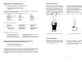
In a rectangular room the distance from the flame detector to the fire is calculated by the
formula:
Maximum distance = √
24Vdc Normal
+
R
-
+
-
L² + W² + H²
(Break supply to reset
if detector set to latch)
Zone
In the example shown in fig 1 the room in which the flame detector is to be installed measures
20m x 10m x 5m; the maximum distance from the detector to the flame will therefore be;
Refer to note 2
FIRE
IR
SENS
OR
Flame Detector
Fault
Relay
NOTE 3
EOL = End of line device required by some control
units. This is required to monitor the cable to the
detectors and prevent fault indications on the control
unit.
Refer to note 3
Fig 9
Maximum distance = √
Height
NOTE 2
R = To indicate fire to control unit or interface.
E.g.: - 470R
EOL
Fire
Relay
+ 1
- 25
6
7
8
20² + 10² + 5² = 22.9m
Width
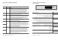
4 Wire Connection Diagram
Length
The circuit shown above enables the flame detectors to interface with most type of fire alarm control
systems. The fire relay RL1 is used to switch the required alarm load ‘R’ to generate a fire alarm
signal. An end of line device ‘EOL’ mounted in the last detector provides the system with the ability
to monitor the detector fault relay RL2 and the integrity of the interconnecting cables.
Fig 1 Calculation of distance from detector to flame
Field of View
The flame detector has a field of view of approximately 90°, as shown in the diagram below.
Installation
It is important that the detectors are installed
in such a way that all terminals and
connections are protected to at least IP20
with the detector cover fitted. The earth
bonding terminals are provided for
convenience where continuity of a cable
sheath or similar if required.
Adjustable mounting brackets and weather
shields are available as shown below.
FIRE
IR SENS
OR
90° Cone
Fig 2 Conical field of view of the flame detector
Fig 10 Stainless Steel Adjustable Mount
Fig 11 Stainless Steel Weather Shield
10
3