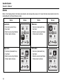
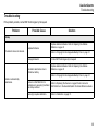
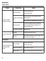
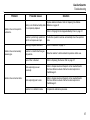
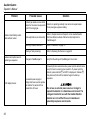
1
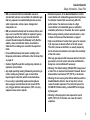
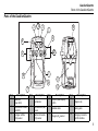
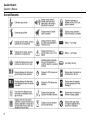
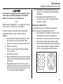
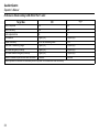
1, 2, 3, and 4 Gas Detector
50104941-536
English
©2013 BW Technologies by Honeywell. All rights reserved.
Operator’s Manual
GasAlertQuattro
Table of Contents
Limited Warranty and Limitation Liability .............. 0
Contacting BW Technologies by Honeywell ......... 0
Introduction .............................................................. 1
Zeroing the Sensors ................................................ 1
Safety Information - Read First ............................... 2
Parts of the GasAlertQuattro .................................. 5
Screen Elements ...................................................... 6
Pushbutton ............................................................... 7
Sensor Poisons and Contaminants ........................ 8
Connecting the Gas Cylinder to the Detector ....... 9
Calibration .............................................................. 10
Bump Test ............................................................... 12
Alarms ..................................................................... 14
User Options and Sensor Configuration ............. 17
Device Configuration ...................................................17
Sensor Configuration ...................................................19
Maintenance ........................................................... 20
WEEE Directive and Battery Directive ................. 24
Removal and Disposal of the Alkaline Battery
Pack ........................................................................24
Removal and Disposal of the Rechargeable
Battery Pack ............................................................24
Removal and Disposal of the Coin Cell ............... 25
Replacing the Sensors.................................................26
Replacing the Sensor Filter .........................................27
Specifications ......................................................... 28
European Performance Approval ......................... 31
Performance Data According to EN 45544-1
Part 1 and 2: ............................................................34
Troubleshooting ..................................................... 35
Startup Troubleshooting ..............................................40
Calibration Troubleshooting .........................................42
Bump Test Troubleshooting.........................................42
Replacement Parts and Accessories ................... 43
Rechargeable Battery Capacity ...................................20
Battery Pack Retaining Screw .....................................20
Replacing the Battery Pack .........................................21
Charging the Rechargeable Battery Pack ...................21
Replacing the Alkaline Batteries ..................................22
i
Limited Warranty and Limitation Liability
BW Technologies LP (BW) warrants the product to be free from defects in material and workmanship under normal use and service for a period of
two years, beginning on the date of shipment to the buyer. This warranty extends only to the sale of new and unused products to the original buyer.
BW’s warranty obligation is limited, at BW’s option, to refund of the purchase price, repair or replacement of a defective product that is returned to
a BW authorized service center within the warranty period. In no event shall BW’s liability hereunder exceed the purchase price actually paid by the
buyer for the Product.
This warranty does not include:
a) fuses, disposable batteries or the routine replacement of parts due to the normal wear and tear of the product arising from use;
b) any product which in BW’s opinion, has been misused, altered, neglected or damaged, by accident or abnormal conditions of operation,
handling or use;
c) any damage or defects attributable to repair of the product by any person other than an authorized dealer, or the installation of unapproved
parts on the product; or
The obligations set forth in this warranty are conditional on:
a) proper storage, installation, calibration, use, maintenance and compliance with the product manual instructions and any other applicable
recommendations of BW;
b) the buyer promptly notifying BW of any defect and, if required, promptly making the product available for correction. No goods shall be
returned to BW until receipt by the buyer of shipping instructions from BW; and
c) the right of BW to require that the buyer provide proof of purchase such as the original invoice, bill of sale or packing slip to establish that the
product is within the warranty period.
THE BUYER AGREES THAT THIS WARRANTY IS THE BUYER ’S SOLE AND EXCLUSIVE REMEDY AND IS IN LIEU OF ALL OTHER WARRANTIES, EXPRESS OR IMPLIED,
INCLUDING BUT NOT LIMITED TO ANY IMPLIED WARRANTY OF MERCHANTABILITY OR FITNESS FOR A PARTICULAR PURPOSE. BW SHALL NOT BE LIABLE FOR ANY
SPECIAL, INDIRECT, INCIDENTAL OR CONSEQUENTIAL DAMAGES OR LOSSES, INCLUDING LOSS OF DATA, WHETHER ARISING FROM BREACH OF WARRANTY OR
BASED ON CONTRACT, TORT OR RELIANCE OR ANY OTHER THEORY.
Since some countries or states do not allow limitation of the term of an implied warranty, or exclusion or limitation of incidental or consequential
damages, the limitations and exclusions of this warranty may not apply to every buyer. If any provision of this warranty is held invalid or
unenforceable by a court of competent jurisdiction, such holding will not affect the validity or enforceability of any other provision.
Contacting BW Technologies by Honeywell
USA: 1-888-749-8878
Europe: +44(0) 1295 700300
Canada: 1-800-663-4164
Other countries: +1-403-248-9226
Email us at: [email protected]
Visit BW Technologies by Honeywell’s website at: www.gasmonitors.com
GasAlertQuattro
iii
GasAlertQuattro
Introduction
GasAlertQuattro
Introduction
The operator’s manual provides basic information to operate
the GasAlertQuattro gas detector. For complete operating
instructions, refer to the GasAlertQuattro Technical Reference
Guide provided on the CD-ROM. The GasAlertQuattro gas
detector (“the detector”) is designed to warn of hazardous gas
levels above user-defined alarm setpoints.
The detector is a personal safety device. It is your responsibility
to respond properly to the alarm.
Note
The detector is shipped with English as the default
displayed language. Additional languages provided
are French, German, Portuguese, and Spanish. The
screens for the additional languages are displayed on
the detector and in the corresponding operator’s
manual.
Zeroing the Sensors
To zero the sensors, refer to steps #1-3 in Calibration on
page 10.
1
GasAlertQuattro
Operator’s Manual
Safety Information - Read First
Use the detector only as specified in this operator’s manual and
the technical reference guide, otherwise protection provided by
the detector may be impaired. Read the following Cautions
before using the detector.
• Warning: Substitution of components may impair
Intrinsic Safety.
• Before using the detector, refer to Sensor Poisons and
Contaminants on page 8.
• Protect the combustible sensor from exposure to lead
compounds, silicones, and chlorinated hydrocarbons.
Although certain organic vapors (such as leaded
gasoline and halogenated hydrocarbons) may
temporarily inhibit sensor performance, in most cases
the sensor will recover after calibration.
• Caution: For safety reasons, this equipment must be
operated and serviced by qualified personnel only. Read
and understand the technical reference guide
completely before operating or servicing.
• If using the detector near its upper or lower operating
temperature, BW Technologies by Honeywell
recommends zeroing or activating the detector in that
environment.
• Charge the detector before first-time use. BW
recommends the detector be charged after every
workday.
2
• Do not use an external power supply or charger to
operate the detector for periods greater than 24 hours. If
powering from an external source, power cycle the
detector once every 24 hours to ensure proper
operation. To power cycle the detector, press and hold
C until OFF is displayed. Release C, then press and
hold until the detector begins the start-up sequence.
• Do not use an external power source or charger to
operate the detector in a hazardous environment. The
chargers intended for use with the GasAlertQuattro
detector are not certified for use in hazardous or
potentially explosive environments.
• Calibrate the detector before first-time use and then on
a regular schedule, depending on use and sensor
exposure to poisons and contaminants. BW
recommends that the sensors must be calibrated
regularly and at least once every 180 days (6 months).
• Performance standards for European certification
EN 60079-29-2 and EN 45544-4 contain guidance on
implementing a suitable calibration routine.
• Calibrate only in a safe area that is free of hazardous
gas in an atmosphere of 20.9% oxygen.
• The combustible sensor is factory calibrated to 50%
LEL methane. If monitoring a different combustible gas
in the % LEL range, calibrate the sensor using the
appropriate gas.
• Only the combustible gas detection portion of this
instrument has been assessed for performance by CSA
International.
GasAlertQuattro
Safety Information - Read First
• BW recommends that the combustible sensor be
checked with a known concentration of calibration gas
after any exposure to contaminants/poisons such as
sulfur compounds, silicon vapors, halogenated
compounds, etc.
• BW recommends to bump test the sensors before each
day’s use to confirm their ability to respond to gas by
exposing the detector to a gas concentration that
exceeds the alarm setpoints. Manually verify that the
audible, visual, and vibrator alarms are activated.
Calibrate if the readings are not within the specified
limits.
• For an additional bump test caution relating to the
European performance certification, refer to Bump Test
on page 12.
• Caution: High off-scale LEL readings may indicate an
explosive concentration.
• Any rapid upscaling reading followed by a declining or
erratic reading may indicate a gas concentration
beyond upper scale limit, which can be hazardous.
• For use only in potentially explosive atmospheres
where oxygen concentrations do not exceed 20.9%
(v/v). Oxygen deficient atmospheres (<10% v/v) may
suppress some sensor outputs.
• Extended exposure of the GasAlertQuattro to certain
concentrations of combustible gases and air may stress
the detector element that can seriously affect its
performance. If an alarm occurs due to a high
concentration of combustible gases, a calibration
should be performed, or if needed, the sensor replaced.
• Before using common products around sensors, refer
to Sensor Poisons and Contaminants on page 8.
• High concentrations of certain toxic gases, for example
H2S, may have an adverse effect on the LEL sensor.
This effect, known as inhibition, is usually temporary
but in extreme circumstances can impair the sensitivity
of the LEL sensor.
After any gas exposure that causes an alarm in the toxic
gas sensors, the LEL sensor should be verified with a
bump test, and recalibrated if necessary.
• Warning: The lithium battery (QT-BAT-R01) may present
a risk of fire or chemical burn hazard if misused. Do not
disassemble, heat above 212°F (100°C), or incinerate.
• Warning: Do not use any other lithium batteries with the
GasAlertQuattro detector. Use of any other cell can
cause fire and/or explosion. To order and replace the
QT-BAT-R01 lithium battery, contact BW Technologies
by Honeywell.
• Warning: Lithium polymer cells exposed to heat at
266°F (130°C) for 10 minutes can cause fire and/or
explosion.
3
GasAlertQuattro
Operator’s Manual
•
e
Warning: This instrument contains a lithium
polymer battery. Dispose of used lithium cells
immediately. Do not disassemble and do not dispose of
in fire. Do not mix with the solid waste stream. Spent
batteries must be disposed of by a qualified recycler or
hazardous materials handler.
• Keep lithium cells away from children.
• Deactivating the detector by removing the battery pack
may cause improper operation and harm the detector.
4
GasAlertQuattro
Parts of the GasAlertQuattro
Parts of the GasAlertQuattro
2
1
2
4
9
2
2
5
8
6
Item
Description
Item
1
IntelliFlash
(green LED)
Visual alarm indicator
(red LED)
Hydrogen sulfide
(H2S) sensor
4
3
11
12
7
2
10
3
Description
Pushbutton
Item
7
5
Combustible (LEL)
sensor
8
6
Carbon monoxide
(CO) sensor
9
Description
Liquid crystal display
(LCD)
Audible alarm
Oxygen (O2) sensor
Item
10
11
12
Description
Alligator clip
Battery pack
Charging connector
and IR interface
5
GasAlertQuattro
Operator’s Manual
Screen Elements
6
GasAlertQuattro
Pushbutton
Pushbutton
Pushbutton
Description
• To activate the detector, press and hold C in a safe area that is free of hazardous gas and in
an atmosphere of 20.9% oxygen.
• To deactivate the detector, press and hold C during the powering off countdown. Release
C when OFF displays.
• To view the date/time, current battery power, calibration due date, bump test due date, TWA,
STEL, and peak readings, press C twice rapidly. To clear the TWA, STEL, and peak
readings, press and hold C when the LCD displays Hold C to reset peaks, TWA, STEL.
C
• To initiate calibration, press and hold C while the detector performs the OFF countdown.
Continue holding C while the LCD briefly deactivates and then reactivates to begin the
calibration countdown. Release C when Calibration started displays.
• To activate the backlight, press C and release.
• To acknowledge latching alarms, press C.
• To acknowledge a low alarm and disable the audible alarm, press C. The Low Alarm
Acknowledge option must be enabled in FleetManager II.
• To acknowledge any of the “due today” messages (calibration and bump test) press C. If
enabled, the force calibration and force bump features cannot be bypassed.
7
GasAlertQuattro
Operator’s Manual
Sensor Poisons and Contaminants
Several cleaners, solvents, and lubricants can contaminate and
cause permanent damage to sensors. Before using cleaners,
solvents, and lubricants in close proximity to the detector
sensors, read the following caution and table.
Use only the following BW Technologies by Honeywell
recommended products and procedures:
•
•
•
•
Use water based cleaners.
Use non-alcohol based cleaners.
Clean the exterior with a soft, damp cloth.
Do not use soaps, polishes, or solvents.
The following table lists common products to avoid using
around sensors.
Cleaners and
Lubricants
Silicones
Aerosols
Brake cleaners
Silicone cleaners and
protectants
Bug
repellents
and sprays
Lubricants
Silicone based
adhesives, sealants,
and gels
Lubricants
Rust inhibitors
Hand/body and
medicinal creams that
contain silicone
Rust
inhibitors
Window and glass
cleaners
Tissues containing
silicone
Window
cleaners
Dishsoaps
Mold releasing agents
Citrus based
cleaners
Polishes
Alcohol based
cleaners
Hand sanitizer
Anionic
detergents
Methanol (fuels
and antifreezes)
8
GasAlertQuattro
Connecting the Gas Cylinder to the Detector
Connecting the Gas Cylinder to the Detector
Gas Cylinder Guidelines
Ɣ To ensure accurate calibration, use a premium-grade calibration gas. Use
gases approved by the National Institute of Standards and Technology.
Ɣ,IDFHUWLILHGFDOLEUDWLRQLVUHTXLUHGFRQWDFW%:7HFKQRORJLHVE\+RQH\ZHOO
Ɣ'RQRWXVe a gas cylinder past its expiration date.
Gas Cylinder Connection
Read the following steps (1-5) prior to initiating calibration.
Note
Only use the calibration cap
during the calibration process.
1. Verify the calibration gas being used matches the span concentration
value(s) that are set for the detector.
2. Connect the calibration hose to the 0.5 l/min regulator on the gas cylinder.
For use with the MicroDock II, use a demand flow regulator and refer to
the MicroDock II User Manual.
3. Connect the calibration hose to the intake inlet on the calibration cap.
Arrows on the calibration cap indicate the direction of gas flow.
4. Begin the calibration procedures. Do not attach the calibration cap until
instructed to apply gas. When instructed, place the calibration cap on the
detector and tighten the knob.
NOTE: Ensure the cap is securely fastened before applying gas.
5. When calibration is complete, disconnect the hose from the calibration cap
and the regulator. Remove the calibration cap from the detector.
9
GasAlertQuattro
Operator’s Manual
Calibration
Calibration is performed to adjust the sensitivity levels of
sensors to ensure accurate responses to gas.
1. Press and hold C as the detector
performs the Powering off countdown.
OFF
This calibration procedure is written as the procedure is intended.
If an error or alarm screen displays, refer to Calibration
Troubleshooting in the GasAlertQuattro Technical Reference
Guide.
Powering off...
Calibrate only in a safe area that is free of hazardous gas
in an atmosphere of 20.9% oxygen.
If performing single gas calibration, calibrate O2 first.
Continue holding C when OFF
displays and the detector briefly
deactivates.
OFF
Note
The maximum hose length for calibration is 3 ft. (1 m).
The following steps are written for use with a standard
quad gas cylinder.
Calibration can only be aborted after the sensors have
been zeroed. If C is pressed to abort, CALIBRATION
cancelled displays.
Aborting the calibration procedure after applying gas may
result in an undesired calibration being saved.
BW recommends calibrations be verified following an
adjustment operation.
10
2. The detector activates again and
performs the calibration countdown.
Continue holding until Starting
Calibration displays.
Starting Calibration...
Continue holding
to calibrate
or zero
- 3 -
GasAlertQuattro
Calibration
3. The detector enters the zero function.
zeroing displays while the detector
zeros all of the sensors.
If a sensor fails to zero, it cannot be
calibrated. Refer to Startup Self-Test
Troubleshooting in the
GasAlertQuattro Technical Reference
Guide.
If the IR Lock option is enabled, the
following screen displays to indicate
calibration can only be performed using
an IR device (MicroDock II or IR Link).
H2S ppm
0.0
20.9
O2 %
CO ppm
0
0
detected,
displays beside each gas
that is detected.
LEL %
Apply Calibration
gas now...
H2S
CO
O2
LEL
Press
zeroing . . .
Calibration
IR lock enabled...
Connect to
MicroDock or
Fleet Manager
Press
to end
waiting... 24
4. When the following screen displays,
attach the calibration cap and apply
calibration gas at a flow rate of
250-500 ml/min. Refer to Connecting the
Gas Cylinder to the Detector on page 9.
If a sensor is not yet due for calibration,
its box will have a greyed out
checkmark.
5. The detector initially tests for gas.
When a sufficient amount of gas is
Apply Calibration
gas now...
H2S
CO
O2
LEL
Press
to end
waiting... 17
to end
waiting... 0
6. The detector then begins calibrating
the sensors. The following activities
occur during the span:
• calibrating displays at the bottom of
the screen.
• Gas values adjust during the span.
• Target gas values that are defined in
FleetManager II display above or
below the adjusting gas value.
To abort calibration after the sensors
have been zeroed, press C.
7. When the following screen displays,
close the valve on the gas cylinder and
remove the calibration cap from the
detector.
A check mark displays beside each
sensor that has calibrated successfully.
H2S ppm
CO ppm
22.0
86
25.0
100.0
18.0
50.0
15.0
37
O2 %
Press
LEL %
to end
calibrating...
Turn gas off...
H2S
CO
O2
LEL
Press
to skip
waiting... 17
11
GasAlertQuattro
Operator’s Manual
Bump Test
8. When calibration is complete, the
following screen displays.
Note
The calibration due date cannot
be reset for a sensor that fails
calibration. If a sensor fails or an
error screen displays, refer to
Calibration Troubleshooting in the
GasAlertQuattro Technical
Reference Guide.
9. All successfully calibrated sensors
automatically reset to the number of days
defined in the Cal Interval field in
FleetManager II.
The calibration due dates can be
changed in FleetManager II.
Press
H2S days
CO days
NEXT
CAL
180
180
Press
H2S ppm
0.0
20.9
O2 %
12
to skip
waiting... 0
O2 days
10. The detector now enters normal
operation.
A bump test applies test gas to force the detector into alarm. A
bump test should be performed regularly to confirm the sensors
are responding correctly to gas, and that the audible, visual and
vibrator alarms activate during an alarm condition.
Calibration
complete
180
180
LEL days
to skip
CO ppm
0
0
LEL %
The detector can also prompt for a bump test during startup
when the Bump Test Interval is defined. Refer to the
GasAlertQuattro Technical Reference Guide.
BW recommends to bump test the sensors before each
day’s use to confirm their ability to respond to gas by
exposing the sensors to a gas concentration that exceeds
alarm setpoints.
To operate the detector in accordance with performance
requirements for European certification, the user must
complete a bump test before each day’s use.
(Per EN 60079-29-1 and EN 60079-29-2.)
1. Connect the calibration hose to the 0.5 l/min regulator
on the gas cylinder. Refer to Connecting the Gas
Cylinder to the Detector on page 9.
To bump test using the MicroDock II station, refer to the
MicroDock II User Manual.
2. Connect the calibration hose to the intake inlet on the
calibration cap. Arrows on the calibration cap indicate
the direction of gas flow.
GasAlertQuattro
Bump Test
3.
4.
Attach and tighten the calibration cap onto the
detector and apply gas. Verify the visual, audible, and
vibrator alarms activate.
Close the regulator and remove the calibration cap.
The detector temporarily remains in alarm until the
gas clears from the sensors.
Note
In normal operating mode, it is possible to display
measured values with calibration gas applied to
determine any measurement errors.
13
GasAlertQuattro
Operator’s Manual
Alarms
Refer to the following table for information about alarms and corresponding screens. For more information about alarms refer to the
GasAlertQuattro Technical Reference Guide.
Alarm
Low Alarm
• Slow siren (upward tone)
• Slow flash
• Black box around gas flashes
• Vibrator alarm activates
Screen
H2S ppm
0.0
LOW
High Alarm
• Fast siren (downward tone)
• Fast flash
• Black box around gas flashes
• Vibrator alarm activates
14
%
H2S ppm
0.0
HIGH
20.9
O2
CO ppm
0
ALARM
19.5
O2
Alarm
%
0
LEL
200
ALARM
0
%
Screen
H2S ppm
15.0
TWA
STEL Alarm
• Fast siren (downward tone)
• Fast flash
• Black box around gas flashes
• Vibrator alarm activates
%
H2S ppm
0.0
STEL
0
0
LEL
%
CO ppm
50
ALARM
20.9
O2
CO ppm
ALARM
20.9
O2
%
CO ppm
LEL
TWA Alarm
• Fast siren (downward tone)
• Fast flash
• Black box around gas flashes
• Vibrator alarm activates
%
0
LEL
%
GasAlertQuattro
Alarms
Alarm
Multi Alarm
• Alternating low and high alarm
siren and flash
• Black box around gas flashes
• Type of alarm alternates
• Vibrator alarm activates
Screen
H2S ppm
0.0
HIGH
19.5
O2
%
Alarm
CO ppm
200
ALARM
0
LEL
%
Sensor Failure Alarm
•
displays
H2S ppm
0.0
20.9
O2 %
CO ppm
0
Over Limit (OL) Alarm
• Fast siren (downward tone)
• Fast flash
• Black box around gas flashes
• Vibrator alarm activates
Note: LCD may also display
an under limit reading (-OL)
Normal Deactivation
• Sequence of alternating beeps
and alternating flashes
• Vibrator alarm activates
• Countdown initiates
• OFF displays
Screen
H2S ppm
0.0
CO ppm
0
HIGH
ALARM
20.9
O2
OL
%
LEL
%
OFF
LEL %
Note
If enabled, during an alarm condition the Latching Alarms option causes the low and high gas alarms (audible, visual, and vibrator) to
persist until the alarm is acknowledged by pressing C and the gas concentration is below the low alarm setpoint. The peak concentration
values display continually until the alarm no longer exists. Enable/disable Latching Alarms in FleetManager II. Local regulations may
require the Latching Alarms option be enabled. The Latching Alarms option must be enabled if the detector is to be used in accordance
with performance requirements for European certification.
15
GasAlertQuattro
Operator’s Manual
Alarm
Low Battery Alarm
• Sequence of 10 rapid sirens and
alternating flashes with 7 seconds
of silence in between (continues
for 15 minutes)
•
flashes
• Vibrator alarm pulses
• After 15 minutes of the low battery
alarm sequence, the detector
enters critical battery alarm (see
Critical Battery Alarm below)
Critical Battery Alarm
• Fifteen minutes after low battery
alarm activates, sequence of
10 rapid sirens and alternating
flashes with 1 second of silence in
between (sequence reactivates
seven times)
• Vibrator alarm pulses
• Low Battery Powering Off
displays and the detector
deactivates
16
Screen
H2S ppm
0.0
20.9
O2 %
CO ppm
0
0
LEL %
Alarm
Screen
Confidence/compliance Beep
• One beep every 1-120 seconds
(beep frequency is defined with
Confidence/compliance Beep
Interval option)
IntelliFlash
H2S ppm
0.0
20.9
O2 %
CO ppm
0
0
LEL %
(default: one flash every 1 second)
• One flash every 1-120 seconds
(flash frequency is defined with
IntelliFlash Interval option)
Heartbeat
Note: Confidence/
compliance beep and
IntelliFlash
automatically deactivate
during a low battery
•
pulses once every second to alarm, calibration fail,
verify detector is operating correctly bump test fail, self-test
fail, and in an alarm
condition.
Note
Low battery
Powering off
If the Low Alarm Acknowledge option is enabled, the
audible alarm can be disabled during a low alarm condition.
The LED and visual alarm indicators remain active until the
alarm condition changes or the detector deactivates. Press
C to acknowledge the low alarm and deactivate the audible
alarm. If the alarm escalates to a high, TWA, or STEL alarm,
the audible alarm reactivates.
GasAlertQuattro
User Options and Sensor Configuration
User Options and Sensor Configuration
In order to modify user options and detector configuration, the
following items are required:
• Detector
• IR Link adapter or MicroDock II
• FleetManager II software
The following section describes some of the configuration
options available in the detector. Refer to the GasAlertQuattro
Technical Reference Guide and FleetManager II Operator’s
Manual for complete information.
Device Configuration
The Device Configuration section displays data about the
detector, allows for a startup message to be entered, and
defines and enables/disables settings for the detector.
• Serial Number Field: This field displays the serial number
(e.g. QA111-001000) of the detector.
• Firmware Version: This field displays the current firmware
version that displays on the detector LCD during the
startup sequence. If new firmware is uploaded to the
detector, the Firmware Version field automatically updates.
• Hardware Version: This field displays the current
hardware version of the detector.
• Startup Message: Enter text to display on the detector
LCD during startup (50 characters maximum). Enter
information such as employee name, plant, area,
emergency number(s), etc.
• Lockout on Self-Test Error: If Lockout on Self-Test Error
is enabled and a failure occurs during the self-test, the
screen displays Sensor Self Test Error Lockout
Enabled... and the detector deactivates.
• Safe Mode: If enabled, SAFE displays continuously on the
LCD unless an alarm condition occurs.
• Confidence/Compliance Beep: If enabled, the
Confidence/Compliance Beep provides continuous audible
confirmation that the detector is operating correctly.
Frequency of the beep is defined with the Confidence/
Compliance Beep Interval option (every 1-120 seconds).
Note
Confidence/Compliance Beep automatically disables
during a low battery alarm, self-test fail, calibration
fail, bump test fail, and when an alarm event occurs.
Remove the unit from use and contact BW if the
confidence/compliance beep or IntelliFlash is not
working.
• Latching Alarms: If enabled, during an alarm condition
the Latching Alarms option causes the low and high gas
alarms (audible, visual, and vibrator) to persist until the
alarm is acknowledged and the gas concentration is below
the low alarm setpoint. The LCD displays the peak
concentration until the alarm no longer exists. Local
regulations in your region may require the Latching
Alarms option be enabled.
17
GasAlertQuattro
Operator’s Manual
• Force Calibration: If enabled, during startup if a sensor(s)
is past due for calibration, the sensor(s) must be calibrated
to continue and enter normal operation.
A value must be entered in the Cal Interval (days) field
before enabling Force Calibration.
• Force Bump: If enabled, during startup if the sensor(s) is
past due for a bump test, a bump test should be performed
and the overdue sensor(s) must enter into alarm.
A value must be entered in the Bump Interval (days) field
before enabling Force Bump.
• Cal IR Lock: If enabled, the sensor(s) can only be
calibrated using an IR device (IR Link or the MicroDock II
station).
• Stealth: When enabled, the following features are
disabled: backlight, audible alarms, visual alarms,
IntelliFlash, and confidence/compliance beep. Only the
vibrator and the LCD readings activate during an alarm
condition.
Note
•
Note
If the Cal IR Lock option is enabled and a manual
calibration is attempted, the sensor(s) will auto zero
but they will not be calibrated.
•
Do not use for gas detection while connected to a PC.
• Flip Display: The detector can display screens at 0°
(upright) or 180° (upside down), depending upon how the
detector is worn by the worker. If the Flip Display option is
enabled, the LCD is viewed at 180° (upside down).
18
•
•
Should the user wish to comply with European
performance certifications, stealth mode must be
disabled.
Datalog Interval: The Datalog Interval (seconds) field
defines how often the detector records a datalog (every
1-120 seconds). Enter the desired value.
The total number of 8-hour days datalogs that can be
recorded is assuming 90% of the day has no gas
concentrations.
When the memory is full, the detector replaces the oldest
datalogs with the most recent datalogs.
IntelliFlash Interval: The IntelliFlash Interval (seconds)
field defines how often (every 1-120 seconds) the
IntelliFlash occurs.
Confidence/Compliance Beep Interval: Define how
often (every 1-120 seconds) the confidence/compliance
beep occurs.
Language: The Language field provides a drop down
menu that includes the following language options:
English, Français (French), Deutsch (German), Español
(Spanish), Português (Portuguese). Select the language
from the drop-down menu in FleetManager II.
GasAlertQuattro
User Options and Sensor Configuration
Sensor Configuration
• Sensor Disabled: Enables/disables the selected sensor.
Use extreme caution when disabling a sensor. The
disabled sensor cannot detect and alarm against the
applicable gas.
• Calibration Gas (ppm): Define the span gas
concentration for each sensor. The span gas concentration
must match the span value on the gas cylinder.
• Calibration Interval: Define how often a sensor should be
calibrated (0-365 days) in the Calibration Interval (days)
field. A different calibration interval can be defined for each
sensor.
BW recommends that the sensors be calibrated at least
once every 180 days (6 months).
• Bump Interval: Define how often a bump test should be
performed for each sensor (0-365 days) in the Bump
Interval (days) field. A different bump interval can be
defined for each sensor.
• Low Alarm: Define the low alarm setpoints for each
sensor. Refer to Sample Gas Alarm Setpoints for factory
defined alarm setpoints in the GasAlertQuattro Technical
Reference Guide.
• High Alarm: Define the high alarm setpoints for each
sensor. Refer to Sample Gas Alarm Setpoints for factory
defined alarm setpoints in the GasAlertQuattro Technical
Reference Guide.
• TWA Alarm: The time-weighted average (TWA) is a safety
measure used to calculate accumulated averages of
gases. Using the US Occupational Safety and Health
Administration (OSHA) method or the American
Conference of Governmental Hygienists (ACGIH) method,
an average is calculated to ensure the detector alarms
when the TWA has accumulated.
• STEL Alarm: The short-term exposure limit (STEL) is the
maximum permissible gas concentration a worker can be
safely exposed to for short periods of time (5-15 minutes
maximum).
• Correction Factor (LEL): The Correction Factor option
defines compensation factors for hydrocarbons other than
methane. The correction factor is only applicable to LEL
and can only be applied if the LEL sensor has been
calibrated with methane. Detector operation using LEL
correction factors has not been tested by BAM.
• STEL Interval: Define the short-term exposure limit
(STEL) from 5-15 minutes (toxic sensors only).
• TWA Period (hours): Define the time-weighted average
(TWA) from 4-16 hours (toxic sensors only).
• TWA Method: Select either the US Occupational Safety
and Health Administration (OSHA) or the American
Conference of Governmental Industrial Hygienists
(ACGIH) TWA calculating method.
19
GasAlertQuattro
Operator’s Manual
• 50% LEL = (%CH4): Enter a percentage value to display
the LEL reading as %vol., assuming a methane
environment (LEL only).
• Auto Zero on Startup: When enabled, the sensors
automatically zero during the startup sequence. The Auto
Zero on Startup option is available for the CO, H2S, LEL,
and O2 sensors (each sensor is enabled individually).
• LEL by Volume CH4: If enabled, the detector displays the
LEL value as %vol. assuming a methane environment.
Note
If changing the measurement unit from % LEL to
% Vol. or from % Vol. to % LEL, a calibration must be
completed and the alarm setpoints changed. For
calibration information refer to Calibration on page 10
and for alarm setpoint information refer to Gas Alarm
Setpoints in the GasAlertQuattro Technical
Reference Guide.
• 10% LEL (of reading) Over-span: If enabled, the detector
automatically over-spans the LEL sensor by 10% of the
span concentration. Enable 10% LEL (of reading)
Over-Span to ensure the detector is in compliance with
CAN/CSA C22.2 No. 152.
• 20.8 Base Reading: If enabled, the detector is configured
to detect 20.8% O2 as ambient air. When disabled, the
detector is configured to detect 20.9% O2 as ambient air.
20
• Low Alarm Acknowledge: If enabled, the audible alarm
can be temporarily disabled during a low alarm by
pressing C. The vibrator, alarm LEDs, and LCD remain
operational (toxic and LEL only).
Maintenance
To maintain the detector in good operating condition, perform
the following basic maintenance as required.
• Calibrate, bump test, and inspect the detector on a regular
schedule.
• Maintain an operations log of all maintenance, bump tests,
calibrations, and alarm events.
• Clean the exterior with a soft damp cloth. Do not use
solvents, soaps, or polishes. Refer to Sensor Poisons and
Contaminants on page 8.
Rechargeable Battery Capacity
A rechargeable battery’s runtime decreases approximately 20%
over a two-year period of typical use.
Battery Pack Retaining Screw
The retaining screw (QAQD-20x) provided with the detector
must be used to lock the battery pack on all European and
IECEx scheme detectors, and on all Canadian and U.S. Zone
Certified detectors.
The screwdriver included with the detector has a double-ended
driver. Loosen the brass nut to switch between a Phillips head
and a hex head.
GasAlertQuattro
Maintenance
A hex tool is required to tighten and loosen the retaining screw.
Tighten the screw 1-2 turns using 3-4 in-lbs of torque. Do not
overtighten the screw.
4.
5.
Hex tool
Retaining
screw
Battery
release latch
Battery
pack
Replacing the Battery Pack
The alkaline and rechargeable battery packs can be changed in
hazardous locations.
1. Press and hold C to deactivate the detector.
2. If using the retaining screw, loosen it 1-2 turns. Push
the battery release latch toward the top of the
detector to release the battery pack.
3. From the top of the battery pack, lift upward to
remove.
Before replacing the battery pack, ensure the seal on
the instrument and battery pack is free of debris and
moisture.
Insert a new battery pack. Insert the bottom of the
battery pack first, then lower the top into place. Press
until the release tab engages. Tighten the retaining
screw if required.
Charging the Rechargeable Battery Pack
To avoid personal injury and/or damage to the detector,
adhere to following:
• Charge only in a safe area that is free of hazardous gas
within temperatures of 32°F to 104°F (0°C to 40°C).
• Charge the battery immediately when the detector emits
a low battery alarm.
• Charge the lithium battery pack using the BW supplied
charger and charger adapter only. The charging adapter
is specific to your region. Use of the charging adapter
outside your region will damage the charger and the
detector. Failure to adhere to this caution can lead to
fire and/or explosion.
• Charge the lithium battery after each workday.
• Ensure the charging connector surface is free of debris
and moisture.
• Do not use an external power supply or charger to
operate the detector for periods greater than 24 hours. If
powering from an external source, power cycle the
detector once every 24 hours to ensure proper
operation. To power cycle the detector, press and hold
21
GasAlertQuattro
Operator’s Manual
C until OFF is displayed. Release C, then press and
hold until the detector begins the start-up sequence.
• Do not use an external power source or charger to
operate the detector in a hazardous environment. The
chargers intended for use with the GasAlertQuattro
detector are not certified for use in hazardous or
potentially explosive environments.
1. Press and hold C to deactivate the detector, then
plug the charger into an AC outlet.
Note
The time required to charge will increase if the detector is
activated.
2.
Connect the charging adapter to the detector IR
receptacle. Refer to the following illustration.
IR receptacle
Charging adaptor
3.
22
The lithium battery may require 6 hours to reach full
capacity.
Replacing the Alkaline Batteries
To avoid personal injury and/or damage to the detector,
use only BW recommended alkaline batteries. Refer to
Specifications on page 28.
Change the alkaline batteries only in safe area that is free
of hazardous gas.
1. Press and hold C to deactivate the detector.
2. If using the retaining screw, loosen the retaining
screw 1-2 turns. Remove the alkaline battery pack.
Refer to Replacing the Battery Pack on page 21.
3. Unhook the ejector bar from the release clasp. Move
the ejector bar towards the top of the battery pack
until it is aligned horizontally over the batteries.
GasAlertQuattro
Maintenance
4.
Using the tab, pull on the ejector bar.
5.
To the left of the tab, pull up on the ejector bar.
6.
Remove the spent batteries. Reset the ejector bar to
its original flat position. Ensure the ejector bar
engages the release clasp.
7.
Insert the new batteries. Position the positive end of
the battery at a 30° angle and insert into the battery
pack before pushing the negative end down. Ensure
the batteries are not inserted over the tab.
23
GasAlertQuattro
Operator’s Manual
Note
Ensure all three batteries are
inserted with the positive end
pointing toward the top of the
battery pack.
WEEE Directive and Battery Directive
Failure to comply with the following battery removal and
disposal instructions may result in battery shorting, battery
leakage, and/or other damage. Ensure a qualified technician
completes the following procedures.
Removal and Disposal of the Alkaline Battery Pack
Only a qualified technician should complete the following
procedures.
8.
Before replacing the battery pack, ensure the seal on
the instrument and battery pack is free of debris and
moisture.
9. Replace the battery pack by inserting the bottom first,
then lower top into place. Ensure the tab is tucked in
before replacing the battery pack.
Press until the release tab engages. If required, tighten the
retaining screw using 3-4 in. lbs torque.
24
To remove the alkaline batteries, refer to steps #1 to #6 in
Replacing the Alkaline Batteries on page 22.
Removal and Disposal of the Rechargeable Battery Pack
To remove the rechargeable battery pack, refer to steps #1 to
#3 in Replacing the Battery Pack on page 21.
Dispose of the battery pack according local laws.
GasAlertQuattro
Removal and Disposal of the Coin Cell
Removal and Disposal of the Coin Cell
The detector contains a coin cell to power the real-time clock.
1.
2.
3.
4.
5.
6.
Press and hold C to deactivate the detector.
If the battery pack has not yet been removed, refer to
Removal and Disposal of the Alkaline Battery Pack
on page 24 or Removal and Disposal of the
Rechargeable Battery Pack on page 24.
Remove the six machine screws on the rear shell.
Remove the two screws on the main PCB.
Remove the main board.
The coin cell is connected to the board by four leads.
7.
Clip the four leads individually to remove the coin cell.
Only a qualified technician should complete the following
procedure.
1
2
3
4
Item
Description
1
Rear machine screws (6)
2
Rear shell
3
Front shell and PCB
4
Coin cell
Do not touch two or more leads when disconnecting the
battery cell.
8. Dispose of the coin cell according to local laws.
25
Replacing the Sensors
Rear shell
O2 sensor
H2S sensor
Sensor filter
with gasket
Front shell
Machine
screws (6)
LEL sensor
Battery pack
Side facing front shell
CO sensor
Side facing sensors
GasAlertQuattro
Removal and Disposal of the Coin Cell
8.
To avoid personal injury and/or property damage, only use
sensors that are specifically designed for the detector.
Replace the sensors in a non-hazardous area.
Note
Detectors that are configured for 1, 2, or 3 gases may contain a
dummy sensor in one of the four sensor locations.
To replace a sensor or sensor filter, refer to the illustration
Replacing the Sensors on page 26 and the following
steps #1-8.
1. Press and hold C to deactivate the detector. Press
the release latch, and remove the battery pack.
2. Remove the six machine screws from the rear shell.
3. Remove the front shell.
4. Remove the spent sensor(s). Ensure no damage
occurs to the LCD.
5. Insert the new sensor(s).
6. Before reassembling the detector, ensure the sealing
surfaces on the front and rear shells is free of debris
and moisture.
7. Reassemble the detector. Press the front and rear
shells together firmly to ensure a proper seal. Ensure
the front and rear shells have a tight, uniform 1/16 in.
(1.5 mm) seal on all sides of the detector.
9.
Replace the six machine screws using 3-4 in. lbs
torque. Do not overtighten the screws. Replace the
battery pack.
New sensors must be calibrated prior to use.
Calibrate the new sensor(s) immediately. Refer to
Calibration on page 10.
Replacing the Sensor Filter
To replace the filter, refer to the illustration Replacing the
Sensors on page 26 and the following steps #1-6.
1. Press and hold C to deactivate the detector. Press
the release latch, and remove the battery pack.
2. Remove the six machine screws from the rear shell.
3. Remove the front shell. Remove the sensor filter.
4. Refer to the following illustration before inserting the
new filter. Ensure the filter is laying flat and that the
holes are correctly aligned over the filter posts.
Facing front shell
Facing sensors
27
GasAlertQuattro
Operator’s Manual
5.
6.
7.
Before reassembling the detector, ensure the sealing
surfaces on the front and rear shells is free of debris
and moisture.
Replace the front shell. Press the front and rear
shells together firmly to ensure a proper seal. Ensure
the front and rear shells have a tight, uniform 1/16 in.
(1.6 mm) seal on all sides of the detector.
Replace the six machine screws using 3-4 in. lbs
torque. Do not overtighten the screws. Replace the
battery pack.
Specifications
Instrument dimensions: 13 x 8.1 x 4.7 cm
(5.1 x 3.2 x 1.5 in.)
Weight:
316 g (11.15 oz.) with rechargeable battery pack
338 g (11.92 oz.) with alkaline battery pack
Operating temperature: -20°C to +50°C (-4°F to +122°F)
Storage temperature: -40°C to +60°C (-40°F to +140°F)
Operating humidity: 10% to 100% relative humidity
(non-condensing)
Operating environment specifications for use according to
European performance approvals
(Oxygen and methane measurements)
Operating temperature range certified by BAM: -20°C to
+50°C
Operating humidity as tested by BAM: 5% r.H. to 95% r.H.
(Extended Range of Use for Temperature and Humidity as
Compared To EN 50104 (Oxygen performance) and
EN 67009-29-1 (LEL performance))
Storage temperature range tested by BAM: -25°C to +60°C
Operating pressure as tested by BAM: 80 kPA to 120 kPa
Storage duration: Two years from purchase date
Dust and moisture ingress: IP66/67 (with screw engaged)
Alarm setpoints: May vary by region and are user-defined
28
GasAlertQuattro
Specifications
Detection range:
H2S: 0 - 200 ppm (0.1 ppm increments from 0.0 to 39.9 ppm/
1 ppm increments above 40 ppm)
CO: 0 - 1000 ppm (1 ppm increments)
O2: 0 - 30.0% vol. (0.1% vol. increments)
Combustible (LEL): 0 - 100% (1% LEL increments) or
0 - 5.0% v/v methane
Sensor type:
H2S, CO, O2: Single plug-in electrochemical cell
Combustibles: Plug-in catalytic bead
O2 measuring principle: Capillary controlled concentration
sensor
Bump test specified limits: BW recommends using a gas
cylinder that will ensure the combustible sensor has an
accuracy of -0 to +20% of actual reading (reference CAN/CSA
C22.2 No. 152)
Alarm conditions: TWA alarm, STEL alarm, low alarm, high
alarm, multi alarm, over limit (OL) alarm, low battery alarm,
critical low battery alarm, sensor failure alarm, IntelliFlash,
confidence/compliance beep
Audible alarm: 95 dB at 30 cm (12 in.) variable pulsed beeper
Visual alarm: Red light-emitting diodes (LEDs)
IntelliFlash: Green light-emitting diode. Flash frequency is
user-defined with IntelliFlash interval option
Confidence/compliance beep: Audible beep from variable
pulsed beeper. Beep frequency is user-defined with confidence/
compliance beep interval option
Minimum performance compliance: IntelliFlash should be set
to no slower than 4 seconds to comply with European
Regulations
Display: Alphanumeric liquid crystal display (LCD) with flip
display (0° or 180°) capability (user-defined in FleetManager II)
Backlight: Activates upon startup and deactivates when
self-test is complete. Activates when the pushbutton is pressed
and deactivates after 10 seconds. Also activates during an
alarm condition and remains lit until alarm ceases
Internal vibrator: Vibrates during activation, deactivation, and
all alarms
Self-test: Initiated during activation, self-test runs continuously
on the battery and electrochemical sensors (H2S and CO) while
detector is operational
Calibration: Zero and automatic span
User options: Startup message, lockout on self-test error, safe
mode, IntelliFlash, confidence/compliance beep, latching
alarms, force calibration, force bump, calibration IR lock, flip
display, stealth mode, datalog interval, IntelliFlash interval,
confidence/compliance beep interval, and language selection
Sensor options: Sensor enable/disable, calibration gas
values, calibration interval, bump test interval, alarm setpoints
(low/high/TWA/STEL), STEL interval, TWA period, auto zero at
startup enable/disable, LEL correction factor, 10% (of reading)
over-span, low alarm acknowledge, O2 measurement, LEL gas
measurement, %vol methane measurement
Year of manufacture: The detector's year of manufacture is
determined from the serial number. The second and third
number after the second letter determines the year of
manufacture. E.g., QA111-001000 = 2011 year of manufacture
Approved lithium battery for GasAlertQuattro product:
Lithium-ion polymer (QT-BAT-R01) as per standards UL913,
EN 60079-11, EN60079-0, IEC 60079-0, IEC 60079-11,
EN 60079-29-1, EN 50104, and C22.2 No. 157
29
GasAlertQuattro
Operator’s Manual
Rechargeable battery (QT-BAT-R01)
Temperature code
Lithium polymer -20°C ≤ Ta ≤ +50°C
T4
Lithium battery operating time: One rechargeable lithium
polymer battery provides the following operating runtimes:
20 hours at 20°C (68°F)
18 hours at -20°C (-4°F)
Lithium battery operating time (European performance
approval): 26 hours
(tested according to EN 60079-29-1 (2007) and EN 50104
(2010)).
Approved alkaline battery pack for GasAlertQuattro
(QT-BAT-A01): as per standards UL913, EN 60079-11,
EN 60079-0, EC 60079-0, IEC 60079-11, C22.2 No. 157
Approved alkaline batteries for GasAlertQuattro product:
Duracell MN1500 -20°C ≤ Ta ≤ +50°C
T4 (129.9°C)
Energizer E91VP
-20°C ≤ Ta ≤ +50°C
T3C (135.3°C)
AA alkaline battery operating time: 14 hours at 20°C (68°F)
Battery charger: Charging adapter
First-time charge: 6 hours
Normal charge: 6 hours
Warranty: 2 years including sensors
EC Declaration of Conformity:
http://www.gasmonitors.com/Declarations_of_Conformity
Approvals:
Approved by CSA to both U.S. and Canadian Standards
CAN/CSA C22.2 No. 157 and C22.2 152
ANS/UL - 913 and ANSI/ISA - S12.13 Part 1
30
CSA
ATEX
IECEx
BAM
Firmware
Class I, Division 1, Group A, B, C, D
CE 0539
II 1 G Ex ia IIC Ga T4 for Zone 0
Group IIC
KEMA 09 ATEX 0137
EN 60079-0, EN 60079-11, EN 60079-26
Ex ia IIC T4Ga IECEx CSA 09.0006
IEC 60079-0, IEC 60079-11, IEC 60079-26
BAM 11 ATEX 1102 X EN 60079-29-1
(for 0 up to 100% LEL methane)
BAM/ZBF/006/11 EN 50104
(for 0 up to 25% v/v oxygen)
BAM EN 50271:2010 (without Clause 4.8, SIL 1
assessment)
Release version GAQF_04_000
This equipment has been tested and found to comply with the limits for a Class B
digital device, pursuant to Part 15 of the FCC Rules and ICES-003 Canadian EMI
requirements. These limits are designed to provide reasonable protection against
harmful interference in a residential installation. This equipment generates, uses
and can radiate radio frequency energy and, if not installed and used in
accordance with the instructions, may cause harmful interference to radio
communications. However, there is no guarantee that interference will not occur in
a particular installation. If this equipment does cause harmful interference to radio
or television reception, which can be determined by turning the equipment off and
on, the user is encouraged to try to correct the interference by one or more of the
following measures:
• Reorient or relocate the receiving antenna.
• Increase the separation between the equipment and receiver.
• Connect the equipment into an outlet on a circuit different from that to which
the receiver is connected.
• Consult the dealer or an experienced radio/TV technician for help.
GasAlertQuattro
European Performance Approval
European Performance Approval
Special conditions for safe use
To comply with ATEX performance approval requirements, the
detector must be operated in the following manner:
Operating manual: Read and understand the operating
manual. It is essential that the instructions for correct use are
followed.
Instrument power-up: The instrument must be powered up in
a safe area that is free of hazardous gas and in an atmosphere
of 20.9% oxygen. The detector must be turned on and verified
to be operating in the normal measurement mode before it can
be brought into a hazardous area.
Low-battery alarm: In the event of a low-battery alarm, the
user must leave the hazardous area immediately.
Operating environment: The operating environment ranges
that apply for use of the GasAlertQuattro according to ATEX
performance approvals for LEL and oxygen measurements are
shown in Specifications on page 28. These specify the climatic
range within which the instrument can be used in conformity to
the performance certifications.
General use: For use only in potentially explosive atmospheres
where oxygen concentrations do not exceed 20.9% (v/v).
Oxygen deficient atmospheres (<10% v/v) may suppress some
sensor outputs.
Daily bump test: To comply with performance requirements for
European certification, a bump test must be completed before
each day’s use.
Calibration: To minimize measuring errors, the ambient
conditions of temperature, humidity, and pressure during
calibration should be as close as possible to the actual
environmental conditions in which the instrument is intended to
be used.
Calibration interval: If the detector is to be used in
atmospheres which may contain compounds known to interfere
with, inhibit, or poison the sensors, the calibration intervals
must be specified to take into account the possibility of a rapid
loss in measurement sensitivity. See page 7, Sensor Poisons
and Contaminants.
Sensor impairment: Some types and concentrations of dust in
the monitored atmosphere may impair the measuring function
of the gas detector. Cross-sensitivities described in the sensor
manufacturer’s data sheet must be considered.
Response time verification: Before use, confirm that the gas
detector’s response time is fast enough to trigger alarms so that
unsafe situations are avoided. If necessary, set the alarm levels
below the standard safety-related limit values to allow enough
time for protective measures to be carried out.
Instrument configuration: FleetManager II version 2.6.0 (or
higher) must be used to make configuration changes to the
GasAlertQuattro.
To conform with configuration requirements for European gas
performance:
• Latching alarms must be enabled. See page 17.
• Stealth mode must be disabled. See page 18.
• Force Bump must be enabled. See page 12.
31
GasAlertQuattro
Operator’s Manual
• Bump Interval (days) must be set to 1 for all sensors.
• IntelliFlash must be enabled. See page 18.
• LEL Low Alarm and High Alarm values cannot be 0.
When detectors are configured using FleetManager II, BW
strongly recommends that detector settings are reviewed prior
to operation to ensure that they have been applied successfully
and comply with performance requirements.
Do not use for gas detection while connected to a PC.
Special conditions for safe use - oxygen measurement
Performance approval: The EC type examination certificate
applies to the measurement of oxygen up to 25% (v/v).
Baseline and span zone blanking: Please note that oxygen
measurements in the range from 20.5% (v/v) up to 21.3% (v/v)
are indicated as “20.9%” oxygen on the instrument display.
Measurement values in the range within ±0.2% (v/v) of the span
gas concentration are displayed as the span gas concentration.
For example, if the span gas concentration (used for oxygen
bump testing) is configured as 18% (v/v), measured values in
the range of 17.8% (v/v) to 18.2% (v/v) will be indicated as
“18.0%” oxygen on the instrument display.
Oxygen measurement performance as tested by BAM
Oxygen response time t90: 15 seconds for oxygen deficiency
Oxygen response time t90: 15 seconds for oxygen enrichment
32
Measurement stabilization time: ≥ 120 seconds
Instrument warmup time: 32 seconds
Special conditions for safe use - LEL measurement
Performance approval: The EC type examination certificate
for LEL measurement applies only to the measurement of
methane from 0% to 100% of the Lower Explosion Limit. The
LEL of methane is equal to 4.4% (v/v) methane in air. Additional
tests of a notified body would be required in addition to this
certificate for European performance approval of the
GasAlertQuattro with respect to other combustible gases.
Effect of other toxic gases on the LEL sensor: If substances
(e.g. sensor poisons) that could interfere with and affect the
sensitivity of the sensing device are to be expected in the
atmosphere to be monitored which may cause a rapid change
of sensitivity, the calibration interval shall be reduced.
Measuring gases of other installed measuring channels of the
GasAlertQuattro (e.g. hydrogen sulphide) may decrease the
sensitivity of the LEL sensor. The calibration interval should be
reviewed taking into account any degradation in performance.
Methane LEL measurement performance as tested by BAM
Methane response time t90: 15 seconds
Stabilization time for methane sensor: ≥ 120 seconds
Warmup time: 32 seconds
GasAlertQuattro
European Performance Approval
b)
LEL correction factors: Detector operation using LEL
correction factors has not been tested by BAM
Changing measurement range from % LEL to % Vol.: If
changing the measurement unit from % LEL to % Vol. or from
% Vol. to % LEL, a calibration must be completed and the alarm
setpoints changed. For calibration information refer to
Calibration on page 10 and for alarm setpoint information refer
to Gas Alarm Setpoints in the GasAlertQuattro Technical
Reference Guide.
Measuring values from -6% LEL to +3% LEL are indicated as
“0% LEL” in the measuring mode. Measuring values in the ±3%
LEL ranges of the configured span gas concentration are
indicated as the configured span gas concentration.
Special Conditions for Safe Use
When used in accordance with BAM certificate
BAM/ZBF/010/12, the GasAlertQuattro complies with
EN 45544. The following special conditions are in addition to
those already stated in the manual for O2 and LEL.
1.
2.
3.
4.
5.
The overall indicating ranges are:
• carbon monoxide: 0 ppm to 1,000 ppm
• hydrogen sulphide: 0 ppm to 200 ppm
Carbon monoxide measuring values from -5.0 ppm to
+8.9 ppm and hydrogen sulphide measuring values
from -1.4 ppm to +1.4 ppm are indicated during
operation as 0 ppm.
H2S over ranging is shown on the display above
200 ppm H2S as +OL. CO over-ranging above
1,000 ppm CO is indicated as +OL.
Sensor cross-sensitivities shall be considered. For
further information, contact BW Technologies by
Honeywell or an authorized agent.
Some types and concentrations of dust in the
measured atmosphere may impair the measuring
function of the gas detector.
Measuring ranges:
a) The Type Examination Certificate applies to
the measurement of:
•
•
carbon monoxide in the measuring range
from 0 ppm to 500 ppm
hydrogen sulphide in the measuring range of
0 ppm to 100 ppm
33
GasAlertQuattro
Operator’s Manual
Performance Data According to EN 45544-1 Part 1 and 2:
Target Gas
34
H2 S
CO
Time of response
13s
Time of recovery
15s
Alarm response time
4s
Zero variation
2 ppm (v/v)
Overall uncertainty
8% of the measuring value
Lower limit of measuring range
1 ppm (v/v)
Drift under zero gas (3 months)
1 ppm (v/v)
Drift under standard test gas (3 months)
1 ppm (v/v)
Maximum calibration period under test conditions
3 months
(Under operation conditions the calibration period may differ from value under test conditions)
10s
10s
4s
0,3 ppm (v/v)
2.8%
0,2 ppm (v/v)
0,2 ppm (v/v)
2,3 ppm (v/v)
3 months
GasAlertQuattro
Troubleshooting
Troubleshooting
If the problem persists, contact BW Technologies by Honeywell.
Problem
Possible Cause
Solution
Startup
Depleted batteries
The detector does not activate.
Replace alkaline batteries. Refer to Replacing the Alkaline
Batteries on page 22.
Refer to Charging the Rechargeable Battery Pack on page 21.
Damaged detector
Automatic deactivation due to
critical low battery.
Contact BW Technologies by Honeywell.
Replace alkaline batteries. Refer to Replacing the Alkaline
Batteries on page 22.
Refer to Charging the Rechargeable Battery Pack on page 21.
Detector automatically
deactivates.
Lockout on Self-Test Error is
enabled and a sensor(s) has failed
the startup self-test.
Refer to Replacing the Sensors on page 26 and Lockout on
Self-Test Error in the GasAlertQuattro Technical Reference Guide.
Sensor(s) requires calibration.
Refer to Calibration on page 10.
35
GasAlertQuattro
Operator’s Manual
Problem
Possible Cause
Sensor needs to stabilize.
The detector enters alarm
immediately when activated.
The activation startup self-test
fails.
Low battery or critical low battery
alarm.
Solution
Used sensor: Wait 60 seconds
New sensor: Wait 5 minutes
Replace alkaline batteries. Refer to Replacing the Alkaline
Batteries on page 22.
Refer to Charging the Rechargeable Battery Pack on page 21.
Hazardous environment.
Leave the area immediately. Deactivate and reactivate the
detector in a safe area that is free of hazardous gas, in an
atmosphere of 20.9% oxygen.
A new sensor has been inserted
Calibrate the sensor.
General fault.
Contact BW Technologies by Honeywell.
Sensor error.
Refer to Startup Troubleshooting on page 40. If required, refer to
Replacing the Sensors on page 26.
Sensors not stabilized.
Used sensor: Wait 60 seconds
New sensor: Wait 5 minutes
Sensor(s) requires calibration.
Refer to Calibration on page 10.
Target gas is present.
Detector is operating properly. Use caution in suspect areas.
Detector Operation
Detector does not display normal
gas reading after startup
sequence.
36
GasAlertQuattro
Troubleshooting
Problem
Detector does not respond to
pushbutton.
Detector does not accurately
measure gas.
Possible Cause
Solution
Replace alkaline batteries. Refer to Replacing the Alkaline
Battery is in critical low battery state Batteries on page 22.
or is completely depleted.
Refer to Charging the Rechargeable Battery Pack on page 21.
Detector is performing operations
that do not require user input.
Pushbutton operation restores automatically when the operation
ends.
Sensor(s) requires calibration.
Refer to Calibration on page 10.
Detector is colder/hotter than gas
temperature.
Allow the detector to attain ambient temperature before use.
Sensor filter is blocked.
Refer to Replacing the Sensor Filter on page 27.
Alarm setpoint(s) are set
incorrectly.
Refer to Sample Gas Alarm Setpoints in the GasAlertQuattro
Technical Reference Guide. Define the alarm setpoints in
FleetManager II.
Alarm setpoint(s) set to zero.
Refer to Sample Gas Alarm Setpoints in the GasAlertQuattro
Technical Reference Guide. Define the alarm setpoints in
FleetManager II.
Detector is in calibration mode.
Complete the calibration procedure.
Detector does not enter alarm.
37
GasAlertQuattro
Operator’s Manual
Problem
Possible Cause
Solution
Ambient gas levels are near alarm
Detector is operating normally. Use caution in suspect areas.
setpoint or the sensor is exposed to
Check peak gas exposure reading.
a puff of the target gas.
Detector intermittently enters
alarm without reason.
Features and options are not
operating as expected.
LCD display freezes
38
Alarm setpoints are set incorrectly.
Refer to Sample Gas Alarm Setpoints in the GasAlertQuattro
Technical Reference Guide. Define the alarm setpoints in
FleetManager II.
Sensor(s) requires calibration.
Refer to Calibration on page 10.
Missing or faulty sensor(s).
Refer to Replacing the Sensors on page 26.
Changes in FleetManager II.
Verify that the settings in FleetManager II are correct.
An external power supply or
charger has been used to operate
the detector for periods of time
greater than 24 hours.
If powering from an external source, power cycle the detector once
every 24 hours to ensure proper operation. To power cycle the
detector, press and hold C until OFF is displayed. Release C,
then press and hold until the detector begins the start-up
sequence.
Do not use an external power source or charger to
operate the detector in a hazardous environment. The
chargers intended for use with the GasAlertQuattro
detector are not certified for use in hazardous or
potentially explosive environments.
GasAlertQuattro
Operator’s Manual
Problem
Possible Cause
Solution
Charging
Battery has been charging for
6 hours. Charging indicator on
LCD shows the battery is still
charging.
Battery is trickle charging.
Battery is fully charged and is ready for operation.
Battery indicator does not display
when charging.
Battery is depleted below normal
levels
Charge the battery for 8 hours. If the battery indicator does not
light after charging, contact BW Technologies by Honeywell.
39
GasAlertQuattro
Operator’s Manual
Startup Troubleshooting
Table 1: Startup Troubleshooting
Error Screen
Problem
Auto-zero Error
Zeroing ERROR
H2S
CO
O2
LEL
Solution
Error Screen
Calibrate the sensor.
Last Calibration
FAILED
Sensor(s) failed to
auto-zero
H2S
O2
Press
CO
LEL
to accept
waiting... 272
Self-test Failed
Sensor self test
ERROR
H2S
CO
O2
LEL
Press
to accept
waiting... 272
40
Sensor(s) fails the
self-test during
startup.
Press C to accept the
failed sensor(s). The
Sensor self test error
accepted screen
displays. Replace the
sensor when startup is
complete. Refer to
Replacing the Sensors on
page 26.
Force Calibration
enabled...
Hold
to off
or continue to
hold
to Cal.
waiting... 272
Problem
Last Calibration
Failed
Displays when the
last calibration failed.
If the Force
Calibration option is
enabled, the sensors
must be calibrated.
Force Calibration
If the Force
Calibration option is
enabled, the sensors
must be calibrated to
enter normal
operation.
Solution
Press C and calibrate the
sensor(s) immediately.
Refer to Calibration on
page 10.
If Cal IR Lock is enabled,
an IR device (IR Link or
MicroDock II) must be
used to calibrate.
Press and hold C to
calibrate the sensors, or
press C and release to
deactivate the detector.
Refer to Calibration on
page 10.
If Cal IR Lock is enabled,
an IR device (IR Link or
MicroDock II) must be
used to calibrate.
GasAlertQuattro
Troubleshooting
Table 1: Startup Troubleshooting
Error Screen
Problem
All Sensors Fail
All sensors
FAILED self test
Powering off
Last Bump Test
FAILED
H2S
O2
Press
CO
LEL
to accept
waiting... 272
If the Lockout on
Self-test Error option
is enabled and all
sensors fail, the
detector
automatically
deactivates.
Last Bump Test
Failed
If the last bump test
failed and the Force
Bump Test option is
enabled, a bump test
must be performed.
Force Bump Test
Force Bump Test
Use MicroDock or
apply gas now
H2S
O2
Press
CO
LEL
to shut off
waiting... 272
If the Force Bump
Test option is
enabled, the sensors
must be bump tested
to enter normal
operation.
Solution
A failure of all sensors
can be caused by
poisoning (alcohol and
silicon). Allow sensors to
recover for 1 hour. If
sensors fail startup again,
refer to Replacing the
Sensors on page 26.
Use the MicroDock II
station to perform a bump
test, otherwise press C
to deactivate the detector.
If you do not have a
MicroDock II, change the
bump interval in
FleetManager II, refer to
Bump Test on page 12.
Apply gas immediately or
use the MicroDock II
station, otherwise press
C to deactivate the
detector.
Refer to Bump Test on
page 12.
Error Screen
H2S days
180
CO days
180
DUE
CAL
O2 days
180
LEL
Press
to skip
waiting... 272
Bump Test due
Use MicroDock or
apply gas now
H2S
O2
Press
CO
LEL
to ignore
waiting... 272
Problem
Solution
Calibration Overdue
Press C to continue and
calibrate the sensor(s)
immediately. Refer to
Calibration on page 10.
Displays when
calibration is past
due. If the Force
Calibration option is
enabled, the
sensor(s) must be
calibrated to enter
normal operation.
Bump Test Overdue
Screen displays
when sensors are
overdue for a bump
test and the Force
Bump test option is
disabled.
If Cal IR Lock is enabled,
an IR device (IR Link or
MicroDock II) must be
used to calibrate.
Apply gas directly or use
the MicroDock II, otherwise press C to enter
normal operation with the
bump test overdue.
Refer to Bump Test on
page 12.
BW recommends to bump test the sensors before each
day’s use to confirm their ability to respond to gas by
exposing the detector to a gas concentration that exceeds
the alarm setpoints.
41
GasAlertQuattro
Operator’s Manual
Calibration Troubleshooting
Table 2:
Error Screen
Problem
Detector
deactivates while
trying to calibrate
Solution
Calibration
IR lock enabled...
Detector does not
enter calibration.
Displays OFF and
then deactivates.
OFF
Error Screen
Calibrate the sensor.
Problem
Solution
Cal IR Lock Enabled
An IR device must be used
to calibrate (IR Link or
MicroDock II). For manual
calibration, refer to
Calibrating Using an IR
Device in the
GasAlertQuattro
Technical Reference
Guide. For automated
calibration, refer to the
MicroDock II User
Manual.
Verify the span gas values
on the cylinder match the
span gas values set for the
detector. Ensure gas is
applied at a flow rate of
250-500 ml/min. Ensure
cylinder is not empty or
expired. Replace
immediately if required.
Replace the regulator if
required.
IR lock enabled
screen displays.
Connect to
MicroDock or
Fleet Manager
Press
to end
waiting... 24
Self-test Fail
H2S ppm
0.0
20.9
O2 %
CO ppm
0
If a sensor(s) fails
auto zero, an error
message displays
showing which
sensor(s) failed.
Replace the sensor or
contact BW Technologies
by Honeywell. Refer to
Replacing the Sensors on
page 26
Calibration Error
Calibration
gas not
detected
Insufficient amount of
gas detected.
LEL %
Press
to skip
Bump Test Troubleshooting
For bump test troubleshooting recommendations, refer to Table 1, Startup Troubleshooting.
42
GasAlertQuattro
Replacement Parts and Accessories
Replacement Parts and Accessories
Model No.
Description
Qty
CG-Q58-4
Quad gas cylinder: CH4-2.5%, O218.0%, H2S-25 ppm, CO-100 ppm,
bal. N2 (58 l)
1
CG-Q34-4
Quad gas cylinder: CH4-2.5%, O218.0%, H2S-25 ppm, CO-100 ppm,
bal. N2 (34 l)
1
CG-T34
Dual gas cylinder: 50% LEL (CH42.5%) O2-20.9%, bal. N2 (34 l)
1
G0042-H25
Single gas cylinder: H2S 25 ppm,
bal. N2 (58 l)
1
CG2-M-200-103
Single gas cylinder: CO 200 ppm,
bal N2 (103 l)
1
CG-BUMP1
Bump alarm gas aerosol (CH42.5%, O2-10%, H2S-40 ppm, CO200 ppm)
1
CK-Q34-4
Quad calibration kit with regulator,
quad gas cylinder (CG-Q34-4),
hose, and carrying case
1
CK-Q58-4
Quad calibration kit with regulator,
quad gas cylinder (CG-Q58-4),
hose, and carrying case
1
Gas Cylinders and Kits
To avoid personal injury and/or damage to the detector,
use only the specified replacement parts.
To order parts or accessories, contact BW Technologies by
Honeywell.
Table 3: Replacement Parts and Accessories
Model No.
Description
Qty
Sensors
SR-W04-75C
Combustible (LEL) sensor
1
SR-X10-C1
Oxygen (O2) sensor
1
SR-M04-SC
Carbon monoxide (CO) sensor
1
SR-H04-SC
Hydrogen sulfide (H2S) sensor
1
QT-SS
Sensor filters (kit of 2)
1
QT-SS-K1
Sensor filters (kit of 10)
1
REG-DF-1
Demand flow regulator
1
REG-0.5
0.5 l/min regulator
1
Sensor Filters
Regulators
43
GasAlertQuattro
Operator’s Manual
Model No.
QT-TC-1
Description
Calibration cap
Qty
1
Battery Packs
Model No.
Description
Qty
QT-AF-K1
Auxiliary Filter w/ LCD protector
(with 1 filter)
1
1
QT-BAT-R01
Rechargeable lithium battery pack
1
QT-SS-AF-K1
QT-BAT-A01
Alkaline battery pack (batteries
included)
Replacement auxiliary filters (kit of 5
filters)
1
QT-VMB-1
Vehicle mount attachment
1
XT-AG-1
Alligator clip (stainless steel)
1
GA-NS-1
Neck strap w/ safety release
1
GA-LY-1
Short strap 6 in. (15.2 cm)
1
GA-ES-1
Extension strap 4 ft. (1.2 m)
1
GA-ARM-1
Arm band
1
GA-CH-2
Chest harness
1
SPAK-CC1
Hard sided carrying case for
GasAlertQuattro and/or motorized
Sampling Pump
1
Chargers and Power Options
GA-PA-1-MC5
GasAlertQuattro multi-unit power
adapter
QT-C01-MC5
GasAlertQuattro multi-unit cradle
charger
1
1
GA-VPA-1
Vehicle power adapter
1
GA-PA-1
Replacement power adapter
1
GA-USB1-IR
GasAlertQuattro IR connectivity kit
1
DOCK2-2-1
C1N-00-N
GasAlertQuattro docking module
1
IR Devices
QT-SCREW-K1
MicroDock II station (w/ charging cable)
DOCK2-0-1C1N00-N
Replacement Parts
Replacement screw kit (40 screws
and screwdriver)
GasAlertQuattro docking module w/
charging cable
1
GA-BQT
Concussion proof boot
1
(-EU) for Europe
GA -HQT
Carrying holster
1
(-AU) for Australia/China
Accessories
44
1
*Add one of the following applicable suffixes to the end of the
order number to ensure power adapter is correct for region.
(-UK) for United Kingdom
1, 2, 3, and 4 Gas Detector
50104941-536, Rev 3
English
©2013 BW Technologies by Honeywell. All rights reserved.
Operator’s Manual