1
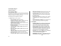
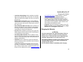
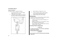
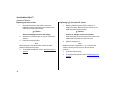
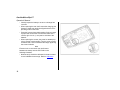
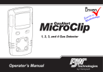
1, 2, 3, and 4-Gas Detector
Operator’s Manual
Limited Warranty and Limitation Liability
BW Technologies LP (BW) warrants the product to be free from defects in material and workmanship under normal use and service for a period of
two years, beginning on the date of shipment to the buyer. This warranty extends only to the sale of new and unused products to the original buyer.
BW’s warranty obligation is limited, at BW’s option, to refund of the purchase price, repair or replacement of a defective product that is returned to
a BW authorized service center within the warranty period. In no event shall BW’s liability hereunder exceed the purchase price actually paid by the
buyer for the Product.
This warranty does not include:
a) fuses, disposable batteries or the routine replacement of parts due to the normal wear and tear of the product arising from use;
b) any product which in BW’s opinion, has been misused, altered, neglected or damaged, by accident or abnormal conditions of operation,
handling or use;
c) any damage or defects attributable to repair of the product by any person other than an authorized dealer, or the installation of unapproved
parts on the product; or
The obligations set forth in this warranty are conditional on:
a) proper storage, installation, calibration, use, maintenance and compliance with the product manual instructions and any other applicable
recommendations of BW;
b) the buyer promptly notifying BW of any defect and, if required, promptly making the product available for correction. No goods shall be
returned to BW until receipt by the buyer of shipping instructions from BW; and
c) the right of BW to require that the buyer provide proof of purchase such as the original invoice, bill of sale or packing slip to establish that the
product is within the warranty period.
THE BUYER AGREES THAT THIS WARRANTY IS THE BUYER ’S SOLE AND EXCLUSIVE REMEDY AND IS IN LIEU OF ALL OTHER WARRANTIES, EXPRESS OR IMPLIED,
INCLUDING BUT NOT LIMITED TO ANY IMPLIED WARRANTY OF MERCHANTABILITY OR FITNESS FOR A PARTICULAR PURPOSE. BW SHALL NOT BE LIABLE FOR ANY
SPECIAL, INDIRECT, INCIDENTAL, OR BASED ON CONTRACT, TORT OR RELIANCE OR ANY OTHER THEORY.
Since some countries or states do not allow limitation of the term of an implied warranty, or exclusion or limitation of incidental or consequential
damages, the limitations and exclusions of this warranty may not apply to every buyer. If any provision of this warranty is held invalid or
unenforceable by a court of competent jurisdiction, such holding will not affect the validity or enforceability of any other provision.
Contacting BW Technologies by Honeywell
USA: 1-888-749-8878
Europe: +44(0) 1295 700300
Canada: 1-800-663-4164
Other countries: +1-403-248-9226
Email us at: [email protected]
Visit BW Technologies by Honeywell’s website at: www.gasmonitors.com
GasAlertMicroClip XT
Introduction
The operator’s manual provides basic information for the
GasAlertMicroClip XT. For complete operating instructions,
refer to the GasAlertMicroClip XT Technical Reference Guide
provided on the CD-ROM. The GasAlertMicroClip XT (“the
detector”) warns of hazardous gas at levels above user-defined
alarm setpoints. The detector is a personal safety device. It is
your responsibility to respond properly to the alarm.
Note
The detector is shipped with English as the default
displayed language. Additional languages provided are
Portuguese, Spanish, German, and French. The screens
for the additional languages are displayed on the detector
and in the corresponding operator’s manuals.
Zeroing the Sensors
To zero the sensors, refer to steps #1-3 in Calibration on page 7.
ec Warning
This instrument contains a lithium polymer battery. Dispose
of lithium cells immediately. Do not disassemble and do not
dispose of in fire. Do not mix with the solid waste stream.
Spent batteries should be disposed of by a qualified
recycler or hazardous materials handler.
Safety Information - Read First
Use the detector only as specified in this manual and the reference guide, otherwise the protection provided by the detector
may be impaired. Read the following cautions before using the
detector.
a Cautions
• Warning: Substitution of components may impair
Intrinsic Safety.
• Caution: For safety reasons, this equipment must be
operated and serviced by qualified personnel only.
Read and understand the user manual completely
before operating or servicing.
• Charge the detector before first time use. BW
recommends the detector be charged after every
workday.
• Before using the detector, refer to Sensor Poisons and
Contaminants.
1
GasAlertMicroClip XT
Operator’s Manual
• Calibrate the detector before first-time use and then
on a regular schedule, depending on use and sensor
exposure to poisons and contaminants. BW
recommends calibrating at least once every 180 days
(6 months).
• Caution: High off-scale readings may indicate an
explosive concentration.
• The combustible sensor is factory calibrated to 50%
LEL methane. If monitoring a different combustible
gas in the %LEL range, calibrate the sensor using
the appropriate gas.
• Extended exposure of the GasAlertMicroClip XT to
certain concentrations of combustible gases and
air may stress a detector element that can seriously
affect its performance. If an alarm occurs due to a
high concentration of combustible gases, calibrate
the detector. If necessary, replace the sensor.
• Only the combustible gas detection portion of this
instrument has been assessed for performance by
CSA International.
• Calibrate only in a safe area that is free of hazardous
gas and in an atmosphere of 20.9% oxygen.
• It is recommended that the combustible sensor be
checked with a known concentration of calibration
gas after any exposure to contaminants/poisons such
as, sulfur compounds, silicon vapors, halogenated
compounds, etc.
• BW recommends to bump test the sensors before each
day’s use to confirm their ability to respond to
gas by exposing the detector to a gas concentration
that exceeds the alarm setpoints. Manually verify that
the audible and visual alarms are activated. Calibrate
if the readings are not within the specified limits.
2
• Any rapid up scaling reading followed by a declining
or erratic reading may indicate a gas concentration
beyond the upper scale limit, which can be hazardous.
• Protect the combustible sensor from exposure to lead
compounds, silicones, and chlorinated hydrocarbons.
• Sensor exposure to certain organic vapors (such as
leaded gasoline and halogenated hydrocarbons) may
temporarily inhibit sensor performance. After exposure,
a bump test or calibration is recommended.
• For use only in potentially explosive atmospheres
where oxygen concentrations do not exceed
20.9% (v/v).
GasAlertMicroClip XT
Parts of the GasAlertMicroClip XT
Parts of the GasAlertMicroClip XT
Item
Description
1
IntelliFlash
2
Visual alarm indicators (LEDs)
3
Alligator clip
4
Charging connector / IR interface
5
Pushbutton
6
Carbon monoxide (CO) sensor
7
Hydrogen sulfide (H2S) sensor
8
Oxygen (O2) sensor
9
Combustible (LEL) sensor
10
Audible alarm
11
Liquid crystal display (LCD)
3
GasAlertMicroClip XT
Operator’s Manual
Display Elements
Item
1
8
2
7
3
6
5
4
4
Description
1
Alarm condition
2
Automatically zero sensor
3
Numeric value
4
Stealth mode
5
Battery life indicator
6
Gas identifier bars
7
Gas cylinder
8
Automatically span sensor
GasAlertMicroClip XT
Pushbuttons
Pushbuttons
Pushbutton
Description
• To activate the detector, press C.
• To deactivate the detector, press and hold C until the OFF countdown is complete and the LCD
deactivates.
• To view the TWA, STEL, and MAX (maximum) readings, press C twice. To clear the TWA, STEL,
and MAX readings, press C when the LCD displays RESET.
C
• To initiate calibration, deactivate the detector. Press and hold C while the detector performs the
OFF countdown. Continue holding C while the LCD briefly deactivates and then begins the CAL
countdown. Release C when the CAL countdown is complete.
• To activate the backlight while in normal operation, press C.
• To acknowledge latched alarms, press C.
• To acknowledge a low alarm and disable the audible alarm, press C (if the Low Alarm Acknowledge option is enabled).
5
GasAlertMicroClip XT
Operator’s Manual
Sensor Poisons and Contaminants
Several cleaners, solvents, and lubricants can contaminate and
cause permanent damage to sensors. Before using cleaners,
solvents, and lubricants in close proximity to the detector sensors, read the following caution and table.
a Caution
Use only the following BW Technologies by Honeywell
recommended products and procedures:
• Use water based cleaners.
• Use non-alcohol based cleaners.
• Clean the exterior with a soft, damp cloth.
• Do not use soaps, polishes, or solvents.
Below are common products to avoid using around sensors.
Cleaners and Lubricants
•
•
•
•
•
•
6
Brake cleaners
Lubricants
Rust inhibitors
Window and glass cleaners
Dishsoaps
Citrus based cleaners
•
•
•
•
Alcohol based cleaners
Hand sanitizers
Anionic detergents
Methanol (fuels and antifreezes)
•
•
•
•
•
•
Silicone cleaners and protectants
Silicone based adhesives, sealants, and gels
Hand/body and medicinal creams containing silicone
Tissues containing silicone
Mold releasing agents
Polishes
•
•
•
•
Bug repellents and sprays
Lubricants
Rust inhibitors
Window cleaners
Silicones
Aerosols
GasAlertMicroClip XT
Calibration
Calibration
Procedure
a Caution
Calibrate only in a safe area that is free of
hazardous gas in an atmosphere of 20.9%
oxygen.
1. Press and hold C as the detector
performs the OFF countdown. Continue
holding C when the LCD briefly
deactivates.
Display
Procedure
Display
4. When K flashes, connect the gas
cylinder (refer to page 8) and apply gas
at a flow rate of 250-500 ml/min.
After a sufficient amount of gas has been
detected (approximately 30 seconds), the
detector beeps and
flashes
while the detector completes the
calibration.
2. The LCD then activates again and
performs the CAL countdown.
Continue holding C until the
countdown is complete to enter
calibration.
5. The LCD displays CAL DUE. Next, a
screen displays showing the number of
days remaining before calibration is due
for each sensor. The LCD then displays
the earliest calibration due date, as some
sensors require more frequent
calibrations.
3.
Note: Only use the calibration cap during the calibration
span process and for bump tests.
flashes while the detector
zeroes all of the sensors and calibrates
the oxygen sensor. If a sensor fails to
auto zero, it cannot be calibrated. When
auto zero is complete, the LCD displays
APPLY GAS.
Wind currents may cause false readings and poor calibrations.
Do not calibrate the detector during or immediately after
charging is complete.
7
GasAlertMicroClip XT
Operator’s Manual
Attach the Gas Cylinder to the Detector
8
GasAlertMicroClip XT
Bump Test
Bump Test
9
GasAlertMicroClip XT
Operator’s Manual
Alarms
Refer to the following table for information about alarms and corresponding screens. If Stealth mode is enabled, the audible and
visual alarms are disabled. Only the vibrator alarm activates.
Alarm
10
Display
Alarm
Low Alarm
• Slow siren
TWA Alarm
• Slow siren
• Slow alternating flash
• Slow alternating flash
• L and gas bar flash
• L and gas bar flash
• Vibrator alarm activates
• Vibrator alarm activates
High Alarm
• Fast siren
STEL Alarm
• Fast siren
• Fast alternating flash
• Fast alternating flash
• L and gas bar flash
• L and gas bar flash
• Vibrator alarm activates
• Vibrator alarm activates
Multi-Gas Alarm
• Alternating low and high alarm siren
and flash
Over Limit (OL) Alarm
• Fast siren and alternating flash
• L and gas bars flash
• Vibrator alarm activates
• Vibrator alarm activates
• OL displays
• L and gas bar flash
Display
GasAlertMicroClip XT
Alarms
Alarm
Sensor Alarm
• During startup
Error [sensor name] displays
• During normal operation
Err displays
Low Battery Alarm
• Sequence of 10 rapid sirens and
alternating flashes with 7 seconds
of silence in between (continues for
15 minutes)
•
and L flash, LOW BAT displays, and the vibrator alarm activates
• After 15 minutes of the Low Battery
alarm, the Automatic Shutdown
Alarm sequence begins
• OFF displays before deactivating
Display
Alarm
Display
Confidence Beep and IntelliFlash
• One beep and flash every second
Note: Confidence Beep and
IntelliFlash automatically
deactivate during low battery
alarm, self-test fail, calibration fail,
bump test fail, or an alarm event.
Automatic Shutdown Alarm
• Sequence of 10 rapid sirens and alternating flashes with 1 second of silence
in between (sequence reactivates
seven times)
• LOW BAT and L display, and
vibrator alarm activates
• OFF displays before deactivating
Note: Alarms can be set to latching or non-latching. To enable/disable
latching, select/deselect Latching Alarms in Fleet Manager II. Local
regulations may require a latching alarm.
If Low Alarm Acknowledge is enabled and a low alarm occurs, press C
to disable the audible alarm. The visual and vibrator alarms remain
activated. If the alarm escalates to a high, STEL, or TWA alarm, the
audible alarm reactivates.
11
GasAlertMicroClip XT
Operator’s Manual
User Options Menu
To modify the user options, connect the detector to the IR Link
adapter and open Fleet Manager II. Refer to the Fleet Manager
II Operator’s Manual for complete instructions.
The following are the available user options:
1. Sensors (H2S, CO, LEL, and O2)
• Sensor Disabled: Disables the sensor.
• Calibration Gas (ppm) / (%LEL) / (%O2): Defines the
calibration gas concentration for each sensor.
• Calibration Interval (days): Defines how often a calibration should be performed.
• Bump Interval (days): Defines how often a bump test
should be performed.
• Low Alarm (ppm) / (%LEL) / (%O2): Defines the low
alarm setpoint.
• High Alarm (ppm) / (%LEL) / (%O2): Defines the high
alarm setpoint.
• TWA Alarm (ppm): Defines the time-weighted average
(TWA) alarm setpoint. H2S and CO sensors only.
• STEL Alarm (ppm): Defines the short-term exposure
limit (STEL) alarm setpoint. H2S and CO sensors only.
12
• STEL Interval (minutes): Defines the short-term exposure limit (5-15 minutes). H2S and CO sensors only.
• Auto-Zero Startup: When enabled, the detector automatically zeros the H2S, CO, and LEL sensors during
the startup self-test.
• LEL By Volume CH4: When enabled, the LEL reading
is displayed as %vol., assuming a methane environment.
• O2 Auto-Calibration on Startup: When enabled, the O2
sensor is automatically calibrated during startup.
2. User Options
• Confidence Beep: When enabled, the detector beeps
once every second to verify the battery has sufficient
power to detect hazardous gas and emit an alarm.
Detector is shipped with Confidence Beep disabled.
• Latching Alarms: When enabled, the audible, visual,
and vibrator alarms persist during a high or low alarm
until the gas concentration is below the low alarm setpoint and has been acknowledged by pressing C.
• Safe Mode: When enabled, SAFE continuously displays
on the LCD when all gas concentrations are
normal or below the alarm setpoints.
• Stealth Mode: When enabled, the audible alarm, LEDs
and backlight are disabled.
displays on the LCD.
GasAlertMicroClip XT
Charging the Detector
• Low Alarm Acknowledge: When enabled, the audible
alarm can be disabled during a low alarm. The vibrator,
LEDs, and LCD remain enabled. For H2S, CO, and LEL
sensors only.
• Datalog Interval (seconds): Enter a value (5-120 seconds) to define how often a datalog is recorded. Datalog
interval cannot be defined with configuring the detector
with the IR Link.
• Force Calibration When Overdue: When enabled, the
detector automatically enters calibration during startup
for overdue sensors. If the sensors are not calibrated
immediately, the detector will deactivate.
• Cal Lock: When enabled, the sensors can only be calibrated using an IR device (IR Link with Fleet Manager II
or the MicroDock II base station).
• Force Bump When Overdue: When enabled, a bump
test is required if the sensor has exceeded its bump test
interval. If a successful bump test is not performed, the
detector will deactivate.
• IntelliFlash: When enabled, the green LED flashes to
provide continuous visual confirmation that the detector
is operating correctly.
IntelliFlash automatically deactivates during a low battery alarm, a self-test fail, a calibration fail, a bump test
fail, or during an alarm event. To define how often IntelliFlash occurs (1-60 seconds), refer to Confidence Beep
and IntelliFlash Interval. Default setting is 1 second.
Detector is shipped with IntelliFlash enabled.
• Confidence Beep and IntelliFlash Interval: Enter a
value (1-60 seconds) to define how often IntelliFlash
occurs and the detector beeps. Intelliflash and/or Confidence Beep must be enabled in order to define Confidence Beep and IntelliFlash Interval.
• Language: Select the language to display on the LCD:
English, Français (French), Deutsch (German), Español (Spanish), or Português (Portuguese).
Charging the Detector
a Warning
Only the manufacturer can replace the battery. Failure to
adhere to this caution can lead to fire and/or explosion.
Charge only in a safe area that is free of hazardous gas
and within temperatures of 0°C-45°C (32°F-113°F).
The charging adapter is specific to your region. Use of the
charging adapter outside your region will damage the
charger and the detector.
Do not calibrate during or immediately after charging.
13
GasAlertMicroClip XT
Operator’s Manual
To charge the battery, complete the following:
3.
Allow the battery to charge for 2-3 hours.
1.
Deactivate the detector. Insert the charging
adapter plug into an AC outlet.
4.
To reach full battery capacity, allow the battery
to fully charge and discharge three times.
2.
Connect the charging adapter to the detector
IR interface. Refer to the following illustration.
5.
Charge the battery after each workday.
Maintenance
To maintain the detector in good operating condition, perform
the following basic maintenance as required.
• Calibrate, bump test, and inspect the detector on a
regular schedule.
• Maintain an operations log of all maintenance, bump
tests, calibrations, and alarm events.
• Clean the exterior with a soft damp cloth. Do not use
solvents, soaps, or polishes.
Replacing a Sensor or Sensor Filter
a Warning
To avoid personal injury, use only sensors specifically
designed for the detector.
Use proper ESD handling practices.
a Caution
Ensure hands are clean or wear gloves before handling
components.
14
GasAlertMicroClip XT
Maintenance
To replace a sensor or sensor filter, refer to the following
illustration, table, and procedures.
Item
Description
1
Front shell
2
LEL sensor
3
PCB
4
PCB screws (2)
5
Rear shell
6
Machine screws (6)
7
Sealing rib
8
CO sensor
9
H2S sensor
10
O2 sensor
11
Sensor filter
1.
Deactivate the detector. On a clean surface, place the
detector face down.
2.
Remove the six machine screws from the rear shell.
Remove the back cover by lifting the top and the
bottom upwards simultaneously to prevent damaging
the charging pins.
15
GasAlertMicroClip XT
Operator’s Manual
Replacing the sensor filter
1.
Note the placement of the PCB to ensure it is
replaced correctly. Remove the two screws on the
PCB. Remove the PCB carefully.
1.
Note the placement of the PCB to ensure it is
replaced correctly. Remove the two screws on the
PCB. Remove the PCB carefully.
a Caution
a Caution
Ensure no damage occurs to the battery.
Ensure no damage occurs to the battery.
2.
Remove the old sensor filter. It may be stuck to the
sensors.
If the sensor filter is stuck to the sensors, remove and
replace the sensor filter into the front shell.
3.
Place the new sensor filter.
Note
When inserting a new sensor filter, ensure the black
gasket is facing the front shell.
4.
16
Replacing H2S, CO, and LEL sensor
To complete the detector, refer to Reassembling the
detector.
2.
Slide the sensors out.
Note
Detectors that are configured for 1, 2, or 3 gases may
contain a dummy sensor in one of the four sensor
locations.
3.
Insert the new sensor(s).
4.
To complete the detector, refer to Reassembling the
detector.
GasAlertMicroClip XT
Maintenance
Replacing the oxygen sensor
2.
Note
Detectors that are configured for 1, 2, or 3 gases may
contain a dummy sensor in one of the four sensor
locations.
1.
Gently remove the circular rigidified flex PCB atop the
sensor from the metal sensor posts. Take care not to
tear the flex cable.
Note the placement of the PCB to ensure it is
replaced correctly. Remove the two screws on the
PCB.
a Caution
Ensure no damage occurs to the battery.
3.
Lift the PCB straight up. The oxygen sensor will stay
in the front shell. Remove the sensor.
4.
On roughly the same spot on the front shell, place the
new sensor. Lower the PCB over the oxygen sensor.
5.
Ensure the purple plastic sensor post is inserted into
the clear plastic hole. Carefully replace the circular
rigidified flex PCB atop the metal sensor posts. Take
care not to tear the flex cable.
6.
Press down to secure the circular rigidified flex PCB
atop the metal sensor posts.
7.
To complete the detector, refer to Reassembling the
detector.
Reassembling the detector
• Verify the PCB is seated correctly and inserted exactly
as it was removed (sensors face the front shell).
Replace the two PCB screws.
17
GasAlertMicroClip XT
Operator’s Manual
• Visually inspect the battery to ensure no damage has
occurred.
• When replacing the rear shell, ensure the charging pins
(bottom of inside rear shell) are aligned with the corresponding holes on the PCB.
• Press the front and rear shells together firmly to ensure
a proper seal. Ensure the front and rear shell have a
uniform, tight 1/16 in. (1 mm) seal on all sides of the
detector.
• When replacing the screws, they must be seated properly to prevent cross threading. Turn the screw counterclockwise until a click is heard and then begin tightening
the screw clockwise.
Note
Ensure the rib on the interior rear shell inserts
between the battery and the PCB. Refer to the
following illustration.
• New sensor(s) should be calibrated. Activate the detector and calibrate the sensor(s). Refer to Calibration.
18
GasAlertMicroClip XT
Specifications
Specifications
Instrument dimensions: 11.25 x 6.00 x 2.89 cm
(4.4 x 2.4 x 1.1 in.)
O2 measuring principle: Capillary controlled concentration
sensor
Weight: 170 g (6.0 oz.)
Alarm conditions: TWA alarm, STEL alarm, low alarm, high
alarm, multi-gas alarm, over limit (OL) alarm, low battery alarm,
confidence beep, automatic shutdown alarm
Operating temperature: -20°C to +58°C (-4°F to +136°F),
+50°C to +58°C is certified by CSA International on the
combustible sensor with ±5% accuracy
Audible alarm: 95 dB at 30 cm (1 ft.) (100 dB typical) variable
pulsed beeper
Storage temperature: -40°C to +50°C (-40°F to +122°F)
Visual alarm: Red light-emitting diodes (LED)
Operating humidity: 0% to 95% relative humidity (non-condensing)
Display: Alphanumeric liquid crystal display (LCD)
Alarm setpoints: May vary by region and are user defined. All
setpoints automatically display during the startup self-test.
Backlight: Activates for 5 seconds when the pushbutton is
pressed and during an alarm condition
Self-test: Initiated during activation
Detection range:
Calibration: Automatic zero and automatic span
H2S: 0 - 100 ppm (1 / 0.1 ppm increments)
CO: 0 - 500 ppm (1 ppm increments)
O2: 0 - 30.0% vol. (0.1% vol. increments)
Combustible (LEL): 0 - 100% (1% LEL increments) or
0 - 5.0% v/v methane
Oxygen sensor: Automatic span on activation (enable/disable)
Sensor type:
H2S, CO, O2: Single plug-in electrochemical cell
Combustibles: Plug-in catalytic bead
User field options: Startup message, confidence beep, latching alarms, enable/disable safe display mode, oxygen measurement, combustible sensor measurement, sensor disable,
define calibration interval, force calibration, calibration lock,
force bump, define bump interval, bump due lock, stealth mode,
language selection, enable/disable automatic oxygen calibration, enable/disable auto zero at startup, define alarm setpoints,
define span concentration values, define STEL calculation
19
GasAlertMicroClip XT
Operator’s Manual
period, low alarm acknowledge, IntelliFlash, confidence beep,
and IntelliFlash interval
Battery operating time: 1 rechargeable lithium polymer
battery 10 hours (typical)
Year of manufacture: The detector's year of manufacture is
determined from the serial number. The second and third number after the first letter determines the year of manufacture.
E.g., KA410-001000 = 2010 year of manufacture
Approved batteries:
Approved batteries for GasAlertMicroClip XT:
Narada NL 503759 and BYD Type SL503759
Rechargeable battery
Lithium polymer -20°C ≤ Ta ≤ +50°C
Temperature code
T4
Battery charger: GasAlertMicroClip XT charging adapter
First-time charge: 2-3 hours
Normal charge: 2-3 hours
Warranty: 2 years including sensors
Approvals:
Approved by CSA to both U.S. and Canadian Standards
CAN/CSA C22.2 No. 157 and C22.2 152
ANS/UL - 913 and ANSI/ISA - S12.13 Part 1
CSA
Class I, Division 1, Group A, B, C, and D
20
ATEX
IECEx
CE 0539 g II 1 G Ex ia IIC T4 Ga
KEMA 06ATEX0056
EN 60079-0, EN 60079-11, and EN 60079-26
Ex ia IIC T4 Ga IECEx CSA 05.0015
IEC 60079-0, IEC 60079-11, IEC 60079-26
This equipment has been tested and found to comply with the limits
for a Class B digital device, pursuant to Part 15 of the FCC Rules
and ICES-003 Canadian EMI requirements. These limits are
designed to provide reasonable protection against harmful interference in a residential installation. This equipment generates, uses
and can radiate radio frequency energy and, if not installed and used
in accordance with the instructions, may cause harmful interference
to radio communications. However, there is no guarantee that interference will not occur in a particular installation. If this equipment
does cause harmful interference to radio or television reception,
which can be determined by turning the equipment off and on, the
user is encouraged to try to correct the interference by one or more
of the following measures:
• Reorient or relocate the receiving antenna.
• Increase the separation between the equipment and receiver.
• Connect the equipment into an outlet on a circuit different from
that to which the receiver is connected.
• Consult the dealer or an experienced radio/TV technician for
help.
iERP: 131474-L3
D6567/0 [English]
© BW Technologies 2010. All rights reserved.
Thank you for reading this data sheet.
For pricing or for further information, please contact us at our UK Office, using the details
below.
UK Office
Keison Products,
P.O. Box 2124, Chelmsford, Essex, CM1 3UP, England.
Tel: +44 (0)1245 600560
Fax: +44 (0)1245 808399
Email: [email protected]
Please note - Product designs and specifications are subject to change without notice. The user is responsible for determining the
suitability of this product.