1
User’s
Manual
DL9000 Series
Digital Oscilloscope
Serial Bus Signal Analysis Function
(The analysis features of I2C bus signal, CAN bus signal, LIN bus signal, SPI bus signal, and UART signal)
IM 701310-51E
7th Edition
Foreword
Thank you for purchasing a YOKOGAWA Digital Oscilloscope1 with the Serial Bus Signal
Analysis Function. This user’s manual describes the serial bus signal analysis feature.2
1 One of the following DL9000 Series digital oscilloscopes.
DL9040/DL9140/DL9240 Series
Digital Oscilloscopes
DL9500/DL9700 Series Digital
Oscilloscopes
DL9040, DL9040L, DL9140, DL9140L, DL9240, and
DL9240L
DL9050L, DL9510L, DL9705L, and DL9710L
2 Analyzable signal types vary depending on the installed options.
/F5 option
/F7 option
/F8 option
I2C bus signals, SPI bus signals, and UART signals
CAN bus signals, LIN bus signals, SPI bus signals, and UART signals
I2C bus signals, CAN bus signals, LIN bus signals, SPI bus signals, and
UART signals
For information about other features, operating procedures, and handling precautions of
the DL9000 Series, see the following manuals.
Manual Title
DL9040/DL9140/DL9240 Series
Digital Oscilloscope
User’s Manual
DL9500/DL9700 Series
Digital Oscilloscope
User’s Manual
DL9040/DL9140/DL9240 Series
Digital Oscilloscope
Communication Interface User’s Manual
(in CD)
DL9500/DL9700 Series
Digital Oscilloscope
Communication Interface User’s Manual
(in CD)
DL9000 Series Digital Oscilloscope/
SB5000 Series Vehicle Serial Bus Analyzer
Power Supply Analysis Function User’s
Manual
Notes
Manual No.
Description
IM 701310-01E Explains all features and procedures
of the DL9040/DL9140/DL9240 Series
excluding the communication features.
IM 701331-01E Explains all features and procedures of
the DL9500/DL9700 Series excluding the
communication features.
IM 701310-17E Explains the communication interface
features of the DL9040/DL9140/DL9240
Series.
IM 701331-17E Explains the communication interface
features of the DL9500/DL9700 Series.
IM701310-61E Explains the operating procedures of the
optional power supply analysis feature.
• This manual, IM 701310-51E 7th Edition, applies to DL9000 Series digital
oscilloscope with firmware version 4.40 or later.
If the most recent firmware version is not running on your DL9000 Series, not all of the
features described in this manual can be used.
You can check the firmware version of your DL9000 Series on the overview screen.
For instructions on how to open the overview screen, see section 18.4 in the User’s
Manual IM 701310-01E or IM 701331-01E.
To upgrade to the latest firmware version, go to the following Web page, and then
browse to the download page.
http://tmi.yokogawa.com/service-support/downloads/
• The contents of this manual are subject to change without prior notice as a result of
continuing improvements to the instrument’s performance and features. The figures
given in this manual may differ from the actual screen.
• Every effort has been made in the preparation of this manual to ensure the accuracy
of its contents. However, should you have any questions or find any errors, please
contact your nearest YOKOGAWA dealer.
• Copying or reproducing all or any part of the contents of this manual without the
permission of Yokogawa Electric Corporation is strictly prohibited.
7th Edition : April 2009 (YK)
All Rights Reserved, Copyright © 2005 Yokogawa Electric Corporation
IM 701310-51E
i
Trademarks
Revisions
ii
• Adobe, Acrobat, and PostScript are trademarks of Adobe Systems Incorporated.
• For purposes of this manual, the TM and ® symbols do not accompany their
respective trademark names or registered trademark names.
• Other company and product names are trademarks or registered trademarks of their
respective companies.
•
•
•
•
•
•
•
1st Edition:
2nd Edition:
3rd Edition:
4th Edition:
5th Edition:
6th Edition:
7th Edition:
September 2005
March 2006
December 2006
March 2007
August 2007
June 2008
April 2009
IM 701310-51E
Symbols and Notations Used in This Manual
Safety Markings
The following markings are used in this manual.
Note
Calls attention to information that is important for proper operation of
the instrument.
Notation Used in the Procedural Explanations
On pages that describe the operating procedures in chapters 2 through 4, the following
notations are used to distinguish the procedures from their explanations.
Procedure
Explanation
Carry out the procedure according to the step numbers. All
procedures are written with inexperienced users in mind; experienced
users may not need to carry out all the steps.
This section describes the setup items and the limitations regarding
the procedures.
Notation of User Controls
Panel/Soft Key Names and Menu Items Set in Boldface
Boldface type indicates the names of user-controlled panel keys, and soft key items and menu
items displayed on screen.
SHIFT+Panel Key
The SHIFT+Panel key means you will press the SHIFT key to turn ON the indicator of SHIFT key
and then press the panel key. The menu marked in purple above the pressed key appears on the
screen.
Rotary knob and SET
Rotary knob and SET key indicates selecting or setting parameters and entering values using the
rotary knob, the SET key, and other keys. For details on the procedure, see section 4.1 and 4.2
in the User’s Manual IM701310-01E or IM701331-01E.
Unit
IM 701310-51E
k: Denotes “1000.”
Example: 100 kS/s (sample rate)
K: Denotes “1024.”
Example: 720 KB (file data size)
iii
Contents
Symbols and Notations Used in This Manual .................................................................................. iii
Chapter 1
Chapter 2
Chapter 3
Chapter 4
Chapter 5
Overview of the Serial Bus Signal Analysis
1.1
1.2
1.3
1.4
1.5
Serial Bus Setup
2.1
2.2
Chapter 7
iv
Executing Serial Bus Signal Auto Setup........................................................................... 2-1
Sharing of the Serial Bus Signal’s Trigger, Analysis, Search Settings ............................. 2-7
Triggering
3.1
3.2
3.3
3.4
3.5
Triggering on an I2C Bus Signal ....................................................................................... 3-1
Triggering on a CAN Bus Signal......................................................................................3-11
Triggering on a LIN Bus Signal....................................................................................... 3-21
Triggering on a SPI Bus Signal ...................................................................................... 3-23
Triggering on a UART Signal .......................................................................................... 3-27
Analysis
4.1
4.2
4.3
4.4
4.5
4.6
Selecting the Serial Bus Signal and Displaying and Saving Analysis Results ................ 4-1
Analyzing an I2C Signal ...................................................................................................4-11
Analyzing a CAN Bus Signal and Performing Stuff Bit Computation ............................. 4-13
Analyzing a LIN Bus Signal ............................................................................................ 4-18
Analyzing a SPI Bus Signal ............................................................................................ 4-20
Analyzing an UART Signal ............................................................................................. 4-24
Search
5.1
5.2
5.3
5.4
5.5
5.6
Chapter 6
I2C Bus Signal .................................................................................................................. 1-1
CAN Bus Signal ................................................................................................................ 1-2
LIN Bus Signal .................................................................................................................. 1-4
SPI Bus Signal ................................................................................................................. 1-5
UART Signal ..................................................................................................................... 1-7
Selecting the Serial Bus Signal and Skip Mode, Executing the Search,
and Displaying the Results ............................................................................................... 5-1
Searching I2C Bus Signals ............................................................................................... 5-4
Searching CAN Bus Signals ............................................................................................5-11
Searching LIN Bus Signals ............................................................................................. 5-18
Searching SPI Bus Signals ............................................................................................ 5-26
Searching UART Signals ................................................................................................ 5-31
Messages
6.1
Messages ......................................................................................................................... 6-1
Commands
7.1
7.2
7.3
7.4
7.5
7.6
List of Commands ............................................................................................................ 7-1
ANALysis Group ............................................................................................................. 7-24
MATH Group................................................................................................................... 7-43
SEARch Group ............................................................................................................... 7-44
SERialbus Group ............................................................................................................ 7-79
TRIGger Group ............................................................................................................... 7-85
IM 701310-51E
Contents
Chapter 8
Specifications
8.1
8.2
8.3
8.4
8.5
I2C Bus Signal Analysis .................................................................................................... 8-1
CAN Bus Signal Analysis ................................................................................................. 8-2
LIN Bus Signal Analysis ................................................................................................... 8-3
SPI Bus Signal Analysis ................................................................................................... 8-4
UART Signal Analysis....................................................................................................... 8-5
Index
1
2
3
4
5
6
7
8
Index
IM 701310-51E
v
Chapter 1
1.1
Overview of the Serial Bus Signal Analysis
I2C Bus Signal
1
Trigger ►For the procedure, see section 3.1
A trigger can be activated under the following conditions.
• When a start condition is detected.
• When a Nack is detected.
• When the specified address pattern (7-bit address, 7-bit address + sub address, or
10-bit address) is met.
• When the data pattern is met or not met.
• When a specified general call address is detected.
Overview of the Serial Bus Signal Analysis
I2C Bus is an abbreviation for Integrated Circuit Bus. It is a bidirectional bus for
connecting ICs. By using this feature, you will be able to analyze data while displaying
I2C Bus signal waveforms. The I2C bus signal analysis feature consists of the following
three main features.
2
3
4
5
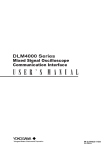
Address & Data Trigger Example
• When Activating a Trigger on the Start Condition or Address Pattern/Data Pattern
Start condition
Stop condition
Acknowledge bit
6
Data byte
Address + R/W bit
SDA
...
SCL
...
1 2 3 4 5 6 7 8 9
7
1 2 3 4 5 6 7 8 9
Trigger activated here
Nack Trigger Example
• When Activating a Trigger When the Acknowledge Bit Is Not Present
(When the SDA Signal is high)
Start condition
Stop condition
Acknowledge bit
Nack
present (H)
Data byte
Address + R/W bit
Acknowledge present (L)
SDA
...
SCL
...
1 2 3 4 5 6 7 8 9
8
Index
1 2 3 4 5 6 7 8 9
Trigger activated here
A trigger can be activated on the combination of the trigger conditions of the I2C bus
signal and analog signal (event interval trigger). For details on the event interval trigger,
see section 6.20 in the User’s Manual IM701310-01E or IM701331-01E.
Analysis ►For the procedure, see section 4.2
This feature analyzes the I2C bus signal data and shows a list of the analysis results.
There are two types of analysis result lists: simple and detail. The simple list displays the
analysis number, start and stop conditions, analysis data, address and data types, read/
write signal, and the status of the Acknowledge bit for each byte. The detail list displays
the time from the trigger position and data information in addition to the items displayed
by the simple list. The data of the detail list can be saved to an arbitrary storage medium
in CSV format. In addition, you can select an arbitrary byte in the analysis result list and
move the zoom position (the center of the zoom box) to the head of that byte.
Search ►For the procedure, see section 5.2
This feature searches for data that matches a specific address pattern, data pattern,
or Acknowledge bit status in the I2C bus signal data. When the search is executed, the
zoom box (ZOOM1 or ZOOM2) moves to the data position where the conditions are met,
and the data is displayed expanded in the zoom window.
IM 701310-51E
1-1
1.2
CAN Bus Signal
CAN stands for Controller Area Network. It is a serial communication protocol
standardized internationally by the ISO (International Organization for Standardization).
By using this feature, you will be able to analyze data while displaying signal waveforms
on the CAN bus as analog waveforms.
This CAN bus signal analysis feature consists of the following four main features.
Trigger ►For the procedure, see section 3.2
By setting the ID bit pattern, DLC, Data, and ACK slot status of the CAN bus, a trigger
can be activated on a specific data frame or remote frame. Up to four ID/Data conditions
can be specified allowing triggers to be activated on their OR conditions. In addition, the
SOF (Start of Frame) or error frame can be used as a trigger condition.
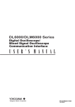
[Example] Standard Format of the Data Frame
Data frame
Arbitration field
CRC field
Data
CRC
sequence
4
8N (0≤N≤8)
15
ACK slot
DLC 3-0
ACK
ACK boundary
(1)
1 1 1
Data field
CRC boundary
11
RB0
IDE
1
RTR
SOF
ID 28-18
Control field
1 1 1
Recessive
EOF
7
Dominant
(2)
(3)
(4)
(5)
(1) Trigger point when the trigger condition is set to SOF
(2) Trigger point when the trigger condition is set only on the ID bit pattern
(3) Trigger point when the trigger condition is set on the ID bit pattern and DLC
(4) Trigger point when the trigger condition is set on the ID bit pattern and Data bit pattern
(5) Trigger point when the trigger condition is set to the ACK slot state
A trigger can be activated on the combination of the trigger conditions of the CAN bus
signal and analog signal (event interval trigger). For details on the event interval trigger,
see section 6.20 in the User’s Manual IM701310-01E or IM701331-01E.
Analysis ►For the procedure, see section 4.3
This feature analyzes the CAN bus signal data and shows a list of the analysis results.
There are two types of analysis result lists: simple and detail. The simple list displays the
analysis number, the type of analyzed frame, ID, Data, ACK slot status for each frame.
The detail list displays the time from the trigger position, DLC, and CRC sequence in
addition to the items displayed by the simple list. The data of the analysis result can be
saved to an arbitrary storage medium in CSV format.
You can select an arbitrary frame in the analysis results list and automatically display the
CAN bus signal for that frame (zoom link). The zoom position (the center of the zoom
box) can be moved to the head of a specified field of the frame (field jump).
Stuff Bit Computation ►For the procedure, see section 4.3
Stuff bits within the CAN bus signals can be detected, and stuff bit waveforms can be
displayed as math waveforms (stuff bit computation).
Search ►For the procedure, see section 5.3
A specific frame or field can be searched on the CAN bus signal data. When the search
is executed, the zoom box moves to the data position where the conditions are met, and
the data is displayed expanded in the zoom window (Zoom1 or Zoom2).
1-2
IM 701310-51E
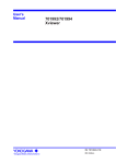
1.2 CAN Bus Signal
High-speed CAN (ISO11898) and Low-speed CAN (ISO11519-2)
High speed CAN (ISO11898)
Low speed CAN (ISO11519-2)
Transfer rate: 1 Mbps or less
Transfer rate: 125 kbps or less
Node n
(Max:30)
Node 1
CAN_High
120 Ω
CAN_Low
Node n
(Max:20)
Node 1
CAN_High
2.2 kΩ
120Ω
CAN_High
CAN_Low
Recessive
Dominant
Recessive
Bus level [V]
Bus level [V]
CAN bus physical signal
5
4
3
2
1
0
2
3
4
CAN_Low
2.2 kΩ
5
4
3
2
1
0
1
Overview of the Serial Bus Signal Analysis
Representative standards for the CAN physical layer are High-speed CAN (ISO 11898)
and Low-speed CAN (ISO 11519-2).
As shown in the following figure, the bus level is determined by the potential difference
between two buses, CAN_High and CAN_Low, in either standard.
CAN bus physical signal
CAN_Low
5
CAN_High
Recessive
Dominant
Recessive
6
Connecting the Probe
Probe to Be Used
A differential probe is used when measuring CAN bus signals.
Compatible differential probes:
701920, 701922, and 701924 by Yokogawa
7
When displaying the recessive voltage level higher than the dominant
voltage level (Recessive: H)
• For a two wire system (differential)
Connect the differential probe negative (–) to CAN_High, and the probe positive (+) to
CAN_Low.
• For a one wire system (single-ended)
Connect the differential probe negative (–) to CAN_High, and probe positive (+) to
GND (ground potential).
When displaying the recessive voltage level less than the dominant
voltage level (Recessive: L)
• For a two wire system (differential)
Connect the differential probe negative (–) to CAN_Low, and the probe positive (+) to
CAN_High.
• For a one wire system (single-ended)*
Connect the differential probe negative (–) to GND (ground potential), and probe
positive (+) to CAN_High.
*
IM 701310-51E
In this case, the passive probe (model 701943) can be connected to CAN_High.
1-3
8
Index
1.3
LIN Bus Signal
LIN stands for Local Interconnect Network. It is a serial communication protocol used
mainly for automobiles and other vehicles.
By using this feature, you will be able to analyze data while displaying signal waveforms
on the LIN bus as analog waveforms.
The LIN bus signal analysis feature consists of the following three main features.
Trigger ►For the procedure, see section 3.3
The trigger activates on the rising edge of the break delimiter. One of the following can
be selected for the bit rate: 19200 bps, 9600 bps, 4800 bps, 2400 bps, 1200 bps, or
User.
Trigger point
Break Field
Break
Delimiter
Synch Field
Protected Identifier
A trigger can be activated on the combination of the trigger conditions of the LIN bus
signal and CAN bus signal, or of the LIN bus signal and analog signal (event interval
trigger). For details on the event interval trigger, see section 6.20 in the User’s Manual
IM701310-01E or IM701331-01E.
Analysis ►For the procedure, see section 4.4
This feature analyzes the LIN bus signal data and shows a list of the analysis results.
There are two types of analysis result lists: simple and detail. The simple list displays the
analysis number, ID, Data, and Checksum status. The detail list displays the time from
the trigger position, ID field, ID parity error, and Checksum error in addition to the items
displayed by the simple list. The data of the analysis result can be saved to an arbitrary
storage medium in CSV format. You can select an arbitrary field in the analysis results
list and automatically display the LIN bus signal for that field (zoom link).
Search ►For the procedure, see section 5.4
You can search for a specific field on the LIN bus signal data. When the search is
executed, the zoom box moves to the data position where the conditions are met, and
the data is expanded in the zoom window (Zoom1 or Zoom2).
1-4
IM 701310-51E
1.4
SPI Bus Signal
1
Trigger ►For the procedure, see section 3.4
Acquires SPI Bus signals by comparing the specified conditions with the input signals at
the byte level (8 bits).
The data position to be compared can be specified in terms of the number of bytes from
the assertion of the chip select signal (CS). You can set two data patterns (Data 1 and
Data 2) for the four-wire SPI and one data pattern for the three-wire SPI. For Data 1 and
Data 2, a trigger is activated at the position where the latter data pattern matches.
An example is given below for the case when comparing Data 1 (3 bytes) from the 4th
byte after the assertion of the CS and comparing Data 2 (4 bytes) from the 10th byte
after the assertion of the CS and activating the trigger when both patterns match
Overview of the Serial Bus Signal Analysis
The SPI (Serial Peripheral Interface) Bus is a synchronized serial bus that is widely used
for inter-IC communications and data communications.
By using this feature, you will be able to analyze data while displaying the SPI Bus signal
waveform.
The SPI Bus signal analysis feature consists of the following three main features.
2
3
4
5
6
CS
4 bytes
Data1
0
1
2
3
1
2
1
Data2
0
1
2
3
1
2
1
F
E
A
8
1
6
7
4
5
F
F
F
F
4
7
10 bytes
1
1
CS: Active low
Data1 Condition:
Data Size:
Pattern:
Data Position:
Data2 Condition:
Data Size:
Pattern:
Data Position:
8
Trigger activated here
True
3
121
4
True
4
FFFF
10
Index
A trigger can be activated on the combination of the trigger conditions of the SPI bus
signal and analog signal (event interval trigger). For details on the event interval trigger,
see section 6.20 in the User’s Manual IM701310-01E or IM701331-01E.
IM 701310-51E
1-5
1.4 SPI Bus Signal
Analysis ►For the procedure, see section 4.5
This feature analyzes the SPI bus signal data and shows a list of the analysis results.
Analysis occurs in sync with the clock signal (Clock), in segments whose size is
determined by the field size (Field Size) and the enabled bit range (Enable MSB/LSB).
There are two types of analysis result lists: simple and detail. The simple list displays the
analysis number, Data 1/Data 2 (in hexadecimal notation), and CS status for each byte.
The detail list displays the time from the trigger position, the start and end positions of
the active period and Data 1/Data 2 (in binary notation) in addition to the items displayed
by the simple list. The data of the detail list can be saved to an arbitrary storage medium
in CSV format.
In addition, you can select an arbitrary byte in the analysis result list and move the zoom
position (the center of the zoom box) to the head of that byte.
Search ►For the procedure, see section 5.5
This feature searches for data that matches a specific data pattern in the SPI bus signal
data. When the search is executed, the zoom box moves to the data position where the
conditions are met, and the data is displayed expanded in the zoom window (Zoom1 or
Zoom2).
Analysis and Search Example
The table below indicates how the DL9000 analyzes or searches the signal shown in the
figure below differently depending on the Field Size and Enable MSB/LSB settings.
MSB
7 6
5
4
3
2
1
LSB
0
Data output signal (Data1)
1
1
0
0
1
0
0
0
Data input signal (Data2)
1
0
1
0
1
1
1
1
Clock signal(Clock)
Chip select signal (CS)
S
P
S: start condition
P: stop condition
Analysis and Search Conditions
• Data: Eight-bit Segment
• Bit order: MSB First
Analysis Conditions
Field Size Enable MSB/LSB
4bit
3 to 0
(4bit)
6bit
5 to 0
(6bit)
8bit
5 to 0
(6bit)
12bit
1-6
Analysis Results
Data1
Data2
C, 8
A, F
Analysis: The data is analyzed in two four-bit segments.
Search: The DL9000 searches for four bits from the
comparison start field.
3, 2
2, B
Analysis: The data is analyzed in one six-bit segment. (The
bits are split into one two-bit segment and one
four-bit segment.)
Search: The DL9000 searches for six bits from the
comparison start field.
0, 8
2, F
Analysis: The six least significant bits of one eight-bit
segment of the data are analyzed. (The bits are
split into one two-bit segment and one four-bit
segment.)
Search: The DL9000 searches for the least significant six
bits in an eight-bit segment from the comparison
start field.
Analysis and searching do not take place.
CS
L
L
L
IM 701310-51E
1.5
UART Signal
1
Trigger ►For the procedure, see section 3.5
Start
Bit
Data
7 bits (b0 to b6)
8 bits (b0 to b7)
3
5
Parity Stop
Bit
Bit
No parity bit if
NonParity is selected
6
The DL9000 Series digital oscilloscopes cannot trigger on the combination of UART
signals and other signals.
7
Analysis ►For the procedure, see section 4.6
This feature analyzes the UART signal data and shows a list of the analysis results.
There are two types of analysis result lists: simple and detail. The simple list displays the
analysis number, Data, and error status. The detail list displays the time from the trigger
position in addition to the items displayed by the simple list. The data of the analysis
result can be saved to an arbitrary storage medium in CSV format. You can select an
arbitrary data in the analysis results list and automatically display the UART signal for
that data (zoom link).
Search ►For the procedure, see section 5.6
This feature searches for data that matches a specific data pattern or error status in
the UART signal data. When the search is executed, the zoom box moves to the data
position where the conditions are met, and the data is displayed expanded in the zoom
window (Zoom1 or Zoom2).
IM 701310-51E
2
4
The trigger activates on the stop bit of all data frames. One of the following can be
selected for the bit rate: 115200bps, 57600bps, 38400bps, 19200bps, 9600bps,
4800bps, 2400bps, 1200bps, or User.
(Positive logic)
Overview of the Serial Bus Signal Analysis
Universal Asynchronous Receiver Transmitter (UART) is an integrated circuit that
performs serial-to-parallel conversion and parallel-to-serial conversion. UART is generally
used in inter-device communication such as with EIA RS-232.
By using this feature, you will be able to analyze data while displaying UART signal
waveforms.
The UART signal analysis feature consists of the following three main features.
1-7
8
Index
Chapter 2
2.1
Serial Bus Setup
Executing Serial Bus Signal Auto Setup
1
2
Procedure
ANALYSIS
XY
CURSOR
TELECOM TEST
PARAM
DISPLAY
ZOOM
INTENSITY
WINDOW 1
FORM
DISP 1
ZOOM 1
WINDOW 2
ACCUM CLEAR
ACCUM
DISP 2
ZOOM 2
MAG
Serial Bus Setup
MEASURE
SETUP
HELP
3
HISTORY CLEAR
HISTORY
Selecting a Serial Bus Signal and Executing Auto Setup
4
Selecting a Serial Bus Signal
1. Press SETUP.
2. Press the Serial Bus Setup soft key
5
The BUS SETUP menu and a dialog box appear.
3. Use the rotary knob and SET to select the Setup 1 or Setup 2 tab.
You can also press the Setup 1 or Setup 2 soft key.
6
7
8
Index
4. Use the rotary knob and SET to select the serial bus signal type from I2C to
UART.
IM 701310-51E
2-1
2.1 Executing Serial Bus Signal Auto Setup
5. Use the rotary knob and SET to set the items according to the selected serial
bus signal type.
The selectable sources vary depending on the serial bus signal type.
Items displayed on
CAN
the DL9500/DL9700
Series
I2C
Select the
source.
Select the SDA
and SCL sources.
LIN
SPI
Select the
source.
Items displayed
on the
DL9500/DL9700
Series
Select the wiring
system and the
CS, clock, and
data sources.
UART
Select the
source.
Executing Auto Setup
6. Use the rotary knob and SET to select Auto Setup Exec.
• The serial bus signal auto setup is executed. Auto Setup Exec changes to Auto Setup
Abort. To stop auto setup, select this using the rotary knob and SET.
• When you execute auto setup, a link will automatically be established between the trigger
feature and the serial bus setup that you select in step 3 (Setup 1 or Setup 2).
Note
You cannot execute auto setup when the serial bus signal type is set to SPI and the CS source
is set to None.
Undoing Auto Setup
7. Press the Undo soft key to set the settings back to the original values.
2-2
IM 701310-51E
2.1 Executing Serial Bus Signal Auto Setup
1
Adjusting the Settings after Auto Setup
8. Use the rotary knob and SET to adjust the items.
The adjustable items vary depending on the serial bus signal type.
I2C
2
CAN
Select this check box to set
any bit rate in the given
range.
Set the bit rate, level,
hysteresis, recessive level,
and sample point.
Set the level and
hysteresis of the SDA
and SCL sources.
3
4
SPI
LIN
5
Items displayed on the
DL9500/DL9700 Series
Set the bit rate, level,
hysteresis, sample point,
and revision.
6
Set the bit order.
UART
Select this check box to set
any bit rate in the given
range.
Set the bit rate, level,
hysteresis, sample point,
polarity, format, and bit
order.
7
Set the level, hysteresis, and
polarity of the CS, clock, and
data sources.
8
If you set the wiring system
to 3 wire, one Data item will
appear, because there is one
data source.
Index
Using a Short Cut to Move to the Trigger, Analysis, or Search Menu
9. Press the appropriate soft key from To SERIAL BUS TRIGGER to To SEARCH
to select the feature you want to set in more detail.
The respective feature menu appears. For a detailed explanation of each feature, see the
respective section indicated in “Explanation” in this section.
IM 701310-51E
Serial Bus Setup
Items displayed on the
DL9500/DL9700 Series
2-3
2.1 Executing Serial Bus Signal Auto Setup
Linking the Serial Bus Setup to the Trigger Feature
Carry out the step below to link the trigger feature to the serial bus setup.
Use the rotary knob and SET to set Trigger on to No Link, Setup 1, or Setup 2.
• If you select No Link, the link will be cut.
• If you select Setup 1 or Setup 2, the settings will be applied to the trigger settings.
Explanation
Some of the trigger, analysis, and search settings of the I2C, CAN, LIN, SPI, and UART
serial bus signals can be automatically set up.
If you execute auto setup and the DL9000 detects a serial bus signal, the trigger,
analysis, and search settings will automatically be set to values appropriate for the input
signal.
Settings Necessary for Auto Setup
• Source
Select source signals* on which to perform auto setup according to the serial bus
signal type.
I2C
CAN
LIN
SPI
UART
*
Select an SDA (serial data) source and an SCL (serial clock) source.
If you set the Select box to Analog, select from CH1 to CH4.
If you set the Select box to Logic, select from A0 to A7, from B0 to B7, from C0 to C7, or
from D0 to D7 (from A0 to A7 or from C0 to C7 on the DL9505L/DL9510L).
Select a source from CH1 to CH4.
Select a source from CH1 to CH4, from A0 to A7, from B0 to B7, from C0 to C7, or from D0
to D7 (from CH1 to CH4, from A0 to A7, or from C0 to C7 on the DL9505L/DL9510L).
Select a CS (chip select) source, a clock source, and a data source.
If you set the Select box to Analog, select from CH1 to CH4.
If you set the Select box to Logic, select from A0 to A7, from B0 to B7, from C0 to C7, or
from D0 to D7 (from A0 to A7 or from C0 to C7 on the DL9505L/DL9510L).
Select a source from CH1 to CH4, from A0 to A7, from B0 to B7, from C0 to C7, or from D0
to D7 (from CH1 to CH4, from A0 to A7, or from C0 to C7 on the DL9505L/DL9510L).
If you select a source from A0 to A7, from B0 to B7, from C0 to C7, or from D0 to D7, set the
threshold level. For the setup procedure, see section 5.18 in the User’s Manual
IM701331-01E.
If you select a source from M1 to M4, you will not be able to execute auto setup.
• Wiring System
Select the wiring system only in the case of an SPI serial bus signal.
3 wire
4 wire
One data line
Two data lines
Executing Auto Setup
If the DL9000 detects a serial bus signal, the trigger, analysis, and search settings will
automatically be set to values appropriate for the input signal.
• If you select Setup 1 and execute auto setup, the settings in Decode Setup in the
WINDOW 1 menu (Analysis 1) and the settings in Search Setup in the ZOOM 1 menu
(Search 1) are set to the serial bus signal’s type, source, and detection value (see
the next page). The same holds true for Setup 2, the settings in Decode Setup in the
WINDOW 1 menu (Analysis 2), and the settings in Search Setup in the ZOOM 2 menu
(Search 2).
If you execute auto setup using Setup 1 or Setup 2, the trigger settings are also
changed accordingly.
For details on the settings that are shared by auto setup, trigger, analysis, and search
features, see section 2.2.
• The “Trigger on” box at the bottom of the dialog box displays the auto setup name
(Setup 1 or Setup 2) that has been executed.
2-4
IM 701310-51E
2.1 Executing Serial Bus Signal Auto Setup
• For details on the trigger feature, see chapter 3. For details on the analysis and search
features, see chapters 4 and 5.
• An error message will appear if the DL9000 fails to detect a serial bus signal.
1
• Center Position after Auto Setup
The center position after auto setup will be 0 V.
2
• Waveforms That Were Displayed before Auto Setup
If you execute auto setup, data in the acquisition memory will be overwritten, and
waveforms that were displayed before auto setup will be cleared.
Serial Bus Setup
3
Undoing Auto Setup
You can revert to the settings before auto setup by pressing the Undo soft key. However,
you cannot undo auto setup if you turn OFF the power, because the settings before auto
setup will be discarded.
Items That Are Set to Default Values and Items That Are Set to Detected
Values
When you execute auto setup, the items are set to default values or set to values that are
detected from the signal as shown in the following table. Items that are not in the table
maintain their current values.
I2C
Items set to default
values
Items that are set to
detected values
CAN
Items set to default
values
Items that are set to
detected values
LIN
Items set to default
values
Items that are set to
detected values
SPI
Items set to default
values
Items that are set to
detected values
UART
Items set to default
values
Items that are set to
detected values
IM 701310-51E
SOF
0.6div
62.5%
Mode
Hysteresis
Sample point
Bit rate
Source level
Revision
Break
0.6div
50.0%
Hysteresis
0.6div
7
8
Index
CS, clock, and data source levels
Mode
Hysteresis
Sample point
Bit rate
Source level
Polarity
5
6
Mode
Every Start
Hysteresis
0.6div
Qualification
Don’t care
SDA and SCL source levels
Mode
Hysteresis
Sample point
Bit rate
Source level
Recessive level
4
Every Data
0.6div
50.0%
2-5
2.1 Executing Serial Bus Signal Auto Setup
Signals That Auto Setup Can Be Used
Auto setup is possible on a serial bus signal when the following conditions are met.
Voltage
Bit rate
Frames
Amplitude greater than or equal to 200 mV (when the probe attenuation is set
to 1:1)
Greater than or equal to 1200 bps
At least 5 frames over 10 seconds
Note
•
•
Measurement will only be correct if the probe attenuation ratio is set properly. Be sure to set
the probe attenuation ratio properly before executing auto setup. For the setup procedure,
see section 6.6 in the User’s Manual IM701310-01E or IM701331-01E.
If you select a source from A0 to A7, from B0 to B7, from C0 to C7, or from D0 to D7, the
voltage amplitude must exceed the threshold level. For operating instructions, see section
5.18 in the User’s Manual IM701331-01E.
Adjusting Settings after Auto Setup
You can adjust the items according to the serial bus signal type. For the selectable
ranges, see the referenced sections.
I2C
CAN
LIN
SPI
UART
SDA and SCL source levels and hysteresis
See “Explanation” in section 4.2.
Source signal’s bit rate, level, hysteresis, recessive level, and sample point
See “Explanation” in section 4.3.
Source signal’s bit rate, level, hysteresis, sample point, and revision
See “Explanation” in section 4.4.
Bit order; CS, clock, and data source levels, hysteresis, and polarities
See “Explanation” in section 4.5.
Source signal’s bit rate, level, hysteresis, sample point, polarity, format, and bit order
See “Explanation” in section 4.6.
Trigger, Analysis, and Search Features
For the procedure on how to use the trigger, analysis, and search features, see the
referenced sections below.
I2C
CAN
LIN
SPI
UART
Trigger
Section 3.1
Section 3.2
Section 3.3
Section 3.4
Section 3.5
Analysis
Section 4.2
Section 4.3
Section 4.4
Section 4.5
Section 4.6
Search
Section 5.2
Section 5.3
Section 5.4
Section 5.5
Section 5.6
Linking the Auto Setup, Analysis, and Search Settings to the Trigger
Feature
To share auto setup, analysis, and search settings with the trigger feature, you must link
the trigger feature to the auto setup.
• If you execute auto setup, a link will automatically be established to Setup 1 or Setup 2,
whichever auto setup that you executed.
• If you select No Link, the settings will not be linked between the trigger feature and the
auto setup, analysis, and search features.
For details, see section 2.2.
2-6
IM 701310-51E
2.2
Sharing of the Serial Bus Signal’s Trigger,
Analysis, Search Settings
1
The DL9000 shares the trigger, analysis, and search settings. If you change a setting in
one feature, the corresponding setting will also change in the other features.
• How Auto Setup Affects Analysis and Search Settings
• If you select Setup 1 and execute auto setup, the settings in Decode Setup in the
WINDOW 1 menu (Analysis 1) and the settings in Search Setup in the ZOOM 1
menu (Search 1) will be set to the serial bus signal’s type, source, and detection
value (see the page 2-5). The same holds true for Setup 2, the settings in Decode
Setup in the WINDOW 1 menu (Analysis 2), and the settings in Search Setup in the
ZOOM 2 menu (Search 2).
• How Auto Setup Affects Trigger Settings
• If you select Setup 1 and execute auto setup, the trigger settings (SERIAL BUS
menu under TRIGGER) will be set to the serial bus signal’s type, source, and
detected values (see page 2-5). At the same time, the Trigger on box at the bottom
of the Bus Setup dialog box will display the auto setup name Setup 1. The same
holds true for Setup 2.
• If you select Setup 1 from the Trigger on list, the trigger settings will be set to the
auto setup 1 settings. The same holds true for Setup 2.
Bus Setup
dialog box
Auto setup 1
(Setup 1 in the BUS
SETUP menu)
Serial Bus Setup
How Auto Setup Affects Trigger, Analysis, and Search Settings
2
3
4
5
6
7
8
Auto setup 2
(Setup 2 in the BUS
SETUP menu)
Index
Analysis 1
(Decode Setup in the
WINDOW 1 menu)
Search 1
(Search Setup in the
ZOOM 1 menu)
Triggering
(TRIGGER in the
SERIAL BUS menu)
Analysis 2
(Decode Setup in the
WINDOW 2 menu)
Search 2
(Search Setup in the
ZOOM 2 menu)
How Analysis and Search Settings Affect Auto Setup and Trigger Settings
• How Analysis and Search Settings Affect Auto Setup Settings
If you change settings for Analysis 1 or Search 1, the corresponding settings in auto
setup 1 will change. The same holds true for Analysis 2 and Search 2.
• How Analysis and Search Settings Affect Trigger Settings
• If Setup 1 is selected in the Trigger on list and you change the settings for Analysis
1 or Search 1, the corresponding trigger settings will change. Changing the settings
for Analysis 2 or Search 2 will not affect the trigger settings. Likewise, If Setup 2 is
selected in the Trigger on list and you change the settings for Analysis 2 or Search 2,
the corresponding trigger settings will change. Changing the settings for Analysis 1
or Search 1 will not affect the trigger settings.
• If No Link is selected in the Trigger on list, changing the settings for Analysis 1 or 2
or for Search 1 or 2 will not affect the trigger settings.
IM 701310-51E
2-7
2.2 Sharing of the Serial Bus Signal’s Trigger, Analysis, Search Settings
How Trigger Settings Affect Auto Setup, Analysis, and Search Settings
• If Setup 1 is selected in the Trigger on list and you change the trigger settings, the
corresponding Auto Setup 1, Analysis 1, and Search 1 settings will change. Auto
Setup 2, Analysis 2, and Search 2 settings will not be affected. Likewise, If Setup 2 is
selected in the Trigger on list and you change the trigger settings, the corresponding
Auto Setup 2, Analysis 2, and Search 2 settings will change. Auto Setup 1, Analysis 1,
and Search 1 settings will not be affected.
• If No Link is selected in the Trigger on list, changing the trigger settings will not affect
any of the Auto Setup, Analysis, and Search settings.
Note
Even if Setup 1 or Setup 2 is selected in the Trigger on list, if you select a trigger type other
than I2C, CAN, LIN, SPI, or UART, the Trigger on list will be set to No Link. In particular, Trigger
on will change to No Link if
• You select TV or Serial in the ENHANCED menu under TRIGGER.
• You press EDGE/STATE, WIDTH, or EVENT INTERVAL on the front panel.
Common Items
The table below indicates the shared serial bus signal items by trigger type.
Trigger Type
Trigger type (Type)
Source
Bit rate (Bitrate)
Level
Hysteresis (Hys)
Sample point
Recessive level
Revision
Polarity/active
Bit order
Wiring system (Mode)
Format
Parity
I2C
CAN
LIN
SPI
Changes to the selected trigger type menu.
Yes
Yes
Yes
Yes
No
Yes
Yes
No
Yes
Yes
Yes
Yes
Yes
Yes
Yes
Yes
No
Yes
Yes*
No
No
Yes
No
No
No
No
Yes*
No
No
No
No
Yes
No
No
No
Yes
No
No
No
Yes
No
No
No
No
No
No
No
No
UART
Yes
Yes
Yes
Yes
Yes*
No
No
Yes
Yes*
No
Yes
Yes*
Yes: Shared item; No: Item not available
* The trigger feature does not have a setup menu.
Note
When a setup data file is loaded, the way in which the loaded settings are applied to the items
shared among different serial bus trigger types varies depending on the firmware version as
follows:
• On products with firmware version earlier than 4.20, the level and hysteresis settings are
stored separately for Analysis 1, Search 1, Analysis 2, and Search 2 to the setup data file.
If you load this file into a product with firmware version 4.20 or later, the Analysis 1 settings
are applied to Analysis 1 and Search 1 settings, and the Analysis 2 settings are applied to
the Analysis 2 and Search 2 settings.
• On a product with firmware version earlier than 4.20, the Analysis 2 and Search 2 settings
shown in the following table are saved separately to the setup data file. If this file is loaded
into a product with firmware version 4.20 or later, the Analysis 2 settings are applied to
the Analysis 2 and Search 2 settings. The Analysis 1 and Search 1 settings shown in the
following table are the same regardless of the firmware version.
I2C
CAN
LIN
SPI
2-8
SDC and SCL sources
Bit rate, sample point, recessive level, and source
Bit rate and source
Mode, bit order, and CS, clock, and data source levels
IM 701310-51E
Chapter 3
3.1
Triggering
Triggering on an I2C Bus Signal
1
2
Procedure
3
Triggering
4
5
1. Press ENHANCED.
2. Press these soft keys: Type > I2C > Setup.
The Setup dialog box appears.
6
Selecting the Mode
3. Use the rotary knob and SET to select the Condition tab.
You can also press the Condition soft key to select the tab.
7
8
Index
4. Use the rotary knob and SET to select the mode from Every Start to Start Byte/
HS Mode.
Proceed to the steps on the pages indicated below according to the selected mode.
• Every Start: Step 10 on page 3-4
• ADR & DATA: Step 5 on page 3-2
• NON ACK: Step 5 on page 3-3
• General Call: Step 6 on page 3-3
• Start Byte/HS Mode: Step 8 on page 3-3
IM 701310-51E
3-1
3.1 Triggering on an I2C Bus Signal
When the Mode Is ADR & DATA
• Setting the Address Trigger Condition
5. Use the rotary knob and SET to select the address type from 7bit Address to
10bit Address.
6. Use the rotary knob and SET to set the address pattern to compare with.
You can also set the address pattern by selecting Detail to open a dialog box and use the
rotary knob and SET and soft keys. When you are done setting the address pattern,
press ESC to return to the previous screen.
Hexadecimal
Binary
Set the address pattern
(hexadecimal)
• Setting the Data Trigger Condition
7. Use the rotary knob and SET to set the mode to ON or OFF.
Select ON to enable the trigger condition. Select OFF to disable the trigger condition.
If you select OFF, proceed to step 10 on page 3-4.
8. Use the rotary knob and SET to set the condition to True or False, set Pos Mode
to X or Select, and set the position and size.
9. Use the rotary knob and SET to set the data pattern to compare with.
You can also set the data pattern by selecting Detail to open a dialog box and use the
rotary knob and SET and soft keys. When you are done setting the data pattern, press
ESC to return to the previous screen.
Hexadecimal
Binary
Set the data pattern
(hexadecimal)
Proceed to step 10 on page 3-4.
3-2
IM 701310-51E
3.1 Triggering on an I2C Bus Signal
When the Mode Is NON ACK
5. Use the rotary knob and SET to select the Nack bits to ignore from Start Byte to
1
Read Access.
The Nack bits whose check box is selected will not be used as trigger conditions. The trigger
condition is met when the DL9000 detects any of the Nack bits whose check box is not
selected.
2
3
Triggering
4
Proceed to step 10 on page 3-4.
When the Mode Is General Call
5
• Setting the Second Byte Trigger Condition
6. Use the rotary knob and SET to select the second byte format from X to 7bit
Master Address.
6
If you select X, 0000 0100, or 0000 0110, proceed to step 10 on page 3-4.
7. Use the rotary knob and SET to set the address pattern to compare with.
You can also set the address pattern by selecting Detail to open a dialog box and use the
rotary knob and SET and soft keys. When you are done setting the address pattern,
press ESC to return to the previous screen.
7
8
Hexadecimal
Binary
Set the address pattern
(hexadecimal)
Index
• Setting the Data Trigger Condition
Set the trigger condition according to steps 7 to 9 on the previous page.
Proceed to step 10 on page 3-4.
When the Mode Is Start Byte/HS Mode
8. Use the rotary knob and SET to set the type (master code) to Start Byte or HS
Mode.
Proceed to step 10 on page 3-4.
IM 701310-51E
3-3
3.1 Triggering on an I2C Bus Signal
Setting the SDA, SCL, and Qualification
10. Use the rotary knob and SET to select the Source tab.
You can also press the Source soft key to select the tab.
If you a using the DL9040/DL9140/DL9240 Series, proceed to step 12.
11. Use the rotary knob and SET to set Select to Analog or Logic.
If you are using the DL9500/DL9700 Series, carry out this step.
Setting the SDA Source
12. Use the rotary knob and SET to select the SDA (serial data) source.
• On the DL9040/DL9140/DL9240 Series, select the source from CH1 to CH4.
• On the DL9500/DL9700 Series:
• If you selected Analog in step 11, select the source from CH1 to CH4.
• If you selected Logic in step 11, select the source from A0 to A7, from B0 to B7,
from C0 to C7, or from D0 to D7 (from A0 to A7 or from C0 to C7 on the DL9505L/
DL9510L).
Setting the SCL Source
13. Use the rotary knob and SET to select the SCL (serial clock) source.
• On the DL9040/DL9140/DL9240 Series, select the source from CH1 to CH4.
• On the DL9500/DL9700 Series:
• If you selected Analog in step 11, select the source from CH1 to CH4.
• If you selected Logic in step 11, select the source from A0 to A7, from B0 to B7,
from C0 to C7, or from D0 to D7 (from A0 to A7 or from C0 to C7 on the DL9505L/
DL9510L).
Setting the Qualification
14. Use the rotary knob and SET to set the logic to AND or OR.
15. Use the rotary knob and SET to set the state of signals other than those selected
for the SDA and SCL to H, L, or X.
On the DL9500/DL9700 Series, if you selected Logic in step 11, select Qualification. In the
dialog box that appears, use the rotary knob and SET to select H, L, or X. When you are
done setting the states, press ESC to return to the previous screen.
Setting the Trigger Level and Hysteresis
Set the trigger level and hysteresis if you are using the DL9500/DL9700 Series and you
selected Analog in step 11, or if you are using the DL9040/DL9140/DL9240 Series.
16. Use the rotary knob and SET to select Setup under Level/Hys.
The Level/Hys dialog box appears.
17. Use the rotary knob and SET to set the level and hysteresis for each source.
On the DL9040/DL9140/DL9240 Series
On the DL9500/DL9700 Series
When Analog is selected in step 11
When Logic is selected in step 11
You can select the
status of the CH1 to
CH4 signals except for
the channels selected
for SDA and SCL.
You can set the status of the A0 to A7, B0 to B7,
C0 to C7, and D0 to D7 signals (A0 to A7 and
C0 to C7 on the DL9505L/DL9510L) excluding
the signals that are assigned to SDA and SCL
sources.
3-4
IM 701310-51E
3.1 Triggering on an I2C Bus Signal
1
Explanation
2
2
This feature triggers on I C bus signals. The following figure shows the data format of I C
bus signals.
Start condition
Data byte
SDA
...
SCL
...
Mode
3
1 2 3 4 5 6 7 8 9
Triggering
1 2 3 4 5 6 7 8 9
2
Stop condition
Acknowledge bits
Address and R/W bits
4
2
Select the I C trigger mode from Every Start, ADR & DATA, NON ACK, General Call, and
Start Byte/HS Mode.
5
Every Start Mode
When a start condition is detected, the DL9000 triggers on the falling edge of the SDA
signal.
Start condition
6
SDA
7
SCL
Triggers here
8
ADR & DATA Mode
When the address and data values match, the DL9000 triggers on the falling edge of the
9th SCL signal clock.
Start condition
Address and R/W bits
Data byte
SDA
...
SCL
...
1 2 3 4 5 6 7 8 9
Index
Stop condition
Acknowledge bits
1 2 3 4 5 6 7 8 9
Triggers here
• Address
• You can set the address type to 7bit Address, 7bit + Sub Address, or 10bit Address.
• Set the address pattern in hexadecimal or binary notation. The address trigger
condition is met when the specified address pattern matches the input signal
address pattern.
•
•
IM 701310-51E
If you specify X, the condition is assumed to be met regardless of the corresponding bit
status.
If a binary pattern contains any Xs, the corresponding hexadecimal display will be “$.”
3-5
3.1 Triggering on an I2C Bus Signal
• Data
You can select whether or not to use the data pattern as a trigger condition.
• Comparison Condition
The data trigger condition is met when the result of comparing the input signal
pattern with the specified pattern meets the selected comparison condition.
True
False
When the patterns match
When the patterns don’t match
• Comparison Start Position
In the Pos Mode setting, you can set the comparison start point to the specified
point (Select) or don’t care (X). If you select Select, the DL9000 skips the specified
number of bytes and starts comparing from the next data byte.
Selectable range: 0 to 9999 bytes
• Data Size
Set how many consecutive data bytes you want to compare.
Selectable range: 1 to 4 bytes
• Data Pattern
Set the data pattern for the specified size in hexadecimal or binary notation.
•
•
If you specify X, the condition is assumed to be met regardless of the corresponding bit
status.
If a binary pattern contains any Xs, the corresponding hexadecimal display will be “$.”
• Example
This example displays the data sequence at the byte level (hexadecimal notation) and
indicates the trigger position. The following notations are used in the figure.
S: Start condition, P: Stop condition, Shading: Compared pattern
Trigger only on the address pattern
Mode
Address
Data
ADR & DATA
7bit address, A4
Mode: OFF
Address and R/W bits
S
A4
25
AE
57
27
FE
98
99
27
P
Matches the specified address pattern. Triggers here.
Trigger only on the data pattern
Mode
Address
Data
ADR & DATA
Don’t care
Mode: ON, Condition: True, Size: 2 bytes, Data pattern: 27 and AE
< Pos Mode: X >
Address and R/W bits
S
A4
27
AE
57
27
FE
98
99
27
P
2. Triggers here
1. Matches the specified size of data pattern (27 and AE)
< Pos Mode: Select, Position: 3 >
Address and R/W bits
S
A4
27
FE
57
27
AE
98
99
27
P
3. Triggers here
2. Matches the specified size of data
pattern (27 and AE)
1. Skips 3 bytes
3-6
IM 701310-51E
3.1 Triggering on an I2C Bus Signal
NON ACK Mode
The DL9000 triggers when the acknowledge bit is Nack (when the SDA signal is high).
You can select whether use or ignore the following acknowledge bits for triggering: start
byte, HS mode master code, and read access byte.
Start condition
Stop condition
Acknowledge bits
Data byte
Acknowledge (L)
Address and R/W bits
2
Nack(H)
...
SCL
...
3
Triggering
SDA
1 2 3 4 5 6 7 8 9
1
1 2 3 4 5 6 7 8 9
4
Triggers here
General Call Mode
The DL9000 triggers on the general call address (0000 0000).
• Second Byte
You can use the second byte address pattern (the byte after the general call address)
as a trigger condition. The second byte trigger condition is met when the specified
pattern matches the input signal pattern.
X
0000 0100
0000 0110
7bit Master Address
Not used as a trigger condition
When the input signal pattern matches the pattern 0000 0100 (0x04)
When the input signal pattern matches the pattern 0000 0110 (0x06)
When the input signal pattern matches the specified pattern
If you select 7bit Master Address, you can use the data pattern as
a trigger condition as described in the next section.
• Example
This example displays the data sequence at the byte level (hexadecimal notation) and
indicates the trigger position. The following notations are used in the figure.
S: Start condition, P: Stop condition, Shading: Compared pattern
Trigger only on the general call address
General Call
X
Address and R/W bits
S
00
27
AE
57
27
FE
98
99
27
P
2. Triggers here
1. Determines whether the first byte is a general call address
Trigger when the second byte address is 06
Mode
Second Byte
General Call
0000 0110
Address and R/W bits
S
00
06
AE
57
27
FE
98
99
27
P
3. Triggers here
2. Determines whether the address pattern is 06
1. Determines whether the first byte is a general call address
IM 701310-51E
6
7
8
• Data
The conditions and settings are the same as those explained on page 3-6. See the
respective item for details.
Mode
Second Byte
5
3-7
Index
3.1 Triggering on an I2C Bus Signal
Trigger when the second byte address matches the specified pattern
Mode
Second Byte
Data
General Call
7bit Master Address, address pattern: 1010 1011 (0xAB)
Mode: ON, Condition: True, Size: 2 bytes, Data pattern: 27 and AE
< Pos Mode: X >
Address and R/W bits
S
00
AB
27
AE
57
27
98
FE
99
P
4. Triggers here
3. Matches the specified data pattern (27 and AE)
2. Matches the specified address pattern (AB)
1. Determines whether the first byte is a general call address
< Pos Mode: Select, Position: 3 >
Address and R/W bits
S
00
AB
27
AE
57
27
AE
98
99
P
5. Triggers here
4. Matches the specified data pattern (27 and AE)
3. Skips 3 bytes
2. Matches the specified address pattern (AB)
1. Determines whether the first byte is a general call address
Start Byte/HS Mode
The DL9000 triggers on the start byte or the HS mode master code.
• Start Byte
The DL9000 triggers on a start byte (pattern: 0000 0001).
Start condition
Address and R/W bits
SDA
0 0 0 0 0 0 0 1
(Start byte)
Acknowledge bits
Stop condition
Data byte
...
...
SCL
1 2 3 4 5 6 7 8 9
1 2 3 4 5 6 7 8 9
Triggers here
• HS Mode
The DL9000 triggers on the HS (high-speed) mode master code (pattern: 0000 1XXX).
Start condition
Address and R/W bits
0 0 0 0 1 x x x
Acknowledge bits
Stop condition
Data byte
SDA
...
SCL
...
1 2 3 4 5 6 7 8 9
1 2 3 4 5 6 7 8 9
Triggers here
3-8
IM 701310-51E
3.1 Triggering on an I2C Bus Signal
• Example
This example displays the data sequence at the byte level (hexadecimal notation) and
indicates the trigger position. The following notations are used in the figure.
1
2
S: Start condition, P: Stop condition, Shading: Compared pattern
Trigger on a start byte
Mode
Type
Start Byte/HS Mode
Start byte
01
Sr
AE
57
27
FE
98
Triggers here
99
27
3
P
Triggering
S
Sr: Restart
4
SDA, SCL, and Qualification
SDA and SCL Sources
You can select the serial data (SDA) and serial clock (SCL) sources.
• On the DL9040/DL9140/DL9240 Series, select the sources from CH1 to CH4.
• On the DL9500/DL9700 Series, select the sources from CH1 to CH4, from A0 to A7,
from B0 to B7, from C0 to C7, or from D0 to D7 (from CH1 to CH4, from A0 to A7, or
from C0 to C7 on the DL9505L/DL9510L).
5
6
Trigger Level
You can set the I2C bus signal trigger level for CH1 to CH4 separately.
• The selectable range is 8 divisions within the screen. The resolution is 0.01 divisions.
For example, if the T/div setting is 2 mV/division, the resolution is 0.02 mV.
• You can reset the trigger level to the current offset voltage by pressing RESET.
• If the source is set to a signal from A0 to D7, the trigger level is the threshold level that
you set according to the instructions in section 5.18 of the User’s Manual
IM701331-01E.
Hysteresis
Specifies a hysteresis of approximately 0.3 divisions around the trigger level.*
Specifies a hysteresis of approximately 1 division around the trigger level.*
The values above are typical. They are not strictly warranted.
Qualification and Logic
• Qualification
Set the state of signals other than those selected for the SDA and SCL to H, L, or
X. This trigger requirement is called qualification requirement. The qualification
requirement is met when the selected state matches the input signal state.
H
L
X
*
IM 701310-51E
8
Index
Hysteresis specifies a voltage range above and below the trigger level to prevent the
DL9000 from triggering on minute voltage fluctuations.
*
7
When the input signal is high
When the input signal is low
Not used as a trigger condition (Don’t care)
The level for determining high or low is the trigger level that you set above when you set the
signal to a channel from CH1 to CH4. If the source is set to a signal from A0 to D7, the trigger
level is the threshold level that you set according to the instructions in section 5.18 of the
User’s Manual IM701331-01E.
3-9
3.1 Triggering on an I2C Bus Signal
• Logical Condition
You can select the logical condition for the qualification and the trigger condition for
the I2C bus signal that you set in each mode. When the logical condition is met, the
DL9000 triggers.
When the qualification and the I2C bus signal trigger condition are both met
When either the qualification or the I2C bus signal trigger condition is met
AND
OR
CH3 = L, CH4 = H, Logic = AND I2C bus signal trigger
condition met
.....
SDA
SCL
1
.....
.....
I2C bus signal trigger
condition met
.....
8
9
1
.....
8
9
CH3
CH4
Does not meet the qualification
No trigger here
Meets the qualification
Triggers here
Note
To trigger only on the I2C bus signal trigger condition (SDA and SCL signals), specify the
settings as follows:
• The state of signals other than those selected for the SDA and SCL: X (don’t care)
• Logic: AND
3-10
IM 701310-51E
3.2
Triggering on a CAN Bus Signal
1
2
Procedure
3
Triggering
4
5
1. Press ENHANCED.
2. Press these soft keys: Type > CAN > Setup.
The Setup dialog box appears.
6
Selecting the Mode
3. Use the rotary knob and SET to select the Condition tab.
You can also press the Condition soft key to select the tab.
7
8
Index
4. Use the rotary knob and SET to select the mode from SOF to ID/Data OR.
Proceed to the steps on the pages indicated below according to the selected mode.
• SOF: Step 12 on page 3-15
• Error Frame: Step 12 on page 3-15
• ID Std/Data: Step 5 on page 3-12
• ID Ext/Data: Step 5 on page 3-12
• ID/Data OR: Step 5 on page 3-14
IM 701310-51E
3-11
3.2 Triggering on a CAN Bus Signal
When the Mode Is ID Std/Data or ID Ext/Data
This section will explain the procedure using ID Std/Data mode as an example. The
procedure is the same for ID Ext/Data mode.
• Setting the ID Bit Pattern Trigger Condition
5. Use the rotary knob and SET to set the bit pattern to compare with.
You can also set the bit pattern by selecting Detail to open a dialog box and use the rotary
knob and SET and soft keys. When you are done setting the bit pattern, press ESC to
return to the previous screen.
Set the bit pattern
(hexadecimal)
Hexadecimal
Binary
• Setting the Frame Type Trigger Condition
6. Use the rotary knob and SET to select the Frame Type comparison condition
from Don’t care to Data.
If you select Don’t care or Remote, proceed to step 11 on page 3-13.
7. Use the rotary knob and SET to set the DLC.
• Setting the Data Trigger Condition
8. Use the rotary knob and SET to select the data comparison condition from Don’t
care to Out of Range.
• If you select Don’t care, proceed to step 11 on page 3-13.
• If you select a condition from Greater to Out of Range, proceed to step 10.
9. Use the rotary knob and SET to set the data pattern to compare with.
You can also set the data pattern by selecting Detail to open a dialog box and use the
rotary knob and SET and soft keys. When you are done setting the data pattern, press
ESC to return to the previous screen.
3-12
IM 701310-51E
3.2 Triggering on a CAN Bus Signal
1
10. Use the rotary knob and SET to set the data to compare in each entry box.
Set each item according to the comparison condition you selected in step 8.
Comparison
Condition
True, False
Greater/Equal,
Less/Equal
Between, Out
of Range
Setting
Byte Order
–
Sign
–
MSB/LSB
–
–
Yes
1
Yes
Yes
Yes
–
Yes2
Yes
Yes
Yes
Detail
Yes
Data(Dec)
–
Yes: Set, –: Not set
True, False
3
Triggering
• Detail: Data pattern (hexadecimal or binary)
• Data(Dec): Reference value (decimal)
1 Set one reference value.
2 Set two reference values to define a reference range. Set the lower limit in the left
entry box and the upper limit in the right entry box.
• Byte Order: Data order
• Sign: Signed or unsigned
• MSB/LSB: Most significant and least significant bit positions
Set the MSB in the left entry box and the LSB in the right entry box.
2
4
5
6
Hexadecimal
Binary
7
Set the data pattern
(hexadecimal)
8
Greater/Equal, Less/Equal
Index
Between, Out of Range
• Setting the ACK Trigger Condition
11. Use the rotary knob and SET to select the ACK condition from Don’t care to
NON ACK or ACK.
If you select Don’t care, it will not be used as a trigger condition.
Proceed to step 12 on page 3-15.
IM 701310-51E
3-13
3.2 Triggering on a CAN Bus Signal
When the Mode Is ID/Data OR
Setting the ID/Data 1 to ID/Data 4 Trigger Conditions
5. Use the rotary knob and SET to set ID/Data 1 to ON or OFF.
Select ON to enable the trigger condition. Select OFF to disable the trigger condition.
If you select OFF, proceed to step 10.
6. Use the rotary knob and SET to select ID/Data 1 Setup.
The ID/Data Setup dialog box appears.
7. Use the rotary knob and SET to set the format to Std or Ext.
8. Use the rotary knob and SET to set the ID, Frame Type, Data, and ACK trigger
conditions.
For the procedure to set each condition, see pages 3-12 and 3-13.
9. Press ESC to return to the previous screen.
10. Likewise, set ID/Data2 to ID/Data4 according to steps 5 to 9.
Proceed to step 12 on page 3-15.
3-14
IM 701310-51E
3.2 Triggering on a CAN Bus Signal
1
Setting the Source Bit Rate, Sample Point, Trigger Level, Hysteresis, and
Recessive Level
12. Use the rotary knob and SET to select the Source tab.
You can also press the Source soft key to select the tab.
2
Setting the Bit Rate and Sample Point
13. Use the rotary knob and SET to select the bit rate from 1Mbps to 33.3kbps.
3
Triggering
If you select the User check box, you will be able to set the bit rate from 10.0kbps to
1.000Mbps using the rotary knob and SET.
14. Use the rotary knob and SET to set the sample point to a value from 18.8 to
90.6%.
4
5
Setting the Trigger Level, Hysteresis, and Recessive Level
15. Use the rotary knob and SET to select the source from CH1 to CH4.
6
16. Use the rotary knob and SET to set the level and hysteresis.
17. Use the rotary knob and SET to set Recessive to H or L.
7
8
Index
IM 701310-51E
3-15
3.2 Triggering on a CAN Bus Signal
Explanation
This feature triggers on CAN bus signals. For details on the CAN bus signal frame
format, see page 3-20.
Mode
Set the CAN trigger mode to SOF, Error Frame, ID Std/Data, ID Ext/Data, or ID/Data OR.
SOF Mode
Triggers on the start of a CAN bus signal frame.
SOF: Start of Frame
Error Frame Mode
The DL9000 triggers when the error frame’s error flag is active.
ID Std/Data and ID Ext/Data Modes
ID Std/Data mode is used to trigger on the data frame or remote frame in standard
format.
ID Ext/Data mode is used to trigger on the data frame or remote frame in extended
format.
The DL9000 triggers on the AND logic of ID, Frame Type, Data, and ACK conditions.
The settings in ID Std/Data mode are shared with the settings in ID Ext/Data mode.
• ID
Set the ID bit pattern in hexadecimal or binary notation. The ID bit pattern is 11 bits in
standard format and 29 bits in extended format. The ID trigger condition is met when
the specified bit pattern matches the input signal ID bit pattern.
•
•
If you specify X, the condition is assumed to be met regardless of the corresponding bit
status.
If a binary pattern contains any Xs, the corresponding hexadecimal display will be “$.”
• Frame Type
The DL9000 can be configured to trigger on the remote frame or data frame.
• Selecting the Frame
A CAN bus signal frame contains a Remote Transmission Request (RTR) bit that
indicates whether the frame is a remote frame or a data frame. Select the frame
that the DL9000 will trigger on.
Don’t care
Remote
Data Frame
The DL9000 will trigger on both remote frames and data frames.
The DL9000 will trigger on remote frames.
The DL9000 will trigger on data frames.
If you select Don’t care or Remote, the DLC and Data trigger conditions in the next section
will be ignored.
• DLC (Data Length Code)
Set the data field length. The DLC trigger condition is met when the input signal
DLC value matches the reference value. Set this value only when the frame type is
set to Data Frame.
Selectable range: 0 to 8 bytes
If you set this value to zero, the data trigger conditions in the next section will be ignored.
3-16
IM 701310-51E
3.2 Triggering on a CAN Bus Signal
• Data
You can use the Data Field value as a trigger condition. Set this value only when the
frame type is set to Data Frame.
• Comparison Condition
The data trigger condition is met when the result of comparing the input signal Data
Field value with the reference value meets the selected comparison condition.
Out of Range
Not used as a trigger condition
When the input signal value meets the reference value
When the input signal value does not match the reference value
When the input signal value is greater than or equal to the reference value
When the input signal value is less than or equal to the reference value
When the input signal value is within the reference range that includes the
boundary reference values
When the input signal value is outside the reference range that excludes the
boundary reference values
• Data Pattern
Set the data pattern for the length specified by DLC in hexadecimal or binary
notation. The data pattern is valid only when the comparison condition is set to True
or False.
•
•
If you specify X, the condition is assumed to be met regardless of the corresponding bit
status.
If a binary pattern contains any Xs, the corresponding hexadecimal display will be “$.”
• Reference Value Data(Dec)
• If you set the comparison condition to Greater/Equal or Less/Equal, set one
reference value.
• If you select Between or Out of Range, set two reference values to define a
reference range. The values are automatically adjusted so that the lower limit is
less than or equal to the upper limit.
• If the comparison condition is True or False, the data pattern is used as the
reference value.
• Selectable range
Set the selectable range in decimal notation.
Unsigned
Signed
0 to 9E+18
The selectable maximum value is limited by the data length and bit position
that are determined by the DLC and MSB/LSB settings, respectively.
–9E+18 to 9E+18
The selectable minimum and maximum values are limited by the data
length and bit position that are determined by the DLC and MSB/LSB
settings, respectively.
The value is displayed in exponential notation when it exceeds 7 digits (example:
1234567E+10).
• Byte Order
Set the data byte order to big endian or little endian. For example, the following
figure shows a 4-byte data stream on the bus (12345678 in hexadecimal notation).
Big endian
Data Field
12
Bit
31
34
56
78
Bit
0
0 0 0 1 0 0 1 0 0 0 1 1 0 1 0 0 0 1 0 1 0 1 1 0 0 1 1 1 1 0 0 0
Data 0
Data 1
Little endian
Data 3
Data Field
78
Bit
31
Data 2
56
34
12
Bit
0
0 1 1 1 1 0 0 0 0 1 0 1 0 1 1 0 0 0 1 1 0 1 0 0 0 0 0 1 0 0 1 0
Data 3
IM 701310-51E
Data 2
Data 1
Data 0
3-17
2
3
Triggering
Don’t care
True
False
Greater/Equal
Less/Equal
Between
1
4
5
6
7
8
Index
3.2 Triggering on a CAN Bus Signal
• Sign
Select whether or not to add a sign to the data.
The selectable range for the data reference value varies depending on this setting.
• MSB/LSB
Set the MSB and LSB positions in the data to compare. For example, to compare
bits 5 to 20 in a 4-byte data stream (12345678 in hexadecimal notation), set the
MSB to 20 and the LSB to 5. The shaded sections in the following figure indicate
the bits that will be compared depending on the byte order setting.
Selectable range: 0 to the data size bytes × 8 – 1. The maximum value is 63.
Big endian
Bit
31
Bit
0
0 0 0 1 0 0 1 0 0 0 1 1 0 1 0 0 0 1 0 1 0 1 1 0 0 1 1 1 1 0 0 0
Data 0
Data 1
Data 2
Data 3
Little endian
Bit
31
Bit
0
0 1 1 1 1 0 0 0 0 1 0 1 0 1 1 0 0 0 1 1 0 1 0 0 0 0 0 1 0 0 1 0
Data 3
Data 2
Data 1
Data 0
• ACK
You can use the ACK slot status as a trigger condition. The ACK trigger condition is
met when the selected status matches the input signal ACK slot status.
Don’t care
NON ACK
ACK
NON ACK or ACK
Not used as a trigger condition
When the status is recessive
When the status is dominant
When the status is recessive or dominant
ID/Data OR Mode
The DL9000 triggers on the OR logic of multiple ID Std/Data conditions or multiple ID
Ext/Data conditions. You can set up to four ID Data conditions. The ID Std/Data settings
are shared with the ID Ext/Data settings.
• You can select whether or not to use each ID/Data condition as a trigger condition.
• The trigger conditions and settings of each ID/Data condition are the same as those
described on pages 3-16 to 3-18. See the respective page for details.
Note
When using the ID/Data OR mode, set conditions so that the trigger point will be the same. If
you don’t, the DL9000 may not trigger at the correct position.
3-18
IM 701310-51E
3.2 Triggering on a CAN Bus Signal
1
Source Bit Rate, Sample Point, Trigger Level, Hysteresis, and Recessive
Level
Bit Rate
2
You can select the CAN bus signal transfer rate from the following:
1 Mbps, 500 kbps, 250 kbps, 125 kbps, 83.3 kbps, and 33.3 kbps
If you select the User check box, you can set the transfer rate from 10.0 kbps to 1.000
Mbps in 0.1-kbps steps.
You can set the point for determining the bus level (recessive or dominant) from 18.8 to
90.6% in 3.1% steps.
The DL9000 CAN bus signal trigger circuit samples the input CAN bus signal using the
internal clock and detects the point of change from recessive to dominant. Taking the
detected point of change to be 0% and the point that is bit time after the point of change
to be 100%, you set the sample point in percentage. The bit time is the reciprocal of the
set bit rate.
If the sample point is set to 62.5%
Input
waveform
Waveform
sampled using
the internal clock
Triggering
Sample Point
3
4
5
6
1 bit
62.5[%]
1 bit
18.8[%]
90.6[%]
7
Sample point
Trigger Level
You can set the CAN bus signal trigger level for CH1 to CH4 separately.
• The selectable range is 8 divisions within the screen. The resolution is 0.01 divisions.
For example, if the T/div setting is 2 mV/division, the resolution is 0.02 mV.
• You can reset the trigger level to the current offset voltage by pressing RESET.
Hysteresis
Hysteresis specifies a voltage range above and below the trigger level to prevent the
DL9000 from triggering on minute voltage fluctuations.
Specifies a hysteresis of approximately 0.3 divisions around the trigger level.*
Specifies a hysteresis of approximately 1 division around the trigger level.*
*
The values above are typical. They are not strictly warranted.
Recessive Level
Set the recessive level to high (H) or low (L). The logical value of the recessive level is 1
and that of the dominant level is 0 in either setting.
H
L
IM 701310-51E
The recessive level is higher than the dominant level.
The recessive level is less than the dominant level.
3-19
8
Index
3.2 Triggering on a CAN Bus Signal
Frame Format and Trigger Point
The following figure shows the frame and trigger point of each frame.
Data Frame
• Standard format
Data Frame
Control Field
Arbitration Field
Data
CRC
Sequence
4
8N (0≤N≤8)
15
(2)
(3)
ACK slot
(1)
DLC
3-0
Recessive
EOF
1 1 1
(4)
• Extended format
ACK Boundary
1 1 1
ACK
CRC Field
CRC Boundary
11
RB0
IDE
1
RTR
SOF
ID 28-18
Data Field
Dominant
7
(5)
Data Frame
Control Field
Arbitration Field
18
1 1 1
(1)
Data
CRC
Sequence
4
8N (0≤N≤8)
15
(2)
(3)
ACK Slot
1 1
DLC
3-0
ACK
ACK Boundary
11
CRC Field
CRC Boundary
1
RB0
RB1
IDE
SRR
ID 17-0
RTR
SOF
ID 28-18
Data Field
1 1 1
(4)
Recessive
EOF
Dominant
7
(5)
Positions (1) to (5) above are trigger points for the following conditions.
(1) Mode: SOF
(2) Mode: ID X*, Frame (RTR): Don’t care, ACK: Don’t care
(3) Mode: ID X*, Frame (RTR): Data,
Data Field: Don’t care,
ACK: Don’t care
(4) Mode: ID X*, Frame (RTR): Data,
Data Field: Not Don’t care, ACK: Don’t care
(5) ACK: Not Don’t care
* ID X: ID Std/Data, ID Ext/Data, or ID/Data OR
Remote Frame
• Standard format
CRC
Sequence
4
15
(2)’
ACK Slot
(1)’
DLC
3-0
ACK
1 1 1
(3)’
• Extended format
ACK Boundary
1 1 1
CRC Field
CRC Boundary
11
RB0
IDE
1
RTR
SOF
ID 28-18
Remote Frame
Control Field
Arbitration Field
Recessive
EOF
7
Dominant
(4)’
Remote Frame
Arbitration Field
Control Field
18
1 1 1
(1)’
(2)’
4
15
(3)’
ACK Slot
1 1
CRC
Sequence
ACK Boundary
11
DLC
3-0
CRC Boundary
1
RB0
RB1
IDE
SRR
ID 17-0
RTR
SOF
ID 28-18
ACK
CRC Field
1 1 1
Recessive
EOF
7
Dominant
(4)’
Positions (1)’ to (5)’ above are trigger points for the following conditions.
(1)’ Mode: SOF
(2)’ Mode: ID X*, Frame(RTR): Don’t care, ACK: Don’t care
(3)’ Mode: ID X*, Frame(RTR): Remote,
ACK: Don’t care
(4)’ ACK: Not Don’t care
* ID X: ID Std/Data, ID Ext/Data, or ID/Data OR
Error Frame
Data Frame or
Remote Frame
Error Frame
Recessive
Error Flag
Error Boundary
6 ≤ Error Flag ≤ 12
8
Dominant
If the mode is set to Error Frame, the
trigger point is the 6th error flag bit.
3-20
IM 701310-51E
3.3
Triggering on a LIN Bus Signal
1
2
Procedure
3
Triggering
4
5
1. Press ENHANCED.
2. Press these soft keys: Type > LIN > Setup.
The Setup dialog box appears.
6
Setting the Bit Rate
3. Use the rotary knob and SET to select the bit rate from 19200bps to 1200bps.
If you select the User check box, you will be able to set the bit rate from 1000bps to
20000bps using the rotary knob and SET.
7
Setting the Trigger Level and Hysteresis
4. Use the rotary knob and SET to select Source.
• On the DL9040/DL9140/DL9240 Series, select the source from CH1 to CH4.
• On the DL9500/DL9700 Series, select the source from CH1 to CH4, from A0 to A7, from
B0 to B7, from C0 to C7, or from D0 to D7 (from CH1 to CH4, from A0 to A7, or from C0
to C7 on the DL9505L/DL9510L).
5. Use the rotary knob and SET to set the level and hysteresis.
If you selected a signal from A0 to A7, from B0 to B7, from C0 to C7, or from D0 to D7 (from
A0 to A7 or from C0 to C7 on the DL9505L/DL9510L) in step 4, there are no Level and Hys
settings.
IM 701310-51E
3-21
8
Index
3.3 Triggering on a LIN Bus Signal
Explanation
This feature triggers the rising edge of the Break delimiter of the LIN bus signal.
Mode
The mode is fixed to Break.
The trigger activates on the rising edge of the Break delimiter of the LIN bus signal.
Trigger point
Break Field
Break
Delimiter
Synch Field
Protected Identifier
Source
You can select the source.
• On the DL9040/DL9140/DL9240 Series, select the source from CH1 to CH4.
• On the DL9500/DL9700 Series, select the source from CH1 to CH4, from A0 to A7,
from B0 to B7, from C0 to C7, or from D0 to D7 (from CH1 to CH4, from A0 to A7, or
from C0 to C7 on the DL9505L/DL9510L).
Bit Rate
You can select the LIN bus signal transfer rate from the following:
19200 bps, 9600 bps, 4800 bps, 2400 bps, 1200 bps
If you select the User check box, you can set the transfer rate from 1000 bps to 20000
bps in 10-bps steps.
Trigger Level
You can set the LIN bus signal trigger level for CH1 to CH4 separately.
• The selectable range is 8 divisions within the screen. The resolution is 0.01 divisions.
For example, if the T/div setting is 2 mV/division, the resolution is 0.02 mV.
• You can reset the trigger level to the current offset voltage by pressing RESET.
• If the source is set to a signal from A0 to D7, the trigger level is the threshold level that
you set according to the instructions in section 5.18 of the User’s Manual
IM701331-01E.
Hysteresis
Hysteresis specifies a voltage range above and below the trigger level to prevent the
DL9000 from triggering on minute voltage fluctuations.
Specifies a hysteresis of approximately 0.3 divisions around the trigger level.*
Specifies a hysteresis of approximately 1 division around the trigger level.*
*
3-22
The values above are typical. They are not strictly warranted.
IM 701310-51E
3.4
Triggering on a SPI Bus Signal
1
2
Procedure
3
Triggering
4
5
1. Press ENHANCED.
2. Press these soft keys: Type > SPI > Setup.
The Setup dialog box appears.
6
Setting the Wiring System, Bit Order, and Data
3. Use the rotary knob and SET to select the Condition tab.
You can also press the Condition soft key to select the tab.
Selecting the Wiring System and Bit Order
4. Use the rotary knob and SET to set the mode to 3 wire or 4 wire and the bit order
7
to MSB or LSB.
8
Index
Setting the Data Trigger Condition
5. Use the rotary knob and SET to set the condition to True or False, and set the
position and size.
6. Use the rotary knob and SET to set the data pattern to compare with.
• You can also set the data pattern by selecting Detail to open a dialog box and use the
rotary knob and SET and soft keys. When you are done setting the address pattern,
press ESC to return to the previous screen.
• If you select 4 wire in step 4, set Data 1 and Data 2.
Hexadecimal
Binary
Set the data pattern
(hexadecimal)
IM 701310-51E
3-23
3.4 Triggering on a SPI Bus Signal
Setting the CS, Clock, and Data Sources
7. Use the rotary knob and SET to select the Source tab.
You can also press the Source soft key to select the tab.
If you a using the DL9040/DL9140/DL9240 Series, proceed to step 9.
8. Use the rotary knob and SET to set Select to Analog or Logic.
If you are using the DL9500/DL9700 Series, carry out this step.
Setting the CS Source
9. Use the rotary knob and SET to select the CS (chip select) source.
• On the DL9040/DL9140/DL9240 Series, select the source from CH1 to CH4.
• On the DL9500/DL9700 Series:
• If you selected Analog in step 8, select the source from CH1 to CH4.
• If you selected Logic in step 8, select the source from A0 to A7, from B0 to B7, from C0
to C7, or from D0 to D7 (from A0 to A7 or from C0 to C7 on the DL9505L/DL9510L).
10. Use the rotary knob and SET to set Active to H or L.
Setting the Clock Source
11. Use the rotary knob and SET to select the clock source.
• On the DL9040/DL9140/DL9240 Series, select the source from CH1 to CH4.
• On the DL9500/DL9700 Series:
• If you selected Analog in step 8, select the source from CH1 to CH4.
• If you selected Logic in step 8, select the source from A0 to A7, from B0 to B7, from C0
to C7, or from D0 to D7 (from A0 to A7 or from C0 to C7 on the DL9505L/DL9510L).
12. Use the rotary knob and SET to set the polarity to
or
.
Setting the Data Source
13. Use the rotary knob and SET to select the data source.
• If you select 4 wire in step 4 on the previous page, select the source for Data1 and Data
2 separately.
• On the DL9040/DL9140/DL9240 Series, select the source from CH1 to CH4.
• On the DL9500/DL9700 Series:
• If you selected Analog in step 8, select the source from CH1 to CH4.
• If you selected Logic in step 8, select the source from A0 to A7, from B0 to B7, from C0
to C7, or from D0 to D7 (from A0 to A7 or from C0 to C7 on the DL9505L/DL9510L).
Setting the Trigger Level and Hysteresis
Set the trigger level and hysteresis if you are using the DL9500/DL9700 Series and you
selected Analog in step 11, or if you are using the DL9040/DL9140/DL9240 Series.
14. Use the rotary knob and SET to select Setup under Level/Hys.
The Level/Hys dialog box appears.
15. Use the rotary knob and SET to set the level and hysteresis for each source.
On the DL9040/DL9140/DL9240 Series
On the DL9500/DL9700 Series
When Analog is selected in step 8
When Logic is selected in step 8
If you selected 3 wire in step 4 on the previous page, one data item will appear, because there is only one data source.
3-24
IM 701310-51E
3.4 Triggering on a SPI Bus Signal
1
Explanation
This feature triggers on SPI bus signals. The following figure shows the SPI bus signal
timing chart.
2
CS
(Low Active)
Clock
Data 1
or
Data 2
3
1
2
3
4
5
6 (Position)
Wiring System
4
Select the wiring system from the following:
Three-wire
Four-wire
Triggering
0
The DL9000 triggers on the data pattern condition of one data line.
The DL9000 triggers on the data pattern conditions of Data 1 and Data 2 lines. You
can also use one of the two data lines as a trigger condition.
5
Bit Order
You can select the bit order based on the data stream.
• If you are setting the data in binary notation, set the pattern in the order of the data
stream, regardless of the bit order setting.
• If you are setting the data in hexadecimal notation, set the pattern in 4-bit segments
according to the bit order setting.
MSB
LSB
When the data stream is MSB first
When the data stream is LSB first
Data
You can use a data pattern as a trigger condition.
• Comparison Condition
The data trigger condition is met when the result of comparing the input signal pattern
with the specified pattern meets the selected comparison condition.
True
False
When the patterns match
When the patterns don’t match
• Comparison Start Position
Set the comparison start position. For example, to start comparing from the first data
byte after the CS signal is activated, specify zero.
Selectable range: 0 to 9999 bytes
• Data Size
Set how many consecutive data bytes you want to compare.
Selectable range: 1 to 4 bytes
• Data Pattern
Set the data pattern for the specified size in hexadecimal or binary notation.
•
•
IM 701310-51E
If you specify X, the condition is assumed to be met regardless of the corresponding bit
status.
If a binary pattern contains any Xs, the corresponding hexadecimal display will be “$.”
3-25
6
7
8
Index
3.4 Triggering on a SPI Bus Signal
CS, Clock, and Data
You can select the chip select (CS), clock, and data sources.
• On the DL9040/DL9140/DL9240 Series, select the sources from CH1 to CH4.
• On the DL9500/DL9700 Series, select the source from CH1 to CH4, from A0 to A7,
from B0 to B7, from C0 to C7, or from D0 to D7 (from CH1 to CH4, from A0 to A7, or
from C0 to C7 on the DL9505L/DL9510L).
• CS
You can select the CS level for activating the data.
H
L
When the signal is high
When the signal is low
• Clock
You can select the clock edge that specifies when the data patterns are compared.
On the rising edge
On the falling edge
Trigger Level
When the CS, clock, or data* is set to analog (CH1 to CH4), you can set the trigger level
for each source.
• The selectable range is 8 divisions within the screen. The resolution is 0.01 divisions.
For example, if the T/div setting is 2 mV/division, the resolution is 0.02 mV.
• You can reset the trigger level to the current offset voltage by pressing RESET.
*
If the source is set to a logic signal from A0 to D7, the trigger level is the threshold level that
you set according to the instructions in section 5.18 of the User’s Manual IM701331-01E.
Hysteresis
Hysteresis specifies a voltage range above and below the trigger level to prevent the
DL9000 from triggering on minute voltage fluctuations.
Specifies a hysteresis of approximately 0.3 divisions around the trigger level.*
Specifies a hysteresis of approximately 1 division around the trigger level.*
*
The values above are typical. They are not strictly warranted.
Trigger Point
The trigger point is determined by the clock polarity setting as follows:
Clock
Data 1
or
Data 2
Trigger point when the clock polarity is set to
Trigger point when the clock polarity is set to
Example
This example displays the data sequence at the byte level (hexadecimal notation) and
indicates the trigger position.
The Data 1 and Data 2 pattern references are set to A1 and A2, respectively.
Shading: Pattern to compare
CS
Data 1
Data 2
Active: L
Condition: True, Position: 0, Size: 2 bytes, data pattern: A4 and 25
Condition: True, Position: 6, Size: 2 bytes, data pattern: 85 and C8
CS
Matches Data 1
A1
A2
11
00
A4
25
EA
57
FF
68
00
0
1
2
3
4
5
6 (Position)
00
00
00
00
00
00
00
85
C8
00
22
Matches Data 2
Triggers here
3-26
IM 701310-51E
3.5
Triggering on a UART Signal
1
2
Procedure
3
Triggering
4
5
1. Press ENHANCED.
2. Press these soft keys: Type > UART > Setup.
The Setup dialog box appears.
6
Setting the Bit Rate and Format
3. Use the rotary knob and SET to select the bit rate from 115200bps to 1200bps.
If you select the User check box, you will be able to set the bit rate from 1000bps to
200000bps using the rotary knob and SET.
7
4. Use the rotary knob and SET to select the format from 8bit + Parity to
8bit(NonParity).
8
Index
Setting the Trigger Level, Hysteresis, and Polarity
5. Use the rotary knob and SET to select Source.
• On the DL9040/DL9140/DL9240 Series, select the source from CH1 to CH4.
• On the DL9500/DL9700 Series, select the source from CH1 to CH4, from A0 to A7, from
B0 to B7, from C0 to C7, or from D0 to D7 (from CH1 to CH4, from A0 to A7, or from C0
to C7 on the DL9505L/DL9510L).
6. Use the rotary knob and SET to set the level, hysteresis, and polarity.
If you selected a signal from A0 to A7, from B0 to B7, from C0 to C7, or from D0 to D7 (from
A0 to A7 or from C0 to C7 on the DL9505L/DL9510L) in step 5, there are no Level and Hys
settings.
IM 701310-51E
3-27
3.5 Triggering on a UART Signal
Explanation
This feature triggers on UART bus signals.
Mode
The mode is fixed to Every Data. This feature triggers on the stop bit of all data frames.
(Positive logic)
Data
7 bits (b0 to b6)
8 bits (b0 to b7)
Start
Bit
Parity Stop
Bit
Bit
No parity bit if
NonParity is selected
Source
You can select the source.
• On the DL9040/DL9140/DL9240 Series, select the source from CH1 to CH4.
• On the DL9500/DL9700 Series, select the source from CH1 to CH4, from A0 to A7,
from B0 to B7, from C0 to C7, or from D0 to D7 (from CH1 to CH4, from A0 to A7, or
from C0 to C7 on the DL9505L/DL9510L).
Bit Rate
You can select the UART bus signal transfer rate from the following:
115200 bps, 57600 bps, 38400 bps, 19200 bps, 9600 bps, 4800 bps, 2400 bps, and
1200 bps
If you select the User check box, you can set the transfer rate from 1000 bps to 200000
bps in 100-bps steps.
Format
You can select the format from the following:
8bit + Parity
7bit + Parity
8bit(NonParity)
8-bit data + parity bit
7-bit data + parity bit
8-bit data with no parity bit
Trigger Level
You can set the UART signal trigger level for CH1 to CH4 separately.
• The selectable range is 8 divisions within the screen. The resolution is 0.01 divisions.
For example, if the T/div setting is 2 mV/division, the resolution is 0.02 mV.
• You can reset the trigger level to the current offset voltage by pressing RESET.
• If the source is set to a signal from A0 to D7, the trigger level is the threshold level that
you set according to the instructions in section 5.18 of the User’s Manual
IM701331-01E.
Hysteresis
Hysteresis specifies a voltage range above and below the trigger level to prevent the
DL9000 from triggering on minute voltage fluctuations.
Specifies a hysteresis of approximately 0.3 divisions around the trigger level.*
Specifies a hysteresis of approximately 1 division around the trigger level.*
*
The values above are typical. They are not strictly warranted.
Polarity
You can select the bit state that will be considered logical 1.
Pos
Neg
Positive logic
Negative logic
Note
You cannot set the hold-off time when the UART signal trigger feature is enabled. For details on
the hold-off time, see section 6.4 in the User’s Manual IM701331-01E.
3-28
IM 701310-51E
Chapter 4
4.1
Analysis
Selecting the Serial Bus Signal and Displaying
and Saving Analysis Results
1
2
Procedure
MEASURE
ANALYSIS
XY
DISPLAY
ZOOM
CURSOR
WINDOW 1
FORM
DISP 1
ZOOM 1
TELECOM TEST
PARAM
WINDOW 2
ACCUM CLEAR
ACCUM
DISP 2
ZOOM 2
INTENSITY
MAG
3
1. Press WINDOW 1 or WINDOW 2.
4
The WINDOW menu appears.
Analysis
Selecting the Analysis Type
2. Press these soft keys: Type > Serial Bus.
3. From the menu that appears, press the appropriate soft key to select the analysis
5
type of the serial bus signal.
4. Proceed to the appropriate section indicated below according to the selected
6
analysis type, and set the analysis options.
•
•
•
•
•
I2C: Section 4.2
CAN: Section 4.3
LIN: Section 4.4
SPI: Section 4.5
UART: Section 4.6
7
8
Index
IM 701310-51E
4-1
4.1 Selecting the Serial Bus Signal and Displaying and Saving Analysis Results
After setting the analysis options according to step 4 on the previous page, return to the
WINDOW menu, and proceed with the following steps.
Displaying Analysis Results
This section explains how to use the I2C, CAN, LIN, SPI, and UART analysis result
displays.
• Setting the Scroll Options
5. Press the List Setup soft key.
6. Press the Scroll Direction soft key to select V (vertical) or H (horizontal).
7. Press the Mode soft key to select Simple or Detail.
8. Press the appropriate soft key from 1 to 10000 to select how many numbers to
scroll vertically by.
9. Press ESC to return to the previous screen.
• Turning the T-Y Waveform, Decoded Field Display, and List Display ON and OFF
10. Press the Display Setup soft key.
11. Press the VT soft key to turn the T-Y waveform display ON or OFF.
12. Press the Decode soft key to turn the decoded field display ON or OFF.
13. Press the List soft key to turn the list display ON or OFF.
14. Press ESC to return to the previous screen.
4-2
IM 701310-51E
4.1 Selecting the Serial Bus Signal and Displaying and Saving Analysis Results
1
If the analysis type is CAN or LIN, proceed to 15. If the analysis type is I2C, SPI, or
UART, proceed to step 19.
• Setting the Zoom Link and Field Jump Options
For FlexRay, CAN or LIN
2
15. Press these soft keys: Zoom Link/Field Jump > Zoom Link.
16. Press the appropriate soft key from OFF to Zoom2 to select the zoom waveform
area to link to.
If you select OFF, the field jump menu will not appear.
3
17. From the menu that appears, press the appropriate soft key to select the jump
destination field.
When CAN
is selected
4
Analysis
If you select Zoom1 or Zoom2, set the scroll direction to V, and use the rotary knob, the
zoom position (the center of the zoom box) moves to the head of the frame highlighted in
the list. If you press the Field Jump soft key, the zoom position will move to the head of the
corresponding field in the highlighted frame.
5
When LIN
is selected
6
7
8
• Selecting the Zoom Link
For I2C, SPI, or UART
Index
18. Press the Zoom Link soft key.
19. Press the appropriate soft key from OFF to Zoom2 to select the zoom waveform
area to link to.
If you select Zoom1 or Zoom2, set the scroll direction to V, and use the rotary knob, the
zoom position (the center of the zoom box) moves to the head of the frame highlighted in
the list.
Saving Analysis Results
To save the analysis results of a serial bus such as I2C, CAN, LIN, SPI, and UART, set
the data type to Serial Bus according to the instructions in section 13.9 in the User’s
Manual IM701311-01E or section 13.10 in the User’s Manual IM701331-01E.
IM 701310-51E
4-3
4.1 Selecting the Serial Bus Signal and Displaying and Saving Analysis Results
Explanation
Analysis Type
This manual describes I2C, CAN, LIN, SPI, and UART serial bus signal analysis features.
For information about other analysis features, see the User’s Manual IM701310-01E or
IM701331-01E.
Data Analyzed
The DL9000 can analyze the following data displayed on the screen.
• Waveform data
The DL9000 can analyze data any time regardless of whether or not it is acquiring
data. If acquiring signals, the DL9000 updates the analysis results in sync with the
displayed waveform.
The DL9000 can also analyze waveform data saved to the history memory (the
waveform data at the record number selected using HISTORY menu > Select).
• Loaded acquisition data (ACQ data)
Displaying Analysis Results
The following pages describe the contents of the I2C, CAN, LIN, SPI, and UART analysis
results.
I2C
• Number of Analyzable Data Values
Up to 40000 bytes (20000 bytes before and after the analysis reference point)
• Simple Display
No.
Analysis Number.
S/P
Hex
Form
R/W
ACK
Display the data condition. S: Start condition, P: Stop condition
Data in hexadecimal notation
Address or data
Signal type
Acknowledge bit state
For a description of these items, see “Detail Display.”
• Detail Display
No.
S/P
Time(ms)
Binary
Hex
Form
R/W
ACK
Info
4-4
Analysis Number. Negative numbers are assigned to frames before the analysis
reference point, and positive numbers are assigned to frames after the reference
point. The DL9000 can display the analysis result numbers from –19999 to 20000
(up to 40000 data bytes).
Pressing the RESET key highlights data number zero.
Display the data condition. S: Start condition, P: Stop condition
Displays the time from the trigger position to the head of the byte in milliseconds.
Displays data in binary notation.
Displays data in hexadecimal notation.
Indicates “A” for address and “D” for data.
Displays “R” for a read signal and “W” for a write signal.
Displays “1” when an acknowledge bit is detected and “0” when it is not.
Display the data type.
IM 701310-51E
4.1 Selecting the Serial Bus Signal and Displaying and Saving Analysis Results
1
Simple display
Detail display
2
3
4
Time (ms) Display
Analysis
Trigger Position
SDA
...
SCL
...
5
1 2 3 4 5 6 7 8 9 1
6
Displays the time period between
the trigger position and the rising
bit of the first data or address bit
7
• Decoded Field Display
Decodes each data value and displays the value in color. This feature can be used
when the source signal is set to a channel from CH1 to CH4 or from M1 to M4.
Adr
Data
R/W
Ack
General Call
Start Byte
HS Mode
IM 701310-51E
8
Hexadecimal value in light green
Hexadecimal value in cyan
Pink
Yellow
Green
Orange
Orange
Index
4-5
4.1 Selecting the Serial Bus Signal and Displaying and Saving Analysis Results
CAN
• Number of Analyzable Frames
Up to 3000 frames (1500 frames before and after the analysis reference point)
• Frames Analyzed
Remote frame
Detects whether or not the ID, data, CRC, and ACK values are
present.
Detects whether or not the ID, CRC, and ACK values are present.
Detects error flags.
Detects an overload flag.
Data frame
Error frame
Overload frame
• Simple Display
No.
Frame
ID
Data
Ack
Analysis Number
Frame type
Hexadecimal ID display
Data in hexadecimal notation display
ACK slot state
For a description of these items, see “Detail Display.”
• Detail Display
No.
Frame
Time(ms)
ID
DLC
Data(Bin)
Data
CRC
Ack
Analysis Number. Negative numbers are assigned to frames before the analysis
reference point, and positive numbers are assigned to frames after the reference
point. The DL9000 can display the analysis result numbers from –1499 to 1500
(up to 3000 frames). Pressing the RESET key highlights frame number zero.
Displays the frame type. The DL9000 can analyze the following four frame types:
data frame, remote frame, error frame, and overload frame.
Displays the time from the trigger position to the head of the frame in
milliseconds.
Displays the 11-bit standard format ID value or the 29-bit extended format ID
value in hexadecimal notation.
Displays the effective number of bytes in hexadecimal notation.
Displays data in binary notation when the frame type is data. Each byte is
displayed in a separate line.
Displays data in hexadecimal notation when the frame type is data. Each byte is
displayed in a separate line.
Displays the CRC sequence in hexadecimal notation when the frame type is
data or remote.
Displays “Y” when an ACK bit is detected and “N” when it is not.
Simple display
Detail display
• Decoded Field Display
Decodes each field value and displays the value in color.
ID
DLC
Data
CRC sequence
Alarm frame
Overload frame
Frame background
Stuff bit
4-6
Light green
Pink
Cyan
Light blue
Red
Green
Gray
Gray fill
IM 701310-51E
4.1 Selecting the Serial Bus Signal and Displaying and Saving Analysis Results
1
LIN
• Number of Analyzable Frames
Up to 3000 frames (1500 frames before and after the analysis reference point)
2
• Fields Analyzed
Break, Synch, ID, Data, Checksum
• Simple Display
No.
ID
Data
Checksum
3
Analysis Number
ID in hexadecimal notation
Data in hexadecimal notation
Checksum in hexadecimal notation
For a description of these items, see “Detail Display.”
4
No.
Time(ms)
ID
ID-Field
Data(Bin)
Data
Checksum
Information
Analysis Number. Negative numbers are assigned to frames before the analysis
reference point, and positive numbers are assigned to frames after the reference
point. The DL9000 can display the analysis result numbers from –1499 to 1500 (up
to 3000 frames). Pressing the RESET key highlights frame number zero.
Displays the time from the trigger position to the head of the frame in milliseconds.
Displays the ID value in hexadecimal notation.
Displays the ID value including the two parity bits in hexadecimal notation.
Displays data in binary notation. Each byte is displayed in a separate line.
Displays data in hexadecimal notation. Each byte is displayed in a separate line.
Displays the checksum value in hexadecimal notation.
Detects and displays the following words. If a WakeUp signal is detected,
WakeUp appears. If multiple errors are detected in one frame, the error with the
highest precedence in the list below appears.
Timeout Error, Framing Error, Checksum Error, Synch Error, Parity Error
Simple display
Analysis
• Detail Display
5
6
7
8
Detail display
Index
• Decoded Field Display
Decodes each field value and displays the value in color.
Break
Synch
ID
Data
Checksum
WakeUp
Start Bit
Stop Bit
Error
Orange
Pink
Light green
Cyan
Light blue
Green
Gray fill
Gray fill
Red
• Timeout Error
• Framing Error
Displays a thick red link line in the area that errors occurred.
Displays “Framing Error” using black characters on a red
background in the field in which an error occurs. It is displayed
with a higher precedence than Checksum Error, Synch Error,
or Parity Error.
• Checksum Error, Displays the characters of the synch, ID, or checksum field
Synch Error,
in which an error occurs using black characters on red
Parity Error
background.
IM 701310-51E
4-7
4.1 Selecting the Serial Bus Signal and Displaying and Saving Analysis Results
SPI
• Number of Analyzable Data Values
Up to 40000 bytes (20000 bytes before and after the analysis reference point)
• Simple Display
No.
Data 1(H)
Data 2(H)
CS
Analysis Number.
Data 1 in hexadecimal notation
Data 2 in hexadecimal notation
Displays the CS status.
For a description of these items, see “Detail Display.”
• Detail Display
No.
Analysis Number. Negative numbers are assigned to frames before the analysis
reference point, and positive numbers are assigned to frames after the reference
point. The DL9000 can display the analysis result numbers from –19999 to 20000
(up to 40000 data bytes).
Pressing the RESET key highlights data number zero.
Displays the time from the trigger position to the head of the byte in milliseconds.
Displays data 1 in binary notation.
Displays data 1 in hexadecimal notation.
Displays data 2 in binary notation.
Displays data 2 in hexadecimal notation.
Displays the CS status.
Indicates the active period by displaying “S” for the start position and “P” for the
stop position.
Time(ms)
Data 1(B)
Data 1(H)
Data 2(B)
Data 2(H)
CS
S/P
Simple display
Detail display
• Decoded Field Display
Decodes each data value and displays the value in color. This feature can be used
when the source signal is set to a channel from CH1 to CH4 or from M1 to M4.
Data
Group background
Hexadecimal value in cyan
Gray
• Display Example
Examples for two analysis conditions are given below.
Start Point
Bit order: MSB first
Clock
1
2
3
4
5
6
7
8
1
2
3
4
5
6
7
8
Data1
0
0
0
0
1
0
0
0
1
1
0
1
1
0
0
0
Data2
1
1
1
0
0
1
0
0
0
0
1
1
1
1
0
1
CS
4-8
IM 701310-51E
4.1 Selecting the Serial Bus Signal and Displaying and Saving Analysis Results
1
Analysis Conditions when clock (CH1) =
and CS (CH4) = L
Item
Display
Analysis number (No.)
0
Data 1 in hexadecimal notation
08
Data 2 in hexadecimal notation
E4
CS signal status
2
Analysis Conditions when clock (CH1) =
and CS (CH4) = H
Item
Display
Analysis number (No.)
0
Data 1 in hexadecimal notation
D8
Data 2 in hexadecimal notation
3D
CS signal status
H
3
Note
4
Analysis
If there is no change in the CS signal from high to low or low to high, the DL9000 will not
analyze the I/O data.
UART
5
• Number of Analyzable Data Values
Up to 3000 bytes (1500 bytes before and after the analysis reference point)
• Fields Analyzed
6
Data
• Simple Display
No.
Data/ASCII
Information
Analysis number
Hexadecimal data or ASCII display
Displays errors
7
For a description of these items, see “Detail Display.”
• Detail Display
No.
Time(ms)
Size
Data(Bin)
Data/ASCII
Information
Simple display
Simple display - ASCII
Analysis Number. Negative numbers are assigned to frames before the analysis reference
point, and positive numbers are assigned to frames after the reference point. The DL9000
can display the analysis result numbers from –1499 to 1500 (up to 3000 data bytes).
Pressing the RESET key highlights data number zero.
Displays the time from the trigger position to the head of the byte in milliseconds.
Displays the number of data bytes only when display mode’s Grouping feature is set to ON.
Displays data in binary notation.
Displays data in hexadecimal notation. If you set the display mode to ASCII, data is displayed
using ASCII codes.
Displays the following errors. If multiple errors are detected in one data byte, the error with
the highest precedence in the list below appears.
Framing Error, Parity Error
Simple display - Grouping ON
Detail display
Detail display - Grouping ON
Detail display - ASCII
IM 701310-51E
4-9
8
Index
4.1 Selecting the Serial Bus Signal and Displaying and Saving Analysis Results
• Decoded Field Display
Decodes each field value and displays the value in color.
Data
Parity
Start Bit
Stop Bit
Error
Cyan
Yellow
Gray fill
Gray fill
Red
• Framing Error Displays “Framing Error” using black characters on a
red background in the field in which an error occurs. It is
displayed with higher precedence than Parity Error.
• Parity Error Displays the characters of the field in which an error
occurs using black characters on red background.
Zoom Link
Select the zoom link from the following:
OFF
Zoom1
Zoom2
Disables the zoom link feature.
Links to Zoom1.
Links to Zoom2.
The default setting for WINDOW 1 is Zoom1 and WINDOW 2 is Zoom2. If Zoom1 or
Zoom2 is selected and you select (highlight) any byte in the analysis result list, the zoom
position (the center of the zoom box) will move to the head of the byte. On the contrary,
if you move the zoom position, the corresponding byte in the analysis result list in the
Zoom1 or Zoom2 box will be highlighted.
Field Jump
If the analysis type is FlexRay, CAN, or LIN and the zoom link feature is enabled, you
can move the zoom position to the head of the specified field in the highlighted frame in
the analysis result list.
Saving Analysis Results
You can save analysis results (simple and detail) in CSV format to an external storage
medium. The extension is .csv.
The list will be saved in the appropriate format.
Data Saved
In the menu that appears when you set the data type to Serial Bus in the procedure
described in section 13.9 in the User’s Manual IM701311-01E or section 13.10 in the
User’s Manual IM701331-01E, select whether to save Ana1 or Ana2.
Ana1
Saves the analysis results that are determined under the conditions specified using the
menu that appears when the WINDOW 1 key is pressed.
Saves the analysis results that are determined under the conditions specified using the
menu that appears when the WINDOW 2 key is pressed.
Ana2
Data Size
I2C
CAN
LIN
SPI
UART
*
4-10
(The number of analyzed bytes + 4) × 65 [bytes]
(The number of analyzed frames + 4) × 155 [bytes]
(The number of analyzed frames + 4) × 170 [bytes]
(The number of analyzed bytes + 4) × 79 [bytes]
(The number of analyzed frames + 4) × 40 [bytes]
The data sizes are reference values. They are not strictly warranted. Use them as a guideline
when you save data.
IM 701310-51E
4.2
Analyzing an I2C Signal
1
2
Procedure
1. Carry out steps 1 to 4 in section 4.1 to set the analysis type to I2C.
2. Press the Decode Setup soft key.
3
The Decode Setup dialog box appears.
If you a using the DL9040/DL9140/DL9240 Series, proceed to step 4.
3. Use the rotary knob and SET to set Select to Analog or Logic.
If you are using the DL9500/DL9700 Series, carry out this step.
4
Setting the SDA Source
• On the DL9040/DL9140/DL9240 Series, select the source from CH1 to CH4 or from M1
to M4.
• On the DL9500/DL9700 Series:
• If you selected Analog in step 3, select the source from CH1 to CH4 or from M1 to M4.
• If you selected Logic in step 3, select the source from A0 to A7, from B0 to B7, from C0
to C7, or from D0 to D7 (from A0 to A7 or from C0 to C7 on the DL9505L/DL9510L).
5. Use the rotary knob and SET to set the level and hysteresis.
Analysis
4. Use the rotary knob and SET to select the SDA source.
5
6
If you select Logic in step 3, the level and hysteresis settings are not available.
7
Setting the SCL Source
6. Use the rotary knob and SET to select the SCL source.
• On the DL9040/DL9140/DL9240 Series, select the source from CH1 to CH4 or from M1
to M4.
• On the DL9500/DL9700 Series:
• If you selected Analog in step 3, select the source from CH1 to CH4 or from M1 to M4.
• If you selected Logic in step 3, select the source from A0 to A7, from B0 to B7, from C0
to C7, or from D0 to D7 (from A0 to A7 or from C0 to C7 on the DL9505L/DL9510L).
7. Use the rotary knob and SET to set the level and hysteresis.
If you select Logic in step 3, the level and hysteresis settings are not available.
Setting the Analysis Reference Point
8. Use the rotary knob and SET to set the analysis reference point to TrigPos or
Manual.
If you select TrigPos, proceed to step 10.
9. Use the rotary knob and SET to set the analysis reference point in the range of ±
5.00 divisions.
10. Press ESC to return to the previous screen.
On the DL9040/DL9140/DL9240
On the DL9500/DL9700 Series
Series
When Analog is selected in step 3 When Logic is selected in step 3
Appears when Manual is selected.
Displaying Analysis Results
Carry out steps 5 to 19 in section 4.1.
IM 701310-51E
4-11
8
Index
4.2 Analyzing an I2C Signal
Explanation
SDA and SCL Sources
You can select the serial data (SDA) and serial clock (SCL) sources.
• On the DL9040/DL9140/DL9240 Series, select the sources from CH1 to CH4 or from
M1 to M4.
• On the DL9500/DL9700 Series, select the source from CH1 to CH4, from M1 to M4,
from A0 to A7, from B0 to B7, from C0 to C7, or from D0 to D7 (from CH1 to CH4,
from M1 to M4, from A0 to A7, or from C0 to C7 on the DL9505L/DL9510L).
• Level
Set the level for determining whether the signal level is 0 or 1 for CH1 to CH4 and M1
to M4.*
The selectable range is ±10 divisions from the vertical position. The resolution is 0.01
divisions. For example, if the T/div setting is 2 mV/division, the resolution is 0.02 mV.
*
If the source is set to a logic signal from A0 to D7, the level is the threshold level that you set
according to the instructions in section 5.18 of the User’s Manual IM701331-01E.
• Hysteresis
Set the hysteresis for CH1 to CH4 and M1 to M4.
The selectable range is from 0.0 to 4.0 divisions. The resolution is 0.1 divisions.
Trigger hysteresis settings
and
correspond to 0.6 divisions and 1.0 division.
Analysis Reference Point
Select the analysis reference point from the following:
Trig Pos
Manual
Sets the analysis reference position to the trigger position.
Set the analysis reference position manually. The selectable range is ±5.00 divisions,
and the resolution is 0.01 divisions.
Byte No. 0 in the analysis result list varies depending on the reference point position as follows:
(A)
(B)
S
...
(A):
(B):
(C):
(D):
Byte 1
(C)
Byte 2
(D)
Byte 3
Byte 4
P
Reference Point
S
Byte 5
Byte 6
...
Byte No. 0 → Byte 1 (Byte 2 is No. 1, byte 3 is No. 2, and so on)
Byte No. 0 → Byte 1 (Byte 2 is No. 1, byte 3 is No. 2, and so on)
Byte No. 0 → Byte 2 (byte1 is No. -1, byte 3 is No. 1, and byte 4 is No. 2, and so on)
Byte No. 0 → Byte 5 (byte1 is No. -4, ..., byte 4 is No. -1, and byte 6 is No. 1, and so on)
S: Start condition, P: Stop condition
4-12
IM 701310-51E
4.3
Analyzing a CAN Bus Signal and Performing
Stuff Bit Computation
1
2
Procedure
This section describes how to configure CAN bus signal analysis and stuff bit
computation.
3
Performing Analysis
1. Carry out steps 1 to 4 in section 4.1 to set the analysis type to CAN.
2. Press the Decode Setup soft key.
4
The Decode Setup dialog box appears.
Analysis
Setting the Bit Rate and Sample Point
5
3. Use the rotary knob and SET to select the bit rate from 1Mbps to 33.3kbps.
If you select the User check box, you will be able to set the bit rate from 10.0kbps to
1.000Mbps using the rotary knob and SET.
4. Use the rotary knob and SET to set the sample point from 18.8 to 90.6%.
6
Setting the Source
5. Use the rotary knob and SET to select the source from CH1 to CH4 or from M1
to M4.
6. Use the rotary knob and SET to set the level and hysteresis.
7. Use the rotary knob and SET to set Recessive to H or L.
Setting the Analysis Reference Point
8. Use the rotary knob and SET to set the analysis reference point to TrigPos or
Manual.
If you select TrigPos, proceed to step 10.
9. Use the rotary knob and SET to set the analysis reference point in the range of ±
5.00 divisions.
10. Press ESC to return to the previous screen.
Appears when
Manual is selected.
Displaying Analysis Results
Carry out steps 5 to 19 in section 11.7.
IM 701310-51E
4-13
7
8
Index
4.3 Analyzing a CAN Bus Signal and Performing Stuff Bit Computation
Performing Stuff Bit Computation
Selecting a Computation Channel
1. Press a key from M1 to M4 to select the channel that you want to set up.
A channel setup menu appears.
2. Press the Select soft key to select MATH.
Selecting an Operator
3. Press the Operation soft key.
4. Press the Stuff Bit soft key.
Selecting the Computation Source Waveform
5. Press the Setup soft key.
6. Press the Source soft key to display the computation source waveform selection
menu.
7. Press the appropriate waveform soft key.
To select a channel from REF1 to REF4, press the REF1-REF4 soft key first.
Setting the Bit Rate and Sample Point
8. Press the Rate/Sample soft key.
9. Press the Bitrate soft key.
10. Press the appropriate bit rate soft key from 1Mbps to 33.3kbps.
If you select the User check box, press the Bitrate soft key and use the rotary knob to
set the bit rate from 10.0 kbps to 1.000 Mbps.
11. Press the Sample Point soft key.
12. Use the rotary knob to set the sample point from 18.8 to 90.6%.
13. Press ESC to return to the previous screen.
4-14
IM 701310-51E
4.3 Analyzing a CAN Bus Signal and Performing Stuff Bit Computation
1
2
3
4
Analysis
Setting the Bus Level
5
14. Press the Recessive soft key to select H or L.
15. Press the Level/Hys soft key.
16. Use the rotary knob to set the reference level and hysteresis.
6
Press the soft key to select the setting that you want to set using the rotary knob.
17. Press ESC to return to the previous screen.
7
8
Level
Hys
Performing Computation on All History Waveforms
Index
18. To perform computation on all history waveforms, press the Math on History
Exec soft key. Computation is executed, and the Math on History Exec soft key
changes to the Abort soft key.
To abort computation, press the Abort soft key. Computation is aborted, and the
Abort soft key changes to the Math on History Exec soft key.
IM 701310-51E
4-15
4.3 Analyzing a CAN Bus Signal and Performing Stuff Bit Computation
Explanation
Analysis
Bit Rate
You can select the CAN bus signal transfer rate from the following:
1 Mbps, 500 kbps, 250 kbps, 125 kbps, 83.3 kbps, and 33.3 kbps
If you select the User check box, you can set the transfer rate from 10.0 kbps to 1.000
Mbps in 0.1-kbps steps.
Sample Point
You can set the point for determining the bus level (recessive or dominant) from 18.8 to
90.6% in 3.1% steps.
The DL9000 CAN bus signal trigger circuit samples the input CAN bus signal using the
internal clock and detects the point of change from recessive to dominant. Taking the
detected point of change to be 0% and the point that is bit time after the point of change
to be 100%, you set the sample point in percentage. The bit time is the reciprocal of the
set bit rate. See the illustration on page 3-19.
Source
Select the source waveform from CH1 to CH4 or from M1 to M4.
• Level
Set the level for determining whether the signal level is 0 or 1.
The selectable range is ±10 divisions from the vertical position. The resolution is 0.01
divisions. For example, if the T/div setting is 2 mV/division, the resolution is 0.02 mV.
• Hysteresis
The selectable range is from 0.0 to 4.0 divisions. The resolution is 0.1 divisions.
Trigger hysteresis settings
and
correspond to 0.6 divisions and 1.0 division.
• Recessive Level
Set the recessive level to high (H) or low (L). The logical value of the recessive level is
1 and that of the dominant level is 0 in either setting.
H
L
The recessive level is higher than the dominant level.
The recessive level is less than the dominant level.
Analysis Reference Point
Select the analysis reference point from the following:
Trig Pos
Manual
Sets the analysis reference position to the trigger position.
Set the analysis reference position manually. The selectable range is ±5.00 divisions,
and the resolution is 0.01 divisions.
Frame No. 0 in the analysis result list varies depending on the reference point position as follows:
(A)
...
Frame 1
(B)
Frame 2
(C)
Reference Point
Frame 3
Frame 4
...
(A): Frame No. 0 → Frame 2 (frame 1 is No. -1, frame 3 is No. 1, and frame 4 is No. 2)
(B): Frame No. 0 → Frame 2 (frame 1 is No. -1, frame 3 is No. 1, and frame 4 is No. 2)
(C): Frame No. 0 → Frame 3 (frame 1 is No. -2, frame 2 is No. -1, and frame 4 is No. 1)
4-16
IM 701310-51E
4.3 Analyzing a CAN Bus Signal and Performing Stuff Bit Computation
Stuff Bit Computation
In CAN communications, whenever a transmitter detects five consecutive bits of
identical value in the Start of Frame to CRC bit sequence, it automatically inserts a
complementary bit called a stuff bit in the sixth bit.
The DL9000 can extract stuff bits from the CAN bus signal waveform and display them
as a MATH waveform.
Stuff bit
CAN bus signal waveform
1 2 3 4 5
6
Stuff bit
1 2 3 4 5
1
2
3
6
4
Stuff bit computing waveform
Analysis
Computation Source Waveform
Select the source waveform from CH1 to CH4 or from REF1 to REF4.
5
Bit Rate, Sample Point, Bus Level
See the respective description in “Analysis” on the previous page.
6
7
8
Index
IM 701310-51E
4-17
4.4
Analyzing a LIN Bus Signal
Analysis
1. Carry out steps 1 to 4 in section 4.1 to set the analysis type to LIN.
2. Press the Decode Setup soft key.
The Decode Setup dialog box appears.
Setting the Bit Rate, Sample Point, and Revision
3. Use the rotary knob and SET to select the bit rate from 19200bps to 1200bps.
If you select the User check box, you will be able to set the bit rate from 1000bps to
20000bps using the rotary knob and SET.
4. Use the rotary knob and SET to set the sample point from 18.8 to 90.6%.
5. Use the rotary knob and SET to set the revision to LIN 2.0, LIN1.3, or Both
Setting the Source
6. Use the rotary knob and SET to select Source.
• On the DL9040/DL9140/DL9240 Series, select the source from CH1 to CH4 or from M1
to M4.
• On the DL9500/DL9700 Series, select the source from CH1 to CH4, from M1 to M4, from
A0 to A7, from B0 to B7, from C0 to C7, or from D0 to D7 (from CH1 to CH4, from M1 to
M4, from A0 to A7, or from C0 to C7 on the DL9505L/DL9510L).
7. Use the rotary knob and SET to set the level and hysteresis.
If you selected a signal from A0 to A7, from B0 to B7, from C0 to C7, or from D0 to D7 (from
A0 to A7 or from C0 to C7 on the DL9505L/DL9510L) in step 6, there are no Level and Hys
settings.
Setting the Analysis Reference Point
8. Use the rotary knob and SET to set the analysis reference point to TrigPos or
Manual.
If you select TrigPos, proceed to step 10.
9. Use the rotary knob and SET to set the analysis reference point in the range of ±
5.00 divisions.
10. Press ESC to return to the previous screen.
Appears when
Manual is selected.
Displaying Analysis Results
Carry out steps 5 to 19 in section 4.1.
4-18
IM 701310-51E
4.4 Analyzing a LIN Bus Signal
1
Explanation
Bit Rate
You can select the LIN bus signal transfer rate from the following:
19200 bps, 9600 bps, 4800 bps, 2400 bps, 1200 bps
2
If you select the User check box, you can set the transfer rate from 1000 bps to 20000
bps in 10-bps steps.
3
Sample Point
4
Analysis
You can set the point for determining the bus level from 18.8 to 90.6% in 3.1% steps.
The DL9000 LIN bus signal trigger circuit samples the input LIN bus signal using the
internal clock and detects the point of level change. Taking the detected point of change
to be 0% and the point that is bit time after the point of change to be 100%, you set the
sample point in percentage. The bit time is the reciprocal of the set bit rate. See the
illustration on page 3-19.
5
Revision
You can select revision 2.0 or 1.3. Select whether to detect enhanced checksum or
classic checksum errors. For details on errors, see page 5.4.
LIN 2.0
LIN 1.3
Both
Detects errors in the enhanced checksum that includes the protection ID.
(However, if the ID is a value from 60 (0x3c) to 63 (0x3f), classic checksum errors will be
detected.)
Detects classic checksum errors only in the data field.
An error occurs when both LIN 2.0 and LIN 1.3 checksum errors are detected. No error
occurs, if only one of the errors is detected.
Source
You can select the source.
• On the DL9040/DL9140/DL9240 Series, select the source from CH1 to CH4 or from
M1 to M4.
• On the DL9500/DL9700 Series, select the source from CH1 to CH4, from M1 to M4,
from A0 to A7, from B0 to B7, from C0 to C7, or from D0 to D7 (from CH1 to CH4,
from M1 to M4, from A0 to A7, or from C0 to C7 on the DL9505L/DL9510L).
• Level
Set the level for determining whether the signal level is 0 or 1.*
The selectable range is ±10 divisions from the vertical position. The resolution is 0.01
divisions. For example, if the T/div setting is 2 mV/division, the resolution is 0.02 mV.
*
If the source is set to a logic signal from A0 to D7, the level is the threshold level that you set
according to the instructions in section 5.18 of the User’s Manual IM701331-01E.
• Hysteresis
The selectable range is from 0.0 to 4.0 divisions. The resolution is 0.1 divisions.
Trigger hysteresis settings
and
correspond to 0.6 divisions and 1.0 division.
Analysis Reference Point
Select the analysis reference point from the following:
Trig Pos
Manual
Sets the analysis reference position to the trigger position.
Set the analysis reference position manually. The selectable range is ±5.00 divisions,
and the resolution is 0.01 divisions.
For details on the analysis reference point and the numbers in the analysis result list, see
page 4-16.
IM 701310-51E
4-19
6
7
8
Index
4.5
Analyzing a SPI Bus Signal
Procedure
1. Carry out steps 1 to 4 in section 4.1 to set the analysis type to SPI.
2. Press the Decode Setup soft key.
The Decode Setup dialog box appears.
Selecting the Wiring System and Bit Order
3. Use the rotary knob and SET to select the Setup tab.
You can also press the Setup soft key.
4. Use the rotary knob and SET to set the mode to 3 wire or 4 wire and the bit order
to MSB or LSB.
Setting the Field Size and the Enabled Bit Range
5. Use the rotary knob and SET to set the field size to a value from 4 to 32 bits, and
then set Enable MSB/LSB.
Selecting the Clock Idle Time
6. If you set the CS source to None in step 11 on the next page, Use the rotary
knob and SET to set the clock's idle time to a value from 10 ns to 1 ms. If you
select the Don't care check box, analysis will start from the left of the screen,
regardless of the set idle time value.
Setting the Analysis Reference Point
7. Use the rotary knob and SET to set the analysis reference point to TrigPos or
Manual.
If you select TrigPos, proceed to step 9.
8. Use the rotary knob and SET to set the analysis reference point in the range of ±
5.00 divisions.
MSB
LSB
Appears if you set CS
to None in step 11.
Appears when
Manual is selected.
Setting the CS, Clock, and Data Sources
9. Use the rotary knob and SET to select the Source tab.
You can also press the Source soft key to select the tab.
If you a using the DL9040/DL9140/DL9240 Series, proceed to step 11.
10. Use the rotary knob and SET to set Select to Analog or Logic.
If you are using the DL9500/DL9700 Series, carry out this step.
4-20
IM 701310-51E
4.5 Analyzing a SPI Bus Signal
1
• Setting the CS Source
11. Use the rotary knob and SET to select the CS (chip select) source.
• On the DL9040/DL9140/DL9240 Series, select the source from None, from CH1 to CH4,
or from M1 to M4.
• On the DL9500/DL9700 Series:
• If you selected Analog in step 10 on the previous page, select the source from None,
from CH1 to CH4, or from M1 to M4.
• If you selected Logic in step 10, select the source from None, from A0 to A7, from B0
to B7, from C0 to C7, or from D0 to D7 (from None, from A0 to A7, or from C0 to C7 on
the DL9505L/DL9510L).
• If you set the CS source to None, set the clock's idle time in steps 3 and 6.
Afterwards, proceed to step 13.
12. Use the rotary knob and SET to set Active to H or L.
13. Use the rotary knob and SET to select the clock source.
• On the DL9040/DL9140/DL9240 Series, select the source from CH1 to CH4 or from M1
to M4.
• On the DL9500/DL9700 Series:
• If you selected Analog in step 10, select the source from CH1 to CH4 or from M1 to
M4.
• If you selected Logic in step 10, select the source from A0 to A7, from B0 to B7,
from C0 to C7, or from D0 to D7 (from A0 to A7 or from C0 to C7 on the DL9505L/
DL9510L).
or
3
4
Analysis
• Setting the Clock Source
14. Use the rotary knob and SET to set the polarity to
2
5
6
7
.
8
• Setting the Data Source
15. Use the rotary knob and SET to select the data source.
• If you select 4 wire in step 4 on the previous page, select the source for Data1 and Data
2 separately.
• On the DL9040/DL9140/DL9240 Series, select the source from CH1 to CH4 or from M1
to M4.
• On the DL9500/DL9700 Series:
• If you selected Analog in step 10 on the previous page, select the source from CH1 to
CH4 or from M1 to M4.
• If you selected Logic in step 10, select the source from A0 to A7, from B0 to B7,
from C0 to C7, or from D0 to D7 (from A0 to A7 or from C0 to C7 on the DL9505L/
DL9510L).
16. Use the rotary knob and SET to set Active to H or L.
IM 701310-51E
4-21
Index
4.5 Analyzing a SPI Bus Signal
Setting the Level and Hysteresis
Set the level and hysteresis if you are using the DL9500/DL9700 Series and you selected
Analog in step 10, or if you are using the DL9040/DL9140/DL9240 Series.
17. Use the rotary knob and SET to select Setup under Level/Hys.
The Level/Hys dialog box appears.
18. Use the rotary knob and SET to set the level and hysteresis for each source.
19. Press ESC to return to the previous screen.
On the DL9040/DL9140/DL9240
Series
On the DL9500/DL9700 Series
When Analog is selected in
step 10 on the previous page
When Logic is selected in
step 10 on the previous page
If you selected 3 wire in step 4 on the previous page, one data item will appear, because there is only one data source.
20. Press ESC to return to the previous screen.
Displaying Analysis Results
Carry out steps 5 to 19 in section 4.1.
Explanation
Wiring System
Select the wiring system from the following:
Three-wire
Four-wire
Analyzes the data on a single data line.
Analyzes the data on Data 1 and Data 2 lines.
Bit Order
You can set the bit order to MSB or LSB based on the data stream.
Field Size
You can set the field size.
It can be set to a value from 4 to 32 bits.
Enabled Bit Range
You can specify the range of bits to enable within the field. Enter the MSB in the box on
the left and the LSB in the box on the right.
Only the enabled bits are analyzed.
4-22
IM 701310-51E
4.5 Analyzing a SPI Bus Signal
Clock Idle Time
If you set the CS source to None, the DL9000 will treat the first rising or falling edge of
the clock signal after the specified idle time has elapsed as the data start position. If you
select the Don't care check box, analysis will start from the left of the screen, regardless
of the set idle time value.
1
2
Clock Signal(Clock)
Idle Time
First
or
3
.
CS, Clock, and Data
4
Analysis
You can select tthe CS (chip select), clock, and data sources.
• On the DL9040/DL9140/DL9240 Series, select the sources from None*1, from CH1 to
CH4, or from M1 to M4.
• On the DL9500/DL9700 Series, select the sources from None*1, from CH1 to CH4,
from M1 to M4, from A0 to A7, from B0 to B7, from C0 to C7, or from D0 to D7 (from
None*1, from CH1 to CH4, from M1 to M4, from A0 to A7, or from C0 to C7 on the
DL9505L/DL9510L).
5
*1 None can only be selected for CS. If you set CS to None, the DL9000 uses the Idle Time
setting to determine the data start position.
6
• CS
You can select on which CS level to analyze the data.
H
L
When the signal is high
When the signal is low
7
• Clock
You can select on which clock edge to determine the data status.
On the rising edge
On the falling edge
8
• Data 1 and Data 2
You can select which data status to assign to 1 (active) or 0.
H
L
Set to 1 when the data status is greater than or equal to the specified level or 0
otherwise.
Set to 1 when the data status is less than or equal to the specified level or 0 otherwise.
Level
Set the reference level for CH1 to CH4 and M1 to M4.*2
The selectable range is ±10 divisions from the vertical position. The resolution is 0.01
divisions. For example, if the T/div setting is 2 mV/division, the resolution is 0.02 mV.
*2 If the source is set to a logic signal from A0 to D7, the level is the threshold level that you set
according to the instructions in section 5.18 of the User’s Manual IM701331-01E.
Hysteresis
Set the hysteresis for CH1 to CH4 and M1 to M4.
The selectable range is from 0.0 to 4.0 divisions. The resolution is 0.1 divisions.
Trigger hysteresis settings
and
correspond to 0.6 divisions and 1.0 division.
Analysis Reference Point
Select the analysis reference point from the following:
Trig Pos
Manual
Sets the analysis reference position to the trigger position.
Set the analysis reference position manually. The selectable range is ±5.00 divisions,
and the resolution is 0.01 divisions.
For details on the analysis reference point and the numbers in the analysis result list, see
page 4-12.
IM 701310-51E
4-23
Index
4.6
Analyzing an UART Signal
Analysis
1. Carry out steps 1 to 4 in section 4.1 to set the analysis type to UART.
2. Press the Decode Setup soft key.
The Decode Setup dialog box appears.
Setting the Bit Rate, Sample Point, Format, Bit Order, and Parity
3. Use the rotary knob and SET to select the bit rate from 115200bps to 1200bps.
If you select the User check box, you will be able to set the bit rate from 1000bps to
200000bps using the rotary knob and SET.
4. Use the rotary knob and SET to set the sample point from 18.8 to 90.6%.
5. Use the rotary knob and SET to select the format from 8bit + Parity to
8bit(NonParity).
6. Use the rotary knob and SET to set the bit order to MSB or LSB.
7. If the format is 8bit + Parity or 7bit + Parity, set the parity to Even or Odd using the
rotary knob and SET.
Setting the Source
8. Use the rotary knob and SET to select Source.
• On the DL9040/DL9140/DL9240 Series, select the source from CH1 to CH4 or from M1
to M4.
• On the DL9500/DL9700 Series, select the source from CH1 to CH4, from M1 to M4, from
A0 to A7, from B0 to B7, from C0 to C7, or from D0 to D7 (from CH1 to CH4, from M1 to
M4, from A0 to A7, or from C0 to C7 on the DL9505L/DL9510L).
9. Use the rotary knob and SET to set the level, hysteresis, and polarity.
If you selected a signal from A0 to A7, from B0 to B7, from C0 to C7, or from D0 to D7 (from
A0 to A7 or from C0 to C7 on the DL9505L/DL9510L) in step 8, there are no Level and Hys
settings.
Setting the Analysis Reference Point
10. Use the rotary knob and SET to set the analysis reference point to TrigPos or
Manual.
If you select TrigPos, proceed to step 12.
11. Use the rotary knob and SET to set the analysis reference point in the range of ±
5.00 divisions.
Setting the Analysis Result Display Mode
12. Use the rotary knob and SET to set Decode Format to Hex or ASCII.
13. Use the rotary knob and SET to set Grouping to ON or OFF.
If you select OFF, proceed to step 15.
14. Use the rotary knob and SET to set Byte Space.
15. Press ESC to return to the previous screen.
Appears when 8bit
+ Parity or 7bit +
Parity is selected.
Appears when
Manual is selected.
Appears when ON
is selected.
4-24
IM 701310-51E
4.6 Analyzing an UART Signal
1
Displaying Analysis Results
Carry out steps 5 to 19 in section 4.1.
Explanation
2
Bit Rate
You can set the CAN bus signal transfer rate to
115200 bps, 57600 bps, 38400 bps, 19200 bps, 9600 bps, 4800 bps, 2400 bps, or 1200
bps
3
If you select the User check box, you can set the transfer rate from 1000 bps to 200000
bps in 100-bps steps.
4
Sample Point
Analysis
You can set the point for determining the signal level from 18.8 to 90.6% in 3.1% steps.
The DL9000 UART signal trigger circuit samples the input UART signal using the internal
clock and detects the point of level change. Taking the detected point of change to be
0% and the point that is bit time after the point of change to be 100%, you set the sample
point in percentage. The bit time is the reciprocal of the set bit rate. See the illustration
on page 3-19.
5
6
Format
You can select the format from the following:
8bit + Parity
7bit + Parity
8bit(NonParity)
8-bit data + parity bit
7-bit data + parity bit
8-bit data with no parity bit
7
Bit Order
8
Select the input signal bit order.
MSB
LSB
Reads the data pattern MSB first.
Reads the data pattern LSB first.
Index
Parity
Set the parity bit to even or odd.
Source
You can select the source.
• On the DL9040/DL9140/DL9240 Series, select the source from CH1 to CH4 or from
M1 to M4.
• On the DL9500/DL9700 Series, select the source from CH1 to CH4, from M1 to M4,
from A0 to A7, from B0 to B7, from C0 to C7, or from D0 to D7 (from CH1 to CH4,
from M1 to M4, from A0 to A7, or from C0 to C7 on the DL9505L/DL9510L).
• Level
Set the level for determining whether the signal level is 0 or 1.*
The selectable range is ±10 divisions from the vertical position. The resolution is 0.01
divisions. For example, if the T/div setting is 2 mV/division, the resolution is 0.02 mV.
*
If the source is set to a logic signal from A0 to D7, the level is the threshold level that you set
according to the instructions in section 5.18 of the User’s Manual IM701331-01E.
• Hysteresis
The selectable range is from 0.0 to 4.0 divisions. The resolution is 0.1 divisions.
Trigger hysteresis settings
and
correspond to 0.6 divisions and 1.0 division.
IM 701310-51E
4-25
4.6 Analyzing an UART Signal
• Polarity
You can select the bit state that will be considered logical 1.
Pos
Neg
Positive logic
Negative logic
Analysis Reference Point
Select the analysis reference point from the following:
Trig Pos
Manual
Sets the analysis reference position to the trigger position.
Set the analysis reference position manually. The selectable range is ±5.00 divisions,
and the resolution is 0.01 divisions.
Byte No. 0 in the analysis result list varies depending on the reference point position as follows:
(A)
...
(B)
Byte 1
Reference Point
(C)
Byte 2
Byte 3
Byte 4
...
(A): Byte No. 0 → Byte 1 (Byte 2 is No. 1, byte 3 is No. 2, and so on)
(B): Byte No. 0 → Byte 1 (Byte 2 is No. 1, byte 3 is No. 2, and so on)
(C): Byte No. 0 → Byte 2 (byte1 is No. -1, byte 3 is No. 1, and byte 4 is No. 2, and so on)
Analysis Result Display Mode
• You can set the data display format to hexadecimal or ASCII.
• For ASCII, code names appear for control codes such as LF.
• Data values that are greater than or equal to 7F appear in hexadecimal even if you
select ASCII.
• You can select whether or not to display data that are shorter than the specified byte
space as one consolidated group data.
• Byte space time
Selectable
range
From the time corresponding to the sum of the number of bits in the UART
signal data format and 2 bits to 100 ms
The 2 bits above correspond to the start and stop bits.
For example, if the data format is 8 bits + a parity bit, the time is equal to:
Data (8) + Parity Bit (1) + Start Bit (1) + Stop Bit (1) = 11 bits
Resolution
Time corresponding to 1 bps
Default value The time corresponding to the sum of the number of bits in the UART signal
data format and 2 bits
4-26
IM 701310-51E
Chapter 5
5.1
Search
Selecting the Serial Bus Signal and Skip Mode,
Executing the Search, and Displaying the
Results
1
2
Procedure
MEASURE
ANALYSIS
XY
DISPLAY
ZOOM
CURSOR
WINDOW 1
FORM
DISP 1
ZOOM 1
TELECOM TEST
PARAM
WINDOW 2
ACCUM CLEAR
ACCUM
DISP 2
ZOOM 2
INTENSITY
3
MAG
4
1. Press ZOOM1 or ZOOM2.
The ZOOM menu appears.
2. Press the H/V soft key to select H.
5
Search
Selecting a Search Type
3. Press these soft keys: Setup > Search Type > Serial.
The Search Type menu appears.
4. From the menu that appears, press the appropriate soft key to select the search
6
type of the serial bus signal.
5. Proceed to the appropriate section indicated below according to the selected
7
search type, and then set the search options.
•
•
•
•
•
I2C: Section 5.2
CAN: Section 5.3
LIN: Section 5.4
SPI: Section 5.5
UART: Section 5.6
8
Index
IM 701310-51E
5-1
5.1 Selecting the Serial Bus Signal and Skip Mode, Executing the Search, and Displaying the Results
After setting the search options according to step 5 on the previous page, return to the
Search Type menu, and proceed with the following steps.
Setting the Search Start Point
6. Press the Start Point soft key.
7. Use the rotary knob to set the search start point.
Selecting a Skip Mode
If necessary, select a skip mode.
The skip mode feature is not available for LIN or UART.
8. Press the Skip Mode soft key.
9. Press a soft key from OFF to Decimation to select the skip mode.
10. Use the rotary knob to set the time or search count to skip.
11. Press ESC to return to the previous screen.
Skip time (hold off) or
skip count (decimation)
5-2
IM 701310-51E
5.1 Selecting the Serial Bus Signal and Skip Mode, Executing the Search, and Displaying the Results
1
Executing the Search
12. Press the Exec soft key. A section that meets the search conditions appears in
the zoom window.
The Exec soft key changes to the Abort soft key. To stop the search, press the Abort key.
2
Displaying Search Results
13. Use the rotary knob to select a found-point number.
3
The waveform that corresponds to the number appears in the zoom waveform area.
Turning a Found-Point Mark ON and OFF
14. Press the Pattern#/Mark soft key to select ON or OFF.
4
5
Found-point number
Search
Turn found-point marks ON and OFF
You can display found-point marks at the top edge of the main and zoom windows.
Found-point marks indicate the waveform positions that were found. The foundpoint mark that matches the found-point number is highlighted.
6
Explanation
7
Search Type
This manual describes I2C, CAN, LIN, SPI, and UART serial bus signal search features.
The DL9000 searches for sections in the target signal that meet specified conditions and
zooms in on the sections. For information about other search features, see the User’s
Manual IM701310-01E or IM701331-01E.
Search Start Point
Index
The selectable range is ±5.00 divisions. The resolution is 0.01 divisions.
Skip Mode
After finding a point that meets the search conditions, the DL9000 skips searching for
the specified time or count.
OFF
Hold Off
Decimation
Searches all found points.
Skips searching for the specified time.
The selectable range is 0.1 ns to 1.00000 s (six significant digits). The resolution
is 0.1 ns.
Skips searching for the specified count.
The selectable range is 1 to 9999.
Displaying Search Results
Numbers are assigned to the points that are found. Zero is assigned to the first found
point, one is assigned to the second found point, and so on.
• The maximum found-point number is 4999.
• You can display the waveform that corresponds to the selected found-point number in
the zoom waveform area.
IM 701310-51E
8
5-3
5.2
Searching I2C Bus Signals
Procedure
1. Carry out steps 1 to 5 in section 5.1 to set the search type to I2C.
2. Press the Setup soft key.
The Setup dialog box appears.
Selecting the Mode
3. Use the rotary knob and SET to select the Condition tab.
You can also press the Condition soft key to select the tab.
4. Use the rotary knob and SET to select the mode from Every Start to Start Byte/
HS Mode.
Proceed to the steps on the pages indicated below according to the selected mode.
• Every Start: Step 10 on page 5-7
• ADR & DATA: Step 5 on page 5-5
• NON ACK: Step 5 on page 5-6
• General Call: Step 6 on page 5-6
• Start Byte/HS Mode: Step 8 on page 5-6
5-4
IM 701310-51E
5.2 Searching I2C Bus Signals
1
When the Mode Is ADR & DATA
• Setting the Address Search Condition
5. Use the rotary knob and SET to select the address type from 7bit Address to
10bit Address.
2
6. Use the rotary knob and SET to set the address pattern to compare with.
You can also set the address pattern by selecting Detail to open a dialog box and use the
rotary knob and SET and soft keys. When you are done setting the address pattern,
press ESC to return to the previous screen.
3
Hexadecimal
Binary
4
Set the address pattern
(hexadecimal)
5
Search
6
• Setting the Data Search Condition
7. Use the rotary knob and SET to set the mode to ON or OFF.
7
Select ON to use the data as a search condition. Select OFF to not use it as a search
condition.
If you select OFF, proceed to step 10 on page 5-7.
8. Use the rotary knob and SET to set the condition to True or False, set Pos Mode
to X or Select, and set the position and size.
8
9. Use the rotary knob and SET to set the data pattern to compare with.
You can also set the data pattern by selecting Detail to open a dialog box and use the
rotary knob and SET and soft keys. When you are done setting the data pattern, press
ESC to return to the previous screen.
Hexadecimal
Binary
Set the data pattern
(hexadecimal)
Proceed to step 10 on page 5-7.
IM 701310-51E
5-5
Index
5.2 Searching I2C Bus Signals
When the Mode Is NON ACK
5. Use the rotary knob and SET to select whether or not to ignore these Nack bits:
Start Byte, HS Mode, and Read Access.
The Nack bits whose check box is selected will not be used as search conditions. The
search condition is met when the DL9000 detects any of the Nack bits whose check box is
not selected.
Proceed to step 10 on page 5-7.
When the Mode Is General Call
• Setting the Second Byte Search Condition
6. Use the rotary knob and SET to select the second byte format from X to 7bit
Master Address.
If you select X, 0000 0100, or 0000 0110, proceed to step 10 on page 5-7.
7. Use the rotary knob and SET to set the address pattern to compare with.
You can also set the address pattern by selecting Detail to open a dialog box and use the
rotary knob and SET and soft keys. When you are done setting the address pattern,
press ESC to return to the previous screen.
Hexadecimal
Binary
Set the address pattern
(hexadecimal)
• Setting the Data Search Condition
Set the search condition according to steps 7 to 9 on the previous page.
Proceed to step 10 on page 5-7.
When the Mode Is Start Byte/HS Mode
8. Use the rotary knob and SET to set the type (master code) to Start Byte or HS
Mode.
Proceed to step 10 on page 5-7.
5-6
IM 701310-51E
5.2 Searching I2C Bus Signals
1
Setting the SDA, SCL, and Qualification
10. Use the rotary knob and SET to select the Source tab.
You can also press the Source soft key to select the tab.
If you a using the DL9040/DL9140/DL9240 Series, proceed to step 12.
2
11. Use the rotary knob and SET to set Select to Analog or Logic.
If you are using the DL9500/DL9700 Series, carry out this step.
Setting the SDA Source
12. Use the rotary knob and SET to select the SDA (serial data) source.
• On the DL9040/DL9140/DL9240 Series, select from CH1 to CH4 or from M1 to M4.
• On the DL9500/DL9700 Series:
• If you selected Analog in step 11, select the source from CH1 to CH4 or from M1 to M4.
• If you selected Logic in step 11, select the source from A0 to A7, from B0 to B7, from C0
to C7, or from D0 to D7 (from A0 to A7 or from C0 to C7 on the DL9505L/DL9510L).
Setting the SCL Source
13. Use the rotary knob and SET to select the SCL (serial clock) source.
to C7, or from D0 to D7 (from A0 to A7 or from C0 to C7 on the DL9505L/DL9510L).
Setting the Qualification
14. Use the rotary knob and SET to set the logic to AND or OR.
15. Use the rotary knob and SET to set the state of signals other than those selected
4
5
Search
• On the DL9040/DL9140/DL9240 Series, select from CH1 to CH4 or from M1 to M4.
• On the DL9500/DL9700 Series:
• If you selected Analog in step 11, select the source from CH1 to CH4 or from M1 to M4.
• If you selected Logic in step 11, select the source from A0 to A7, from B0 to B7, from C0
3
6
7
for the SDA and SCL to H, L, or X.
On the DL9500/DL9700 Series, if you selected Logic in step 11, select Qualification. In the
dialog box that appears, use the rotary knob and SET to select H, L, or X. When you are
done setting the states, press ESC to return to the previous screen.
8
Setting the Level and Hysteresis
Set the level and hysteresis if you are using the DL9500/DL9700 Series and you selected
Analog in step 11, or if you are using the DL9040/DL9140/DL9240 Series.
16. Use the rotary knob and SET to select Setup under Level/Hys.
The Level/Hys dialog box appears.
17. Use the rotary knob and SET to set the level and hysteresis for each source.
On the DL9040/DL9140/DL9240 Series
On the DL9500/DL9700 Series
When Analog is selected in step 11 When Logic is selected in step 11
You can select the
status of the CH1 to
CH4 and M1 to M4
signals excluding the
signals selected for
SDA and SCL sources.
You can set the status of the A0 to A7, B0 to B7,
C0 to C7, and D0 to D7 signals (A0 to A7 and
C0 to C7 on the DL9505L/DL9510L) excluding
the signals that are assigned to SDA and SCL
sources.
IM 701310-51E
5-7
Index
5.2 Searching I2C Bus Signals
Executing the Search
Carry out steps 6 to 14 in section 5.1.
Explanation
This feature searches I2C bus signals. For details on the I2C bus signal data format, see
“Explanation” in section 3.1.
Modes
Set the I2C search mode to Every Start, ADR & DATA, NON ACK, General Call, or Start
Byte/HS Mode.
Address
• You can set the address type to 7bit Address, 7bit + Sub Address, or 10bit Address.
• Set the address pattern in hexadecimal or binary notation. The address search
condition is met when the specified address pattern matches the input signal address
pattern.
•
•
If you specify X, the condition is assumed to be met regardless of the corresponding bit
status.
If a binary pattern contains any Xs, the corresponding hexadecimal display will be “$.”
Data
You can select whether or not to use the data pattern as a search condition.
• Comparison Condition
The data search condition is met when the result of comparing the input signal pattern
with the specified pattern meets the selected comparison condition.
True
False
When the patterns match
When the patterns don’t match
• Comparison Start Position
In the Pos Mode setting, you can set the comparison start point to the specified point
(Select) or don’t care (X). If you select Select, the DL9000 skips the specified number
of bytes and starts comparing from the next data byte.
Selectable range: 0 to 9999
• Data Size
Set how many consecutive data bytes you want to compare.
Selectable range: 1 to 4
• Data Pattern
Set the data pattern for the specified size in hexadecimal or binary notation.
•
•
5-8
If you specify X, the condition is assumed to be met regardless of the corresponding bit
status.
If a binary pattern contains any Xs, the corresponding hexadecimal display will be “$.”
IM 701310-51E
5.2 Searching I2C Bus Signals
1
SDA, SCL, and Qualification
SDA and SCL Sources
You can select the serial data (SDA) and serial clock (SCL) sources.
• On the DL9040/DL9140/DL9240 Series, select the sources from CH1 to CH4 or from
M1 to M4.
• On the DL9500/DL9700 Series, select the sources from CH1 to CH4, from M1 to M4,
from A0 to A7, from B0 to B7, from C0 to C7, or from D0 to D7 (from CH1 to CH4,
from M1 to M4, from A0 to A7, or from C0 to C7 on the DL9505L/DL9510L).
• Level
Set the level for determining whether the signal level is 0 or 1 for CH1 to CH4 and M1
to M4.*
The selectable range is ±10 divisions from the vertical position. The resolution is 0.01
divisions. For example, if the T/div setting is 2 mV/division, the resolution is 0.02 mV.
*
If the source is set to a logic signal from A0 to D7, the level is the threshold level that you set
according to the instructions in section 5.18 of the User’s Manual IM701331-01E.
• Hysteresis
Set the hysteresis for CH1 to CH4 and M1 to M4.
The selectable range is from 0.0 to 4.0 divisions. The resolution is 0.1 divisions.
and
correspond to 0.6 divisions and 1.0 division.
Trigger hysteresis settings
Search
7
When the signal is high
When the signal is low
Not used as a search condition (Don’t care)
The level for determining high or low is the level that you set above when you set the signal to
a channel from CH1 to CH4 or from M1 to M4. If the source is set to a signal from A0 to D7,
the level is the threshold level that you set according to the instructions in section 5.18 of the
User’s Manual IM701331-01E.
• Logical Condition
You can select the logical condition for the qualification and the search condition for
the I2C bus signal that you set in each mode. The DL9000 searches for points where
the logic condition is met.
When the qualification requirement and the I2C bus signal search condition are both
met
When either the qualification requirement or the I2C bus signal search condition is met
AND
OR
CH3 = L, CH4 = H, Logic = AND I2C bus signal search
condition met
.....
SDA
SCL
1
.....
.....
I2C bus signal search
condition met
.....
8
9
1
.....
8
9
CH3
CH4
Does not meet the qualification
requirement
Not displayed as a found point.
Meets the qualification
requirement
Displayed as a found point.
Note
To search using only the I2C bus signal search condition (SDA and SCL signals), specify the
settings as follows:
• The state of signals other than those selected for the SDA and SCL: X (don’t care)
• Logic: AND
IM 701310-51E
4
6
• Qualification
Set the state of signals other than those selected for the SDA and SCL to H, L, or
X. This search requirement is called qualification requirement. The qualification
requirement is met when the selected state matches the input signal state.
*
3
5
Qualification and Logic
H
L
X
2
5-9
8
Index
5.2 Searching I2C Bus Signals
Found Point
The points that the DL9000 finds vary depending on the mode as follows:
• Every Start mode
Like the trigger point, the found point will be at the falling edge of the SDA signal.
Start condition
Acknowledge bits
Address and
R/W bits
Stop condition
Data byte
SDA
...
SCL
...
1 2 3 4 5 6 7 8 9
Found point
1 2 3 4 5 6 7 8 9
• A mode other than Every Start
The found point will be at the rising edge of the acknowledge bit after the specified
condition is met.
The following example is for the case when the mode is ADR & DATA, but it applies
to other search modes as well.
Start condition
Acknowledge bits
Address and
R/W bits
Stop condition
Data byte
SDA
...
SCL
...
1 2 3 4 5 6 7 8 9
1 2 3 4 5 6 7 8 9
Found point
5-10
IM 701310-51E
5.3
Searching CAN Bus Signals
1
2
Procedure
1. Carry out steps 1 to 5 in section 5.1 to set the search type to CAN.
2. Press the Setup soft key.
3
The Setup dialog box appears.
Selecting the Mode
3. Use the rotary knob and SET to select the Condition tab.
4
You can also press the Condition soft key to select the tab.
5
Search
6
7
4. Use the rotary knob and SET to select the mode from SOF to ID Ext/Data.
8
Index
Proceed to the steps on the pages indicated below according to the selected mode.
• SOF: Step 12 on page 5-14
• Error Frame: Step 12 on page 5-14
• ID Std/Data: Step 5 on page 5-12
• ID Ext/Data: Step 5 on page 5-12
IM 701310-51E
5-11
5.3 Searching CAN Bus Signals
When the Mode Is ID Std/Data or ID Ext/Data
This section will explain the procedure using ID Std/Data mode as an example. The
procedure is the same for ID Ext/Data mode.
• Setting the ID Bit Pattern Search Condition
5. Use the rotary knob and SET to set the bit pattern to compare with.
You can also set the bit pattern by selecting Detail to open a dialog box and use the rotary
knob and SET and soft keys. When you are done setting the bit pattern, press ESC to
return to the previous screen.
Set the bit pattern
(hexadecimal)
Hexadecimal
Binary
• Setting the Frame Type Search Condition
6. Use the rotary knob and SET to select the Frame Type comparison condition
from Don’t care to Data.
If you select Don’t care or Remote, proceed to step 11 on page 5-13.
7. Use the rotary knob and SET to set the DLC.
• Setting the Data Search Condition
8. Use the rotary knob and SET to select the data comparison condition from Don’t
care to Out of Range.
• If you select Don’t care, proceed to step 11 on page 5-13.
• If you select a condition from Greater to Out of Range, proceed to step 10.
9. Use the rotary knob and SET to set the data pattern to compare with.
You can also set the data pattern by selecting Detail to open a dialog box and use the
rotary knob and SET and soft keys. When you are done setting the data pattern, press
ESC to return to the previous screen.
5-12
IM 701310-51E
5.3 Searching CAN Bus Signals
1
10. Use the rotary knob and SET to set the data to compare in each entry box.
Set each item according to the comparison condition you selected in step 8.
Comparison
Condition
True, False
Greater/Equal,
Less/Equal
Between,
Out of Range
Setting
Byte Order
No
Sign
No
MSB/LSB
No
No
Yes
1
Yes
Yes
Yes
No
Yes2
Yes
Yes
Yes
Detail
Yes
Data(Dec)
No
Yes: Set, –: Not set
True, False
3
4
5
Search
• Detail: Data pattern (hexadecimal or binary)
• Data(Dec): Reference value (decimal)
1 Set one reference value.
2 Set two reference values to define a reference range. Set the lower limit in the left
entry box and the upper limit in the right entry box.
• Byte Order: Data order
• Sign: Signed or unsigned
• MSB/LSB: Most significant and least significant bit positions
Set the MSB in the left entry box and the LSB in the right entry box.
2
6
Hexadecimal
Binary
7
Set the data pattern
(hexadecimal)
Greater/Equal, Less/Equal
8
Index
Between, Out of Range
• Setting the ACK Search Condition
11. Use the rotary knob and SET to select the ACK condition from Don’t care to
NON ACK or ACK.
If you select Don’t care, it will not be used as a search condition.
Proceed to step 12 on page 5-14.
IM 701310-51E
5-13
5.3 Searching CAN Bus Signals
Setting the Bit Rate, Sample Point, Level, Hysteresis, and Recessive Level
12. Use the rotary knob and SET to select the Source tab.
You can also press the Source soft key to select the tab.
Setting the Bit Rate and Sample Point
13. Use the rotary knob and SET to select the bit rate from 1Mbps to 33.3kbps.
If you select the User check box, you will be able to set the bit rate from 10.0kbps to
1.000Mbps using the rotary knob and SET.
14. Use the rotary knob and SET to set the sample point from 18.8 to 90.6%.
Setting the Level, Hysteresis, and Recessive Level
15. Use the rotary knob and SET to select the source from CH1 to CH4 or from M1
to M4.
16. Use the rotary knob and SET to set the level and hysteresis.
17. Use the rotary knob and SET to set Recessive to H or L.
Executing the Search
Carry out steps 6 to 14 in section 5.1.
5-14
IM 701310-51E
5.3 Searching CAN Bus Signals
1
Explanation
This feature searches CAN bus signals. For details on the CAN bus signal frame format,
see “Explanation” in section 3.2.
Modes
2
Set the CAN search mode to SOF, Error Frame, ID Std/Data, and ID Ext/Data.
SOF Mode
3
Searches for the frame start point of a CAN bus signal.
SOF: Start of Frame
Error Frame Mode
The DL9000 searches for the point of error when the error frame’s error flag is active.
ID Std/Data and ID Ext/Data Modes
• ID
Set the ID bit pattern in hexadecimal or binary notation. The ID bit pattern is 11 bits in
standard format and 29 bits in extended format. The ID search condition is met when
the specified bit pattern matches the input signal ID bit pattern.
•
•
If you specify X, the condition is assumed to be met regardless of the corresponding bit
status.
If a binary pattern contains any Xs, the corresponding hexadecimal display will be “$.”
• Frame Type
The DL9000 can be configured to search the remote frame or data frame.
• Selecting the Frame
A CAN bus signal frame contains a Remote Transmission Request (RTR) bit that
indicates whether the frame is a remote frame or a data frame. Select the frame to
search.
Don’t care
Remote
Data Frame
Searches both remote frames and data frames.
Searches remote frames.
Searches data frames.
If you select Don’t care or Remote, the DLC and Data search conditions in the next section
will be ignored.
• DLC (Data Length Code)
Set the data field length. The DLC search condition is met when the input signal
DLC value matches the reference value. Set this value only when the frame type is
set to Data Frame.
Selectable range: 0 to 8
If you set this value to zero, the data search conditions in the next section will be ignored.
IM 701310-51E
5-15
5
Search
ID Std/Data mode is used to search the data frame or remote frame in standard format.
ID Ext/Data mode is used to search the data frame or remote frame in extended format.
The DL9000 searches using the AND logic of ID, Frame Type, Data, and ACK conditions.
The settings in ID Std/Data mode are shared with the settings in ID Ext/Data mode.
4
6
7
8
Index
5.3 Searching CAN Bus Signals
• Data
You can use the Data Field value as a search condition. Set this value only when the
frame type is set to Data Frame.
• Comparison Condition
The data search condition is met when the result of comparing the input signal data
field values with the reference values meets the selected comparison condition.
Don’t care
True
False
Greater/Equal
Less/Equal
Between
Out of Range
Not used as a search condition
When the input signal value meets the reference value
When the input signal value does not match the reference value
When the input signal value is greater than or equal to the reference value
When the input signal value is less than or equal to the reference value
When the input signal value is within the reference range that includes the
boundary reference values
When the input signal value is outside the reference range that excludes the
boundary reference values
• Data Pattern
Set the data pattern for the length specified by DLC in hexadecimal or binary
notation. The data pattern is valid only when the comparison condition is set to true
or false.
•
•
If you specify X, the condition is assumed to be met regardless of the corresponding bit
status.
If a binary pattern contains any Xs, the corresponding hexadecimal display will be “$.”
• Reference Value Data(Dec)
• If you set the comparison condition to Greater/Equal or Less/Equal, set one
reference value.
• If you select Between or Out of Range, set two reference values to define a
reference range. The values are automatically adjusted so that the lower limit is
less than or equal to the upper limit.
• If the comparison condition is True or False, the data pattern is used as the
reference value.
• Selectable range
Set the selectable range in decimal notation.
Unsigned
Signed
0 to 9E+18
The selectable maximum value is limited by the data length and bit position
that are determined by the DLC and MSB/LSB settings, respectively.
–9E+18 to 9E+18
The selectable minimum and maximum values are limited by the data length
and bit position that are determined by the DLC and MSB/LSB settings,
respectively.
The value is displayed in exponential notation when it exceeds 7 digits
(example: 1234567E+10).
• Byte Order
Set the data byte order to big endian or little endian. For an example, see page
3-17.
• Sign
Select whether or not to add a sign to the data.
The selectable range for the data reference value varies depending on this setting.
• MSB/LSB
Set the MSB and LSB positions in the data to compare. For an example, see page
3-18.
Selectable range: 0 to the data size bytes × 8 – 1. The maximum value is 63.
5-16
IM 701310-51E
5.3 Searching CAN Bus Signals
• ACK
You can use the ACK slot state as a search condition. The ACK search condition is
met when the selected state matches the input signal ACK slot state.
Don’t care
NON ACK
ACK
NON ACK or ACK
Not used as a search condition
When the status is recessive
When the status is dominant
When the status is recessive or dominant
1
2
3
Bit Rate, Sample Point, Level, Hysteresis, and Recessive Level
Bit Rate
You can select the CAN bus signal transfer rate from the following:
1 Mbps, 500 kbps, 250 kbps, 125 kbps, 83.3 kbps, and 33.3 kbps
If you select the User check box, you can set the transfer rate from 10.0 kbps to 1.000
Mbps in 0.1-kbps steps.
Sample Point
Source
5
Search
You can set the point for determining the bus level (recessive or dominant) from 18.8 to
90.6% in 3.1% steps.
The DL9000 CAN bus signal trigger circuit samples the input CAN bus signal using the
internal clock and detects the point of change from recessive to dominant. Taking the
detected point of change to be 0% and the point that is bit time after the point of change
to be 100%, you set the sample point in percentage. The bit time is the reciprocal of the
set bit rate. See the illustration on page 3-19.
4
6
7
Select the source from CH1 to CH4 or from M1 to M4.
• Level
Set the level for determining whether the signal level is 0 or 1.
The selectable range is ±10 divisions from the vertical position. The resolution is 0.01
divisions. For example, if the T/div setting is 2 mV/division, the resolution is 0.02 mV.
• Hysteresis
The selectable range is from 0.0 to 4.0 divisions. The resolution is 0.1 divisions.
Trigger hysteresis settings
and
correspond to 0.6 divisions and 1.0 division.
• Recessive Level
Set the recessive level to high (H) or low (L). The logical value of the recessive level is
1 and that of the dominant level is 0 in either setting.
H
L
The recessive level is higher than the dominant level.
The recessive level is less than the dominant level.
Found Point
The found-point position is the same as the trigger point position. For a description of the
trigger point, see “Explanation” in section 3.2.
IM 701310-51E
5-17
8
Index
5.4
Searching LIN Bus Signals
Procedure
1. Carry out steps 1 to 5 in section 5.1 to set the search type to LIN.
2. Press the Setup soft key.
The Setup dialog box appears.
Selecting the Mode
3. Use the rotary knob and SET to select the Condition tab.
You can also press the Condition soft key to select the tab.
4. Use the rotary knob and SET to select the mode from Break Synch to Error.
Proceed to the steps on the pages indicated below according to the selected mode.
• Break Synch: Step 5 on pate 5-19
• ID/Data: Step 6 on page 5-19
• Error: Step 5 on page 5-21
5-18
IM 701310-51E
5.4 Searching LIN Bus Signals
When the Mode is Break Synch
5. Use the rotary knob and SET to select the break field data length from 10 to 13
1
bits.
2
3
Proceed to step 11 on page 5-21.
When the Mode Is ID/Data
4
• Setting the ID Bit Pattern Search Condition
6. Use the rotary knob and SET to set the bit pattern to compare with.
You can also set the bit pattern by selecting Detail to open a dialog box and use the rotary
knob and SET and soft keys. When you are done setting the bit pattern, press ESC to
return to the previous screen.
5
Search
6
Set the bit pattern
(hexadecimal)
Hexadecimal
Binary
7
• Setting the Data Search Condition
7. Use the rotary knob and SET to select the data comparison condition from Don’t
care to Out of Range.
8
If you select Don’t care, proceed to step 11 on page 5-21.
8. Use the rotary knob and SET to set the size (data length).
Index
If you select a condition from Greater to Out of Range in step 7, proceed to step 10.
9. Use the rotary knob and SET to set the data pattern to compare with.
You can also set the data pattern by selecting Detail to open a dialog box and use the
rotary knob and SET and soft keys. When you are done setting the data pattern, press
ESC to return to the previous screen.
IM 701310-51E
5-19
5.4 Searching LIN Bus Signals
10. Use the rotary knob and SET to set the data to compare in each entry box.
Set each item according to the comparison condition you selected in step 7.
Comparison
Condition
Size
True, False
Yes
Greater/Equal,
Yes
Less/Equal
Between,
Yes
Out of Range
Detail
Yes
Setting
Data(Dec) Byte Order Sign
No
No
No
MSB/LSB
No
No
Yes1
Yes
Yes
Yes
No
Yes2
Yes
Yes
Yes
Yes: Set, –: Not set
• Size: Data length to compare
• Detail: Data pattern (hexadecimal or binary)
• Data(Dec): Reference value (decimal)
1 Set one reference value.
2 Set two reference values to define a reference range. Set the lower limit in the left
entry box and the upper limit in the right entry box.
• Byte Order: Data order
• Sign: Signed or unsigned
• MSB/LSB: Most significant and least significant bit positions
Set the MSB in the left entry box and the LSB in the right entry box.
True, False
Hexadecimal
Binary
Set the data pattern
(hexadecimal)
Greater/Equal, Less/Equal
Between, Out of Range
Proceed to step 11 on page 5-21.
5-20
IM 701310-51E
5.4 Searching LIN Bus Signals
1
When the Mode Is Error
5. Use the rotary knob and SET to select the error type from Parity to Framing.
You can select all error types using the OR logic.
2
3
Proceed to step 11.
4
Setting the Bit Rate, Sample Point, Revision, Level, and Hysteresis
11. Use the rotary knob and SET to select the Source tab.
You can also press the Source soft key to select the tab.
5
12. Use the rotary knob and SET to select the bit rate from 19200bps to 1200bps.
If you select the User check box, you will be able to set the bit rate from 1000bps to
20000bps using the rotary knob and SET.
Search
Setting the Bit Rate, Sample Point, and Revision
6
13. Use the rotary knob and SET to set the sample point from 18.8 to 90.6%.
14. Use the rotary knob and SET to set the revision to LIN 2.0, LIN1.3, or Both.
7
8
Setting the Level and Hysteresis
15. Use the rotary knob and SET to select Source.
• On the DL9040/DL9140/DL9240 Series, select the source from CH1 to CH4 or from M1
to M4.
• On the DL9500/DL9700 Series, select the source from CH1 to CH4, from M1 to M4, from
A0 to A7, from B0 to B7, from C0 to C7, or from D0 to D7 (from CH1 to CH4, from M1 to
M4, from A0 to A7, or from C0 to C7 on the DL9505L/DL9510L).
16. Use the rotary knob and SET to set the level and hysteresis.
If you selected a signal from A0 to A7, from B0 to B7, from C0 to C7, or from D0 to D7 (from
A0 to A7 or from C0 to C7 on the DL9505L/DL9510L) in step 15, there are no Level and Hys
settings.
Executing the Search
Carry out steps 6 to 14 in section 5.1.
IM 701310-51E
5-21
Index
5.4 Searching LIN Bus Signals
Explanation
This feature searches LIN bus signals.
Modes
Set the LIN search mode to Break Synch, ID/Data, and Error.
Break Synch Mode
The DL9000 searches for points where break field + synch field are detected.
Select the break field data length from the following:
Greater then equal to 10, 11, 12, or 13
ID/Data Mode
The DL9000 searches using the AND logic of ID and Data conditions.
• ID
Set the 6-bit protected ID (ID0 to ID5) bit pattern in the protected identifier field in
hexadecimal or binary notation. The ID search condition is met when the specified bit
pattern matches the input signal ID bit pattern.
•
•
If you specify X, the condition is assumed to be met regardless of the corresponding bit
status.
If a binary pattern contains any Xs, the corresponding hexadecimal display will be “$.”
• Data
You can use the Data 1 to Data 8 values as a search condition.
• Comparison Condition
The data search condition is met when the result of comparing the input signal data
values with the reference values meets the selected comparison condition.
Don’t care
True
False
Greater/Equal
Less/Equal
Between
Out of Range
Not used as a search condition
When the input signal value meets the reference value
When the input signal value does not match the reference value
When the input signal value is greater than or equal to the reference value
When the input signal value is less than or equal to the reference value
When the input signal value is within the reference range that includes the
boundary reference values
When the input signal value is outside the reference range that excludes the
boundary reference values
• Data Size
Set the data length to search.
Selectable range: 1 to 8 bytes
5-22
IM 701310-51E
5.4 Searching LIN Bus Signals
• Data Pattern
Set the data pattern for the specified size in hexadecimal or binary notation. The
data pattern is valid only when the comparison condition is set to true or false.
•
•
If you specify X, the condition is assumed to be met regardless of the corresponding bit
status.
If a binary pattern contains any Xs, the corresponding hexadecimal display will be “$.”
• Reference Value Data(Dec)
• If you set the comparison condition to Greater/Equal or Less/Equal, set one
reference value.
• If you select Between or Out of Range, set two reference values to define a
reference range. The values are automatically adjusted so that the lower limit is
less than or equal to the upper limit.
• If the comparison condition is True or False, the data pattern is used as the
reference value.
• Selectable range
Set the selectable range in decimal notation.
Signed
0 to 9E+18
The selectable maximum value is limited by the data length
and bit position that are determined by the Size and MSB/LSB
settings, respectively.
–9E+18 to 9E+18
The selectable minimum and maximum values are limited by
the data length and bit position that are determined by the Data
Size and MSB/LSB settings, respectively.
The value is displayed in exponential notation when it exceeds 7 digits
(example: 1234567E+10).
• Byte Order
Set the data byte order to big endian or little endian. For an example, see page
3-17.
• Sign
Select whether or not to add a sign to the data.
The selectable range for the data reference value varies depending on this setting.
• MSB/LSB
Set the MSB and LSB positions in the data to compare. For an example, see page
3-18.
Selectable range: 0 to the data size bytes × 8 – 1. The maximum value is 63.
IM 701310-51E
5-23
2
3
4
5
Search
Unsigned
1
6
7
8
Index
5.4 Searching LIN Bus Signals
Error Mode
Searches for points where errors occurred.
You can select the type of errors to detect from the table below.
• You can select multiple error types.
• The DL9000 will trigger if any of the selected errors occurs.
Parity
Checksum
Synch
Timeout
Framing
*1
*2
*3
*4
The DL9000 calculates the parity of the protected identifier field. If the result does
not meet the following equations, an error occurs.
• Even parity check: ID0 xor ID1 xor ID2 xor ID4 xor P0 = 0
P0 = ID0 xor ID1 xor ID2 xor ID4
• Odd parity check: ID1 xor ID3 xor ID4 xor ID5 xor P1 = 1
P1 = ¬(ID1 xor ID3 xor ID4 xor ID5)
Revision LIN 2.0 (enhanced checksum)
If the total value*1 of the protected identifier field, all data fields, and checksum
is not 0xFF, an error occurs. However, if the protected identifier field ID is from
0x60 to 0x63, the DL9000 checks based on the calculated result of the classic
checksum.
Revision LIN 1.3 (classic checksum)
If the calculated result of all data fields and checksum is not 0xFF, an error
occurs.
If the synch field is not 0x55, an error occurs. Even if the synch field is 0x55, if the
input signal bit rate is not within –5.6% to 6.3% of the specified bit rate (see the
next section for details), an error occurs.
• Slave Not Responding Error
If the frame has not ended by the time defined by the following equation elapses
after a break detection, an error occurs.
1.4 × (THeader*2 + TResponse*3)
• Header Timeout Error
If the header has not ended by the time defined by the following equation
elapses after a break detection, an error occurs.
1.4 × THeader*2
• Response Timeout Error
If the response has not ended by the time defined by the following equation
elapses after a break detection, an error occurs.
1.4 × TResponse*3
where 34 is the header data length, n is the number of data points, and 1 is the
checksum.
When the DL9000 detects that the field, data, or stop bit is at low level, an error
occurs.
If it detects break field + synch field in the middle of a frame, an error occurs.
If the value exceeds 255, it is carried over.
Nominal header length THeader = 34 × TBIT*4
Nominal response length TResponse = 10 × (N + 1)×TBIT*4
(where N is the data length)
Nominal time needed to transmit one bit defined in the physical layer.
Note
If the bus contains a frame with a different data length and you set the error type to Checksum,
Timeout, or Framing, the DL9000 may not be able to search the correct position.
Bit Rate, Sample Point, Revision, Level, and Hysteresis
Bit Rate
You can select the LIN bus signal transfer rate from the following:
19200 bps, 9600 bps, 4800 bps, 2400 bps, 1200 bps
If you select the User check box, you can set the transfer rate from 1000 bps to 20000
bps in 10-bps steps.
Sample Point
You can set the point for determining the bus level from 18.8 to 90.6% in 3.1% steps.
The DL9000 LIN bus signal trigger circuit samples the input LIN bus signal using the
internal clock and detects the point of level change. Taking the detected point of change
to be 0% and the point that is bit time after the point of change to be 100%, you set the
sample point in percentage. The bit time is the reciprocal of the set bit rate. See the
illustration on page 3-19.
5-24
IM 701310-51E
5.4 Searching LIN Bus Signals
Revision
1
LIN 2.0
2
You can select revision 2.0 or 1.3. If the search mode is set to Error and the error type
is set to Checksum, select whether to detect enhanced checksum or classic checksum
errors.
LIN 1.3
Both
Detects errors in the enhanced checksum that includes the protection ID.
(However, if the ID is a value from 60 (0x3c) to 63 (0x3f), classic checksum errors will be
detected.)
Detects classic checksum errors only in the data field.
An error occurs when both LIN 2.0 and LIN 1.3 checksum errors are detected. No error
occurs, if only one of the errors is detected.
Source
• Level
Set the level for determining whether the signal level is 0 or 1.*
The selectable range is ±10 divisions from the vertical position. The resolution is 0.01
divisions. For example, if the T/div setting is 2 mV/division, the resolution is 0.02 mV.
*
If the source is set to a logic signal from A0 to D7, the level is the threshold level that you set
according to the instructions in section 5.18 of the User’s Manual IM701331-01E.
• Hysteresis
The selectable range is from 0.0 to 4.0 divisions. The resolution is 0.1 divisions.
Trigger hysteresis settings
and
correspond to 0.6 divisions and 1.0 division.
Found Point
Below is an example.
Found point
Mode: Break Synch
Break Field
Synch Field
Found point
Mode: ID/Data (Don’t care)
Protected Identifier
Data 1
Data 2
Found point
Mode: ID/Data mode
Data N
Checksum
Error Mode
The search start position is where an error occurs.
IM 701310-51E
5
6
7
8
Index
Break Synch, ID, and Data Modes
Start of frame
4
Search
You can select the source.
• On the DL9040/DL9140/DL9240 Series, select the source from CH1 to CH4 or from
M1 to M4.
• On the DL9500/DL9700 Series, select the source from CH1 to CH4, from M1 to M4,
from A0 to A7, from B0 to B7, from C0 to C7, or from D0 to D7 (from CH1 to CH4,
from M1 to M4, from A0 to A7, or from C0 to C7 on the DL9505L/DL9510L).
3
5-25
5.5
Searching SPI Bus Signals
Procedure
1. Carry out steps 1 to 5 in section 5.1 to set the search type to SPI.
2. Press the Setup soft key.
The Setup dialog box appears.
Setting the Wiring System, Bit Order, and Data
3. Use the rotary knob and SET to select the Condition tab.
You can also press the Condition soft key to select the tab.
Selecting the Wiring System and Bit Order
4. Use the rotary knob and SET to set the mode to 3 wire or 4 wire and the bit order
to MSB or LSB.
Appears if you set CS
to None in step 11.
Setting the Data Search Conditions
5. Use the rotary knob and SET to set the field size to a value from 4 to 32 bits, and
then set Enable MSB/LSB.
6. If you set the CS source to None in step 11 on the next page, Use the rotary
knob and SET to set the clock's idle time to a value from 10 ns to 1 ms. If you
select the Don't care check box, analysis will start from the left of the screen,
regardless of the set idle time value.
7. Use the rotary knob and SET to set the condition to True or False and set the
position and size.
8. Use the rotary knob and SET to set the data pattern to compare with.
• You can also set the data pattern by selecting Detail to open a dialog box and use the
rotary knob the SET and soft keys. When you are done setting the data pattern, press
ESC to return to the previous screen.
• If you select 4 wire in step 4, set Data 1 and Data 2.
Hexadecimal
Binary
Set the data pattern
(hexadecimal)
If the pattern exceeds 64
bits, only the first 64 bits
are displayed.
5-26
The data patterns of each field are displayed
on separate lines.
(The example shows the display when there
are four fields.)
IM 701310-51E
5.5 Searching SPI Bus Signals
1
Setting the CS, Clock, and Data Sources
9. Use the rotary knob and SET to select the Source tab.
You can also press the Source soft key to select the tab.
If you a using the DL9040/DL9140/DL9240 Series, proceed to step 11.
2
10. Use the rotary knob and SET to set Select to Analog or Logic.
If you are using the DL9500/DL9700 Series, carry out this step.
Setting the CS Source
11. Use the rotary knob and SET to select the CS (chip select) source.
12. Use the rotary knob and SET to set Active to H or L.
• On the DL9040/DL9140/DL9240 Series, select the source from CH1 to CH4 or from M1
to M4.
• On the DL9500/DL9700 Series:
• If you selected Analog in step 10, select the source from CH1 to CH4 or from M1 to
M4.
• If you selected Logic in step 10, select the source from A0 to A7, from B0 to B7,
from C0 to C7, or from D0 to D7 (from A0 to A7 or from C0 to C7 on the DL9505L/
DL9510L).
or
.
5
7
8
Index
Setting the Data Source
15. Use the rotary knob and SET to select the data source.
• If you select 4 wire in step 4 on the previous page, select the source for Data1 and Data
2 separately.
• On the DL9040/DL9140/DL9240 Series, select the source from CH1 to CH4 or from M1
to M4.
• On the DL9500/DL9700 Series:
• If you selected Analog in step 10, select the source from CH1 to CH4 or from M1 to
M4.
• If you selected Logic in step 10, select the source from A0 to A7, from B0 to B7,
from C0 to C7, or from D0 to D7 (from A0 to A7 or from C0 to C7 on the DL9505L/
DL9510L).
IM 701310-51E
4
6
Setting the Clock Source
13. Use the rotary knob and SET to select the clock source.
14. Use the rotary knob and SET to set the polarity to
3
Search
• On the DL9040/DL9140/DL9240 Series, select the source from None, from CH1 to CH4,
or from M1 to M4.
• On the DL9500/DL9700 Series:
• If you selected Analog in step 10, select the source from None, from CH1 to CH4, or
from M1 to M4.
• If you selected Logic in step 10, select the source from None, from A0 to A7, from B0
to B7, from C0 to C7, or from D0 to D7 (from None, from A0 to A7, or from C0 to C7 on
the DL9505L/DL9510L).
• If you set the CS source to None, set the clock's idle time in steps 3 and 6.
Afterwards, proceed to step 13.
5-27
5.5 Searching SPI Bus Signals
Setting the Level and Hysteresis
Set the level and hysteresis if you are using the DL9500/DL9700 Series and you selected
Analog in step 10, or if you are using the DL9040/DL9140/DL9240 Series.
16. Use the rotary knob and SET to select Setup under Level/Hys.
The Level/Hys dialog box appears.
17. Use the rotary knob and SET to set the level and hysteresis for each source.
On the DL9040/DL9140/DL9240 Series
On the DL9500/DL9700 Series
When Analog is selected in step 10. When Logic is selected in step 10.
If you selected 3 wire in step 4 on the previous page, one data item will appear, because there is only one data source.
Executing the Search
Carry out steps 6 to 14 in section 5.1.
Explanation
This feature searches SPI bus signals. For the SPI bus signal time chart, see “Explanation”
in section 3.4.
Wiring System
Select from the following modes.
Three-wire
Four-wire
The DL9000 searches using the data pattern condition of one data line.
The DL9000 searches using the data pattern conditions of Data 1 and Data 2 lines.
You can also use one of the two data lines as a search condition.
Bit Order
You can set the bit order to MSB or LSB based on the data stream.
• If you are setting the data in binary notation, set the pattern in the order of the data
stream, regardless of the bit order setting.
• If you are setting the data in hexadecimal notation, set the pattern in 4-bit segments
according to the bit order setting.
MSB
LSB
When the data stream is MSB first
When the data stream is LSB first
Field Size
You can set the field size.
It can be set to a value from 4 to 32 bits.
5-28
IM 701310-51E
5.5 Searching SPI Bus Signals
Enabled Bit Range
You can specify the range of bits to enable within the field. Enter the MSB in the box on
the left and the LSB in the box on the right.
Only the enabled bits are searched.
1
2
Clock Idle Time
If you set the CS source to None, the DL9000 will treat the first rising or falling edge of
the clock signal after the specified idle time has elapsed as the data start position. If you
select the Don't care check box, search will start from the left of the screen, regardless of
the set idle time value.
Clock Signal(Clock)
Idle Time
First
or
3
4
.
Data
True
False
6
When the patterns match
When the patterns don’t match
• Comparison Start Position
Set the comparison start position. For example, to start comparing from the first data
byte after the data start position.
Selectable range: 0 to 9999
• Data Size
Set how many consecutive data fields you want to compare.
Selectable range: 1 to 4
Specify how many fields of consecutive data to compare.
If you set the field size to 32 bits and the data length to 4 fields, you can compare 128
bits of data.
• Data Pattern
Set the data pattern for the specified size in hexadecimal or binary notation.
•
•
If you specify X, the condition is assumed to be met regardless of the corresponding bit
status.
If a binary pattern contains any Xs, the corresponding hexadecimal display will be “$.”
CS, Clock, and Data
You can select the CS (chip select), clock, and data sources.
• On the DL9040/DL9140/DL9240 Series, select the sources from None*1, from CH1 to
CH4, or from M1 to M4.
• On the DL9500/DL9700 Series, select the sources from None*1, from CH1 to CH4,
from M1 to M4, from A0 to A7, from B0 to B7, from C0 to C7, or from D0 to D7 (from
None*1, from CH1 to CH4, from M1 to M4, from A0 to A7, or from C0 to C7 on the
DL9505L/DL9510L).
*1 None can only be selected for CS. If you set CS to None, the DL9000 uses the Idle Time
setting to determine the data start position.
• CS
You can select the CS level for activating the data.
H
L
IM 701310-51E
5
Search
You can use a data pattern as a search condition.
• Comparison Condition
The data search condition is met when the result of comparing the input signal pattern
with the specified pattern meets the selected comparison condition.
When the signal is high
When the signal is low
5-29
7
8
Index
5.5 Searching SPI Bus Signals
• Clock
You can select the clock edge that specifies when the data patterns are compared.
On the rising edge
On the falling edge
Level
Set the reference level for CH1 to CH4 and M1 to M4.*
The selectable range is ±10 divisions from the vertical position. The resolution is 0.01
divisions. For example, if the T/div setting is 2 mV/division, the resolution is 0.02 mV.
*
If the source is set to a logic signal from A0 to D7, the level is the threshold level that you set
according to the instructions in section 5.18 of the User’s Manual IM701331-01E.
Hysteresis
Set the hysteresis for CH1 to CH4 and M1 to M4.
The selectable range is from 0.0 to 4.0 divisions. The resolution is 0.1 divisions.
Trigger hysteresis settings
and
correspond to 0.6 divisions and 1.0 division.
Found Point
The found-point position is the same as the trigger point position. For a description of the
trigger point, see “Explanation” in section 3.4.
5-30
IM 701310-51E
5.6
Searching UART Signals
1
2
Procedure
1. Carry out steps 1 to 5 in section 5.1 to set the search type to UART.
2. Press the Setup soft key.
3
The Setup dialog box appears.
Selecting the Mode
3. Use the rotary knob and SET to select the Condition tab.
4
You can also press the Condition soft key to select the tab.
5
Search
6
7
4. Use the rotary knob and SET to set the mode from Every Data to Error
8
Index
Proceed to the steps indicated below according to the selected mode.
• Every Data: Step 10
• Data: Step 5
• Error: Step 8
When the Mode Is Data
5. Use the rotary knob and SET to set the size (data length).
6. Use the rotary knob and SET to set the bit order to MSB first or LSB first.
7. Use the rotary knob and SET to set the data pattern to compare with.
You can also set the data pattern by selecting Detail to open a dialog box and use the
rotary knob and SET and soft keys. When you are done setting the data pattern, press
ESC to return to the previous screen.
Hexadecimal
Binary
Set the data pattern
(hexadecimal)
Proceed to step 10.
IM 701310-51E
5-31
5.6 Searching UART Signals
When the Mode Is Error
8. Use the rotary knob and SET to set the error type to Framing or Parity.
• You can select all error types using the OR logic.
• If Format under the Source tab (see the figure in step 13) is set to 8bit(NonParity), only
Framing will appear.
9. If Format under the Source tab is 8bit + Parity or 7bit + Parity, set the error type
parity to Odd or Even using the rotary knob and SET.
If Format under the Source
tab is set to 8bit(NonParity)
If Format under the Source
tab is set to 8bit + Parity or
7bit + Parity
Proceed to step 10.
Setting the Bit Rate, Sample Point, Format, Level, Hysteresis, and Polarity
10. Use the rotary knob and SET to select the Source tab.
You can also press the Source soft key to select the tab.
Setting the Bit Rate, Sample Point, and Format
11. Use the rotary knob and SET to select the bit rate from 115200bps to 1200bps.
If you select the User check box, you will be able to set the bit rate from 1000bps to
200000bps using the rotary knob and SET.
12. Use the rotary knob and SET to set the sample point from 18.8 to 90.6%.
13. Use the rotary knob and SET to select the format from 8bit + Parity to
8bit(NonParity).
Setting the Level, Hysteresis, and Polarity
14. Use the rotary knob and SET to select Source.
• On the DL9040/DL9140/DL9240 Series, select the source from CH1 to CH4 or from M1
to M4.
• On the DL9500/DL9700 Series, select the source from CH1 to CH4, from M1 to M4, from
A0 to A7, from B0 to B7, from C0 to C7, or from D0 to D7 (from CH1 to CH4, from M1 to
M4, from A0 to A7, or from C0 to C7 on the DL9505L/DL9510L).
15. Use the rotary knob and SET to set the level, hysteresis, and polarity.
If you selected a signal from A0 to A7, from B0 to B7, from C0 to C7, or from D0 to D7 (from
A0 to A7 or from C0 to C7 on the DL9505L/DL9510L) in step 14, there are no Level and Hys
settings.
Executing the Search
Carry out steps 6 to 14 in section 5.1.
5-32
IM 701310-51E
5.6 Searching UART Signals
1
Explanation
This feature searches UART signals. For details on the UART signal data format, see
“Explanation” in section 3.5.
Modes
2
Set the UART search mode to Every Data, Data, and Error.
Every Data Mode
3
Data Mode
4
The DL9000 searches for the stop bit of all data frames.
Searches for a data pattern.
• Data Size
Set how many consecutive data bytes you want to compare.
Selectable range: 1 to 4
5
MSB
LSB
7
8
Index
Error Mode
Searches for points where errors occurred.
You can select the type of errors to detect from the table below.
• You can select multiple error types.
• The DL9000 will search for all selected errors.
IM 701310-51E
6
Reads the data pattern MSB first.
Reads the data pattern LSB first.
• Data Pattern
Set the data pattern for the specified size in hexadecimal or binary notation.
• If you specify X, the condition is assumed to be met regardless of the corresponding
bit status.
• If a binary pattern contains any Xs, the corresponding hexadecimal display will be
“$.”
Framing
Parity
Search
• Bit Order
Select the bit order used to read the data pattern when comparing the input signal
data pattern to the specified data pattern.
Searches for a position where the logic value of the stop bit is zero.
When the DL9000 detects a parity error in a received character, the DL9000
searches for the stop bit position.
• You can select which parity to check, odd or even.
• Errors will not occur if the parity bit is set to none.
5-33
5.6 Searching UART Signals
Bit Rate, Sample Point, Format, Level, Hysteresis, and Polarity
Bit Rate
You can set the UART signal transfer rate to
115200 bps, 57600 bps, 38400 bps, 19200 bps, 9600 bps, 4800 bps, 2400 bps, or 1200
bps
If you select the User check box, you can set the transfer rate from 1000 bps to 200000
bps in 100-bps steps.
Sample Point
You can set the point for determining the signal level from 18.8 to 90.6% in 3.1% steps.
The DL9000 UART signal trigger circuit samples the input UART signal using the internal
clock and detects the point of level change. Taking the detected point of change to be
0% and the point that is bit time after the point of change to be 100%, you set the sample
point in percentage. The bit time is the reciprocal of the set bit rate. See the illustration
on page 3-19.
Format
You can select the format from the following:
8bit + Parity
7bit + Parity
8bit(NonParity)
8-bit data + parity bit
7-bit data + parity bit
8-bit data with no parity bit
Source
You can select the source.
• On the DL9040/DL9140/DL9240 Series, select the source from CH1 to CH4 or from
M1 to M4.
• On the DL9500/DL9700 Series, select the source from CH1 to CH4, from M1 to M4,
from A0 to A7, from B0 to B7, from C0 to C7, or from D0 to D7 (from CH1 to CH4,
from M1 to M4, from A0 to A7, or from C0 to C7 on the DL9505L/DL9510L).
• Level
Set the level for determining whether the signal level is 0 or 1.*
The selectable range is ±10 divisions from the vertical position. The resolution is 0.01
divisions. For example, if the T/div setting is 2 mV/division, the resolution is 0.02 mV.
*
If the source is set to a logic signal from A0 to D7, the level is the threshold level that you set
according to the instructions in section 5.18 of the User’s Manual IM701331-01E.
• Hysteresis
The selectable range is from 0.0 to 4.0 divisions. The resolution is 0.1 divisions.
Trigger hysteresis settings
and
correspond to 0.6 divisions and 1.0 division.
• Polarity
You can select the bit state that will be considered logical 1.
Pos
Neg
Positive logic
Negative logic
Found Point
The found-point position is the same as the trigger point position. See “Explanation” in
section 3.5 for details.
5-34
IM 701310-51E
Chapter 6
6.1
Messages
Messages
1
Messages may appear on the screen during operation, and this section explains these
messages, and corrective action to take. This section contains a list of messages that
only pertain to the serial bus signal analysis and search features. There are other
messages that pertain to the digital oscilloscope itself and communications. For a
description of these messages, see the respective user’s manual that is listed on page i.
You can select the message language. For instructions on how to select the message
language, see section 17.1 in the User’s Manual IM701310-01E or IM701331-01E.
If the corrective action requires servicing, contact your nearest YOKOGAWA dealer for
repairs.
Code
58
670
675
The corresponding field was not found.
Serial bus automatic setting is in progress.
Please wait.
3
4
Corrective Action
–
Section
Chapter 5
5
–
–
–
Display the analysis result, and then
execute save operation again.
–
–
2.1
2.1
2.1
4.1
6
Messages
69
70
73
506
Message
Search execution is completed, but no record was found that
matched the pattern.
Any serial bus signal can not be detected.
Serial bus automatic setting was aborted.
Check the input voltage level and attenuation ratio.
Save data do not exist. Check the content to be saved.
2
–
–
7
8
Index
IM 701310-51E
6-1
Chapter 7
7.1
Commands
List of Commands
Command
ANALysis Group
IM 701310-51E
Function
Page
Queries all settings related to the logic serial bus signal feature.
Queries all settings related to the logic serial bus signal.
Queries all settings related to the logic I2C bus signal analysis.
7-24
7-24
7-24
Sets the clock channel of the logic I2C bus signal analysis or queries the
current setting.
Sets the data channel of the logic I2C bus signal analysis or queries the
current setting.
Queries all settings related to the logic LIN bus signal analysis.
7-24
Sets the bit rate (data transfer rate) of the logic LIN bus signal analysis or
queries the current setting.
Executes a field jump to the Break Field in the results of the logic LIN bus
signal analysis.
Executes a field jump to the Checksum Field in the results of the logic LIN
bus signal analysis.
Executes a field jump to the Data Field in the results of the logic LIN bus
signal analysis.
Executes a field jump to the Identifier Field in the results of the logic LIN bus
signal analysis.
Executes a field jump to the Synch Field in the results of the logic LIN bus
signal analysis.
Sets the revision (1.3, 2.0, or Both) of the logic LIN bus signal analysis or
queries the current setting.
Sets the logic LIN bus signal analysis sample point or queries the current
setting.
Sets the trace of the logic LIN bus signal analysis or queries the current
setting.
Queries all settings related to the analysis result list of the logic serial bus
signal analysis.
Turns ON/OFF the analysis result list of the logic serial bus signal analysis or
queries the current setting.
Queries all items displayed on the analysis result list of the logic serial bus
signal analysis.
Sets the mode of the analysis result list of the logic serial bus signal analysis
or queries the current setting.
Sets the scroll method of the analysis result list of the logic serial bus signal
analysis or queries the current setting.
Queries the automated measured value of the specified analysis number in
the analysis result list of the logic serial bus signal analysis.
Sets the logic serial bus signal analysis mode or queries the current setting.
7-25
Sets the analysis reference point of the logic serial bus signal analysis or
queries the current setting.
Queries all settings related to the logic SPI bus signal analysis.
7-27
Queries all settings related to the clock signal channel of the logic SPI bus
signal analysis.
Sets the polarity of the clock signal channel of the logic SPI bus signal
analysis or queries the current setting.
Sets the clock signal channel of the logic SPI bus signal analysis or queries
the current setting.
Queries all settings related to the chip select signal channel of the logic SPI
bus signal analysis.
Sets the active level of the chip select signal channel of the logic SPI bus
signal analysis or queries the current setting.
7-27
7-24
2
3
4
7-25
7-25
7-25
7-25
5
6
7-25
7-25
7-25
7-26
7-26
7-26
7-26
7-26
7-26
7-27
7-27
7-27
7-27
7-28
7-28
7-28
7-28
7-1
7
Commands
:ANALysis:LSBus<x>?
:ANALysis:LSBus<x>[:ANALyze]?
:ANALysis:LSBus<x>[:ANALyze]:
I2CBus?
:ANALysis:LSBus<x>[:ANALyze]:
I2CBus:CLOCk
:ANALysis:LSBus<x>[:ANALyze]:
I2CBus:DTRace
:ANALysis:LSBus<x>[:ANALyze]:
LINBus?
:ANALysis:LSBus<x>[:ANALyze]:
LINBus:BRATe
:ANALysis:LSBus<x>[:ANALyze]:
LINBus:FJUMp:BREak
:ANALysis:LSBus<x>[:ANALyze]:
LINBus:FJUMp:CSUM
:ANALysis:LSBus<x>[:ANALyze]:
LINBus:FJUMp:DATA
:ANALysis:LSBus<x>[:ANALyze]:
LINBus:FJUMp:IDENtifier
:ANALysis:LSBus<x>[:ANALyze]:
LINBus:FJUMp:SYNCh
:ANALysis:LSBus<x>[:ANALyze]:
LINBus:REVision
:ANALysis:LSBus<x>[:ANALyze]:
LINBus:SPOint
:ANALysis:LSBus<x>[:ANALyze]:
LINBus:TRACe
:ANALysis:LSBus<x>[:ANALyze]:
LIST?
:ANALysis:LSBus<x>[:ANALyze]:
LIST:DISPlay
:ANALysis:LSBus<x>[:ANALyze]:
LIST:ITEM?
:ANALysis:LSBus<x>[:ANALyze]:
LIST:MODE
:ANALysis:LSBus<x>[:ANALyze]:
LIST:SCRoll
:ANALysis:LSBus<x>[:ANALyze]:
LIST:VALue?
:ANALysis:LSBus<x>[:ANALyze]:
MODE
:ANALysis:LSBus<x>[:ANALyze]:
RPOint
:ANALysis:LSBus<x>[:ANALyze]:
SPIBus?
:ANALysis:LSBus<x>[:ANALyze]:
SPIBus:CLOCk?
:ANALysis:LSBus<x>[:ANALyze]:
SPIBus:CLOCk:POLarity
:ANALysis:LSBus<x>[:ANALyze]:
SPIBus:CLOCk:SOURce
:ANALysis:LSBus<x>[:ANALyze]:
SPIBus:CS?
:ANALysis:LSBus<x>[:ANALyze]:
SPIBus:CS:ACTive
1
8
Index
7.1 List of Commands
Command
:ANALysis:LSBus<x>[:ANALyze]:
SPIBus:CS:TRACe
:ANALysis:LSBus<x>[:ANALyze]:
SPIBus:DATA<x>?
:ANALysis:LSBus<x>[:ANALyze]:
SPIBus:DATA<x>:ACTive
:ANALysis:LSBus<x>[:ANALyze]:
SPIBus:DATA<x>:TRACe
:ANALysis:LSBus<x>[:ANALyze]:
SPIBus[:SETup]?
:ANALysis:LSBus<x>[:ANALyze]:
SPIBus[:SETup]:BITorder
:ANALysis:LSBus<x>[:ANALyze]:
SPIBus[:SETup]:EMSBLSB
:ANALysis:LSBus<x>[:ANALyze]:
SPIBus[:SETup]:FSIZe
:ANALysis:LSBus<x>[:ANALyze]:
SPIBus[:SETup]:ITIMe
:ANALysis:LSBus<x>[:ANALyze]:
SPIBus[:SETup]:MODE
:ANALysis:LSBus<x>[:ANALyze]:
UART?
:ANALysis:LSBus<x>[:ANALyze]:
UART:BITorder
:ANALysis:LSBus<x>[:ANALyze]:
UART:BRATe
:ANALysis:LSBus<x>[:ANALyze]:
UART:BSPace
:ANALysis:LSBus<x>[:ANALyze]:
UART:DFORmat
:ANALysis:LSBus<x>[:ANALyze]:
UART:FORMat
:ANALysis:LSBus<x>[:ANALyze]:
UART:GROuping
:ANALysis:LSBus<x>[:ANALyze]:
UART:PMODe
:ANALysis:LSBus<x>[:ANALyze]:
UART:POLarity
:ANALysis:LSBus<x>[:ANALyze]:
UART:SPOint
:ANALysis:LSBus<x>[:ANALyze]:
UART:TRACe
:ANALysis:LSBus<x>:ZLINkage
:ANALysis:SBUS<x>?
:ANALysis:SBUS<x>:ANALyze?
:ANALysis:SBUS<x>[:ANALyze]:
CANBus?
:ANALysis:SBUS<x>[:ANALyze]:
CANBus:BRATe
:ANALysis:SBUS<x>[:ANALyze]:
CANBus:FJUMp:ACK
:ANALysis:SBUS<x>[:ANALyze]:
CANBus:FJUMp:CONTrol
:ANALysis:SBUS<x>[:ANALyze]:
CANBus:FJUMp:CRC
:ANALysis:SBUS<x>[:ANALyze]:
CANBus:FJUMp:DATA
:ANALysis:SBUS<x>[:ANALyze]:
CANBus:FJUMp:IDENtifier
:ANALysis:SBUS<x>[:ANALyze]:
CANBus:FJUMp:SOF
:ANALysis:SBUS<x>[:ANALyze]:
CANBus:RECessive
7-2
Function
Page
Sets the chip select signal channel of the logic SPI bus signal analysis or
7-28
queries the current setting.
Queries all settings related to each data of the logic SPI bus signal analysis. 7-28
Sets the active level of each data of the logic SPI bus signal analysis or
queries the current setting.
Sets the data channel of the logic SPI bus signal analysis or queries the
current setting.
Queries all settings related to the setup of the logic SPI bus signal analysis.
7-29
Sets the bit order of the logic SPI bus signal analysis or queries the current
setting.
Sets the enabled range of the field used for logic SPI bus signal analysis or
queries the current setting.
Sets the field size used for logic SPI bus signal analysis or queries the
current setting.
Sets the idle time used in logic SPI bus signal analysis or queries the current
setting.
Sets the wiring system of the logic SPI bus signal analysis (three-wire or
four-wire) or queries the current setting.
Queries all settings related to the logic UART bus signal analysis.
7-29
Sets the logic UART bus signal analysis bit order or queries the current
setting.
Sets the logic UART bus signal analysis bit rate (data transfer rate) or
queries the current setting.
Sets the byte space for grouping data that is used in logic UART signal
analysis or queries the current setting.
Sets the decoded character display format for logic UART signal analysis or
queries the current setting.
Sets the logic UART bus signal analysis data format or queries the current
setting.
Turns on or off the grouping feature for logic UART signal analysis or queries
the current setting.
Sets the logic UART bus signal analysis parity mode or queries the current
setting.
Sets the logic UART bus signal analysis parity or queries the current setting.
7-30
7-29
7-29
7-29
7-29
7-30
7-30
7-30
7-30
7-30
7-31
7-31
7-31
7-31
7-31
Sets the logic UART bus signal analysis sample point or queries the current 7-31
setting.
Sets the logic UART bus signal analysis trace or queries the current setting. 7-32
Sets the zoom link of the logic serial bus signal analysis or queries the
current setting.
Queries all settings related to the serial bus signal analysis feature.
Queries all settings related to the serial bus signal analysis.
Queries all settings related to the CAN bus signal analysis.
7-32
Sets the bit rate (data transfer rate) of the CAN bus signal analysis or queries
the current setting.
Executes a field jump to the ACK Field in the results of the CAN bus signal
analysis.
Executes a field jump to the Control Field in the results of the CAN bus signal
analysis.
Executes a field jump to the CRC Field in the results of the CAN bus signal
analysis.
Executes a field jump to the Data Field in the results of the CAN bus signal
analysis.
Executes a field jump to the Identifier Field in the results of the CAN bus
signal analysis.
Executes a field jump to the SOF Field in the results of the CAN bus signal
analysis.
Sets the recessive level (bus level) of the CAN bus signal analysis or queries
the current setting.
7-33
7-32
7-33
7-33
7-33
7-33
7-33
7-34
7-34
7-34
7-34
IM 701310-51E
7.1 List of Commands
IM 701310-51E
Function
Sets the sample point of the CAN bus signal analysis or queries the current
setting.
Sets the trace of the CAN bus signal analysis or queries the current setting.
Page
7-34
1
7-34
Turns the serial bus signal analysis decoding display ON/OFF or queries the 7-34
current status.
Queries all settings related to the I2C bus signal analysis.
7-34
Sets the clock channel of the I2C bus signal analysis or queries the current
setting.
Sets the data channel of the I2C bus signal analysis or queries the current
setting.
Queries all settings related to the LIN bus signal analysis.
7-35
Sets the LIN bus signal analysis bitrate (data transfer rate) or queries the
current setting.
Executes a field jump to the Break Field in the results of the LIN bus signal
analysis.
Executes a field jump to the Checksum Field in the results of the LIN bus
signal analysis.
Executes a field jump to the Data Field in the results of the LIN bus signal
analysis.
Executes a field jump to the Identifier Field in the results of the LIN bus
signal analysis.
Executes a field jump to the Synch Field in the results of the LIN bus signal
analysis.
Sets the LIN bus signal analysis revision (1.3, 2.0, or Both) or queries the
current setting.
Sets the LIN bus signal analysis sample point or queries the current setting.
7-35
Sets the LIN bus signal analysis trace or queries the current setting.
7-36
7-35
7-35
2
3
4
7-35
7-35
5
7-35
7-36
6
7-36
7-36
7-36
Queries all settings related to the list display of the serial bus signal analysis. 7-36
Turns the serial bus signal analysis list display ON/OFF or queries the
current status.
Queries the item in the list display of the serial bus signal analysis.
7-36
Sets the mode of the list display of the serial bus signal analysis or queries
the current setting.
Sets the scroll method of the list display of the serial bus signal analysis or
queries the current setting.
Queries the automated measured value of the specified analysis number in
the analysis result list of the serial bus signal analysis.
Sets the serial bus signal analysis mode or queries the current setting.
7-37
Sets the analysis reference point of the serial bus signal analysis or queries
the current setting.
Queries all settings related to the SPI bus signal analysis.
7-37
Queries all settings related to the clock channel of the SPI bus signal
analysis.
Sets the polarity of the clock channel of the SPI bus signal analysis or
queries the current setting.
Sets the clock channel of the SPI bus signal analysis or queries the current
setting.
Queries all settings related to the chip select channel of the SPI bus signal
analysis.
Sets the active level of the chip select channel of the SPI bus signal analysis
or queries the current setting.
Sets the chip select channel of the SPI bus signal analysis or queries the
current setting.
Queries all settings related to the data of the SPI bus signal analysis.
7-37
7-36
7-37
7-37
7-37
7-37
7-38
7-38
7-38
7-38
7-38
7-38
7-3
7
Commands
Command
:ANALysis:SBUS<x>[:ANALyze]:
CANBus:SPOint
:ANALysis:SBUS<x>[:ANALyze]:
CANBus:TRACe
:ANALysis:SBUS<x>[:ANALyze]:
DECode
:ANALysis:SBUS<x>[:ANALyze]:
I2CBus?
:ANALysis:SBUS<x>[:ANALyze]:
I2CBus:CLOCk
:ANALysis:SBUS<x>[:ANALyze]:
I2CBus:DTRace
:ANALysis:SBUS<x>[:ANALyze]:
LINBus?
:ANALysis:SBUS<x>[:ANALyze]:
LINBus:BRATe
:ANALysis:SBUS<x>[:ANALyze]:
LINBus:FJUMp:BREak
:ANALysis:SBUS<x>[:ANALyze]:
LINBus:FJUMp:CSUM
:ANALysis:SBUS<x>[:ANALyze]:
LINBus:FJUMp:DATA
:ANALysis:SBUS<x>[:ANALyze]:
LINBus:FJUMp:IDENtifier
:ANALysis:SBUS<x>[:ANALyze]:
LINBus:FJUMp:SYNCh
:ANALysis:SBUS<x>[:ANALyze]:
LINBus:REVision
:ANALysis:SBUS<x>[:ANALyze]:
LINBus:SPOint
:ANALysis:SBUS<x>[:ANALyze]:
LINBus:TRACe
:ANALysis:SBUS<x>[:ANALyze]:
LIST?
:ANALysis:SBUS<x>[:ANALyze]:
LIST:DISPlay
:ANALysis:SBUS<x>[:ANALyze]:
LIST:ITEM?
:ANALysis:SBUS<x>[:ANALyze]:
LIST:MODE
:ANALysis:SBUS<x>[:ANALyze]:
LIST:SCRoll
ANALysis:SBUS<x>[:ANALyze]:
LIST:VALue?
:ANALysis:SBUS<x>[:ANALyze]:
MODE
:ANALysis:SBUS<x>[:ANALyze]:
RPOint
:ANALysis:SBUS<x>[:ANALyze]:
SPIBus?
:ANALysis:SBUS<x>[:ANALyze]:
SPIBus:CLOCk?
:ANALysis:SBUS<x>[:ANALyze]:
SPIBus:CLOCk:POLarity
:ANALysis:SBUS<x>[:ANALyze]:
SPIBus:CLOCk:SOURce
:ANALysis:SBUS<x>[:ANALyze]:
SPIBus:CS?
:ANALysis:SBUS<x>[:ANALyze]:
SPIBus:CS:ACTive
:ANALysis:SBUS<x>[:ANALyze]:
SPIBus:CS:TRACe
:ANALysis:SBUS<x>[:ANALyze]:
SPIBus:DATA<x>?
8
Index
7.1 List of Commands
Command
:ANALysis:SBUS<x>[:ANALyze]:
SPIBus:DATA<x>:ACTive
:ANALysis:SBUS<x>[:ANALyze]:
SPIBus:DATA<x>:TRACe
:ANALysis:SBUS<x>[:ANALyze]:
SPIBus:SETup?
:ANALysis:SBUS<x>[:ANALyze]:
SPIBus[:SETup]:BITorder
:ANALysis:SBUS<x>[:ANALyze]:
SPIBus[:SETup]:EMSBLSB
:ANALysis:SBUS<x>[:ANALyze]:
SPIBus[:SETup]:FSIZe
:ANALysis:SBUS<x>[:ANALyze]:
SPIBus[:SETup]:ITIMe
:ANALysis:SBUS<x>[:ANALyze]:
SPIBus[:SETup]:MODE
:ANALysis:SBUS<x>[:ANALyze]:
TRACe<x>?
:ANALysis:SBUS<x>[:ANALyze]:
TRACe<x>:HYSTeresis
:ANALysis:SBUS<x>[:ANALyze]:
TRACe<x>:LEVel
:ANALysis:SBUS<x>[:ANALyze]:
UART?
:ANALysis:SBUS<x>[:ANALyze]:
UART:BITorder
:ANALysis:SBUS<x>[:ANALyze]:
UART:BRATe
:ANALysis:SBUS<x>[:ANALyze]:
UART:BSPace
:ANALysis:SBUS<x>[:ANALyze]:
UART:DFORmat
:ANALysis:SBUS<x>[:ANALyze]:
UART:FORMat
:ANALysis:SBUS<x>[:ANALyze]:
UART:GROuping
:ANALysis:SBUS<x>[:ANALyze]:
UART:PMODe
:ANALysis:SBUS<x>[:ANALyze]:
UART:POLarity
:ANALysis:SBUS<x>[:ANALyze]:
UART:SPOint
:ANALysis:SBUS<x>[:ANALyze]:
UART:TRACe
:ANALysis:SBUS<x>:ZLINkage
:ANALysis:TYPE<x>
MATH Group
:MATH<x>:OPERation
:MATH<x>:SBIT?
:MATH<x>:SBIT:BRATe
:MATH<x>:SBIT:HISTory:ABORt
:MATH<x>:SBIT:HISTory:EXECute
:MATH<x>:SBIT:HYSTeresis
:MATH<x>:SBIT:LEVel
:MATH<x>:SBIT:RECessive
:MATH<x>:SBIT:SPOint
7-4
Function
Sets the active level of the data of the SPI bus signal analysis or queries the
current setting.
Sets the data channel of the SPI bus signal analysis or queries the current
setting.
Queries all settings related to the SPI bus signal analysis setup.
Page
7-39
Sets the bit order of the SPI bus signal analysis or queries the current
setting.
Sets the enabled range of the field used for SPI bus signal analysis or
queries the current setting.
Sets the field size used for SPI bus signal analysis or queries the current
setting.
Sets the idle time used in SPI bus signal analysis or queries the current
setting.
Sets the wiring system of the SPI bus signal analysis (three-wire or four-wire)
or queries the current setting.
Queries all settings related to the threshold level of the source channel of the
serial bus signal analysis.
Sets the hysteresis of the threshold level of the source channel of the serial
bus signal analysis or queries the current setting.
Sets the level of the threshold level of the source channel of the serial bus
signal analysis or queries the current setting.
Queries all settings related to the UART bus signal analysis.
7-39
Sets the UART bus signal analysis bit order or queries the current setting.
7-41
Sets the UART bus signal analysis bit rate (data transfer rate) or queries the
current setting.
Sets the byte space for grouping data that is used in UART signal analysis or
queries the current setting.
Sets the decoded character display format for UART signal analysis or
queries the current setting.
Sets the UART bus signal analysis data format or queries the current setting.
7-41
7-39
7-39
7-39
7-39
7-40
7-40
7-40
7-40
7-40
7-40
7-41
7-41
7-41
Turns on or off the grouping feature for UART signal analysis or queries the 7-41
current setting.
Sets the UART bus signal analysis parity mode or queries the current setting. 7-42
Sets the UART bus signal analysis polarity or queries the current setting.
7-42
Sets the UART bus signal analysis sample point or queries the current
setting.
Sets the UART bus signal analysis trace or queries the current setting.
7-42
Sets the zoom link of the serial bus signal analysis or queries the current
setting.
Sets the analysis feature type or queries the current setting.
7-42
Sets the operator or queries the current setting.
Queries all settings related to the stuff bit computation.
Sets the bit rate (data transfer rate) of the stuff bit computation or queries the
current setting.
Cancels history computation for stuff bit computation.
Executes history computation for stuff bit computation.
Sets the hysteresis of the stuff bit computation or queries the current setting.
Sets the threshold level of the stuff bit computation or queries the current
setting.
Sets the recessive level (bus level) of the stuff bit computation or queries the
current setting.
Sets the sample point of the stuff bit computation or queries the current
setting.
7-43
7-43
7-43
7-42
7-42
7-43
7-43
7-43
7-43
7-43
7-43
IM 701310-51E
7.1 List of Commands
Command
SEARch Group
SEARch<x>:CANBus?
:SEARch<x>:CANBus:SETup?
:SEARch<x>:CANBus[:SETup]:ACK
:SEARch<x>:CANBus[:SETup]:BRATe
:SEARch<x>:I2CBus:SETup?
:SEARch<x>:I2CBus[:SETup]:
ADATa?
:SEARch<x>:I2CBus[:SETup]:
ADATa:BIT10address?
:SEARch<x>:I2CBus[:SETup]:
ADATa:BIT10address:HEXA
:SEARch<x>:I2CBus[:SETup]:
ADATa:BIT10address:PATTern
:SEARch<x>:I2CBus[:SETup]:
ADATa:BIT7ADdress?
:SEARch<x>:I2CBus[:SETup]:
ADATa:BIT7ADdress:HEXA
:SEARch<x>:I2CBus[:SETup]:
ADATa:BIT7ADdress:PATTern
IM 701310-51E
Page
Queries all settings related to the CAN bus signal search.
Queries all settings related to the CAN bus signal search setup.
Sets the ACK condition of the CAN bus signal search or queries the current
setting.
Sets the bit rate (data transfer rate) of the CAN bus signal search or queries
the current setting.
Queries all settings related to the CAN bus signal search data.
Sets the byte order of the CAN bus signal search data or queries the current
setting.
Sets the data condition of the CAN bus signal search or queries the current
setting.
Sets the comparison data of the CAN bus signal search data or queries the
current setting.
Sets the number of valid bytes (DLC) of the CAN bus signal search data or
queries the current setting.
Sets the CAN bus signal search data in hexadecimal notation.
7-44
7-44
7-44
Sets the MSB and LSB bits of the CAN bus signal search data or queries the
current setting.
Sets the CAN bus signal search data in binary notation or queries the current
setting.
Sets the sign of the CAN bus signal search data or queries the current
setting.
Queries all settings related to the ID of the extended format of the CAN bus
signal search.
Sets the ID of the extended format of the CAN bus signal search in
hexadecimal notation.
Sets the ID of the extended format of the CAN bus signal search in binary
notation or queries the current setting.
Queries all settings related to the ID of the standard format of the CAN bus
signal search.
Sets the ID of the standard format of the CAN bus signal search in
hexadecimal notation.
Sets the ID of the standard format of the CAN bus signal search in binary
notation or queries the current setting.
Sets the CAN bus signal search mode or queries the current setting.
Sets the recessive level (bus level) of the CAN bus signal search or queries
the current setting.
Sets the RTR of the CAN bus signal search or queries the current setting.
Sets the sample point of the CAN bus signal search or queries the current
setting.
Sets the trace of the CAN bus signal search or queries the current setting.
Queries all settings related to the I2C bus signal search.
Queries all settings related to the clock of the I2C bus signal search.
Sets the clock trace of the I2C bus signal search or queries the current
setting.
Queries all settings related to the I2C bus signal search setup.
Queries all settings related to the address of the I2C bus signal search.
7-45
1
2
7-44
7-44
7-44
3
7-45
7-45
4
7-45
7-45
7-45
7-45
5
6
7-46
7-46
7-46
7-46
7-46
7-46
7-46
7-46
7-46
7-47
7-47
7-47
7-47
7-47
7-47
7-48
Queries all settings related to the 10-bit address of the I2C bus signal search. 7-48
Sets the 10-bit address of the I2C bus signal search in hexadecimal notation. 7-48
Sets the 10-bit address of the I2C bus signal search in binary notation or
7-48
queries the current setting.
Queries all settings related to the 7-bit address of the I2C bus signal search. 7-48
Sets the 7-bit address of the I2C bus signal search in hexadecimal notation.
7-48
Sets the 7-bit address of the I2C bus signal search in binary notation or
queries the current setting.
7-49
7-5
7
Commands
:SEARch<x>:CANBus[:SETup]:DATA?
:SEARch<x>:CANBus[:SETup]:DATA:
BORDer
:SEARch<x>:CANBus[:SETup]:DATA:
CONDition
:SEARch<x>:CANBus[:SETup]:DATA:
DATA<x>
:SEARch<x>:CANBus[:SETup]:DATA:
DLC
:SEARch<x>:CANBus[:SETup]:DATA:
HEXA
:SEARch<x>:CANBus[:SETup]:DATA:
MSBLsb
:SEARch<x>:CANBus[:SETup]:DATA:
PATTern
:SEARch<x>:CANBus[:SETup]:DATA:
SIGN
:SEARch<x>:CANBus[:SETup]:
IDEXt?
:SEARch<x>:CANBus[:SETup]:
IDEXt:HEXA
:SEARch<x>:CANBus[:SETup]:
IDEXt:PATTern
:SEARch<x>:CANBus[:SETup]:
IDSTd?
:SEARch<x>:CANBus[:SETup]:
IDSTd:HEXA
:SEARch<x>:CANBus[:SETup]:
IDSTd:PATTern
:SEARch<x>:CANBus[:SETup]:MODE
:SEARch<x>:CANBus[:SETup]:
RECessive
:SEARch<x>:CANBus[:SETup]:RTR
:SEARch<x>:CANBus[:SETup]:
SPOint
:SEARch<x>:CANBus[:SETup]:TRACe
SEARch<x>:I2CBus?
:SEARch<x>:I2CBus:CLOCk?
:SEARch<x>:I2CBus:CLOCk:SOURce
Function
8
Index
7.1 List of Commands
Command
:SEARch<x>:I2CBus[:SETup]:
ADATa:BIT7APsub?
:SEARch<x>:I2CBus[:SETup]:
ADATa:BIT7APsub:ADDRess?
:SEARch<x>:I2CBus[:SETup]:
ADATa:BIT7APsub:ADDRess:HEXA
:SEARch<x>:I2CBus[:SETup]:
ADATa:BIT7APsub:ADDRess:PATTern
:SEARch<x>:I2CBus[:SETup]:
ADATa:BIT7APsub:SADDress?
:SEARch<x>:I2CBus[:SETup]:
ADATa:BIT7APsub:SADDress:HEXA
:SEARch<x>:I2CBus[:SETup]:
ADATa:BIT7APsub:SADDress:
PATTern
:SEARch<x>:I2CBus[:SETup]:
ADATa:TYPE
:SEARch<x>:I2CBus[:SETup]:DATA?
:SEARch<x>:I2CBus[:SETup]:DATA:
BYTE
:SEARch<x>:I2CBus[:SETup]:DATA:
CONDition
:SEARch<x>:I2CBus[:SETup]:DATA:
DPOSition
:SEARch<x>:I2CBus[:SETup]:DATA:
HEXA<x>
:SEARch<x>:I2CBus[:SETup]:DATA:
MODE
:SEARch<x>:I2CBus[:SETup]:DATA:
PATTern<x>
:SEARch<x>:I2CBus[:SETup]:DATA:
PMODe
:SEARch<x>:I2CBus[:SETup]:DATA:
TRACe
:SEARch<x>:I2CBus[:SETup]:
GCALl?
:SEARch<x>:I2CBus[:SETup]:
GCALl:BIT7maddress?
:SEARch<x>:I2CBus[:SETup]:
GCALl:BIT7maddress:HEXA
:SEARch<x>:I2CBus[:SETup]:
GCALl:BIT7maddress:PATTern
:SEARch<x>:I2CBus[:SETup]:
GCALl:SBYTe (Second Byte)
:SEARch<x>:I2CBus[:SETup]:MODE
:SEARch<x>:I2CBus[:SETup]:
NAIGnore?
:SEARch<x>:I2CBus[:SETup]:
NAIGnore:HSMode
:SEARch<x>:I2CBus[:SETup]:
NAIGnore:RACCess
:SEARch<x>:I2CBus[:SETup]:
NAIGnore:SBYTe(Start Byte)
:SEARch<x>:I2CBus[:SETup]:
SBHSmode?
:SEARch<x>:I2CBus[:SETup]:
SBHSmode:TYPE
:SEARch<x>:LINBus?
:SEARch<x>:LINBus[:SETup]?
:SEARch<x>:LINBus[:SETup]:
BLENgth
7-6
Function
Queries all settings related to the 7-bit + Sub address of the I2C bus signal
search.
Queries all settings related to the 7-bit address of the 7-bit + Sub address of
the I2C bus signal search.
Sets the 7-bit address of the 7-bit + Sub address of the I2C bus signal search
in hexadecimal notation.
Sets the 7-bit address of the 7-bit + Sub address of the I2C bus signal search
in binary notation or queries the current setting.
Queries all settings related to the Sub address of the 7-bit + Sub address of
the I2C bus signal search.
Sets the Sub address of the 7-bit + Sub address of the I2C bus signal search
in hexadecimal notation.
Sets the Sub address of the 7-bit + Sub address of the I2C bus signal search
in binary notation or queries the current setting.
Page
7-49
Sets the address type of the I2C bus signal search or queries the current
setting.
Queries all settings related to the data of the I2C bus signal search.
Sets the number of data bytes of the I2C bus signal search or queries the
current setting.
Sets the determination method (match or not match) of the data of the I2C
bus signal search or queries the current setting.
Sets the position for comparing the data pattern of the I2C bus signal search
or queries the current setting.
Sets the data of the I2C bus signal search in hexadecimal notation.
7-50
Enables/Disables the data conditions of the I2C bus signal search or queries
the current setting.
Sets the data of the I2C bus signal search in binary notation or queries the
current setting.
Sets the pattern comparison start position mode of the data of the I2C bus
signal search or queries the current setting.
Sets the trace of the data of the I2C bus signal search or queries the current
setting.
Queries all settings related to the general call of the I2C bus signal search.
7-50
Queries all settings related to the 7-bit master address of the general call of
the I2C bus signal search.
Sets the 7-bit master address of the general call of the I2C bus signal search
in hexadecimal notation.
Sets the 7-bit master address of the general call of the I2C bus signal search
in binary notation or queries the current setting.
Sets the second byte type of the general call of the I2C bus signal search or
queries the current setting.
Sets the search mode of the I2C bus signal search or queries the current
setting.
Queries all settings related to the NON ACK ignore mode of the I2C bus
signal search.
Sets whether to ignore NON ACK in high speed mode of the I2C bus signal
search or queries the current setting.
Sets whether to ignore NON ACK in read access mode of the I2C bus signal
search or queries the current setting.
Sets whether to ignore NON ACK in the start byte of the I2C bus signal
search or queries the current setting.
Queries all settings related to the start byte and high speed mode of the I2C
bus signal search.
Sets the type of the start byte or high speed mode of the I2C bus signal
search or queries the current setting.
Queries all settings related to the LIN bus signal search or queries the
current setting.
Queries all settings related to setup of the LIN bus signal search or queries
the current setting.
Sets the LIN bus signal search break length or queries the current setting.
7-51
7-49
7-49
7-49
7-49
7-49
7-50
7-50
7-50
7-50
7-50
7-50
7-51
7-51
7-51
7-51
7-51
7-51
7-51
7-52
7-52
7-52
7-52
7-52
7-52
7-52
7-53
7-53
7-53
IM 701310-51E
7.1 List of Commands
IM 701310-51E
Page
7-53
1
7-53
7-53
2
7-53
7-54
7-54
7-54
7-54
3
4
7-54
7-54
5
7-54
7-55
6
7-55
7-55
7-55
7-55
7-55
7-55
7-55
7-55
7-56
7-56
7-56
7-56
7-56
7-57
7-57
7-57
7-57
7-57
7-58
7-58
7-58
7-7
7
Commands
Command
Function
:SEARch<x>:LINBus[:SETup]:BRATe Sets the LIN bus signal search bitrate (data transfer rate) or queries the
current setting.
:SEARch<x>:LINBus[:SETup]:DATA? Queries all settings related to data of the LIN bus signal search or queries
the current setting.
:SEARch<x>:LINBus[:SETup]:DATA: Sets the number of LIN bus signal search data bytes or queries the current
BNUM
setting.
:SEARch<x>:LINBus[:SETup]:DATA: Sets the data byte order of the LIN bus signal search or queries the current
BORDer
setting.
:SEARch<x>:LINBus[:SETup]:DATA: Sets the LIN bus signal search data or queries the current setting.
CONDition
:SEARch<x>:LINBus[:SETup]:DATA: Sets the comparison data of the LIN bus signal search data or queries the
DATA<x>
current setting.
:SEARch<x>:LINBus[:SETup]:DATA: Sets the LIN bus signal search data in hexadecimal.
HEXA
:SEARch<x>:LINBus[:SETup]:DATA: Sets the MSB/LSB bit of the LIN bus signal search or queries the current
MSBLsb
setting.
:SEARch<x>:LINBus[:SETup]:DATA: Sets the LIN bus signal search data in binary or queries the current setting.
PATTern
:SEARch<x>:LINBus[:SETup]:DATA: Sets the sign order of the LIN bus signal search or queries the current
SIGN
setting.
:SEARch<x>:LINBus[:SETup]:
Queries all settings related to the LIN bus signal search error.
ERRor?
:SEARch<x>:LINBus[:SETup]:
Sets the LIN bus signal search Checksum error or queries the current
ERRor:CHECksum
setting.
:SEARch<x>:LINBus[:SETup]:
Sets the LIN bus signal search Framing error or queries the current setting.
ERRor:FRAMing
:SEARch<x>:LINBus[:SETup]:
Sets the LIN bus signal search Parity error or queries the current setting.
ERRor:PARity
:SEARch<x>:LINBus[:SETup]:
Sets the LIN bus signal search Synch error or queries the current setting.
ERRor:SYNCh
:SEARch<x>:LINBus[:SETup]:
Sets the LIN bus signal search Timeout error or queries the current setting.
ERRor:TOUT
:SEARch<x>:LINBus[:SETup]:ID?
Queries all settings related to ID of the LIN bus signal search or queries the
current setting.
:SEARch<x>:LINBus[:SETup]:ID:
Sets the LIN bus signal search ID in hexadecimal.
HEXA
:SEARch<x>:LINBus[:SETup]:ID:
Sets the LIN bus signal search ID in binary or queries the current setting.
PATTern
:SEARch<x>:LINBus[:SETup]:MODE Sets the LIN bus signal search mode or queries the current setting.
:SEARch<x>:LINBus[:SETup]:
Sets the LIN bus signal search revision (1.3, 2.0, or Both) or queries the
REVision
current setting.
:SEARch<x>:LINBus[:SETup]:
Sets the LIN bus signal search sampling point or queries the current setting.
SPOint
:SEARch<x>:LINBus[:SETup]:TRACe Sets the LIN bus signal search trace or queries the current setting.
:SEARch<x>:SLOGic:I2CBus?
Queries all settings related to the logic I2C bus signal search.
:SEARch<x>:SLOGic:I2CBus:CLOCk? Queries all settings related to the clock channel of the logic I2C bus signal
search.
:SEARch<x>:SLOGic:I2CBus:CLOCk: Sets the clock channel of the logic I2C bus signal search or queries the
SOURce
current setting.
:SEARch<x>:SLOGic:I2CBus[:
Queries all settings related to the setup of the logic I2C bus signal search.
SETup]?
:SEARch<x>:SLOGic:I2CBus[:
Queries all settings related to the address of the logic I2C bus signal search.
SETup]:ADATa?
:SEARch<x>:SLOGic:I2CBus[:
Queries all settings related to the 10-bit address of the logic I2C bus signal
SETup]:ADATa:BIT10address?
search.
:SEARch<x>:SLOGic:I2CBus[:
Sets the 10-bit address of the logic I2C bus signal search in hexadecimal
SETup]:ADATa:BIT10address:HEXA notation.
:SEARch<x>:SLOGic:I2CBus[:
Sets the 10-bit address of the logic I2C bus signal search in binary notation
SETup]:ADATa:BIT10address:
or queries the current setting.
PATTern
:SEARch<x>:SLOGic:I2CBus[:
Queries all settings related to the 7-bit address of the logic I2C bus signal
SETup]:ADATa:BIT7ADdress?
search.
:SEARch<x>:SLOGic:I2CBus[:
Sets the 7-bit address of the logic I2C bus signal search in hexadecimal
SETup]:ADATa:BIT7ADdress:HEXA
notation.
8
Index
7.1 List of Commands
Command
:SEARch<x>:SLOGic:I2CBus[:
SETup]:ADATa:BIT7ADdress:
PATTern
:SEARch<x>:SLOGic:I2CBus[:
SETup]:ADATa:BIT7APsub?
:SEARch<x>:SLOGic:I2CBus[:
SETup]:ADATa:BIT7APsub:ADDRess?
:SEARch<x>:SLOGic:I2CBus[:
SETup]:ADATa:BIT7APsub:ADDRess:
HEXA
:SEARch<x>:SLOGic:I2CBus[:
SETup]:ADATa:BIT7APsub:ADDRess:
PATTern
:SEARch<x>:SLOGic:I2CBus[:
SETup]:ADATa:BIT7APsub:
SADDress?
:SEARch<x>:SLOGic:I2CBus[:
SETup]:ADATa:BIT7APsub:
SADDress:HEXA
:SEARch<x>:SLOGic:I2CBus[:
SETup]:ADATa:BIT7APsub:
SADDress:PATTern
:SEARch<x>:SLOGic:I2CBus[:
SETup]:ADATa:TYPE
:SEARch<x>:SLOGic:I2CBus[:
SETup]:DATA?
:SEARch<x>:SLOGic:I2CBus[:
SETup]:DATA:BYTE
:SEARch<x>:SLOGic:I2CBus[:
SETup]:DATA:CONDition
:SEARch<x>:SLOGic:I2CBus[:
SETup]:DATA:DPOSition
:SEARch<x>:SLOGic:I2CBus[:
SETup]:DATA:HEXA<x>
:SEARch<x>:SLOGic:I2CBus[:
SETup]:DATA:MODE
:SEARch<x>:SLOGic:I2CBus[:
SETup]:DATA:PATTern<x>
:SEARch<x>:SLOGic:I2CBus[:
SETup]:DATA:PMODe
:SEARch<x>:SLOGic:I2CBus[:
SETup]:DATA:TRACe
:SEARch<x>:SLOGic:I2CBus[:
SETup]:GCALl?
:SEARch<x>:SLOGic:I2CBus[:
SETup]:GCALl:BIT7maddress?
:SEARch<x>:SLOGic:I2CBus[:
SETup]:GCALl:BIT7maddress:HEXA
:SEARch<x>:SLOGic:I2CBus[:
SETup]:GCALl:BIT7maddress:
PATTern
:SEARch<x>:SLOGic:I2CBus[:
SETup]:GCALl:SBYTe (Second Byte)
:SEARch<x>:SLOGic:I2CBus[:
SETup]:MODE
:SEARch<x>:SLOGic:I2CBus[:
SETup]:NAIGnore?
:SEARch<x>:SLOGic:I2CBus[:
SETup]:NAIGnore:HSMode
:SEARch<x>:SLOGic:I2CBus[:
SETup]:NAIGnore:RACCess
:SEARch<x>:SLOGic:I2CBus[:
SETup]:NAIGnore:SBYTe (Start
Byte)
7-8
Function
Page
Sets the 7-bit address of the logic I2C bus signal search in binary notation or 7-58
queries the current setting.
Queries all settings related to the 7-bit address + Sub address of the logic
I2C bus signal search.
Queries all settings related to the 7-bit address of the 7-bit address + Sub
address of the logic I2C bus signal search.
Queries all settings related to the 7-bit address of the 7-bit address + Sub
address of the logic I2C bus signal search.
7-58
7-58
7-59
Sets the 7-bit address of the 7-bit address + Sub address of the logic I2C bus 7-59
signal search in binary notation or queries the current setting.
Queries all settings related to the Sub address of the 7-bit address + Sub
address of the logic I2C bus signal search.
7-59
Queries all settings related to the Sub address of the 7-bit address + Sub
address of the logic I2C bus signal search.
7-59
Sets the Sub address of the 7-bit address + Sub address of the logic I2C bus 7-59
signal search in binary notation or queries the current setting.
Sets the address type of the logic I2C bus signal search or queries the
current setting.
Queries all settings related to the data of the logic I2C bus signal search.
7-59
Sets the number of setup data bytes of the logic I2C bus signal search or
queries the current setting.
Sets the determination method (match or not match) of the data of the logic
I2C bus signal search or queries the current setting.
Sets the position for comparing the data pattern of the logic I2C bus signal
search or queries the current setting.
Sets the data of the logic I2C bus signal search in hexadecimal notation.
7-60
Enables/disables the data conditions of the logic I2C bus signal search or
queries the current setting.
Sets the data of the logic I2C bus signal search in binary notation or queries
the current setting.
Sets the pattern comparison start position mode of the logic I2C bus signal
search or queries the current setting.
Sets the data trace of the logic I2C bus signal search or queries the current
setting.
Queries all settings related to the general call of the logic I2C bus signal
search.
Queries all settings related to the 7-bit master address of the general code of
the logic I2C bus signal search.
Sets the 7-bit master address of the general call of the logic I2C bus signal
search in hexadecimal notation.
Sets the 7-bit master address of the general call of the logic I2C bus signal
search in binary notation or queries the current setting.
7-60
Sets the second byte type of the general call of the logic I2C bus signal
search or queries the current setting.
Sets the search mode of the logic I2C bus signal search or queries the
current setting.
Queries all settings related to the NON ACK ignore mode of the logic I2C bus
signal search.
Sets whether to ignore NON ACK in high speed mode of the logic I2C bus
signal search or queries the current setting.
Sets whether to ignore NON ACK in read access mode of the logic I2C bus
signal search or queries the current setting.
Sets whether to ignore NON ACK in the start byte of the I2C bus trigger or
queries the current setting.
7-62
7-60
7-60
7-60
7-60
7-61
7-61
7-61
7-61
7-61
7-61
7-62
7-62
7-62
7-62
7-62
7-63
IM 701310-51E
7.1 List of Commands
Function
Queries all settings related to the start byte and high speed mode of the logic
I2C bus signal search.
Sets the type of start byte and high speed mode of the logic I2C bus signal
search or queries the current setting.
Queries all settings related to the logic LIN bus signal search.
Queries all settings related to the setup of the logic LIN bus signal search.
Page
7-63
Sets the logic LIN bus signal search break length or queries the current
setting.
Sets the bit rate (data transfer rate) of the logic LIN bus signal search or
queries the current setting.
Queries all settings related to the data of the logic LIN bus signal search.
7-64
Sets the number of bytes of the logic LIN bus signal search or queries the
current setting.
Sets the data byte order of the logic LIN bus signal search or queries the
current setting.
Sets the data condition of the logic LIN bus signal search or queries the
current setting.
Sets the comparison data of the logic LIN bus signal search data or queries
the current setting.
Sets the data of the logic LIN bus signal search in hexadecimal notation.
7-64
Sets the MSB/LSB bit of the logic LIN bus signal search or queries the
current setting.
Sets the data of the logic LIN bus signal search in binary notation or queries
the current setting.
Sets the data sign of the logic LIN bus signal search or queries the current
setting.
Queries all settings related to the logic LIN bus signal search error.
7-65
Sets the logic LIN bus signal search Checksum error or queries the current
setting.
Sets the logic LIN bus signal search Framing error or queries the current
setting.
Sets the logic LIN bus signal search Parity error or queries the current
setting.
Sets the logic LIN bus signal search Synch error or queries the current
setting.
Sets the logic LIN bus signal search Timeout error or queries the current
setting.
Queries all settings related to the ID of the logic LIN bus signal search.
7-66
Sets the ID of the logic LIN bus signal search in hexadecimal notation.
7-67
Sets the ID of the logic LIN bus signal search in binary notation or queries
the current setting.
Sets the logic LIN bus signal search mode or queries the current setting.
7-67
Sets the logic LIN bus signal search revision (1.3, 2.0, or Both) or queries the
current setting.
Sets the logic LIN bus signal search sampling point or queries the current
setting.
Sets the trace of the logic LIN bus signal search or queries the current
setting.
Queries all settings related to the logic SPI bus signal search.
Queries all settings related to the clock signal channel of the logic SPI bus
signal search.
:SEARch<x>:SLOGic:SPIBus:CLOCk: Sets the polarity of the clock signal channel of the logic SPI bus signal
POLarity
search or queries the current setting.
:SEARch<x>:SLOGic:SPIBus:CLOCk: Sets the clock signal channel of the logic SPI bus signal search or queries
SOURce
the current setting.
:SEARch<x>:SLOGic:SPIBus:CS?
Queries all settings related to the chip select signal channel of the logic SPI
bus signal search.
IM 701310-51E
1
7-63
7-63
7-63
7-64
2
3
7-64
4
7-64
7-64
7-65
7-65
5
6
7-65
7-65
7-66
7-66
7
Commands
Command
:SEARch<x>:SLOGic:I2CBus[:
SETup]:SBHSmode?
:SEARch<x>:SLOGic:I2CBus[:
SETup]:SBHSmode:TYPE
:SEARch<x>:SLOGic:LINBus?
:SEARch<x>:SLOGic:LINBus[:
SETup]?
:SEARch<x>:SLOGic:LINBus[:
SETup]:BLENgth
:SEARch<x>:SLOGic:LINBus[:
SETup]:BRATe
:SEARch<x>:SLOGic:LINBus[:
SETup]:DATA?
:SEARch<x>:SLOGic:LINBus[:
SETup]:DATA:BNUM
:SEARch<x>:SLOGic:LINBus[:
SETup]:DATA:BORDer
:SEARch<x>:SLOGic:LINBus[:
SETup]:DATA:CONDition
:SEARch<x>:SLOGic:LINBus[:
SETup]:DATA:DATA<x>
:SEARch<x>:SLOGic:LINBus[:
SETup]:DATA:HEXA
:SEARch<x>:SLOGic:LINBus[:
SETup]:DATA:MSBLsb
:SEARch<x>:SLOGic:LINBus[:
SETup]:DATA:PATTern
:SEARch<x>:SLOGic:LINBus[:
SETup]:DATA:SIGN
:SEARch<x>:SLOGic:LINBus[:
SETup]:ERRor?
:SEARch<x>:SLOGic:LINBus[:
SETup]:ERRor:CHECksum
:SEARch<x>:SLOGic:LINBus[:
SETup]:ERRor:FRAMing
:SEARch<x>:SLOGic:LINBus[:
SETup]:ERRor:PARity
:SEARch<x>:SLOGic:LINBus[:
SETup]:ERRor:SYNCh
:SEARch<x>:SLOGic:LINBus[:
SETup]:ERRor:TOUT
:SEARch<x>:SLOGic:LINBus[:
SETup]:ID?
:SEARch<x>:SLOGic:LINBus[:
SETup]:ID:HEXA
:SEARch<x>:SLOGic:LINBus[:
SETup]:ID:PATTern
:SEARch<x>:SLOGic:LINBus[:
SETup]:MODE
:SEARch<x>:SLOGic:LINBus[:
SETup]:REVision
:SEARch<x>:SLOGic:LINBus[:
SETup]:SPOint
:SEARch<x>:SLOGic:LINBus[:
SETup]:TRACe
:SEARch<x>:SLOGic:SPIBus?
:SEARch<x>:SLOGic:SPIBus:CLOCk?
8
7-66
7-66
7-66
7-67
7-67
7-67
7-67
7-68
7-68
7-68
7-68
7-68
7-68
7-9
Index
7.1 List of Commands
Command
:SEARch<x>:SLOGic:SPIBus:CS:
ACTive
:SEARch<x>:SLOGic:SPIBus:CS:
TRACe
:SEARch<x>:SLOGic:SPIBus[:
SETup]?
:SEARch<x>:SLOGic:SPIBus[:
SETup]:BITorder
:SEARch<x>:SLOGic:SPIBus[:
SETup]:DATA<x>?
:SEARch<x>:SLOGic:SPIBus[:
SETup]:DATA<x>:BYTE
:SEARch<x>:SLOGic:SPIBus[:
SETup]:DATA<x>:CONDition
:SEARch<x>:SLOGic:SPIBus[:
SETup]:DATA<x>:DPOSition
:SEARch<x>:SLOGic:SPIBus[:
SETup]:DATA<x>:DSIZe
:SEARch<x>:SLOGic:SPIBus[:
SETup]:DATA<x>:HEXA<x>
:SEARch<x>:SLOGic:SPIBus[:
SETup]:DATA<x>:PATTern<x>
:SEARch<x>:SLOGic:SPIBus[:
SETup]:DATA<x>:TRACe
:SEARch<x>:SLOGic:SPIBus[:
SETup]:EMSBLSB
:SEARch<x>:SLOGic:SPIBus[:
SETup]:FSIZe
:SEARch<x>:SLOGic:SPIBus[:
SETup]:ITIMe
:SEARch<x>:SLOGic:SPIBus[:
SETup]:MODE
:SEARch<x>:SLOGic:UART?
:SEARch<x>:SLOGic:UART:BRATe
:SEARch<x>:SLOGic:UART:DATA?
:SEARch<x>:SLOGic:UART:DATA:
BITorder
:SEARch<x>:SLOGic:UART:DATA:
DSIZe
:SEARch<x>:SLOGic:UART:DATA:
HEXA
:SEARch<x>:SLOGic:UART:DATA:
PATTern
:SEARch<x>:SLOGic:UART:ERRor?
:SEARch<x>:SLOGic:UART:ERRor:
FRAMing
:SEARch<x>:SLOGic:UART:ERRor:
PARity
:SEARch<x>:SLOGic:UART:ERRor:
PMODe
:SEARch<x>:SLOGic:UART:FORMat
:SEARch<x>:SLOGic:UART:MODE
:SEARch<x>:SLOGic:UART:POLarity
:SEARch<x>:SLOGic:UART:SPOint
:SEARch<x>:SLOGic:UART:TRACe
:SEARch<x>:SPIBus?
:SEARch<x>:SPIBus:CLOCk
:SEARch<x>:SPIBus:CLOCk:
POLarity
:SEARch<x>:SPIBus:CLOCk:SOURce
7-10
Function
Sets the active level of the chip select signal channel of the logic SPI bus
signal search or queries the current setting.
Sets the chip select signal channel of the logic SPI bus signal search or
queries the current setting.
Queries all settings related to the setup of the logic SPI bus signal search.
Page
7-69
Sets the bit order of the logic SPI bus signal search or queries the current
setting.
Queries all settings related to each data of the logic SPI bus signal search.
7-69
Sets the data size (in bytes) of each data of the logic SPI bus signal search
or queries the current setting.
Sets the determination method (match/mismatch) of the data of the logic SPI
bus signal search or queries the current setting.
Sets the pattern comparison start position of the logic SPI bus signal search
or queries the current setting.
Sets the number of fields in the data used for logic SPI bus signal search or
queries the current setting.
Sets the data of the logic SPI bus signal search in hexadecimal notation.
7-69
Sets the data of the logic SPI bus signal search in binary notation or queries
the current setting.
Sets the source channel of each data of the logic SPI bus signal search or
queries the current setting.
Sets the enabled range of the field used for logic SPI bus signal search or
queries the current setting.
Sets the field size used for logic SPI bus signal search or queries the current
setting.
Sets the idle time used in logic SPI bus signal search or queries the current
setting.
Sets the wiring system of the logic SPI bus signal search (three-wire or fourwire) or queries the current setting.
Queries all settings related to the logic UART bus signal search.
Sets the logic UART bus signal search bit rate (data transfer rate) or queries
the current setting.
Queries all settings related to data of the logic UART bus signal search.
Sets the data bit order of the logic UART bus signal search or queries the
current setting.
Sets the number of data bytes of the logic UART bus signal search or
queries the current setting.
Sets the logic UART bus signal search data in hexadecimal.
7-70
Sets the data of the logic UART bus signal search in binary or queries the
current setting.
Queries all settings related to the logic UART bus signal search error.
Sets the logic UART bus signal search Framing error or queries the current
setting.
Sets the logic UART bus signal search Parity error or queries the current
setting.
Sets the logic UART bus signal search Parity mode or queries the current
setting.
Sets the logic UART bus signal search format or queries the current setting.
Sets the logic UART bus signal search mode or queries the current setting.
Sets the logic UART bus signal search polarity or queries the current setting.
Sets the logic UART bus signal search sampling point or queries the current
setting.
Sets the logic UART bus signal search trace or queries the current setting.
Queries all settings related to the SPI bus signal search.
Queries all settings related to the clock channel of the SPI bus signal search.
Sets the polarity of the clock channel of the SPI bus signal search or queries
the current setting.
Sets the clock channel of the SPI bus signal search or queries the current
setting.
7-72
7-69
7-69
7-69
7-70
7-70
7-70
7-70
7-71
7-71
7-71
7-71
7-71
7-71
7-72
7-72
7-72
7-72
7-72
7-72
7-72
7-73
7-73
7-73
7-73
7-73
7-73
7-73
7-74
7-74
7-74
7-74
IM 701310-51E
7.1 List of Commands
Command
:SEARch<x>:SPIBus:CS?
:SEARch<x>:SPIBus:CS:ACTive
:SEARch<x>:SPIBus:CS:TRACe
:SEARch<x>:SPIBus:SETup?
:SEARch<x>:SPIBus[:SETup]:
BITorder
:SEARch<x>:SPIBus[:SETup]:
DATA<x>?
:SEARch<x>:SPIBus[:SETup]:
DATA<x>:BYTE
:SEARch<x>:SPIBus[:SETup]:
DATA<x>:CONDition
:SEARch<x>:SPIBus[:SETup]:
DATA<x>:DPOSition
:SEARch<x>:SPIBus[:SETup]:
DATA<x>:DSIZe
:SEARch<x>:SPIBus[:SETup]:
DATA<x>:HEXA<x>
:SEARch<x>:SPIBus[:SETup]:
DATA<x>:PATTern<x>
:SEARch<x>:SPIBus[:SETup]:
DATA<x>:TRACe
:SEARch<x>:SPIBus[:SETup]:
EMSBLSB
:SEARch<x>:SPIBus[:SETup]:FSIZe
Function
Queries all settings related to the chip select channel of the SPI bus signal
search.
Sets the active level of the chip select channel of the SPI bus signal search
or queries the current setting.
Sets the chip select channel of the SPI bus signal search or queries the
current setting.
Queries all settings related to the SPI bus signal search setup.
Sets the bit order of the SPI bus signal search or queries the current setting.
Page
7-74
Queries all settings related to the data of the SPI bus signal search.
7-75
Sets the number of bytes of the data of the SPI bus signal search or queries
the current setting.
Sets the determination method (match or not match) of the data of the SPI
bus signal search or queries the current setting.
Sets the pattern comparison start position of the data of the SPI bus signal
search or queries the current setting.
Sets the number of fields in the data used for SPI bus signal search or
queries the current setting.
Sets the data of the SPI bus signal search in hexadecimal notation.
7-75
SERialbus Group
:SERialbus?
:SERialbus:SETup<x>?
:SERialbus:SETup<x>:ASETup:
ABORt
:SERialbus:SETup<x>:ASETup:
EXECute
IM 701310-51E
7-74
7-74
2
7-74
7-75
7-75
3
4
7-75
7-75
7-76
7-76
7-76
5
6
7-76
7-76
7-76
7-76
7-77
7-77
7-77
7-77
7-77
7-77
7-77
7-77
7-78
7-78
7-78
7-78
7-78
7-78
7-78
7-78
7-78
7-78
Queries all settings related to the serial bus setup.
Queries all settings related to each setup of the serial bus setup.
Cancels auto setup of the serial bus setup.
7-79
7-79
7-79
Executes auto setup of the serial bus setup.
7-79
7-11
7
Commands
Sets the data of the SPI bus signal search in binary notation or queries the
current setting.
Sets the source channel of the data of the SPI bus signal search or queries
the current setting.
Sets the enabled range of the field used for SPI bus signal search or queries
the current setting.
Sets the field size used for SPI bus signal search or queries the current
setting.
:SEARch<x>:SPIBus[:SETup]:ITIMe Sets the idle time used in SPI bus signal search or queries the current
setting.
:SEARch<x>:SPIBus[:SETup]:MODE Sets the wiring system of the SPI bus signal search (three-wire or four-wire)
or queries the current setting.
:SEARch<x>:TRACe<x>:LEVel
Sets the threshold level of the trace or queries the current setting.
:SEARch<x>:TYPE
Sets the search type or queries the current setting.
:SEARch<x>:UART?
Queries all settings related to the UART bus signal search.
:SEARch<x>:UART:BRATe
Sets the UART bus signal search bit rate (data transfer rate) or queries the
current setting.
:SEARch<x>:UART:DATA?
Queries all settings related to data of the UART bus signal search
:SEARch<x>:UART:DATA:BITorder
Sets the data bit order of the UART bus signal search or queries the current
setting.
:SEARch<x>:UART:DATA:DSIZe
Sets the number of data bytes of the UART bus signal search or queries the
current setting.
:SEARch<x>:UART:DATA:HEXA
Sets the UART bus signal search data in hexadecimal.
:SEARch<x>:UART:DATA:PATTern
Sets the data of the UART bus signal search in binary or queries the current
setting.
:SEARch<x>:UART:ERRor?
Queries all settings related to the UART bus signal search error.
:SEARch<x>:UART:ERRor:FRAMing
Sets the UART bus signal search Framing error or queries the current
setting.
:SEARch<x>:UART:ERRor:PARity
Sets the UART bus signal search Parity error or queries the current setting.
:SEARch<x>:UART:ERRor:PMODe
Sets the UART bus signal search Parity mode or queries the current setting.
:SEARch<x>:UART:FORMat
Sets the UART bus signal search format or queries the current setting.
:SEARch<x>:UART:MODE
Sets the UART bus signal search mode or queries the current setting.
:SEARch<x>:UART:POLarity
Sets the UART bus signal search polarity or queries the current setting.
:SEARch<x>:UART:SPOint
Sets the UART bus signal search sample point or queries the current setting.
:SEARch<x>:UART:TRACe
Sets the UART bus signal search trace or queries the current setting.
1
8
Index
7.1 List of Commands
Command
:SERialbus:SETup<x>:ASETup:UNDO
:SERialbus:SETup<x>:CANBus?
:SERialbus:SETup<x>:CANBus:
BRATe
:SERialbus:SETup<x>:CANBus:
RECessive
:SERialbus:SETup<x>:CANBus:
SPOint
:SERialbus:SETup<x>:CANBus:
TRACe
:SERialbus:SETup<x>:I2CBus?
:SERialbus:SETup<x>:I2CBus:
CLOCk
:SERialbus:SETup<x>:I2CBus:
DTRace
:SERialbus:SETup<x>:LINBus?
:SERialbus:SETup<x>:LINBus:
BRATe
:SERialbus:SETup<x>:LINBus:
REVision
:SERialbus:SETup<x>:LINBus:
SPOint
:SERialbus:SETup<x>:LINBus:
TRACe
:SERialbus:SETup<x>:SPIBus?
:SERialbus:SETup<x>:SPIBus:
BITorder
:SERialbus:SETup<x>:SPIBus:
CLOCk?
:SERialbus:SETup<x>:SPIBus:
CLOCk:POLarity
:SERialbus:SETup<x>:SPIBus:
CLOCk:TRACe
:SERialbus:SETup<x>:SPIBus:CS?
:SERialbus:SETup<x>:SPIBus:CS:
ACTive
:SERialbus:SETup<x>:SPIBus:CS:
TRACe
:SERialbus:SETup<x>:SPIBus:
DATA<x>?
:SERialbus:SETup<x>:SPIBus:
DATA<x>:ACTive
:SERialbus:SETup<x>:SPIBus:
DATA<x>:TRACe
:SERialbus:SETup<x>:SPIBus:
ITIMe
:SERialbus:SETup<x>:SPIBus:MODE
:SERialbus:SETup<x>:TRACe<x>?
:SERialbus:SETup<x>:TRACe<x>:
HYSTeresis
:SERialbus:SETup<x>:TRACe<x>:
LEVel
:SERialbus:SETup<x>:TYPE
:SERialbus:SETup<x>:UART?
:SERialbus:SETup<x>:UART:
BITorder
:SERialbus:SETup<x>:UART:BRATe
Function
Undoes the executed auto setup of the serial bus setup.
Queries all settings related to the CAN bus setup.
Sets the CAN bus setup bit rate (data transfer rate) or queries the current
setting.
Sets the CAN bus setup recessive level (bus level) or queries the current
setting.
Sets the CAN bus setup sample point or queries the current setting.
Page
7-80
7-80
7-80
Sets the CAN bus setup trace or queries the current setting.
7-80
Queries all settings related to the I2C bus setup.
Sets the I2C bus setup clock channel or queries the current setting.
7-80
7-80
7-80
7-80
Sets the I2C bus signal analysis data channel or queries the current setting. 7-80
Queries all settings related to the LIN bus setup.
Sets the LIN bus setup bit rate (data transfer rate) or queries the current
setting.
Sets the LIN bus setup revision (1.3, 2.0, or Both) or queries the current
setting.
Sets the LIN bus setup sample point or queries the current setting.
7-81
7-81
Sets the LIN bus setup trace or queries the current setting.
7-81
Queries all settings related to the SPI bus setup.
Sets the SPI bus setup bit order or queries the current setting.
7-81
7-81
Queries all settings related to the channel of the clock signal of the SPI bus
setup.
Sets the polarity of the channel of the clock signal of the SPI bus setup.
7-81
Sets the channel of the clock signal of the SPI bus setup or queries the
current setting.
Queries all settings related to the channel of the chip select signal of the SPI
bus setup.
Sets the active level of the channel of the chip select signal of the SPI bus
setup or queries the current setting.
Sets the channel of the chip select signal of the SPI bus setup or queries the
current setting.
Queries all settings related to each data of the SPI bus setup.
7-82
7-81
7-81
7-82
7-82
7-82
7-82
Sets the active level of each data of the SPI bus setup or queries the current 7-82
setting.
Sets each data channel of the SPI bus setup or queries the current setting. 7-83
Sets the idle time used in SPI bus setup or queries the current setting.
7-83
Sets the wiring method (3-wire/4-wire) of the SPI bus setup or queries the
current setting.
Queries all settings related to each trace.
Sets the hysteresis of the threshold level of each trace or queries the current
setting.
Sets the threshold level of each trace or queries the current setting.
7-83
Sets the serial bus setup type or queries the current setting.
Queries all settings related to the UART bus setup.
Sets the UART bus setup bit order or queries the current setting.
7-83
7-83
7-84
Sets the UART bus setup bit rate (data transfer rate) or queries the current
setting.
:SERialbus:SETup<x>:UART:FORMat Sets the UART bus setup data format or queries the current setting.
:SERialbus:SETup<x>:UART:PMODe Sets the UART bus setup Parity mode or queries the current setting.
:SERialbus:SETup<x>:UART:
Sets the UART bus setup polarity or queries the current setting.
POLarity
7-12
7-82
7-83
7-83
7-83
7-84
7-84
7-84
7-84
IM 701310-51E
7.1 List of Commands
Command
:SERialbus:SETup<x>:UART:SPOint
:SERialbus:SETup<x>:UART:TRACe
:SERialbus:TLINk
TRIGger Group
IM 701310-51E
Page
7-84
7-84
7-84
1
2
Queries all settings related to the CAN bus tigger of the event.
7-85
Sets the ACK condition of the CAN bus signal trigger or queries the current
setting.
Sets the bit rate (data transfer rate) of the CAN bus signal trigger or queries
the current setting.
Queries all settings related to the CAN bus signal trigger data.
7-85
Sets the byte order of the CAN bus signal trigger data or queries the current
setting.
Sets the data condition of the CAN bus signal trigger or queries the current
setting.
Sets the comparison data of the CAN bus signal trigger data or queries the
current setting.
Sets the number of valid bytes (DLC) of the CAN bus signal trigger data or
queries the current setting.
Sets the CAN bus signal trigger data in hexadecimal notation.
7-86
Sets the MSB and LSB bits of the CAN bus signal trigger data or queries the
current setting.
Sets the CAN bus signal trigger data in binary notation or queries the current
setting.
Sets the sign of the CAN bus signal trigger data or queries the current
setting.
Queries all settings related to the ID of the extended format of the CAN bus
signal trigger.
Sets the ID of the extended format of the CAN bus signal trigger in
hexadecimal notation.
Sets the ID of the extended format of the CAN bus signal trigger in binary
notation or queries the current setting.
Queries all settings related to the OR condition of the CAN bus signal trigger.
7-87
Queries all settings related to each ID of the OR condition of the CAN bus
signal trigger.
Sets each ACK condition of the OR condition of the CAN bus signal trigger
or queries the current setting.
Queries all settings related to each data of the OR condition of the CAN bus
signal trigger.
Sets byte order of each data of the OR condition of the CAN bus signal
trigger or queries the current setting.
Sets each data condition of the OR condition of the CAN bus signal trigger or
queries the current setting.
7-88
Sets comparison data of each data of the OR condition of the CAN bus
signal trigger or queries the current setting.
Sets the number of valid bytes (DLC) of each data of the OR condition of the
CAN bus signal trigger or queries the current setting.
Sets each data of the OR condition of the CAN bus signal trigger in
hexadecimal notation.
Sets the MSB and LSB bits of each data of the OR condition of the CAN bus
signal trigger or queries the current setting.
Sets each data of the OR condition of the CAN bus signal trigger in binary
notation or queries the current setting.
Sets sign of each data of the OR condition of the CAN bus signal trigger or
queries the current setting.
Sets each message format (standard or extended) of the OR condition of the
CAN bus signal trigger or queries the current setting.
Queries all settings related to the ID of each extended format of the OR
condition of the CAN bus signal trigger.
7-89
7-85
3
7-85
4
7-86
7-86
5
7-86
7-87
6
7-87
7-87
7-87
7-87
7-88
7-88
7-88
7-89
7-89
7-89
7-89
7-90
7-90
7-90
7-90
7-90
7-90
7-13
7
Commands
:TRIGger:EINTerval:EVENt<x>:
CANBus?
:TRIGger:EINTerval:EVENt<x>:
CANBus:ACK
:TRIGger:EINTerval:EVENt<x>:
CANBus:BRATe
:TRIGger:EINTerval:EVENt<x>:
CANBus:DATA?
:TRIGger:EINTerval:EVENt<x>:
CANBus:DATA:BORDer
:TRIGger:EINTerval:EVENt<x>:
CANBus:DATA:CONDition
:TRIGger:EINTerval:EVENt<x>:
CANBus:DATA:DATA<x>
:TRIGger:EINTerval:EVENt<x>:
CANBus:DATA:DLC
:TRIGger:EINTerval:EVENt<x>:
CANBus:DATA:HEXA
:TRIGger:EINTerval:EVENt<x>:
CANBus:DATA:MSBLsb
:TRIGger:EINTerval:EVENt<x>:
CANBus:DATA:PATTern
:TRIGger:EINTerval:EVENt<x>:
CANBus:DATA:SIGN
:TRIGger:EINTerval:EVENt<x>:
CANBus:IDEXt?
:TRIGger:EINTerval:EVENt<x>:
CANBus:IDEXt:HEXA
:TRIGger:EINTerval:EVENt<x>:
CANBus:IDEXt:PATTern
:TRIGger:EINTerval:EVENt<x>:
CANBus:IDOR?
:TRIGger:EINTerval:EVENt<x>:
CANBus:IDOR:ID<x>?
:TRIGger:EINTerval:EVENt<x>:
CANBus:IDOR:ID<x>:ACK
:TRIGger:EINTerval:EVENt<x>:
CANBus:IDOR:ID<x>:DATA?
:TRIGger:EINTerval:EVENt<x>:
CANBus:IDOR:ID<x>:DATA:BORDer
:TRIGger:EINTerval:EVENt<x>:
CANBus:IDOR:ID<x>:DATA:
CONDition
:TRIGger:EINTerval:EVENt<x>:
CANBus:IDOR:ID<x>:DATA:DATA<x>
:TRIGger:EINTerval:EVENt<x>:
CANBus:IDOR:ID<x>:DATA:DLC
:TRIGger:EINTerval:EVENt<x>:
CANBus:IDOR:ID<x>:DATA:HEXA
:TRIGger:EINTerval:EVENt<x>:
CANBus:IDOR:ID<x>:DATA:MSBLsb
:TRIGger:EINTerval:EVENt<x>:
CANBus:IDOR:ID<x>:DATA:PATTern
:TRIGger:EINTerval:EVENt<x>:
CANBus:IDOR:ID<x>:DATA:SIGN
:TRIGger:EINTerval:EVENt<x>:
CANBus:IDOR:ID<x>:FORMat
:TRIGger:EINTerval:EVENt<x>:
CANBus:IDOR:ID<x>:IDEXt?
Function
Sets the UART bus setup sample point or queries the current setting.
Sets the UART bus setup trace or queries the current setting.
Sets the serial bus setup trigger link or queries the current setting.
8
Index
7.1 List of Commands
Command
:TRIGger:EINTerval:EVENt<x>:
CANBus:IDOR:ID<x>:IDEXt:HEXA
:TRIGger:EINTerval:EVENt<x>:
CANBus:IDOR:ID<x>:IDEXt:PATTern
:TRIGger:EINTerval:EVENt<x>:
CANBus:IDOR:ID<x>:IDSTd?
:TRIGger:EINTerval:EVENt<x>:
CANBus:IDOR:ID<x>:IDSTd:HEXA
:TRIGger:EINTerval:EVENt<x>:
CANBus:IDOR:ID<x>:IDSTd:PATTern
:TRIGger:EINTerval:EVENt<x>:
CANBus:IDOR:ID<x>:MODE
:TRIGger:EINTerval:EVENt<x>:
CANBus:IDOR:ID<x>:RTR
:TRIGger:EINTerval:EVENt<x>:
CANBus:IDSTd?
:TRIGger:EINTerval:EVENt<x>:
CANBus:IDSTd:HEXA
:TRIGger:EINTerval:EVENt<x>:
CANBus:IDSTd:PATTern
:TRIGger:EINTerval:EVENt<x>:
CANBus:MODE
:TRIGger:EINTerval:EVENt<x>:
CANBus:RECessive
:TRIGger:EINTerval:EVENt<x>:
CANBus:RTR
:TRIGger:EINTerval:EVENt<x>:
CANBus:SOURce
:TRIGger:EINTerval:EVENt<x>:
CANBus:SPOint
:TRIGger:EINTerval:EVENt<x>:
I2CBus?
:TRIGger:EINTerval:EVENt<x>:
I2CBus:ADATa?
:TRIGger:EINTerval:EVENt<x>:
I2CBus:ADATa:BIT10address?
:TRIGger:EINTerval:EVENt<x>:
I2CBus:ADATa:BIT10address:HEXA
:TRIGger:EINTerval:EVENt<x>:
I2CBus:ADATa:BIT10address:
PATTern
:TRIGger:EINTerval:EVENt<x>:
I2CBus:ADATa:BIT7ADdress?
:TRIGger:EINTerval:EVENt<x>:
I2CBus:ADATa:BIT7ADdress:HEXA
:TRIGger:EINTerval:EVENt<x>:
I2CBus:ADATa:BIT7ADdress:
PATTern
:TRIGger:EINTerval:EVENt<x>:
I2CBus:ADATa:BIT7APsub?
:TRIGger:EINTerval:EVENt<x>:
I2CBus:ADATa:BIT7APsub:ADDRess?
:TRIGger:EINTerval:EVENt<x>:
I2CBus:ADATa:BIT7APsub:ADDRess:
HEXA
:TRIGger:EINTerval:EVENt<x>:
I2CBus:ADATa:BIT7APsub:ADDRess:
PATTern
:TRIGger:EINTerval:EVENt<x>:
I2CBus:ADATa:BIT7APsub:
SADDress?
:TRIGger:EINTerval:EVENt<x>:
I2CBus:ADATa:BIT7APsub:
SADDress:HEXA
7-14
Function
Sets the ID of each extended format of the OR condition of the CAN bus
signal trigger in hexadecimal notation.
Sets the ID of each extended format of the OR condition of the CAN bus
signal trigger in binary notation or queries the current setting.
Queries all settings related to the ID of each standard format of the OR
condition of the CAN bus signal trigger.
Sets the ID of each standard format of the OR condition of the CAN bus
signal trigger in hexadecimal notation.
Sets the ID of each standard format of the OR condition of the CAN bus
signal trigger in binary notation or queries the current setting.
Enables or disables each condition of the OR condition of the CAN bus
signal trigger or queries the current setting.
Sets each RTR of the OR condition of the CAN bus signal trigger or queries
the current setting.
Queries all settings related to the ID of the standard format of the CAN bus
signal trigger.
Sets the ID of the standard format of the CAN bus signal trigger in
hexadecimal notation.
Sets the ID of the standard format of the CAN bus signal trigger in binary
notation or queries the current setting.
Sets the CAN bus signal trigger mode or queries the current setting.
Page
7-91
Sets the recessive level (bus level) of the CAN bus signal trigger or queries
the current setting.
Sets the RTR of the CAN bus signal trigger or queries the current setting.
7-92
Sets the trigger source of the CAN bus signal trigger or queries the current
setting.
Sets the sample point of the CAN bus signal trigger or queries the current
setting.
Queries all settings related to the I2C bus signal trigger of the event.
7-93
Queries all settings related to the address of the I2C bus signal trigger.
7-93
7-91
7-91
7-91
7-91
7-91
7-92
7-92
7-92
7-92
7-92
7-93
7-93
7-93
Queries all settings related to the 10-bit address of the I2C bus signal trigger. 7-94
Sets the 10-bit address of the I2C bus signal trigger in hexadecimal notation. 7-94
Sets the 10-bit address of the I2C bus signal trigger in binary notation or
queries the current setting.
7-94
Queries all settings related to the 7-bit address of the I2C bus signal trigger.
7-94
Sets the 7-bit address of the I2C bus signal trigger in hexadecimal notation.
7-94
Sets the 7-bit address of the I2C bus signal trigger in binary notation or
queries the current setting.
7-94
Queries all settings related to the 7-bit + Sub address of the I2C bus signal
7-94
trigger.
Queries all settings related to the 7-bit address of the 7-bit + Sub address of 7-95
the I2C bus signal trigger.
Sets the 7-bit address of the 7-bit + Sub address of the I2C bus signal trigger 7-95
in hexadecimal notation.
Sets the 7-bit address of the 7-bit + Sub address of the I2C bus signal trigger 7-95
in binary notation or queries the current setting.
Queries all settings related to the Sub address of the 7-bit + Sub address of 7-95
the I2C bus signal trigger.
Sets the Sub address of the 7-bit + Sub address of the I2C bus signal trigger 7-95
in hexadecimal notation.
IM 701310-51E
7.1 List of Commands
IM 701310-51E
Function
Page
Sets the Sub address of the 7-bit + Sub address of the I2C bus signal trigger 7-95
in binary notation or queries the current setting.
Sets the address type of the I2C bus signal trigger or queries the current
7-96
setting.
Queries all settings related to the clock channel of the I2C bus signal trigger. 7-96
Sets the clock channel of the I2C bus signal trigger or queries the current
setting.
Queries all settings related to the data of the I2C bus signal trigger.
7-96
Sets the number of data bytes of the I2C bus signal trigger or queries the
current setting.
Sets the determination method (match or not match) of the data of the I2C
bus signal trigger or queries the current setting.
Sets the position for comparing the data pattern of the I2C bus signal trigger
or queries the current setting.
Sets the data of the I2C bus signal trigger in hexadecimal notation.
7-96
Enables/Disables the data conditions of the I2C bus signal trigger or queries
the current setting.
Sets the data of the I2C bus signal trigger in binary notation or queries the
current setting.
Sets the pattern comparison start position mode of the data of the I2C bus
signal trigger or queries the current setting.
Sets the data channel of the I2C bus signal trigger or queries the current
setting.
Queries all settings related to the general call of the I2C bus signal trigger.
7-97
7-96
7-96
1
2
3
4
7-97
7-97
5
7-97
7-97
6
7-97
7-98
Queries all settings related to the 7-bit master address of the general call of 7-98
the I2C bus signal trigger.
Sets the 7-bit master address of the general call of the I2C bus signal trigger 7-98
in hexadecimal notation.
Sets the 7-bit master address of the general call of the I2C bus signal trigger 7-98
in binary notation or queries the current setting.
Sets the second byte type of the general call of the I2C bus signal trigger or
queries the current setting.
Sets the trigger mode of the I2C bus signal trigger or queries the current
setting.
Queries all settings related to the NON ACK ignore mode of the I2C bus
signal trigger.
Sets whether to ignore NON ACK in high speed mode of the I2C bus signal
trigger or queries the current setting.
Sets whether to ignore NON ACK in read access mode of the I2C bus signal
trigger or queries the current setting.
Sets whether to ignore NON ACK in the start byte of the I2C bus signal
trigger or queries the current setting.
7-98
Queries all settings related to the start byte and high speed mode of the I2C
bus signal trigger.
Sets the type of the start byte or high speed mode of the I2C bus signal
trigger or queries the current setting.
Queries all settings related to LIN bus signal triggers of each event.
7-99
Sets the LIN bus signal trigger bitrate (data transfer rate) or queries the
current setting.
Sets the LIN bus signal trigger source or queries the current setting.
7-99
Queries all settings related to the logic I2C bus trigger of the event.
7-100
Queries all settings related to the address of the logic I2C bus trigger.
7-100
7-98
7-98
7-99
7-99
7-99
7-99
7-99
7-100
7-15
7
Commands
Command
:TRIGger:EINTerval:EVENt<x>:
I2CBus:ADATa:BIT7APsub:
SADDress:PATTern
:TRIGger:EINTerval:EVENt<x>:
I2CBus:ADATa:TYPE
:TRIGger:EINTerval:EVENt<x>:
I2CBus:CLOCk?
:TRIGger:EINTerval:EVENt<x>:
I2CBus:CLOCk:SOURce
:TRIGger:EINTerval:EVENt<x>:
I2CBus:DATA?
:TRIGger:EINTerval:EVENt<x>:
I2CBus:DATA:BYTE
:TRIGger:EINTerval:EVENt<x>:
I2CBus:DATA:CONDition
:TRIGger:EINTerval:EVENt<x>:
I2CBus:DATA:DPOSition
:TRIGger:EINTerval:EVENt<x>:
I2CBus:DATA:HEXA<x>
:TRIGger:EINTerval:EVENt<x>:
I2CBus:DATA:MODE
:TRIGger:EINTerval:EVENt<x>:
I2CBus:DATA:PATTern<x>
:TRIGger:EINTerval:EVENt<x>:
I2CBus:DATA:PMODe
:TRIGger:EINTerval:EVENt<x>:
I2CBus:DATA:SOURce
:TRIGger:EINTerval:EVENt<x>:
I2CBus:GCALl?
:TRIGger:EINTerval:EVENt<x>:
I2CBus:GCALl:BIT7maddress?
:TRIGger:EINTerval:EVENt<x>:
I2CBus:GCALl:BIT7maddress:HEXA
:TRIGger:EINTerval:EVENt<x>:
I2CBus:GCALl:BIT7maddress:
PATTern
:TRIGger:EINTerval:EVENt<x>:
I2CBus:GCALl:SBYTe (Second Byte)
:TRIGger:EINTerval:EVENt<x>:
I2CBus:MODE
:TRIGger:EINTerval:EVENt<x>:
I2CBus:NAIGnore?
:TRIGger:EINTerval:EVENt<x>:
I2CBus:NAIGnore:HSMode
:TRIGger:EINTerval:EVENt<x>:
I2CBus:NAIGnore:RACCess
:TRIGger:EINTerval:EVENt<x>:
I2CBus:NAIGnore:SBYTe (Start
Byte)
:TRIGger:EINTerval:EVENt<x>:
I2CBus:SBHSmode?
:TRIGger:EINTerval:EVENt<x>:
I2CBus:SBHSmode:TYPE
:TRIGger:EINTerval:EVENt<x>:
LINBus?
:TRIGger:EINTerval:EVENt<x>:
LINBus:BRATe
:TRIGger:EINTerval:EVENt<x>:
LINBus:SOURce
:TRIGger:EINTerval:EVENt<x>:
LOGic:I2CBus?
:TRIGger:EINTerval:EVENt<x>:
LOGic:I2CBus:ADATa?
8
Index
7.1 List of Commands
Command
:TRIGger:EINTerval:EVENt<x>:
LOGic:I2CBus:ADATa:
BIT10address?
:TRIGger:EINTerval:EVENt<x>:
LOGic:I2CBus:ADATa:
BIT10address:HEXA
:TRIGger:EINTerval:EVENt<x>:
LOGic:I2CBus:ADATa:
BIT10address:PATTern
:TRIGger:EINTerval:EVENt<x>:
LOGic:I2CBus:ADATa:BIT7ADdress?
:TRIGger:EINTerval:EVENt<x>:
LOGic:I2CBus:ADATa:BIT7ADdress:
HEXA
:TRIGger:EINTerval:EVENt<x>:
LOGic:I2CBus:ADATa:BIT7ADdress:
PATTern
:TRIGger:EINTerval:EVENt<x>:
LOGic:I2CBus:ADATa:BIT7APsub?
:TRIGger:EINTerval:EVENt<x>:
LOGic:I2CBus:ADATa:BIT7APsub:
ADDRess?
:TRIGger:EINTerval:EVENt<x>:
LOGic:I2CBus:ADATa:BIT7APsub:
ADDRess:HEXA
:TRIGger:EINTerval:EVENt<x>:
LOGic:I2CBus:ADATa:BIT7APsub:
ADDRess:PATTern
:TRIGger:EINTerval:EVENt<x>:
LOGic:I2CBus:ADATa:BIT7APsub:
SADDress?
:TRIGger:EINTerval:EVENt<x>:
LOGic:I2CBus:ADATa:BIT7APsub:
SADDress:HEXA
:TRIGger:EINTerval:EVENt<x>:
LOGic:I2CBus:ADATa:BIT7APsub:
SADDress:PATTern
:TRIGger:EINTerval:EVENt<x>:
LOGic:I2CBus:ADATa:TYPE
:TRIGger:EINTerval:EVENt<x>:
LOGic:I2CBus:CLOCk?
:TRIGger:EINTerval:EVENt<x>:
LOGic:I2CBus:CLOCk:SOURce
:TRIGger:EINTerval:EVENt<x>:
LOGic:I2CBus:DATA?
:TRIGger:EINTerval:EVENt<x>:
LOGic:I2CBus:DATA:BYTE
:TRIGger:EINTerval:EVENt<x>:
LOGic:I2CBus:DATA:CONDition
:TRIGger:EINTerval:EVENt<x>:
LOGic:I2CBus:DATA:DPOSition
:TRIGger:EINTerval:EVENt<x>:
LOGic:I2CBus:DATA:HEXA<x>
:TRIGger:EINTerval:EVENt<x>:
LOGic:I2CBus:DATA:MODE
:TRIGger:EINTerval:EVENt<x>:
LOGic:I2CBus:DATA:PATTern<x>
:TRIGger:EINTerval:EVENt<x>:
LOGic:I2CBus:DATA:PMODe
:TRIGger:EINTerval:EVENt<x>:
LOGic:I2CBus:DATA:SOURce
:TRIGger:EINTerval:EVENt<x>:
LOGic:I2CBus:GCALl?
7-16
Function
Queries all settings related to the 10-bit address of the logic I2C bus trigger.
Page
7-100
Sets the 10-bit address of the logic I2C bus trigger in hexadecimal notation.
7-100
Sets the 10-bit address of the logic I2C bus trigger in binary notation or
queries the current setting.
7-101
Queries all settings related to the 7-bit address of the logic I2C bus trigger.
7-101
Sets the 7-bit address of the logic I2C bus trigger in hexadecimal notation.
7-101
Sets the 7-bit address of the logic I2C bus trigger in binary notation or queries 7-101
the current setting.
Queries all settings related to the 7-bit address of the 7-bit + Sub address of 7-101
the logic I2C bus trigger.
Queries all settings related to the 7-bit address of the 7-bit + Sub address of 7-101
the logic I2C bus trigger.
Sets the 7-bit address of the 7-bit + Sub address of the logic I2C bus trigger
in hexadecimal notation.
7-102
Sets the 7-bit address of the 7-bit + Sub address of the logic I2C bus trigger
in binary notation or queries the current setting.
7-102
Queries all settings related to the Sub address of the 7-bit + Sub address of 7-102
the logic I2C bus trigger.
Sets the Sub address of the 7-bit + Sub address of the logic I2C bus trigger
in hexadecimal notation.
7-102
Sets the Sub address of the 7-bit + Sub address of the logic I2C bus trigger
in binary notation or queries the current setting.
7-102
Sets the address type of the logic I2C bus trigger or queries the current
setting.
Queries all settings related to the clock of the logic I2C bus trigger.
7-103
7-103
Sets the clock trace of the logic I2C bus trigger or queries the current setting. 7-103
Queries all settings related to the data of the logic I2C bus trigger.
7-103
Sets the number of data bytes of the logic I2C bus trigger or queries the
current setting.
Sets the determination method (match or not match) of the data of the logic
I2C bus trigger or queries the current setting.
Sets the position for comparing the data pattern of the logic I2C bus trigger or
queries the current setting.
Sets the data of the logic I2C bus trigger in hexadecimal notation.
7-103
Enables/disables the data conditions of the logic I2C bus trigger or queries
the current setting.
Sets the data of the I2C bus trigger in binary notation or queries the current
setting.
Sets the pattern comparison start position mode of the data of the logic I2C
bus trigger or queries the current setting.
Sets the data trace of the logic I2C bus trigger or queries the current setting.
7-104
Queries all settings related to the general call of the logic I2C bus trigger.
7-105
7-103
7-104
7-104
7-104
7-104
7-105
IM 701310-51E
7.1 List of Commands
IM 701310-51E
Function
Page
Queries all settings related to the 7-bit master address of the general code of 7-105
the logic I2C bus trigger.
Sets the 7-bit master address of the general call of the logic I2C bus trigger
in hexadecimal notation.
7-105
Sets the 7-bit master address of the general call of the logic I2C bus trigger
in binary notation or queries the current setting.
7-105
Sets the second byte type of the general call of the logic I2C bus trigger or
queries the current setting.
7-106
Sets the trigger mode of the logic I2C bus trigger or queries the current
setting.
Queries all settings related to the NON ACK ignore mode of the logic I2C bus
trigger.
Sets whether to ignore NON ACK in high speed mode of the logic I2C bus
trigger or queries the current setting.
Sets whether to ignore NON ACK in read access mode of the logic I2C bus
trigger or queries the current setting.
Sets whether to ignore NON ACK in the start byte of the logic I2C bus trigger
or queries the current setting.
7-106
7-106
7-106
3
4
5
7-106
Sets the bit rate (data transfer rate) of the logic LIN bus signal trigger or
queries the current setting.
Sets the trigger source of the logic LIN bus signal trigger or queries the
current setting.
Queries all settings related to the logic SPI bus trigger of the event.
7-107
Sets the bit order of the logic SPI bus trigger or queries the current setting.
7-108
Queries all settings related to the clock of the logic SPI bus trigger.
7-108
7-107
7-108
Sets the polarity of the clock trace of the logic SPI bus trigger or queries the 7-108
current setting.
Sets the clock trace of the logic SPI bus trigger or queries the current setting. 7-109
7-109
Sets the active level of the chip select of the logic SPI bus trigger or queries 7-109
the current setting.
Sets the chip select trace of the logic SPI bus trigger or queries the current 7-109
setting.
Queries all settings related to the data of the logic SPI bus trigger.
7-109
Sets the number of bytes of the data of the logic SPI bus trigger or queries
the current setting.
Sets the determination method (match or not match) of the data of the logic
SPI bus trigger or queries the current setting.
Sets the pattern comparison start position of the data of the logic SPI bus
trigger or queries the current setting.
Sets the data of the logic SPI bus trigger in hexadecimal notation.
2
7-106
Queries all settings related to the start byte and high speed mode of the logic 7-107
I2C bus trigger.
Sets the type of start byte and high speed mode of the logic I2C bus trigger 7-107
or queries the current setting.
Queries all settings related to the logic LIN bus trigger of the event.
7-107
Queries all settings related to the chip select of the logic SPI bus trigger.
1
7-110
7-110
7-110
7-110
Sets the data of the logic SPI bus trigger in binary notation or queries the
7-110
current setting.
Sets the trace of the data of the logic SPI bus trigger or queries the current 7-111
setting.
Sets the wiring system of the logic SPI bus trigger (three-wire or four-wire) or 7-111
queries the current setting.
7-17
6
7
Commands
Command
:TRIGger:EINTerval:EVENt<x>:
LOGic:I2CBus:GCALl:
BIT7maddress?
:TRIGger:EINTerval:EVENt<x>:
LOGic:I2CBus:GCALl:
BIT7maddress:HEXA
:TRIGger:EINTerval:EVENt<x>:
LOGic:I2CBus:GCALl:
BIT7maddress:PATTern
:TRIGger:EINTerval:EVENt<x>:
LOGic:I2CBus:GCALl:SBYTe (Second
Byte)
:TRIGger:EINTerval:EVENt<x>:
LOGic:I2CBus:MODE
:TRIGger:EINTerval:EVENt<x>:
LOGic:I2CBus:NAIGnore?
:TRIGger:EINTerval:EVENt<x>:
LOGic:I2CBus:NAIGnore:HSMode
:TRIGger:EINTerval:EVENt<x>:
LOGic:I2CBus:NAIGnore:RACCess
:TRIGger:EINTerval:EVENt<x>:
LOGic:I2CBus:NAIGnore:SBYTe
(Start Byte)
:TRIGger:EINTerval:EVENt<x>:
LOGic:I2CBus:SBHSmode?
:TRIGger:EINTerval:EVENt<x>:
LOGic:I2CBus:SBHSmode:TYPE
:TRIGger:EINTerval:EVENt<x>:
LOGic:LINBus?
:TRIGger:EINTerval:EVENt<x>:
LOGic:LINBus:BRATe
:TRIGger:EINTerval:EVENt<x>:
LOGic:LINBus:SOURce
:TRIGger:EINTerval:EVNt<x>:
LOGic:SPIBus?
:TRIGger:EINTerval:EVENt<x>:
LOGic:SPIBus:BITorder
:TRIGger:EINTerval:EVENt<x>:
LOGic:SPIBus:CLOCk?
:TRIGger:EINTerval:EVENt<x>:
LOGic:SPIBus:CLOCk:POLarity
:TRIGger:EINTerval:EVENt<x>:
LOGic:SPIBus:CLOCk:SOURce
:TRIGger:EINTerval:EVENt<x>:
LOGic:SPIBus:CS?
:TRIGger:EINTerval:EVENt<x>:
LOGic:SPIBus:CS:ACTive
:TRIGger:EINTerval:EVENt<x>:
LOGic:SPIBus:CS:SOURce
:TRIGger:EINTerval:EVENt<x>:
LOGic:SPIBus:DATA<x>?
:TRIGger:EINTerval:EVENt<x>:
LOGic:SPIBus:DATA<x>:BYTE
:TRIGger:EINTerval:EVENt<x>:
LOGic:SPIBus:DATA<x>:CONDition
:TRIGger:EINTerval:EVENt<x>:
LOGic:SPIBus:DATA<x>:DPOSition
:TRIGger:EINTerval:EVENt<x>:
LOGic:SPIBus:DATA<x>:HEXA<x>
:TRIGger:EINTerval:EVENt<x>:
LOGic:SPIBus:DATA<x>:PATTern<x>
:TRIGger:EINTerval:EVENt<x>:
LOGic:SPIBus:DATA<x>:SOURce
:TRIGger:EINTerval:EVENt<x>:
LOGic:SPIBus:MODE
8
Index
7.1 List of Commands
Command
:TRIGger:EINTerval:EVENt<x>:
SPIBus?
:TRIGger:EINTerval:EVENt<x>:
SPIBus:BITorder
:TRIGger:EINTerval:EVENt<x>:
SPIBus:CLOCk?
:TRIGger:EINTerval:EVENt<x>:
SPIBus:CLOCk:POLarity
:TRIGger:EINTerval:EVENt<x>:
SPIBus:CLOCk:SOURce
:TRIGger:EINTerval:EVENt<x>:
SPIBus:CS?
:TRIGger:EINTerval:EVENt<x>:
SPIBus:CS:ACTive
:TRIGger:EINTerval:EVENt<x>:
SPIBus:CS:SOURce
:TRIGger:EINTerval:EVENt<x>:
SPIBus:DATA<x>?
:TRIGger:EINTerval:EVENt<x>:
SPIBus:DATA<x>:BYTE
:TRIGger:EINTerval:EVENt<x>:
SPIBus:DATA<x>:CONDition
:TRIGger:EINTerval:EVENt<x>:
SPIBus:DATA<x>:DPOSition
:TRIGger:EINTerval:EVENt<x>:
SPIBus:DATA<x>:HEXA<x>
:TRIGger:EINTerval:EVENt<x>:
SPIBus:DATA<x>:PATTern<x>
:TRIGger:EINTerval:EVENt<x>:
SPIBus:DATA<x>:SOURce
:TRIGger:EINTerval:EVENt<x>:
SPIBus:MODE
:TRIGger:EINTerval:EVENt<x>:
STATe:CHANnel<x>
:TRIGger:EINTerval:EVENt<x>:
TYPE
:TRIGger:ENHanced:CANBus?
:TRIGger:ENHanced:CANBus:ACK
:TRIGger:ENHanced:CANBus:BRATe
:TRIGger:ENHanced:CANBus:DATA?
:TRIGger:ENHanced:CANBus:DATA:
BORDer
:TRIGger:ENHanced:CANBus:DATA:
CONDition
:TRIGger:ENHanced:CANBus:DATA:
DATA<x>
:TRIGger:ENHanced:CANBus:DATA:
DLC
:TRIGger:ENHanced:CANBus:DATA:
HEXA
:TRIGger:ENHanced:CANBus:DATA:
MSBLsb
:TRIGger:ENHanced:CANBus:DATA:
PATTern
:TRIGger:ENHanced:CANBus:DATA:
SIGN
:TRIGger:ENHanced:CANBus:IDEXt?
Function
Queries all settings related to the SPI bus signal trigger of the event.
Page
7-111
Sets the bit order of the SPI bus signal trigger or queries the current setting. 7-111
Queries all settings related to the clock channel of the SPI bus signal trigger. 7-111
Sets the polarity of the clock channel of the SPI bus signal trigger or queries
the current setting.
Sets the clock channel of the SPI bus signal trigger or queries the current
setting.
Queries all settings related to the chip select channel of the SPI bus signal
trigger.
Sets the active level of the chip select channel of the SPI bus signal trigger
or queries the current setting.
Sets the chip select channel of the SPI bus signal trigger or queries the
current setting.
Queries all settings related to the data of the SPI bus signal trigger.
7-112
Sets the number of bytes of the data of the SPI bus signal trigger or queries
the current setting.
Sets the determination method (match or not match) of the data of the SPI
bus signal trigger or queries the current setting.
Sets the pattern comparison start position of the data of the SPI bus signal
trigger or queries the current setting.
Sets the data of the SPI bus signal trigger in hexadecimal notation.
7-113
Sets the data of the SPI bus signal trigger in binary notation or queries the
current setting.
Sets the trace of the data of the SPI bus signal trigger or queries the current
setting.
Sets the wiring system of the SPI bus signal trigger (three-wire or four-wire)
or queries the current setting.
Sets the condition to be satisfied of the channel or queries the current
setting.
Sets the trigger type of the event or queries the current setting.
7-113
Queries all settings related to the CAN bus signal trigger.
Sets the ACK condition of the CAN bus signal trigger or queries the current
setting.
Sets the bit rate (data transfer rate) of the CAN bus signal trigger or queries
the current setting.
Queries all settings related to the CAN bus signal trigger data.
Sets the byte order of the CAN bus signal trigger data or queries the current
setting.
Sets the data condition of the CAN bus signal trigger or queries the current
setting.
Sets the comparison data of the CAN bus signal trigger data or queries the
current setting.
Sets the number of valid bytes (DLC) of the CAN bus signal trigger data or
queries the current setting.
Sets the CAN bus signal trigger data in hexadecimal notation.
7-114
7-114
Sets the MSB and LSB bits of the CAN bus signal trigger data or queries the
current setting.
Sets the CAN bus signal trigger data in binary notation or queries the current
setting.
Sets the sign of the CAN bus signal trigger data or queries the current
setting.
Queries all settings related to the ID of the extended format of the CAN bus
signal trigger.
:TRIGger:ENHanced:CANBus:IDEXt: Sets the ID of the extended format of the CAN bus signal trigger in
HEXA
hexadecimal notation.
:TRIGger:ENHanced:CANBus:IDEXt: Sets the ID of the extended format of the CAN bus signal trigger in binary
PATTern
notation or queries the current setting.
:TRIGger:ENHanced:CANBus:IDOR? Queries all settings related to the OR condition of the CAN bus signal trigger.
7-18
7-112
7-112
7-112
7-112
7-112
7-113
7-113
7-113
7-113
7-114
7-114
7-114
7-115
7-115
7-115
7-115
7-115
7-115
7-115
7-116
7-116
7-116
7-116
7-116
7-116
7-116
IM 701310-51E
7.1 List of Commands
:TRIGger:ENHanced:CANBus:IDSTd:
HEXA
:TRIGger:ENHanced:CANBus:IDSTd:
PATTern
:TRIGger:ENHanced:CANBus:MODE
:TRIGger:ENHanced:CANBus:
RECessive
:TRIGger:ENHanced:CANBus:RTR
:TRIGger:ENHanced:CANBus:SOURce
:TRIGger:ENHanced:CANBus:SPOint
:TRIGger:ENHanced:I2CBus?
:TRIGger:ENHanced:I2CBus:ADATa?
:TRIGger:ENHanced:I2CBus:ADATa:
BIT10address?
:TRIGger:ENHanced:I2CBus:ADATa:
BIT10address:HEXA
:TRIGger:ENHanced:I2CBus:ADATa:
BIT10address:PATTern
:TRIGger:ENHanced:I2CBus:ADATa:
BIT7ADdress?
IM 701310-51E
Function
Queries all settings related to each ID of the OR condition of the CAN bus
signal trigger.
Sets each ACK condition of the OR condition of the CAN bus signal trigger
or queries the current setting.
Queries all settings related to each data of the OR condition of the CAN bus
signal trigger.
Sets byte order of each data of the OR condition of the CAN bus signal
trigger or queries the current setting.
Sets each data condition of the OR condition of the CAN bus signal trigger or
queries the current setting.
Sets comparison data of each data of the OR condition of the CAN bus
signal trigger or queries the current setting.
Sets the number of valid bytes (DLC) of each data of the OR condition of the
CAN bus signal trigger or queries the current setting.
Sets each data of the OR condition of the CAN bus signal trigger in
hexadecimal notation.
Sets the MSB and LSB bits of each data of the OR condition of the CAN bus
signal trigger or queries the current setting.
Sets each data of the OR condition of the CAN bus signal trigger in binary
notation or queries the current setting.
Sets sign of each data of the OR condition of the CAN bus signal trigger or
queries the current setting.
Sets each message format (standard or extended) of the OR condition of the
CAN bus signal trigger or queries the current setting.
Queries all settings related to the ID of each extended format of the OR
condition of the CAN bus signal trigger.
Sets the ID of each extended format of the OR condition of the CAN bus
signal trigger in hexadecimal notation.
Sets the ID of each extended format of the OR condition of the CAN bus
signal trigger in binary notation or queries the current setting.
Queries all settings related to the ID of each standard format of the OR
condition of the CAN bus signal trigger.
Sets the ID of each standard format of the OR condition of the CAN bus
signal trigger in hexadecimal notation.
Sets the ID of each standard format of the OR condition of the CAN bus
signal trigger in binary notation or queries the current setting.
Enables or disables each condition of the OR condition of the CAN bus
signal trigger or queries the current setting.
Sets each RTR of the OR condition of the CAN bus signal trigger or queries
the current setting.
Queries all settings related to the ID of the standard format of the CAN bus
signal trigger.
Sets the ID of the standard format of the CAN bus signal trigger in
hexadecimal notation.
Sets the ID of the standard format of the CAN bus signal trigger in binary
notation or queries the current setting.
Sets the CAN bus signal trigger mode or queries the current setting.
Sets the recessive level (bus level) of the CAN bus signal trigger or queries
the current setting.
Sets the RTR of the CAN bus signal trigger or queries the current setting.
Sets the trigger source of the CAN bus signal trigger or queries the current
setting.
Sets the sample point of the CAN bus signal trigger or queries the current
setting.
Queries all settings related to the I2C bus signal trigger.
Queries all settings related to the address of the I2C bus signal trigger.
Queries all settings related to the 10-bit address of the I2C bus signal trigger.
Page
7-117
7-117
7-117
2
7-117
7-117
7-118
7-118
7-118
3
4
7-118
7-118
5
7-119
7-119
6
7-119
7-119
7-119
7-119
7-119
7-120
7-120
7-120
7-120
7-120
7-120
7-120
7-120
7-121
7-121
7-121
7-121
7-121
7-121
Sets the 10-bit address of the I2C bus signal trigger in hexadecimal notation. 7-122
Sets the 10-bit address of the I2C bus signal trigger in binary notation or
queries the current setting.
Queries all settings related to the 7-bit address of the I2C bus signal trigger.
1
7-122
7-122
7-19
7
Commands
Command
:TRIGger:ENHanced:CANBus:IDOR:
ID<x>?
:TRIGger:ENHanced:CANBus:IDOR:
ID<x>:ACK
:TRIGger:ENHanced:CANBus:IDOR:
ID<x>:DATA?
:TRIGger:ENHanced:CANBus:IDOR:
ID<x>:DATA:BORDer
:TRIGger:ENHanced:CANBus:IDOR:
ID<x>:DATA:CONDition
:TRIGger:ENHanced:CANBus:IDOR:
ID<x>:DATA:DATA<x>
:TRIGger:ENHanced:CANBus:IDOR:
ID<x>:DATA:DLC
:TRIGger:ENHanced:CANBus:IDOR:
ID<x>:DATA:HEXA
:TRIGger:ENHanced:CANBus:IDOR:
ID<x>:DATA:MSBLsb
:TRIGger:ENHanced:CANBus:IDOR:
ID<x>:DATA:PATTern
:TRIGger:ENHanced:CANBus:IDOR:
ID<x>:DATA:SIGN
:TRIGger:ENHanced:CANBus:IDOR:
ID<x>:FORMat
:TRIGger:ENHanced:CANBus:IDOR:
ID<x>:IDEXt?
:TRIGger:ENHanced:CANBus:IDOR:
ID<x>:IDEXt:HEXA
:TRIGger:ENHanced:CANBus:IDOR:
ID<x>:IDEXt:PATTern
:TRIGger:ENHanced:CANBus:IDOR:
ID<x>:IDSTd?
:TRIGger:ENHanced:CANBus:IDOR:
ID<x>:IDSTd:HEXA
:TRIGger:ENHanced:CANBus:IDOR:
ID<x>:IDSTd:PATTern
:TRIGger:ENHanced:CANBus:IDOR:
ID<x>:MODE
:TRIGger:ENHanced:CANBus:IDOR:
ID<x>:RTR
:TRIGger:ENHanced:CANBus:IDSTd?
8
Index
7.1 List of Commands
Command
:TRIGger:ENHanced:I2CBus:ADATa:
BIT7ADdress:HEXA
:TRIGger:ENHanced:I2CBus:ADATa:
BIT7ADdress:PATTern
:TRIGger:ENHanced:I2CBus:ADATa:
BIT7APsub?
:TRIGger:ENHanced:I2CBus:ADATa:
BIT7APsub:ADDRess?
:TRIGger:ENHanced:I2CBus:ADATa:
BIT7APsub:ADDRess:HEXA
:TRIGger:ENHanced:I2CBus:ADATa:
BIT7APsub:ADDRess:PATTern
:TRIGger:ENHanced:I2CBus:ADATa:
BIT7APsub:SADDress?
:TRIGger:ENHanced:I2CBus:ADATa:
BIT7APsub:SADDress:HEXA
:TRIGger:ENHanced:I2CBus:ADATa:
BIT7APsub:SADDress:PATTern
:TRIGger:ENHanced:I2CBus:ADATa:
TYPE
:TRIGger:ENHanced:I2CBus:CLOCk?
:TRIGger:ENHanced:I2CBus:CLOCk:
SOURce
:TRIGger:ENHanced:I2CBus:DATA?
:TRIGger:ENHanced:I2CBus:DATA:
BYTE
:TRIGger:ENHanced:I2CBus:DATA:
CONDition
:TRIGger:ENHanced:I2CBus:DATA:
DPOSition
:TRIGger:ENHanced:I2CBus:DATA:
HEXA<x>
:TRIGger:ENHanced:I2CBus:DATA:
MODE
:TRIGger:ENHanced:I2CBus:DATA:
PATTern<x>
:TRIGger:ENHanced:I2CBus:DATA:
PMODe
:TRIGger:ENHanced:I2CBus:DATA:
SOURce
:TRIGger:ENHanced:I2CBus:GCALl?
:TRIGger:ENHanced:I2CBus:GCALl:
BIT7maddress?
:TRIGger:ENHanced:I2CBus:GCALl:
BIT7maddress:HEXA
:TRIGger:ENHanced:I2CBus:GCALl:
BIT7maddress:PATTern
:TRIGger:ENHanced:I2CBus:GCALl:
SBYTe (Second Byte)
:TRIGger:ENHanced:I2CBus:MODE
:TRIGger:ENHanced:I2CBus:
NAIGnore?
:TRIGger:ENHanced:I2CBus:
NAIGnore:HSMode
:TRIGger:ENHanced:I2CBus:
NAIGnore:RACCess
:TRIGger:ENHanced:I2CBus:
NAIGnore:SBYTe (Start Byte)
:TRIGger:ENHanced:I2CBus:
SBHSmode?
:TRIGger:ENHanced:I2CBus:
SBHSmode:TYPE
:TRIGger:ENHanced:LINBus?
7-20
Function
Sets the 7-bit address of the I2C bus signal trigger in hexadecimal notation.
Page
7-122
Sets the 7-bit address of the I2C bus signal trigger in binary notation or
queries the current setting.
Queries all settings related to the 7-bit + Sub address of the I2C bus signal
trigger.
Queries all settings related to the 7-bit address of the 7-bit + Sub address of
the I2C bus signal trigger.
Sets the 7-bit address of the 7-bit + Sub address of the I2C bus signal trigger
in hexadecimal notation.
Sets the 7-bit address of the 7-bit + Sub address of the I2C bus signal trigger
in binary notation or queries the current setting.
Queries all settings related to the Sub address of the 7-bit + Sub address of
the I2C bus signal trigger.
Sets the Sub address of the 7-bit + Sub address of the I2C bus signal trigger
in hexadecimal notation.
Sets the Sub address of the 7-bit + Sub address of the I2C bus signal trigger
in binary notation or queries the current setting.
Sets the address type of the I2C bus signal trigger or queries the current
setting.
Queries all settings related to the clock channel of the I2C bus signal trigger.
Sets the clock channel of the I2C bus signal trigger or queries the current
setting.
Queries all settings related to the data of the I2C bus signal trigger.
Sets the number of data bytes of the I2C bus signal trigger or queries the
current setting.
Sets the determination method (match or not match) of the data of the I2C
bus signal trigger or queries the current setting.
Sets the position for comparing the data pattern of the I2C bus signal trigger
or queries the current setting.
Sets the data of the I2C bus signal trigger in hexadecimal notation.
7-122
Enables/Disables the data conditions of the I2C bus signal trigger or queries
the current setting.
Sets the data of the I2C bus signal trigger in binary notation or queries the
current setting.
Sets the pattern comparison start position mode of the data of the I2C bus
signal trigger or queries the current setting.
Sets the data trace of the I2C bus signal trigger or queries the current setting.
7-124
Queries all settings related to the general call of the I2C bus signal trigger.
Queries all settings related to the 7-bit master address of the general call of
the I2C bus signal trigger.
Sets the 7-bit master address of the general call of the I2C bus signal trigger
in hexadecimal notation.
Sets the 7-bit master address of the general call of the I2C bus signal trigger
in binary notation or queries the current setting.
Sets the second byte type of the general call of the I2C bus signal trigger or
queries the current setting.
Sets the trigger mode of the I2C bus signal trigger or queries the current
setting.
Queries all settings related to the NON ACK ignore mode of the I2C bus
signal trigger.
Sets whether to ignore NON ACK in high speed mode of the I2C bus signal
trigger or queries the current setting.
Sets whether to ignore NON ACK in read access mode of the I2C bus signal
trigger or queries the current setting.
Sets whether to ignore NON ACK in the start byte of the I2C bus signal
trigger or queries the current setting.
Queries all settings related to the start byte and high speed mode of the I2C
bus signal trigger.
Sets the type of the start byte or high speed mode of the I2C bus signal
trigger or queries the current setting.
Queries all settings related to the LIN bus trigger or queries the current
setting.
7-125
7-125
7-122
7-122
7-122
7-123
7-123
7-123
7-123
7-123
7-123
7-123
7-123
7-124
7-124
7-124
7-124
7-124
7-124
7-124
7-125
7-125
7-125
7-125
7-125
7-125
7-126
7-126
7-126
7-126
7-126
IM 701310-51E
7.1 List of Commands
Command
:TRIGger:ENHanced:LINBus:BRATe
IM 701310-51E
Page
7-126
1
7-126
7-126
7-127
2
7-127
7-127
7-127
3
7-127
7-127
4
7-127
7-127
7-127
7-128
7-128
5
6
7-128
7-128
7-128
7-128
7-129
7-129
7-129
7-129
7-129
7-129
7-129
7-130
7-130
7-130
7-130
7-130
7-130
7-131
7-131
7-131
7-131
7-131
7-131
7-21
7
Commands
Function
Sets the LIN bus signal trigger bitrate (data transfer rate) or queries the
current setting.
:TRIGger:ENHanced:LINBus:SOURce Sets the LIN bus signal trigger source or queries the current setting.
:TRIGger:ENHanced:SPIBus?
Queries all settings related to the SPI bus signal trigger.
:TRIGger:ENHanced:SPIBus:
Sets the bit order of the SPI bus signal trigger or queries the current setting.
BITorder
:TRIGger:ENHanced:SPIBus:CLOCk? Queries all settings related to the clock channel of the SPI bus signal trigger.
:TRIGger:ENHanced:SPIBus:CLOCk: Sets the polarity of the clock channel of the SPI bus signal trigger or queries
POLarity
the current setting.
:TRIGger:ENHanced:SPIBus:CLOCk: Sets the clock channel of the SPI bus signal trigger or queries the current
SOURce
setting.
:TRIGger:ENHanced:SPIBus:CS?
Queries all settings related to the chip select channel of the SPI bus signal
trigger.
:TRIGger:ENHanced:SPIBus:CS:
Sets the active level of the chip select channel of the SPI bus signal trigger
ACTive
or queries the current setting.
:TRIGger:ENHanced:SPIBus:CS:
Sets the chip select channel of the SPI bus signal trigger or queries the
SOURce
current setting.
:TRIGger:ENHanced:SPIBus:
Queries all settings related to the data of the SPI bus signal trigger.
DATA<x>?
:TRIGger:ENHanced:SPIBus:
Sets the number of bytes of the data of the SPI bus signal trigger or queries
DATA<x>:BYTE
the current setting.
:TRIGger:ENHanced:SPIBus:
Sets the determination method (match or not match) of the data of the SPI
DATA<x>:CONDition
bus signal trigger or queries the current setting.
:TRIGger:ENHanced:SPIBus:
Sets the pattern comparison start position of the data of the SPI bus signal
DATA<x>:DPOSition
trigger or queries the current setting.
:TRIGger:ENHanced:SPIBus:
Sets the data of the SPI bus signal trigger in hexadecimal notation.
DATA<x>:HEXA<x>
:TRIGger:ENHanced:SPIBus:
Sets the data of the SPI bus signal trigger in binary notation or queries the
DATA<x>:PATTern<x>
current setting.
:TRIGger:ENHanced:SPIBus:
Sets the source channel of the data of the SPI bus signal trigger or queries
DATA<x>:SOURce
the current setting.
:TRIGger:ENHanced:SPIBus::MODE Sets the wiring system of the SPI bus signal trigger (three-wire or four-wire)
or queries the current setting.
:TRIGger:ENHanced:UART?
Queries all settings related to the UART bus signal trigger.
:TRIGger:ENHanced:UART:BRATe
Sets the UART bus signal trigger bit rate (data transfer rate) or queries the
current setting.
:TRIGger:ENHanced:UART:FORMat
Sets the UART bus signal trigger format or queries the current setting.
:TRIGger:ENHanced:UART:POLarity Sets the UART bus signal trigger polarity or queries the current setting.
:TRIGger:ENHanced:UART:SOURce
Sets the UART bus signal trigger source or queries the current setting.
:TRIGger:ENHanced:UART:SPOint
Sets the UART bus signal trigger sample point or queries the current setting.
:TRIGger:LOGic:I2CBus?
Queries all settings related to the logic I2C bus trigger.
:TRIGger:LOGic:I2CBus:ADATa?
Queries all settings related to the address of the logic I2C bus trigger.
:TRIGger:LOGic:I2CBus:ADATa:
Queries all settings related to the 10-bit address of the logic I2C bus trigger.
BIT10address?
:TRIGger:LOGic:I2CBus:ADATa:
Sets the 10-bit address of the logic I2C bus trigger in hexadecimal notation.
BIT10address:HEXA
:TRIGger:LOGic:I2CBus:ADATa:
Sets the 10-bit address of the logic I2C bus trigger in binary notation or
BIT10address:PATTern
queries the current setting.
:TRIGger:LOGic:I2CBus:ADATa:
Queries all settings related to the 7-bit address of the logic I2C bus trigger.
BIT7ADdress?
:TRIGger:LOGic:I2CBus:ADATa:
Sets the 7-bit address of the logic I2C bus trigger in hexadecimal notation.
BIT7ADdress:HEXA
:TRIGger:LOGic:I2CBus:ADATa:
Sets the 7-bit address of the logic I2C bus trigger in binary notation or queries
BIT7ADdress:PATTern
the current setting.
:TRIGger:LOGic:I2CBus:ADATa:
Queries all settings related to the 7-bit + Sub address of the logic I2C bus
BIT7APsub?
trigger.
:TRIGger:LOGic:I2CBus:ADATa:
Queries all settings related to the 7-bit address of the 7-bit + Sub address of
BIT7APsub:ADDRess?
the logic I2C bus trigger.
:TRIGger:LOGic:I2CBus:ADATa:
Sets the 7-bit address of the 7-bit + Sub address of the logic I2C bus trigger
BIT7APsub:ADDRess:HEXA
in hexadecimal notation.
:TRIGger:LOGic:I2CBus:ADATa:
Sets the 7-bit address of the 7-bit + Sub address of the logic I2C bus trigger
BIT7APsub:ADDRess:PATTern
in binary notation or queries the current setting.
:TRIGger:LOGic:I2CBus:ADATa:
Queries all settings related to the Sub address of the 7-bit + Sub address of
BIT7APsub:SADDress?
the logic I2C bus trigger.
8
Index
7.1 List of Commands
Command
:TRIGger:LOGic:I2CBus:ADATa:
BIT7APsub:SADDress:HEXA
:TRIGger:LOGic:I2CBus:ADATa:
BIT7APsub:SADDress:PATTern
:TRIGger:LOGic:I2CBus:ADATa:
TYPE
:TRIGger:LOGic:I2CBus:CLOCk?
:TRIGger:LOGic:I2CBus:CLOCk:
SOURce
:TRIGger:LOGic:I2CBus:DATA?
:TRIGger:LOGic:I2CBus:DATA:BYTE
Function
Sets the Sub address of the 7-bit + Sub address of the logic I2C bus trigger
in hexadecimal notation.
Sets the Sub address of the 7-bit + Sub address of the logic I2C bus trigger
in binary notation or queries the current setting.
Sets the address type of the logic I2C bus trigger or queries the current
setting.
Queries all settings related to the clock of the logic I2C bus trigger.
Sets the clock trace of the logic I2C bus trigger or queries the current setting.
Page
7-132
Queries all settings related to the data of the logic I2C bus trigger.
Sets the number of data bytes of the logic I2C bus trigger or queries the
current setting.
Sets the determination method (match or not match) of the data of the logic
I2C bus trigger or queries the current setting.
Sets the position for comparing the data pattern of the logic I2C bus trigger or
queries the current setting.
Sets the data of the logic I2C bus trigger in hexadecimal notation.
7-132
7-132
:TRIGger:LOGic:I2CBus:DATA:
CONDition
:TRIGger:LOGic:I2CBus:DATA:
DPOSition
:TRIGger:LOGic:I2CBus:DATA:
HEXA<x>
:TRIGger:LOGic:I2CBus:DATA:MODE Enables/disables the data conditions of the logic I2C bus trigger or queries
the current setting.
:TRIGger:LOGic:I2CBus:DATA:
Sets the data of the I2C bus trigger in binary notation or queries the current
PATTern<x>
setting.
:TRIGger:LOGic:I2CBus:DATA:
Sets the pattern comparison start position mode of the data of the logic I2C
PMODe
bus trigger or queries the current setting.
:TRIGger:LOGic:I2CBus:DATA:
Sets the data trace of the logic I2C bus trigger or queries the current setting.
SOURce
:TRIGger:LOGic:I2CBus:GCALl?
Queries all settings related to the general call of the logic I2C bus trigger.
:TRIGger:LOGic:I2CBus:GCALl:
Queries all settings related to the 7-bit master address of the general code of
BIT7maddress?
the logic I2C bus trigger.
:TRIGger:LOGic:I2CBus:GCALl:
Sets the 7-bit master address of the general call of the logic I2C bus trigger
BIT7maddress:HEXA
in hexadecimal notation.
:TRIGger:LOGic:I2CBus:GCALl:
Sets the 7-bit master address of the general call of the logic I2C bus trigger
BIT7maddress:PATTern
in binary notation or queries the current setting.
:TRIGger:LOGic:I2CBus:GCALl:
Sets the second byte type of the general call of the logic I2C bus trigger or
SBYTe (Second Byte)
queries the current setting.
:TRIGger:LOGic:I2CBus:MODE
Sets the trigger mode of the logic I2C bus trigger or queries the current
setting.
:TRIGger:LOGic:I2CBus:NAIGnore? Queries all settings related to the NON ACK ignore mode of the logic I2C bus
trigger.
:TRIGger:LOGic:I2CBus:NAIGnore: Sets whether to ignore NON ACK in high speed mode of the logic I2C bus
HSMode
trigger or queries the current setting.
:TRIGger:LOGic:I2CBus:NAIGnore: Sets whether to ignore NON ACK in read access mode of the logic I2C bus
RACCess
trigger or queries the current setting.
:TRIGger:LOGic:I2CBus:NAIGnore: Sets whether to ignore NON ACK in the start byte of the logic I2C bus trigger
SBYTe (Start Byte)
or queries the current setting.
:TRIGger:LOGic:I2CBus:SBHSmode? Queries all settings related to the start byte and high speed mode of the logic
I2C bus trigger.
:TRIGger:LOGic:I2CBus:SBHSmode: Sets the type of start byte and high speed mode of the logic I2C bus trigger
TYPE
or queries the current setting.
:TRIGger:LOGic:LINBus?
Queries all settings related to the logic LIN bus signal trigger.
:TRIGger:LOGic:LINBus:BRATe
Sets the bit rate (data transfer rate) of the logic LIN bus signal trigger or
queries the current setting.
:TRIGger:LOGic:LINBus:SOURce
Sets the trigger source of the logic LIN bus signal trigger or queries the
current setting.
:TRIGger:LOGic:SPIBus?
Queries all settings related to the logic SPI bus trigger.
:TRIGger:LOGic:SPIBus:BITorder Sets the bit order of the logic SPI bus trigger or queries the current setting.
:TRIGger:LOGic:SPIBus:CLOCk?
Queries all settings related to the clock of the logic SPI bus trigger.
:TRIGger:LOGic:SPIBus:CLOCk:
Sets the polarity of the clock trace of the logic SPI bus trigger or queries the
POLarity
current setting.
:TRIGger:LOGic:SPIBus:CLOCk:
Sets the clock trace of the logic SPI bus trigger or queries the current setting.
SOURce
:TRIGger:LOGic:SPIBus:CS?
Queries all settings related to the chip select of the logic SPI bus trigger.
:TRIGger:LOGic:SPIBus:CS:ACTive Sets the active level of the chip select of the logic SPI bus trigger or queries
the current setting.
7-22
7-132
7-132
7-132
7-132
7-133
7-133
7-133
7-133
7-133
7-133
7-133
7-134
7-134
7-134
7-134
7-134
7-134
7-135
7-135
7-135
7-135
7-135
7-135
7-135
7-135
7-136
7-136
7-136
7-136
7-136
7-136
7-136
7-137
IM 701310-51E
7.1 List of Commands
Page
7-137
7-137
7-137
7-137
1
2
7-137
7-138
3
7-138
7-138
4
7-138
7-138
7-138
5
7-138
7-139
7-139
7-139
6
7-139
7-139
7-139
7
Commands
Command
Function
:TRIGger:LOGic:SPIBus:CS:SOURce Sets the chip select trace of the logic SPI bus trigger or queries the current
setting.
:TRIGger:LOGic:SPIBus:DATA<x>? Queries all settings related to the data of the logic SPI bus trigger.
:TRIGger:LOGic:SPIBus:DATA<x>: Sets the number of bytes of the data of the logic SPI bus trigger or queries
BYTE
the current setting.
:TRIGger:LOGic:SPIBus:DATA<x>: Sets the determination method (match or not match) of the data of the logic
CONDition
SPI bus trigger or queries the current setting.
:TRIGger:LOGic:SPIBus:DATA<x>: Sets the pattern comparison start position of the data of the logic SPI bus
DPOSition
trigger or queries the current setting.
:TRIGger:LOGic:SPIBus:DATA<x>: Sets the data of the logic SPI bus trigger in hexadecimal notation.
HEXA<x>
:TRIGger:LOGic:SPIBus:DATA<x>: Sets the data of the logic SPI bus trigger in binary notation or queries the
PATTern<x>
current setting.
:TRIGger:LOGic:SPIBus:DATA<x>: Sets the trace of the data of the logic SPI bus trigger or queries the current
SOURce
setting.
:TRIGger:LOGic:SPIBus:MODE
Sets the wiring system of the logic SPI bus trigger (three-wire or four-wire) or
queries the current setting.
:TRIGger:LOGic:UART?
Queries all settings related to the logic UART bus signal trigger.
:TRIGger:LOGic:UART:BRATe
Sets the logic UART bus signal trigger bit rate (data transfer rate) or queries
the current setting.
:TRIGger:LOGic:UART:FORMat
Sets the logic UART bus signal trigger format or queries the current setting.
:TRIGger:LOGic:UART:POLarity
Sets the logic UART bus signal trigger polarity or queries the current setting.
:TRIGger:LOGic:UART:SOURce
Sets the logic UART bus signal trigger source or queries the current setting.
:TRIGger:LOGic:UART:SPOint
Sets the logic UART bus signal trigger sample point or queries the current
setting.
:TRIGger:SOURce:CHANnel<x>:
Sets the trigger level of the channel or queries the current setting.
LEVel
:TRIGger:SOURce:CHANnel<x>:
Sets the condition to be satisfied of the channel or queries the current
STATe
setting.
:TRIGger:TYPE
Sets the trigger type or queries the current setting.
8
Index
IM 701310-51E
7-23
7.2
ANALysis Group
:ANALysis:LSBus<x>?
:ANALysis:LSBus<x>[:ANALyze]:I2CBus?
<x>=1or2
Example :ANALYSIS:LSBUS1?->:ANALYSIS:LSBUS1:
ANALYZE:I2CBUS:CLOCKA0;DTRACEA0;:
ANALYSIS:LSBUS1:ANALYZE:LINBUS:
BRATE19200;REVISIONLIN1_3;TRACEA0;:
ANALYSIS:LSBUS1:ANALYZE:LIST:DISPLAY1;
MODEDETAIL;SCROLLHORIZONTAL;:
ANALYSIS:LSBUS1:ANALYZE:MODECANBUS;
RPOINTMANUAL,1.00000E+00;SPIBUS:
CLOCK:POLARITYFALL;SOURCEA0;:
ANALYSIS:LSBUS1:ANALYZE:SPIBUS:CS:
ACTIVEHIGH;TRACEA0;:ANALYSIS:LSBUS1:
ANALYZE:SPIBUS:DATA1:ACTIVEHIGH;
TRACEA0;:ANALYSIS:LSBUS1:ANALYZE:
SPIBUS:DATA2:ACTIVEHIGH;TRACEA2;:
ANALYSIS:LSBUS1:ANALYZE:SPIBUSSETUP:
BITORDERLSBFIRST;MODEWIRE3;:ANALYSIS:
LSBUS1:ZLINKAGEOFF
<x>=1or2
Example :ANALYSIS:LSBUS1:ANALYZE:I2CBUS?
->:ANALYSIS:LSBUS1:ANALYZE:I2CBUS:
CLOCKA0;DTRACEA0
Function
Queriesallsettingsrelatedtothelogicserialbus
signalfeature.
Syntax :ANALysis:LSBus<x>?
DescriptionThiscommandcanbeappliedtotheDL9505L,
DL9510L,DL9705L,andDL9710L.
:ANALysis:LSBus<x>[:ANALyze]?
Function
Queriesallsettingsrelatedtothelogicserialbus
signal.
Syntax :ANALysis:LSBus<x>[:ANALyze]?
<x>=1or2
Example :ANALYSIS:LSBUS1:ANALYZE?->:ANALYSIS:
LSBUS1:ANALYZE:I2CBUS:CLOCKA0;
DTRACEA0;:ANALYSIS:LSBUS1:ANALYZE:
LINBUS:BRATE19200;REVISIONLIN1_3;
TRACEA0;:ANALYSIS:LSBUS1:ANALYZE:LIST:
DISPLAY1;MODEDETAIL;
SCROLLHORIZONTAL;:ANALYSIS:LSBUS1:
ANALYZE:MODECANBUS;RPOINTMANUAL,
1.00000E+00;SPIBUS:CLOCK:POLARITYFALL;
SOURCEA0;:ANALYSIS:LSBUS1:ANALYZE:
SPIBUS:CS:ACTIVEHIGH;TRACEA0;:
ANALYSIS:LSBUS1:ANALYZE:SPIBUS:DATA1:
ACTIVEHIGH;TRACEA0;:ANALYSIS:LSBUS1:
ANALYZE:SPIBUS:DATA2:ACTIVEHIGH;
TRACEA2;:ANALYSIS:LSBUS1:ANALYZE:
SPIBUSSETUP:BITORDERLSBFIRST;MODE
WIRE3
DescriptionThiscommandcanbeappliedtotheDL9505L,
DL9510L,DL9705L,andDL9710L.
7-24
QueriesallsettingsrelatedtothelogicI2Cbussignal
analysis.
Syntax :ANALysis:LSBus<x>[:ANALyze]:I2CBus?
Function
DescriptionThiscommandcanbeappliedtotheDL9505L,
DL9510L,DL9705L,andDL9710L.
:ANALysis:LSBus<x>[:ANALyze]:I2CBus:
CLOCk
SetstheclockchannelofthelogicI2Cbussignal
analysisorqueriesthecurrentsetting.
Syntax :ANALysis:LSBus<x>[:ANALyze]:I2CBus:
CLOCk{A<y>|B<y>|C<y>|D<y>}
:ANALysis:LSBus<x>[:ANALyze]:I2CBus:
CLOCk?
Function
<x>=1or2
<y>=0to7
Example :ANALYSIS:LSBUS1:ANALYZE:I2CBUS:
CLOCKA0
:ANALYSIS:LSBUS1:ANALYZE:I2CBUS:CLOCK?
->:ANALYSIS:LSBUS1:ANALYZE:I2CBUS:
CLOCKA0
DescriptionThiscommandcanbeappliedtotheDL9505L,
DL9510L,DL9705L,andDL9710L.
{A<y>|B<y>|C<y>|D<y>}canbeappliedtothe
DL9705LandDL9710L.{A<y>|C<y>}canbeapplied
totheDL9505LandDL9510L.
:ANALysis:LSBus<x>[:ANALyze]:I2CBus:
DTRace
SetsthedatachannelofthelogicI2Cbussignal
analysisorqueriesthecurrentsetting.
Syntax :ANALysis:LSBus<x>[:ANALyze]:I2CBus:
DTRace{A<y>|B<y>|C<y>|D<y>}
Function
:ANALysis:LSBus<x>[:ANALyze]:I2CBus:
DTRace?
<x>=1or2
<y>=0to7
Example :ANALYSIS:LSBUS1:ANALYZE:I2CBUS:
DTRACEA0
:ANALYSIS:LSBUS1:ANALYZE:I2CBUS:
DTRACE?->:ANALYSIS:LSBUS1:ANALYZE:
I2CBUS:DTRACEA0
DescriptionThiscommandcanbeappliedtotheDL9505L,
DL9510L,DL9705L,andDL9710L.
{A<y>|B<y>|C<y>|D<y>}canbeappliedtothe
DL9705LandDL9710L.{A<y>|C<y>}canbeapplied
totheDL9505LandDL9510L.
IM 701310-51E
7.2 ANALysis Group
:ANALysis:LSBus<x>[:ANALyze]:LINBus?
Function
QueriesallsettingsrelatedtothelogicLINbussignal
analysis.
Syntax :ANALysis:LSBus<x>[:ANALyze]:LINBus?
:ANALysis:LSBus<x>[:ANALyze]:LINBus:
FJUMp:DATA
ExecutesafieldjumptotheDataFieldintheresults
ofthelogicLINbussignalanalysis.
Syntax :ANALysis:LSBus<x>[:ANALyze]:LINBus:
FJUMp:DATA
Function
<x>=1or2
Example :ANALYSIS:LSBUS1:ANALYZE:LINBUS?
->:ANALYSIS:LSBUS1:ANALYZE:LINBUS:
BRATE19200;REVISIONLIN1_3;
SPOINT18.8E+00;TRACEA0
<x>=1or2
Example :ANALYSIS:LSBUS1:ANALYZE:LINBUS:FJUMP:
DATA
DescriptionThiscommandcanbeappliedtotheDL9505L,
DL9510L,DL9705L,andDL9710L.
DescriptionThiscommandcanbeappliedtotheDL9505L,
DL9510L,DL9705L,andDL9710L.
:ANALysis:LSBus<x>[:ANALyze]:LINBus:
BRATe
:ANALysis:LSBus<x>[:ANALyze]:LINBus:
FJUMp:IDENtifier
Function
Setsthebitrate(datatransferrate)ofthelogicLIN
bussignalanalysisorqueriesthecurrentsetting.
Syntax :ANALysis:LSBus<x>[:ANALyze]:LINBus:
BRATe{<NRf>|USER,<NRf>}
:ANALysis:LSBus<x>[:ANALyze]:LINBus:
BRATe?
Example
DescriptionThiscommandcanbeappliedtotheDL9505L,
DL9510L,DL9705L,andDL9710L.
:ANALysis:LSBus<x>[:ANALyze]:LINBus:
FJUMp:BREak
Function
ExecutesafieldjumptotheBreakFieldintheresults
ofthelogicLINbussignalanalysis.
Syntax :ANALysis:LSBus<x>[:ANALyze]:LINBus:
FJUMp:BREak
<x>=1or2
Example :ANALYSIS:LSBUS1:ANALYZE:LINBUS:FJUMP:
BREAK
DescriptionThiscommandcanbeappliedtotheDL9505L,
DL9510L,DL9705L,andDL9710L.
:ANALysis:LSBus<x>[:ANALyze]:LINBus:
FJUMp:CSUM
Function
ExecutesafieldjumptotheChecksumFieldinthe
resultsofthelogicLINbussignalanalysis.
Syntax :ANALysis:LSBus<x>[:ANALyze]:LINBus:
FJUMp:CSUM
<x>=1or2
Example :ANALYSIS:LSBUS1:ANALYZE:LINBUS:FJUMP:
CSUM
ExecutesafieldjumptotheIdentifierFieldinthe
resultsofthelogicLINbussignalanalysis.
Syntax :ANALysis:LSBus<x>[:ANALyze]:LINBus:
FJUMp:IDENtifier
3
4
Function
<x>=1or2
Example :ANALYSIS:LSBUS1:ANALYZE:LINBUS:FJUMP:
IDENTIFIER
DescriptionThiscommandcanbeappliedtotheDL9505L,
DL9510L,DL9705L,andDL9710L.
:ANALysis:LSBus<x>[:ANALyze]:LINBus:
FJUMp:SYNCh
Function
ExecutesafieldjumptotheSynchFieldintheresults
ofthelogicLINbussignalanalysis.
Syntax :ANALysis:LSBus<x>[:ANALyze]:LINBus:
FJUMp:SYNCh
<x>=1or2
Example :ANALYSIS:LSBUS1:ANALYZE:LINBUS:FJUMP:
SYNCH
DescriptionThiscommandcanbeappliedtotheDL9505L,
DL9510L,DL9705L,andDL9710L.
:ANALysis:LSBus<x>[:ANALyze]:LINBus:
REVision
Function
Setstherevision(1.3,2.0,orBoth)ofthelogicLIN
bussignalanalysisorqueriesthecurrentsetting.
Syntax :ANALysis:LSBus<x>[:ANALyze]:LINBus:
REVision{BOTH|LIN1_3|LIN2_0}
:ANALysis:LSBus<x>[:ANALyze]:LINBus:
REVision?
<x>=1or2
Example :ANALYSIS:LSBUS1:ANALYZE:LINBUS:
REVISIONLIN1_3
:ANALYSIS:LSBUS1:ANALYZE:LINBUS:
REVISION?->:ANALYSIS:LSBUS1:ANALYZE:
LINBUS:REVISIONLIN1_3
DescriptionThiscommandcanbeappliedtotheDL9505L,
DL9510L,DL9705L,andDL9710L.
DescriptionThiscommandcanbeappliedtotheDL9505L,
DL9510L,DL9705L,andDL9710L.
IM 701310-51E
2
7-25
5
6
7
Communication Commands
<x>=1or2
<NRf>=1200,2400,4800,9600,or19200
<NRf>ofUSER=Seesection4.4.
:ANALYSIS:LSBUS1:ANALYZE:LINBUS:
BRATE19200
:ANALYSIS:LSBUS1:ANALYZE:LINBUS:
BRATE?->:ANALYSIS:LSBUS1:ANALYZE:
LINBUS:BRATE19200
1
8
Index
7.2 ANALysis Group
:ANALysis:LSBus<x>[:ANALyze]:LINBus:
SPOint
Function
SetsthelogicLINbussignalanalysissamplepointor
queriesthecurrentsetting.
Syntax :ANALysis:LSBus<x>[:ANALyze]:LINBus:
SPOint{<NRf>}
:ANALysis:LSBus<x>[:ANALyze]:LINBus:
SPOint?
:ANALysis:LSBus<x>[:ANALyze]:LIST:
DISPlay
Function
TurnsON/OFFtheanalysisresultlistofthelogic
serialbussignalanalysisorqueriesthecurrent
setting.
Syntax :ANALysis:LSBus<x>[:ANALyze]:LIST:
DISPlay{<Boolean>}
:ANALysis:LSBus<x>[:ANALyze]:LIST:
DISPlay?
<x>=1or2
<NRf>=18.8to90.6(%)
Example :ANALYSIS:LSBUS1:ANALYZE:LINBUS:
Example
SPOINT18.8
:ANALYSIS:LSBUS1:ANALYZE:LINBUS:SPOINT? ->:ANALYSIS:LSBUS1:ANALYZE:LINBUS:
SPOINT18.8E+00
<x>=1or2
:ANALYSIS:LSBUS1:ANALYZE:LIST:
DISPLAYON
:ANALYSIS:LSBUS1:ANALYZE:LIST:
DISPLAY?->:ANALYSIS:LSBUS1:ANALYZE:
LIST:DISPLAY1
DescriptionThiscommandcanbeappliedtotheDL9505L,
DL9510L,DL9705L,andDL9710L.
DescriptionThiscommandcanbeappliedtotheDL9505L,
DL9510L,DL9705L,andDL9710L.
:ANALysis:LSBus<x>[:ANALyze]:LINBus:
TRACe
:ANALysis:LSBus<x>[:ANALyze]:LIST:
ITEM?
Function
SetsthetraceofthelogicLINbussignalanalysisor
queriesthecurrentsetting.
Syntax :ANALysis:LSBus<x>[:ANALyze]:LINBus:
TRACe{A<y>|B<y>|C<y>|D<y>}
:ANALysis:LSBus<x>[:ANALyze]:LINBus:
TRACe?
<x>=1or2
<y>=0to7
Example :ANALYSIS:LSBUS1:ANALYZE:LINBUS:
TRACEA0
:ANALYSIS:LSBUS1:ANALYZE:LINBUS:TRACE?
->:ANALYSIS:LSBUS1:ANALYZE:LINBUS:
TRACEA0
DescriptionThiscommandcanbeappliedtotheDL9505L,
DL9510L,DL9705L,andDL9710L.
{A<y>|B<y>|C<y>|D<y>}canbeappliedtothe
DL9705LandDL9710L.{A<y>|C<y>}canbeapplied
totheDL9505LandDL9510L.
:ANALysis:LSBus<x>[:ANALyze]:LIST?
Function
Queriesallsettingsrelatedtotheanalysisresultlist
ofthelogicserialbussignalanalysis.
Syntax :ANALysis:LSBus<x>[:ANALyze]:LIST?
<x>=1or2
Example :ANALYSIS:LSBUS1:ANALYZE:LIST?
->:ANALYSIS:LSBUS1:ANALYZE:LIST:
DISPLAY1;MODEDETAIL;SCROLLHORIZONTAL
Function
Syntax
Queriesallitemsdisplayedontheanalysisresultlist
ofthelogicserialbussignalanalysis.
:ANALysis:LSBus<x>[:ANALyze]:LIST:ITEM?
<x>=1or2
Example :ANALYSIS:LSBUS1:ANALYZE:LIST:ITEM?
->:ANALYSIS:LSBUS1:ANALYZE:LIST:
ITEM“ No.,S/P,Hex,Form,R/W,ACK,”
DescriptionThiscommandcanbeappliedtotheDL9505L,
DL9510L,DL9705L,andDL9710L.
:ANALysis:LSBus<x>[:ANALyze]:LIST:
MODE
Function
Setsthemodeoftheanalysisresultlistofthelogic
serialbussignalanalysisorqueriesthecurrent
setting.
Syntax :ANALysis:LSBus<x>[:ANALyze]:LIST:
MODE{DETail|SIMPle}
:ANALysis:LSBus<x>[:ANALyze]:LIST:MODE?
<x>=1or2
Example :ANALYSIS:LSBUS1:ANALYZE:LIST:
MODEDETAIL
:ANALYSIS:LSBUS1:ANALYZE:LIST:MODE?
->:ANALYSIS:LSBUS1:ANALYZE:LIST:
MODEDETAIL
DescriptionThiscommandcanbeappliedtotheDL9505L,
DL9510L,DL9705L,andDL9710L.
DescriptionThiscommandcanbeappliedtotheDL9505L,
DL9510L,DL9705L,andDL9710L.
7-26
IM 701310-51E
7.2 ANALysis Group
:ANALysis:LSBus<x>[:ANALyze]:LIST:
SCRoll
Function
Setsthescrollmethodoftheanalysisresultlistofthe
logicserialbussignalanalysisorqueriesthecurrent
setting.
Syntax :ANALysis:LSBus<x>[:ANALyze]:LIST:
SCRoll{HORizontal|VERTical}
:ANALysis:LSBus<x>[:ANALyze]:LIST:
SCRoll?
<x>=1or2
Example :ANALYSIS:LSBUS1:ANALYZE:LIST:
SCROLLHORIZONTAL
:ANALYSIS:LSBUS1:ANALYZE:LIST:SCROLL?
->:ANALYSIS:LSBUS1:ANALYZE:LIST:
SCROLLHORIZONTAL
DescriptionThiscommandcanbeappliedtotheDL9505L,
DL9510L,DL9705L,andDL9710L.
:ANALysis:LSBus<x>[:ANALyze]:LIST:
VALue?
Function
Queriestheautomatedmeasuredvalueofthe
specifiedanalysisnumberintheanalysisresultlistof
thelogicserialbussignalanalysis.
Syntax :ANALysis:LSBus<x>[:ANALyze]:LIST:
VALue?{<NRf>|MAXimum|MINimum}
<x>=1or2
<NRf>=-40000to40000
(<NRf>=-2999to2999for:ANALysis:SBUS<x>
[:ANALyze]:MODECANBus.)
Example :ANALYSIS:LSBUS1:ANALYZE:LIST:VALUE?1
->:ANALYSIS:LSBUS1:ANALYZE:LIST:
VALUE“ 1,P,00,A,,0,”
DescriptionThiscommandcanbeappliedtotheDL9505L,
DL9510L,DL9705L,andDL9710L.
SetthedatatoMAXimumorMINimumtospecify
themaximumlistdisplaynumberortheminimumlist
displaynumber.
:ANALysis:LSBus<x>[:ANALyze]:MODE
Function
Setsthelogicserialbussignalanalysismodeor
queriesthecurrentsetting.
Syntax :ANALysis:LSBus<x>[:ANALyze]:
MODE{I2CBus|LINBus|SPIBus|UART}
:ANALysis:LSBus<x>[:ANALyze]:MODE?
<x>=1or2
Example :ANALYSIS:LSBUS1:ANALYZE:MODEI2CBUS
:ANALYSIS:LSBUS1:ANALYZE:MODE?
->:ANALYSIS:LSBUS1:ANALYZE:
MODEI2CBUS
Function
Setstheanalysisreferencepointofthelogicserial
bussignalanalysisorqueriesthecurrentsetting.
Syntax :ANALysis:LSBus<x>[:ANALyze]:
RPOint{<NRf>,MANual|TRIGger}
:ANALysis:LSBus<x>[:ANALyze]:RPOint?
<x>=1or2
<NRf>=-5to5(div)
Example :ANALYSIS:LSBUS1:ANALYZE:
RPOINTMANUAL,1
:ANALYSIS:LSBUS1:ANALYZE:RPOINT?
->:ANALYSIS:LSBUS1:ANALYZE:
RPOINTMANUAL,1.00000E+00
2
3
4
DescriptionThiscommandcanbeappliedtotheDL9505L,
DL9510L,DL9705L,andDL9710L.
:ANALysis:LSBus<x>[:ANALyze]:SPIBus?
5
<x>=1or2
Example :ANALYSIS:LSBUS1:ANALYZE:SPIBUS?
->:ANALYSIS:LSBUS1:ANALYZE:
SPIBUS:CLOCK:POLARITYFALL;SOURCEA0;:
ANALYSIS:LSBUS1:ANALYZE:SPIBUS:CS:
ACTIVEHIGH;TRACEA0;:ANALYSIS:LSBUS1:
ANALYZE:SPIBUS:DATA1:ACTIVEHIGH;
TRACEA0;:ANALYSIS:LSBUS1:ANALYZE:
SPIBUS:DATA2:ACTIVEHIGH;TRACEA2;:
ANALYSIS:LSBUS1:ANALYZE:SPIBUSSETUP:
BITORDERLSBFIRST;EMSBLSB1,7;FSIZE4;
ITIME10.0000E-09;MODEWIRE3
6
Function
QueriesallsettingsrelatedtothelogicSPIbussignal
analysis.
Syntax :ANALysis:LSBus<x>[:ANALyze]:SPIBus?
DescriptionThiscommandcanbeappliedtotheDL9505L,
DL9510L,DL9705L,andDL9710L.
7
8
Index
:ANALysis:LSBus<x>[:ANALyze]:SPIBus:
CLOCk?
Function
Queriesallsettingsrelatedtotheclocksignalchannel
ofthelogicSPIbussignalanalysis.
Syntax :ANALysis:LSBus<x>[:ANALyze]:SPIBus:
CLOCk?
<x>=1or2
Example :ANALYSIS:LSBUS1:ANALYZE:SPIBUS:CLOCK?
->:ANALYSIS:LSBUS1:ANALYZE:SPIBUS:
CLOCK:POLARITYFALL;SOURCEA0
DescriptionThiscommandcanbeappliedtotheDL9505L,
DL9510L,DL9705L,andDL9710L.
DescriptionThiscommandcanbeappliedtotheDL9505L,
DL9510L,DL9705L,andDL9710L.
IM 701310-51E
1
Communication Commands
:ANALysis:LSBus<x>[:ANALyze]:RPOint
7-27
7.2 ANALysis Group
:ANALysis:LSBus<x>[:ANALyze]:SPIBus:
CLOCk:POLarity
:ANALysis:LSBus<x>[:ANALyze]:SPIBus:
CS:ACTive
<x>=1or2
Example :ANALYSIS:LSBUS1:ANALYZE:SPIBUS:CLOCK:
POLARITYFALL
:ANALYSIS:LSBUS1:ANALYZE:SPIBUS:CLOCK:
POLARITY?->:ANALYSIS:LSBUS1:ANALYZE:
SPIBUS:CLOCK:POLARITYFALL
<x>=1or2
Example :ANALYSIS:LSBUS1:ANALYZE:SPIBUS:CS:
ACTIVEHIGH
:ANALYSIS:LSBUS1:ANALYZE:SPIBUS:CS:
ACTIVE?->:ANALYSIS:LSBUS1:ANALYZE:
SPIBUS:CS:ACTIVEHIGH
DescriptionThiscommandcanbeappliedtotheDL9505L,
DL9510L,DL9705L,andDL9710L.
DescriptionThiscommandcanbeappliedtotheDL9505L,
DL9510L,DL9705L,andDL9710L.
:ANALysis:LSBus<x>[:ANALyze]:SPIBus:
CLOCk:SOURce
:ANALysis:LSBus<x>[:ANALyze]:SPIBus:
CS:TRACe
<x>=1or2
<y>=0to7
Example :ANALYSIS:LSBUS1:ANALYZE:SPIBUS:CLOCK:
SOURCEA0
:ANALYSIS:LSBUS1:ANALYZE:SPIBUS:CLOCK:
SOURCE?->:ANALYSIS:LSBUS1:ANALYZE:
SPIBUS:CLOCK:SOURCEA0
<x>=1or2
<y>=0to7
Example :ANALYSIS:LSBUS1:ANALYZE:SPIBUS:CS:
TRACEA0
:ANALYSIS:LSBUS1:ANALYZE:SPIBUS:CS:
TRACE?->:ANALYSIS:LSBUS1:ANALYZE:
SPIBUS:CS:TRACEA0
DescriptionThiscommandcanbeappliedtotheDL9505L,
DL9510L,DL9705L,andDL9710L.
{A<y>|B<y>|C<y>|D<y>}canbeappliedtothe
DL9705LandDL9710L.{A<y>|C<y>}canbeapplied
totheDL9505LandDL9510L.
DescriptionThiscommandcanbeappliedtotheDL9505L,
DL9510L,DL9705L,andDL9710L.
{A<y>|B<y>|C<y>|D<y>|NONE}canbeappliedtothe
DL9705LandDL9710L.{A<y>|C<y>|NONE}canbe
appliedtotheDL9505LandDL9510L.
:ANALysis:LSBus<x>[:ANALyze]:SPIBus:
CS?
:ANALysis:LSBus<x>[:ANALyze]:SPIBus:
DATA<x>?
Function
Setsthepolarityoftheclocksignalchannelofthe
logicSPIbussignalanalysisorqueriesthecurrent
setting.
Syntax :ANALysis:LSBus<x>[:ANALyze]:SPIBus:
CLOCk:POLarity{FALL|RISE}
:ANALysis:LSBus<x>[:ANALyze]:SPIBus:
CLOCk:POLarity?
Function
SetstheclocksignalchannelofthelogicSPIbus
signalanalysisorqueriesthecurrentsetting.
Syntax :ANALysis:LSBus<x>[:ANALyze]:SPIBus:
CLOCk:SOURce{A<y>|B<y>|C<y>|D<y>}
:ANALysis:LSBus<x>[:ANALyze]:SPIBus:
CLOCk:SOURce?
Function
Queriesallsettingsrelatedtothechipselectsignal
channelofthelogicSPIbussignalanalysis.
Syntax :ANALysis:LSBus<x>[:ANALyze]:SPIBus:CS?
<x>=1or2
Example :ANALYSIS:LSBUS1:ANALYZE:SPIBUS:CS?
->:ANALYSIS:LSBUS1:ANALYZE:SPIBUS:CS:
ACTIVEHIGH;TRACEA0
DescriptionThiscommandcanbeappliedtotheDL9505L,
DL9510L,DL9705L,andDL9710L.
Function
Setstheactivelevelofthechipselectsignalchannel
ofthelogicSPIbussignalanalysisorqueriesthe
currentsetting.
Syntax :ANALysis:LSBus<x>[:ANALyze]:SPIBus:CS:
ACTive{HIGH|LOW}
:ANALysis:LSBus<x>[:ANALyze]:SPIBus:CS:
ACTive?
Function
SetsthechipselectsignalchannelofthelogicSPI
bussignalanalysisorqueriesthecurrentsetting.
Syntax :ANALysis:LSBus<x>[:ANALyze]:SPIBus:CS:
TRACe{A<y>|B<y>|C<y>|D<y>|NONE}
:ANALysis:LSBus<x>[:ANALyze]:SPIBus:CS:
TRACe?
Function
Queriesallsettingsrelatedtoeachdataofthelogic
SPIbussignalanalysis.
Syntax :ANALysis:LSBus<x>[:ANALyze]:SPIBus:
DATA<x>?
<x>ofLSBus<x>=1or2
<x>ofDATA<x>=1or2
Example :ANALYSIS:LSBUS1:ANALYZE:SPIBUS:DATA1?
->:ANALYSIS:LSBUS1:ANALYZE:SPIBUS:
DATA1:ACTIVEHIGH;TRACEA0
DescriptionThiscommandcanbeappliedtotheDL9505L,
DL9510L,DL9705L,andDL9710L.
7-28
IM 701310-51E
7.2 ANALysis Group
:ANALysis:LSBus<x>[:ANALyze]:SPIBus:
DATA<x>:ACTive
Function
SetstheactivelevelofeachdataofthelogicSPIbus
signalanalysisorqueriesthecurrentsetting.
Syntax :ANALysis:LSBus<x>[:ANALyze]:SPIBus:
DATA<x>:ACTive{HIGH|LOW}
:ANALysis:LSBus<x>[:ANALyze]:SPIBus:
DATA<x>:ACTive?
:ANALysis:LSBus<x>[:ANALyze]:
SPIBus[:SETup]:BITorder
1
Function
SetsthebitorderofthelogicSPIbussignalanalysis
orqueriesthecurrentsetting.
Syntax :ANALysis:LSBus<x>[:ANALyze]:
SPIBus[:SETup]:
BITorder{LSBFirst|MSBFirst}
:ANALysis:LSBus<x>[:ANALyze]:
SPIBus[:SETup]:BITorder?
<x>ofLSBus<x>=1or2
<x>ofDATA<x>=1or2
Example :ANALYSIS:LSBUS1:ANALYZE:SPIBUS:DATA1:
ACTIVEHIGH
:ANALYSIS:LSBUS1:ANALYZE:SPIBUS:DATA1:
ACTIVE?->:ANALYSIS:LSBUS1:ANALYZE:
SPIBUS:DATA1:ACTIVEHIGH
<x>=1or2
Example :ANALYSIS:LSBUS1:ANALYZE:SPIBUS:SETUP:
BITORDERLSBFIRST
:ANALYSIS:LSBUS1:ANALYZE:SPIBUS:SETUP:
BITORDER?->:ANALYSIS:LSBUS1:ANALYZE:
SPIBUS:SETUP:BITORDERLSBFIRST
DescriptionThiscommandcanbeappliedtotheDL9505L,
DL9510L,DL9705L,andDL9710L.
DescriptionThiscommandcanbeappliedtotheDL9505L,
DL9510L,DL9705L,andDL9710L.
:ANALysis:LSBus<x>[:ANALyze]:SPIBus:
DATA<x>:TRACe
:ANALysis:LSBus<x>[:ANALyze]:
SPIBus[:SETup]:EMSBLSB
Function
SetsthedatachannelofthelogicSPIbussignal
analysisorqueriesthecurrentsetting.
Syntax :ANALysis:LSBus<x>[:ANALyze]:SPIBus:
DATA<x>:TRACe{A<y>|B<y>|C<y>|D<y>}
:ANALysis:LSBus<x>[:ANALyze]:SPIBus:
DATA<x>:TRACe?
<x>ofLSBus<x>=1or2
<x>ofDATA<x>=1or2
<y>=0to7
:ANALYSIS:LSBUS1:ANALYZE:SPIBUS:DATA1:
TRACEA0
:ANALYSIS:LSBUS1:ANALYZE:SPIBUS:DATA1:
TRACE?->:ANALYSIS:LSBUS1:ANALYZE:
SPIBUS:DATA1:TRACEA0
DescriptionThiscommandcanbeappliedtotheDL9505L,
DL9510L,DL9705L,andDL9710L.
{A<y>|B<y>|C<y>|D<y>}canbeappliedtothe
DL9705LandDL9710L.{A<y>|C<y>}canbeapplied
totheDL9505LandDL9510L.
:ANALysis:LSBus<x>[:ANALyze]:
SPIBus[:SETup]?
Function
Queriesallsettingsrelatedtothesetupofthelogic
SPIbussignalanalysis.
Syntax :ANALysis:LSBus<x>[:ANALyze]:
SPIBus[:SETup]?
4
5
Function
SetstheenabledrangeofthefieldusedforlogicSPI
bussignalanalysisorqueriesthecurrentsetting.
Syntax :ANALysis:LSBus<x>[:ANALyze]:
SPIBus[:SETup]:EMSBLSB{<NRf>,<NRf>}
:ANALysis:LSBus<x>[:ANALyze]:
SPIBus[:SETup]:EMSBLSB?
<x>=1or2
<NRf>=Seesection4.5.
Example :ANALYSIS:LSBUS1:ANALYZE:SPIBUS:SETUP:
EMSBLSB1,7
:ANALYSIS:LSBUS1:ANALYZE:SPIBUS:SETUP:
EMSBLSB?->:ANALYSIS:LSBUS1:ANALYZE:
SPIBUS:SETUP:EMSBLSB1,7
DescriptionThiscommandcanbeappliedtotheDL9505L,
DL9510L,DL9705L,andDL9710L.
:ANALysis:LSBus<x>[:ANALyze]:
SPIBus[:SETup]:FSIZe
Function
SetsthefieldsizeusedforlogicSPIbussignal
analysisorqueriesthecurrentsetting.
Syntax :ANALysis:LSBus<x>[:ANALyze]:
SPIBus[:SETup]:FSIZe{<NRf>}
:ANALysis:LSBus<x>[:ANALyze]:
SPIBus[:SETup]:FSIZe?
<x>=1or2
Example :ANALYSIS:LSBUS1:ANALYZE:SPIBUS:SETUP?
->:ANALYSIS:LSBUS1:ANALYZE:SPIBUS:
SETUP:BITORDERLSBFIRST;EMSBLSB1,7;
FSIZE4;ITIME10.0000E-09;MODEWIRE3
<x>=1or2
<NRf>=4to32
Example :ANALYSIS:LSBUS1:ANALYZE:SPIBUS:SETUP:
FSIZE4
:ANALYSIS:LSBUS1:ANALYZE:SPIBUS:SETUP:
FSIZE?->:ANALYSIS:LSBUS1:ANALYZE:
SPIBUS:SETUP:FSIZE4
DescriptionThiscommandcanbeappliedtotheDL9505L,
DL9510L,DL9705L,andDL9710L.
DescriptionThiscommandcanbeappliedtotheDL9505L,
DL9510L,DL9705L,andDL9710L.
IM 701310-51E
3
7-29
6
7
Communication Commands
Example
2
8
Index
7.2 ANALysis Group
:ANALysis:LSBus<x>[:ANALyze]:
SPIBus[:SETup]:ITIMe
:ANALysis:LSBus<x>[:ANALyze]:UART:
BITorder
<x>=1or2
<Time>=10nsto1msin10-nssteps
Example :ANALYSIS:LSBUS1:ANALYZE:SPIBUS:SETUP:
ITIME10NS
:ANALYSIS:LSBUS1:ANALYZE:SPIBUS:SETUP:
ITIME?->:ANALYSIS:LSBUS1:ANALYZE:
SPIBUS:SETUP:ITIME10.0000E-09
<x>=1or2
Example :ANALYSIS:LSBUS1:ANALYZE:UART:
BITORDERLSBFIRST
:ANALYSIS:LSBUS1:ANALYZE:UART:BITORDER?
->:ANALYSIS:LSBUS1:ANALYZE:UART:
BITORDERLSBFIRST
Function
SetstheidletimeusedinlogicSPIbussignal
analysisorqueriesthecurrentsetting.
Syntax :ANALysis:LSBus<x>[:ANALyze]:
SPIBus[:SETup]:ITIMe{<Time>|DONTcare}
:ANALysis:LSBus<x>[:ANALyze]:SPIBus[:
SETup]:ITIMe?
DescriptionThiscommandcanbeappliedtotheDL9505L,
DL9510L,DL9705L,andDL9710L.
:ANALysis:LSBus<x>[:ANALyze]:
SPIBus[:SETup]:MODE
Function
SetsthewiringsystemofthelogicSPIbussignal
analysis(three-wireorfour-wire)orqueriesthe
currentsetting.
Syntax :ANALysis:LSBus<x>[:ANALyze]:
SPIBus[:SETup]:MODE{WIRe3|WIRe4}
:ANALysis:LSBus<x>[:ANALyze]:
SPIBus[:SETup]:MODE?
<x>=1or2
Example :ANALYSIS:LSBUS1:ANALYZE:SPIBUS:SETUP:
MODEWIRE3
:ANALYSIS:LSBUS1:ANALYZE:SPIBUS:SETUP:
MODE?->:ANALYSIS:LSBUS1:ANALYZE:
SPIBUS:SETUP:MODEWIRE3
DescriptionThiscommandcanbeappliedtotheDL9505L,
DL9510L,DL9705L,andDL9710L.
:ANALysis:LSBus<x>[:ANALyze]:UART?
Function
QueriesallsettingsrelatedtothelogicUARTbus
signalanalysis.
Syntax :ANALysis:LSBus<x>[:ANALyze]:UART?
<x>=1or2
Example :ANALYSIS:LSBUS1:ANALYZE:UART?
->:ANALYSIS:LSBUS1:ANALYZE:UART:
BITORDERLSBFIRST;BRATE19200;
BSPACE10.00E-03;DFORMATHEXA;
FORMATBIT7PARITY;GROUPING1;
PMODEEVEN;POLARITYNEGATIVE;
SPOINT18.8E+00;TRACEA0
DescriptionThiscommandcanbeappliedtotheDL9505L,
DL9510L,DL9705L,andDL9710L.
Function
SetsthelogicUARTbussignalanalysisbitorderor
queriesthecurrentsetting.
Syntax :ANALysis:LSBus<x>[:ANALyze]:UART:
BITorder{LSBFirst|MSBFirst}
:ANALysis:LSBus<x>[:ANALyze]:UART:
BITorder?
DescriptionThiscommandcanbeappliedtotheDL9505L,
DL9510L,DL9705L,andDL9710L.
:ANALysis:LSBus<x>[:ANALyze]:UART:
BRATe
Function
SetsthelogicUARTbussignalanalysisbitrate(data
transferrate)orqueriesthecurrentsetting.
Syntax :ANALysis:LSBus<x>[:ANALyze]:UART:BRATe
{<NRf>|USER,<NRf>}
:ANALysis:LSBus<x>[:ANALyze]:UART:
BRATe?
<x>=1or2
<NRf>=1200,2400,4800,9600,19200,38400,
57600,or115200
<NRf>ofUSER=Seesection4.6.
Example :ANALYSIS:LSBUS1:ANALYZE:UART:BRATE
19200
:ANALYSIS:LSBUS1:ANALYZE:UART:BRATE?
->:ANALYSIS:LSBUS1:ANALYZE:UART:BRATE
19200
DescriptionThiscommandcanbeappliedtotheDL9505L,
DL9510L,DL9705L,andDL9710L.
:ANALysis:LSBus<x>[:ANALyze]:UART:
BSPace
Function
Setsthebytespaceforgroupingdatathatisused
inlogicUARTsignalanalysisorqueriesthecurrent
setting.
Syntax :ANALysis:LSBus<x>[:ANALyze]:UART:
BSPace{<Time>}
:ANALysis:LSBus<x>[:ANALyze]:UART:
BSPace?
<x>=1or2
<Time>=Seesection4.6.
Example :ANALYSIS:LSBUS1:ANALYZE:UART:
BSPACE10ms
:ANALYSIS:LSBUS1:ANALYZE:UART:BSPACE?
->:ANALYSIS:LSBUS1:ANALYZE:UART:BSPACE
10.00E-03
DescriptionThiscommandcanbeappliedtotheDL9505L,
DL9510L,DL9705L,andDL9710L.
7-30
IM 701310-51E
7.2 ANALysis Group
:ANALysis:LSBus<x>[:ANALyze]:UART:
DFORmat
Function
Setsthedecodedcharacterdisplayformatforlogic
UARTsignalanalysisorqueriesthecurrentsetting.
Syntax :ANALysis:LSBus<x>[:ANALyze]:UART:
DFORmat{ASCii|HEXA}
:ANALysis:LSBus<x>[:ANALyze]:UART:
DFORmat?
:ANALysis:LSBus<x>[:ANALyze]:UART:
PMODe
1
Function
SetsthelogicUARTbussignalanalysisparitymode
orqueriesthecurrentsetting.
Syntax :ANALysis:LSBus<x>[:ANALyze]:UART:
PMODe{EVEN|ODD}
:ANALysis:LSBus<x>[:ANALyze]:UART:
PMODe?
<x>=1or2
Example :ANALYSIS:LSBUS1:ANALYZE:UART:
DFORMATASCII
:ANALYSIS:LSBUS1:ANALYZE:UART:DFORMAT?
->:ANALYSIS:LSBUS1:ANALYZE:UART:
DFORMATASCII
<x>=1or2
Example :ANALYSIS:LSBUS1:ANALYZE:UART:
PMODEEVEN
:ANALYSIS:LSBUS1:ANALYZE:UART:PMODE?
->:ANALYSIS:LSBUS1:ANALYZE:UART:
PMODEEVEN
DescriptionThiscommandcanbeappliedtotheDL9505L,
DL9510L,DL9705L,andDL9710L.
DescriptionThiscommandcanbeappliedtotheDL9505L,
DL9510L,DL9705L,andDL9710L.
:ANALysis:LSBus<x>[:ANALyze]:UART:
FORMat
:ANALysis:LSBus<x>[:ANALyze]:UART:
POLarity
Function
SetsthelogicUARTbussignalanalysisdataformat
orqueriesthecurrentsetting.
Syntax :ANALysis:LSBus<x>[:ANALyze]:UART:
FORMat{BIT7parity|BIT8Noparity|
BIT8Parity}
:ANALysis:LSBus<x>[:ANALyze]:UART:
FORMat?
DescriptionThiscommandcanbeappliedtotheDL9505L,
DL9510L,DL9705L,andDL9710L.
:ANALysis:LSBus<x>[:ANALyze]:UART:
GROuping
Function
TurnsonoroffthegroupingfeatureforlogicUART
signalanalysisorqueriesthecurrentsetting.
Syntax :ANALysis:LSBus<x>[:ANALyze]:UART:
GROuping{<Boolean>}
:ANALysis:LSBus<x>[:ANALyze]:UART:
GROuping?
4
5
Function
SetsthelogicUARTbussignalanalysisparityor
queriesthecurrentsetting.
Syntax :ANALysis:LSBus<x>[:ANALyze]:UART:
POLarity{NEGative|POSitive}
:ANALysis:LSBus<x>[:ANALyze]:UART:
POLarity?
<x>=1or2
Example :ANALYSIS:LSBUS1:ANALYZE:UART:
POLARITYNEGATIVE
:ANALYSIS:LSBUS1:ANALYZE:UART:POLARITY?
->:ANALYSIS:LSBUS1:ANALYZE:UART:
POLARITYNEGATIVE
DescriptionThiscommandcanbeappliedtotheDL9505L,
DL9510L,DL9705L,andDL9710L.
6
7
8
Index
:ANALysis:LSBus<x>[:ANALyze]:UART:
SPOint
Function
SetsthelogicUARTbussignalanalysissamplepoint
orqueriesthecurrentsetting.
Syntax :ANALysis:LSBus<x>[:ANALyze]:UART:
SPOint{<NRf>}
:ANALysis:LSBus<x>[:ANALyze]:UART:
SPOint?
<x>=1or2
Example :ANALYSIS:LSBUS1:ANALYZE:UART:GROUPING
ON
:ANALYSIS:LSBUS1:ANALYZE:UART:GROUPING?
->:ANALYSIS:LSBUS1:ANALYZE:UART:
GROUPING1
<x>=1or2
<NRf>=18.8to90.6(%)
Example :ANALYSIS:LSBUS1:ANALYZE:UART:
SPOINT18.8
:ANALYSIS:LSBUS1:ANALYZE:UART:SPOINT?
->:ANALYSIS:LSBUS1:ANALYZE:UART:
SPOINT18.8E+00
DescriptionThiscommandcanbeappliedtotheDL9505L,
DL9510L,DL9705L,andDL9710L.
DescriptionThiscommandcanbeappliedtotheDL9505L,
DL9510L,DL9705L,andDL9710L.
IM 701310-51E
3
Communication Commands
<x>=1or2
Example :ANALYSIS:LSBUS1:ANALYZE:UART:
FORMATBIT7PARITY
:ANALYSIS:LSBUS1:ANALYZE:UART:FORMAT?
->:ANALYSIS:LSBUS1:ANALYZE:UART:
FORMATBIT7PARITY
2
7-31
7.2 ANALysis Group
:ANALysis:LSBus<x>[:ANALyze]:UART:
TRACe
Function
SetsthelogicUARTbussignalanalysistraceor
queriesthecurrentsetting.
Syntax :ANALysis:LSBus<x>[:ANALyze]:UART:
TRACe{A<y>|B<y>|C<y>|D<y>}
:ANALysis:LSBus<x>[:ANALyze]:UART:
TRACe?
Example
<x>=1or2
<y>=0to7
:ANALYSIS:LSBUS1:ANALYZE:UART:TRACEA0
:ANALYSIS:LSBUS1:ANALYZE:UART:TRACE?
->:ANALYSIS:LSBUS1:ANALYZE:UART:
TRACEA0
DescriptionThiscommandcanbeappliedtotheDL9505L,
DL9510L,DL9705L,andDL9710L.
{A<y>|B<y>|C<y>|D<y>}canbeappliedtothe
DL9705LandDL9710L.{A<y>|C<y>}canbeapplied
totheDL9505LandDL9510L.
:ANALysis:LSBus<x>:ZLINkage
Function
Setsthezoomlinkofthelogicserialbussignal
analysisorqueriesthecurrentsetting.
Syntax :ANALysis:LSBus<x>:ZLINkage{OFF|Z1|Z2}
:ANALysis:LSBus<x>:ZLINkage?
<x>=1or2
Example :ANALYSIS:LSBUS1:ZLINKAGEOFF
:ANALYSIS:LSBUS1:ZLINKAGE?
->:ANALYSIS:LSBUS1:ZLINKAGEOFF
DescriptionThiscommandcanbeappliedtotheDL9505L,
DL9510L,DL9705L,andDL9710L.
7-32
:ANALysis:SBUS<x>?
Function
Queriesallsettingsrelatedtotheserialbussignal
analysisfeature.
Syntax :ANALysis:SBUS<x>?
<x>=1or2
Example ANALYSIS:SBUS1?->:ANALYSIS:SBUS1:
ANALYZE:CANBUS:BRATE1000000;
RECESSIVEHIGH;SPOINT62.5E+00;
TRACE1;:ANALYSIS:SBUS1:ANALYZE:
DECODE1;I2CBUS:CLOCK1;DTRACE1;:
ANALYSIS:SBUS1:ANALYZE:LINBUS:
BRATE19200;REVISIONLIN1_3;TRACE1;:
ANALYSIS:SBUS1:ANALYZE:LIST:DISPLAY1;
MODEDETAIL;SCROLLHORIZONTAL;:
ANALYSIS:SBUS1:ANALYZE:MODECANBUS;
MPOSITION0.00000E+00;RPOINTTRIGGER;
SPIBUS:CLOCK:POLARITYFALL;SOURCE1;:
ANALYSIS:SBUS1:ANALYZE:SPIBUS:CS:
ACTIVEHIGH;TRACE1;:ANALYSIS:SBUS1:
ANALYZE:SPIBUS:DATA1:ACTIVEHIGH;
TRACE1;:ANALYSIS:SBUS1:ANALYZE:SPIBUS:
DATA2:ACTIVEHIGH;TRACE1;:ANALYSIS:
SBUS1:ANALYZE:SPIBUS:SETUP:
BITORDERLSBFIRST;MODEWIRE3;:ANALYSIS:
SBUS1:ANALYZE:TRACE1:
HYSTERESIS1.000E+00;LEVEL1.000E+00;:
ANALYSIS:SBUS1:ANALYZE:TRACE2:
HYSTERESIS1.000E+00;LEVEL1.000E+00;:
ANALYSIS:SBUS1:ANALYZE:TRACE3:
HYSTERESIS1.000E+00;LEVEL1.000E+00;:
ANALYSIS:SBUS1:ANALYZE:TRACE4:
HYSTERESIS1.000E+00;LEVEL1.000E+00;:
ANALYSIS:SBUS1:ANALYZE:TRACE5:
HYSTERESIS1.000E+00;LEVEL1.000E+00;:
ANALYSIS:SBUS1:ANALYZE:TRACE6:
HYSTERESIS1.000E+00;LEVEL1.000E+00;:
ANALYSIS:SBUS1:ANALYZE:TRACE7:
HYSTERESIS1.000E+00;LEVEL1.000E+00;:
ANALYSIS:SBUS1:ANALYZE:TRACE8:
HYSTERESIS1.000E+00;LEVEL1.000E+00;:
ANALYSIS:SBUS1:ZLINKAGEOFF
IM 701310-51E
7.2 ANALysis Group
:ANALysis:SBUS<x>:ANALyze?
Function
Queriesallsettingsrelatedtotheserialbussignal
analysis.
Syntax :ANALysis:SBUS<x>:ANALyze?
<x>=1or2
Example :ANALYSIS:SBUS1:ANALYZE?->:ANALYSIS:
SBUS1:ANALYZE:CANBUS:BRATE1000000;
RECESSIVEHIGH;SPOINT62.5E+00;
TRACE1;:ANALYSIS:SBUS1:ANALYZE:
DECODE1;I2CBUS:CLOCK1;DTRACE1;:
ANALYSIS:SBUS1:ANALYZE:LINBUS:
BRATE19200;REVISIONLIN1_3;TRACE1;:
ANALYSIS:SBUS1:ANALYZE:LIST:DISPLAY1;
MODEDETAIL;SCROLLHORIZONTAL;:
ANALYSIS:SBUS1:ANALYZE:MODECANBUS;
MPOSITION0.00000E+00;RPOINTTRIGGER;
SPIBUS:CLOCK:POLARITYFALL;SOURCE1;:
ANALYSIS:SBUS1:ANALYZE:SPIBUS:CS:
ACTIVEHIGH;TRACE1;:ANALYSIS:SBUS1:
ANALYZE:SPIBUS:DATA1:ACTIVEHIGH;
TRACE1;:ANALYSIS:SBUS1:ANALYZE:SPIBUS:
DATA2:ACTIVEHIGH;TRACE1;:ANALYSIS:
:ANALysis:SBUS<x>[:ANALyze]:CANBus?
Function
QueriesallsettingsrelatedtotheCANbussignal
analysis.
Syntax :ANALysis:SBUS<x>[:ANALyze]:CANBus?
<x>=1or2
Example :ANALYSIS:SBUS1:ANALYZE:CANBUS?
->:ANALYSIS:SBUS1:ANALYZE:CANBUS:
BRATE1000000;RECESSIVEHIGH;
SPOINT62.5E+00;TRACE1
IM 701310-51E
1
Function
Setsthebitrate(datatransferrate)oftheCANbus
signalanalysisorqueriesthecurrentsetting.
Syntax :ANALysis:SBUS<x>[:ANALyze]:CANBus:
BRATe{<NRf>|USER,<NRf>}
:ANALysis:SBUS<x>[:ANALyze]:CANBus:
BRATe?
2
3
<x>=1or2
<NRf>=33300,83300,125000,250000,500000,
1000000
<NRf>ofUSER=Seesection4.3.
Example :ANALYSIS:SBUS1:ANALYZE:CANBUS:
BRATE83300
:ANALYSIS:SBUS1:ANALYZE:CANBUS:BRATE?
->:ANALYSIS:SBUS1:ANALYZE:CANBUS:
BRATE83300
:ANALysis:SBUS<x>[:ANALyze]:CANBus:
FJUMp:ACK
4
5
Function
ExecutesafieldjumptotheACKFieldintheresults
oftheCANbussignalanalysis.
Syntax :ANALysis:SBUS<x>[:ANALyze]:CANBus:
FJUMp:ACK
6
<x>=1or2
Example :ANALYSIS:SBUS1:ANALYZE:CANBUS:FJUMP:
ACK
7
:ANALysis:SBUS<x>[:ANALyze]:CANBus:
FJUMp:CONTrol
Communication Commands
SBUS1:ANALYZE:SPIBUS:SETUP:
BITORDERLSBFIRST;MODEWIRE3;:ANALYSIS:
SBUS1:ANALYZE:TRACE1:
HYSTERESIS1.000E+00;LEVEL1.000E+00;:
ANALYSIS:SBUS1:ANALYZE:TRACE2:
HYSTERESIS1.000E+00;LEVEL1.000E+00;:
ANALYSIS:SBUS1:ANALYZE:TRACE3:
HYSTERESIS1.000E+00;LEVEL1.000E+00;:
ANALYSIS:SBUS1:ANALYZE:TRACE4:
HYSTERESIS1.000E+00;LEVEL1.000E+00;:
ANALYSIS:SBUS1:ANALYZE:TRACE5:
HYSTERESIS1.000E+00;LEVEL1.000E+00;:
ANALYSIS:SBUS1:ANALYZE:TRACE6:
HYSTERESIS1.000E+00;LEVEL1.000E+00;:
ANALYSIS:SBUS1:ANALYZE:TRACE7:
HYSTERESIS1.000E+00;LEVEL1.000E+00;:
ANALYSIS:SBUS1:ANALYZE:TRACE8:
HYSTERESIS1.000E+00;LEVEL1.000E+00
:ANALysis:SBUS<x>[:ANALyze]:CANBus:
BRATe
8
Function
ExecutesafieldjumptotheControlFieldinthe
resultsoftheCANbussignalanalysis.
Syntax :ANALysis:SBUS<x>[:ANALyze]:CANBus:
FJUMp:CONTrol
<x>=1or2
Example :ANALYSIS:SBUS1:ANALYZE:CANBUS:FJUMP:
CONTROL
:ANALysis:SBUS<x>[:ANALyze]:CANBus:
FJUMp:CRC
Function
ExecutesafieldjumptotheCRCFieldintheresults
oftheCANbussignalanalysis.
Syntax :ANALysis:SBUS<x>[:ANALyze]:CANBus:
FJUMp:CRC
<x>=1or2
Example :ANALYSIS:SBUS1:ANALYZE:CANBUS:FJUMP:
CRC
7-33
Index
7.2 ANALysis Group
:ANALysis:SBUS<x>[:ANALyze]:CANBus:
FJUMp:DATA
Function
ExecutesafieldjumptotheDataFieldintheresults
oftheCANbussignalanalysis.
Syntax :ANALysis:SBUS<x>[:ANALyze]:CANBus:
FJUMp:DATA
<x>=1or2
Example :ANALYSIS:SBUS1:ANALYZE:CANBUS:FJUMP:
DATA
:ANALysis:SBUS<x>[:ANALyze]:CANBus:
FJUMp:IDENtifier
Function
ExecutesafieldjumptotheIdentifierFieldinthe
resultsoftheCANbussignalanalysis.
Syntax :ANALysis:SBUS<x>[:ANALyze]:CANBus:
FJUMp:IDENtifier
<x>=1or2
Example :ANALYSIS:SBUS1:ANALYZE:CANBUS:FJUMP:
IDENTIFIER
:ANALysis:SBUS<x>[:ANALyze]:CANBus:
FJUMp:SOF
Function
ExecutesafieldjumptotheSOFFieldintheresults
oftheCANbussignalanalysis.
Syntax :ANALysis:SBUS<x>[:ANALyze]:CANBus:
FJUMp:SOF
<x>=1or2
Example :ANALYSIS:SBUS1:ANALYZE:CANBUS:FJUMP:
SOF
:ANALysis:SBUS<x>[:ANALyze]:CANBus:
RECessive
Function
Setstherecessivelevel(buslevel)oftheCANbus
signalanalysisorqueriesthecurrentsetting.
Syntax :ANALysis:SBUS<x>[:ANALyze]:CANBus:
RECessive{HIGH|LOW}
:ANALysis:SBUS<x>[:ANALyze]:CANBus:
RECessive?
<x>=1or2
Example :ANALYSIS:SBUS1:ANALYZE:CANBUS:
RECESSIVEHIGH
:ANALYSIS:SBUS1:ANALYZE:CANBUS:
RECESSIVE?
->:ANALYSIS:SBUS1:ANALYZE:CANBUS:
RECESSIVEHIGH
:ANALysis:SBUS<x>[:ANALyze]:CANBus:
SPOint
Function
SetsthesamplepointoftheCANbussignalanalysis
orqueriesthecurrentsetting.
Syntax :ANALysis:SBUS<x>[:ANALyze]:CANBus:
SPOint{<NRf>}
:ANALysis:SBUS<x>[:ANALyze]:CANBus:
SPOint?
<x>=1or2
<NRf>=18.8to90.6(%)
Example :ANALYSIS:SBUS1:ANALYZE:CANBUS:
SPOINT18.8
:ANALYSIS:SBUS1:ANALYZE:CANBUS:SPOINT?
->:ANALYSIS:SBUS1:ANALYZE:CANBUS:
SPOINT18.8E+00
:ANALysis:SBUS<x>[:ANALyze]:CANBus:
TRACe
Function
SetsthetraceoftheCANbussignalanalysisor
queriesthecurrentsetting.
Syntax :ANALysis:SBUS<x>[:ANALyze]:CANBus:
TRACe{<NRf>}
:ANALysis:SBUS<x>[:ANALyze]:CANBus:
TRACe?
Example
<x>=1or2
<NRf>=1to8
:ANALYSIS:SBUS1:ANALYZE:CANBUS:TRACE1
:ANALYSIS:SBUS1:ANALYZE:CANBUS:TRACE?
->:ANALYSIS:SBUS1:ANALYZE:CANBUS:
TRACE1
:ANALysis:SBUS<x>[:ANALyze]:DECode
Function
Turnstheserialbussignalanalysisdecodingdisplay
ON/OFForqueriesthecurrentstatus.
Syntax ANALysis:SBUS<x>[:ANALyze]:
DECode{<Boolean>}
:ANALysis:SBUS<x>[:ANALyze]:DECode?
<x>=1or2
Example ANALYSIS:SBUS1:ANALYZE:DECODEON
:ANALYSIS:SBUS1:ANALYZE:DECODE?
->:ANALYSIS:SBUS1:ANALYZE:DECODE1
:ANALysis:SBUS<x>[:ANALyze]:I2CBus?
QueriesallsettingsrelatedtotheI2Cbussignal
analysis.
Syntax :ANALysis:SBUS<x>[:ANALyze]:I2CBus?
Function
<x>=1or2
Example :ANALYSIS:SBUS1:ANALYZE:I2CBUS?
->:ANALYSIS:SBUS1:ANALYZE:I2CBUS:
CLOCK1;DTRACE1
7-34
IM 701310-51E
7.2 ANALysis Group
:ANALysis:SBUS<x>[:ANALyze]:I2CBus:
CLOCk
SetstheclockchanneloftheI2Cbussignalanalysis
orqueriesthecurrentsetting.
Syntax :ANALysis:SBUS<x>[:ANALyze]:I2CBus:
CLOCk{<NRf>}
:ANALysis:SBUS<x>[:ANALyze]:I2CBus:
CLOCk?
Function
Example
<x>=1or2
<NRf>=1to8
:ANALYSIS:SBUS1:ANALYZE:I2CBUS:CLOCK1
:ANALYSIS:SBUS1:ANALYZE:I2CBUS:CLOCK?
->:ANALYSIS:SBUS1:ANALYZE:I2CBUS:
CLOCK1
:ANALysis:SBUS<x>[:ANALyze]:I2CBus:
DTRace
SetsthedatachanneloftheI2Cbussignalanalysis
orqueriesthecurrentsetting.
Syntax :ANALysis:SBUS<x>[:ANALyze]:I2CBus:
DTRace{<NRf>}
Function
:ANALysis:SBUS<x>[:ANALyze]:I2CBus:
DTRace?
Example
<x>=1or2
<NRf>=1to8
:ANALYSIS:SBUS1:ANALYZE:I2CBUS:DTRACE1
:ANALYSIS:SBUS1:ANALYZE:I2CBUS:DTRACE?
->:ANALYSIS:SBUS1:ANALYZE:I2CBUS:
DTRACE1
:ANALysis:SBUS<x>[:ANALyze]:LINBus?
Function
QueriesallsettingsrelatedtotheLINbussignal
analysis.
Syntax :ANALysis:SBUS<x>[:ANALyze]:LINBus?
<x>=1or2
Example :ANALYSIS:SBUS1:ANALYZE:LINBUS?
->:ANALYSIS:SBUS1:ANALYZE:LINBUS:
BRATE19200;REVISIONLIN1_3;
SPOINT18.8E+00;TRACE1
1
Function
SetstheLINbussignalanalysisbitrate(datatransfer
rate)orqueriesthecurrentsetting.
Syntax :ANALysis:SBUS<x>[:ANALyze]:LINBus:
BRATe{<NRf>|USER,<NRf>}
:ANALysis:SBUS<x>[:ANALyze]:LINBus:
BRATe?
Example
<x>=1or2
<NRf>=1200,2400,4800,9600,19200
USER<NRf>=Seesection4.4.
:ANALYSIS:SBUS1:ANALYZE:LINBUS:
BRATE19200
:ANALYSIS:SBUS1:ANALYZE:LINBUS:BRATE?
->:ANALYSIS:SBUS1:ANALYZE:LINBUS:
BRATE19200
3
4
5
:ANALysis:SBUS<x>[:ANALyze]:LINBus:
FJUMp:BREak
Function
ExecutesafieldjumptotheBreakFieldintheresults
oftheLINbussignalanalysis.
Syntax :ANALysis:SBUS<x>[:ANALyze]:LINBus:
FJUMp:BREak
6
<x>=1or2
Example :ANALYSIS:SBUS1:ANALYZE:LINBUS:FJUMP:
BREAK
7
:ANALysis:SBUS<x>[:ANALyze]:LINBus:
FJUMp:CSUM
Function
ExecutesafieldjumptotheChecksumFieldinthe
resultsoftheLINbussignalanalysis.
Syntax :ANALysis:SBUS<x>[:ANALyze]:LINBus:
FJUMp:CSUM
<x>=1or2
Example :ANALYSIS:SBUS1:ANALYZE:LINBUS:FJUMP:
CSUM
:ANALysis:SBUS<x>[:ANALyze]:LINBus:
FJUMp:DATA
Function
ExecutesafieldjumptotheDataFieldintheresults
oftheLINbussignalanalysis.
Syntax :ANALysis:SBUS<x>[:ANALyze]:LINBus:
FJUMp:DATA
<x>=1or2
Example :ANALYSIS:SBUS1:ANALYZE:LINBUS:FJUMP:
DATA
IM 701310-51E
2
7-35
Communication Commands
:ANALysis:SBUS<x>[:ANALyze]:LINBus:
BRATe
8
Index
7.2 ANALysis Group
:ANALysis:SBUS<x>[:ANALyze]:LINBus:
FJUMp:IDENtifier
Function
ExecutesafieldjumptotheIdentifierFieldinthe
resultsoftheLINbussignalanalysis.
Syntax :ANALysis:SBUS<x>[:ANALyze]:LINBus:
FJUMp:IDENtifier
<x>=1or2
Example :ANALYSIS:SBUS1:ANALYZE:LINBUS:FJUMP:
IDENTIFIER
:ANALysis:SBUS<x>[:ANALyze]:LINBus:
FJUMp:SYNCh
ExecutesafieldjumptotheSynchFieldintheresults
oftheLINbussignalanalysis.
Syntax :ANALysis:SBUS<x>[:ANALyze]:LINBus:
FJUMp:SYNCh
:ANALysis:SBUS<x>[:ANALyze]:LINBus:
TRACe
Function
SetstheLINbussignalanalysistraceorqueriesthe
currentsetting.
Syntax :ANALysis:SBUS<x>[:ANALyze]:LINBus:
TRACe{<NRf>}
:ANALysis:SBUS<x>[:ANALyze]:LINBus:
TRACe?
Example
Function
<x>=1or2
Example :ANALYSIS:SBUS1:ANALYZE:LINBUS:FJUMP:
SYNCH
:ANALysis:SBUS<x>[:ANALyze]:LINBus:
REVision
SetstheLINbussignalanalysisrevision(1.3,2.0,or
Both)orqueriesthecurrentsetting.
Syntax :ANALysis:SBUS<x>[:ANALyze]:LINBus:
REVision{BOTH|LIN1_3|LIN2_0}
:ANALysis:SBUS<x>[:ANALyze]:LINBus:
REVision?
->:ANALYSIS:SBUS1:ANALYZE:LINBUS:
TRACE1
:ANALysis:SBUS<x>[:ANALyze]:LIST?
Function
Queriesallsettingsrelatedtothelistdisplayofthe
serialbussignalanalysis.
Syntax :ANALysis:SBUS<x>[:ANALyze]:LIST?
<x>=1or2
Example :ANALYSIS:SBUS1:ANALYZE:LIST?
->:ANALYSIS:SBUS1:ANALYZE:LIST:
DISPLAY1;MODEDETAIL;SCROLLHORIZONTAL
Function
<x>=1or2
Example :ANALYSIS:SBUS1:ANALYZE:LINBUS:
REVISIONLIN1_3
:ANALYSIS:SBUS1:ANALYZE:LINBUS:
REVISION?->:ANALYSIS:SBUS1:ANALYZE:
LINBUS:REVISIONLIN1_3
:ANALysis:SBUS<x>[:ANALyze]:LINBus:
SPOint
Function
SetstheLINbussignalanalysissamplepointor
queriesthecurrentsetting.
Syntax :ANALysis:SBUS<x>[:ANALyze]:LINBus:
SPOint{<NRf>}
:ANALysis:SBUS<x>[:ANALyze]:LINBus:
SPOint?
<x>=1or2
<NRf>=18.8to90.6(%)
Example :ANALYSIS:SBUS1:ANALYZE:LINBUS:
SPOINT18.8
:ANALYSIS:SBUS1:ANALYZE:LINBUS:SPOINT?
->:ANALYSIS:SBUS1:ANALYZE:LINBUS:
SPOINT18.8E+00
7-36
<x>=1or2
<NRf>=1–8
:ANALYSIS:SBUS1:ANALYZE:LINBUS:TRACE1
:ANALYSIS:SBUS1:ANALYZE:LINBUS:TRACE?
:ANALysis:SBUS<x>[:ANALyze]:LIST:
DISPlay
Function
TurnstheserialbussignalanalysislistdisplayON/
OFForqueriesthecurrentstatus.
Syntax :ANALysis:SBUS<x>[:ANALyze]:LIST:
DISPlay{<Boolean>}
:ANALysis:SBUS<x>[:ANALyze]:LIST:
DISPlay?
<x>=1or2
Example :ANALYSIS:SBUS1:ANALYZE:LIST:DISPLAYON
:ANALYSIS:SBUS1:ANALYZE:LIST:DISPLAY?
->:ANALYSIS:SBUS1:ANALYZE:LIST:
DISPLAY1
:ANALysis:SBUS<x>[:ANALyze]:LIST:
ITEM?
Function
Queriestheiteminthelistdisplayoftheserialbus
signalanalysis.
Syntax :ANALysis:SBUS<x>[:ANALyze]:LIST:ITEM?
<x>=1or2
Example :ANALYSIS:SBUS1:ANALYZE:LIST:ITEM?
->:ANALYSIS:SBUS1:ANALYZE:LIST:
ITEM“ No.,S/P,Hex,Form,R/W,ACK,”
IM 701310-51E
7.2 ANALysis Group
:ANALysis:SBUS<x>[:ANALyze]:LIST:
MODE
Function
Setsthemodeofthelistdisplayoftheserialbus
signalanalysisorqueriesthecurrentsetting.
Syntax :ANALysis:SBUS<x>[:ANALyze]:LIST:
MODE{DETail|SIMPle}
:ANALysis:SBUS<x>[:ANALyze]:LIST:MODE?
<x>=1or2
Example :ANALYSIS:SBUS1:ANALYZE:LIST:
MODEDETAIL
:ANALYSIS:SBUS1:ANALYZE:LIST:MODE?
->:ANALYSIS:SBUS1:ANALYZE:LIST:
MODEDETAIL
:ANALysis:SBUS<x>[:ANALyze]:LIST:
SCRoll
Function
Setsthescrollmethodofthelistdisplayoftheserial
bussignalanalysisorqueriesthecurrentsetting.
Syntax :ANALysis:SBUS<x>[:ANALyze]:
LIST:SCRoll{HORizontal|VERTical}
:ANALysis:SBUS<x>[:ANALyze]:
:ANALysis:SBUS<x>[:ANALyze]:MODE
Function
Setstheserialbussignalanalysismodeorqueries
thecurrentsetting.
Syntax :ANALysis:SBUS<x>[:ANALyze]:
MODE{CANBus|I2CBus|LIN|SPIBus|UART}
:ANALysis:SBUS<x>[:ANALyze]:MODE?
<x>=1or2
Example :ANALYSIS:SBUS1:ANALYZE:MODEI2CBUS
:ANALYSIS:SBUS1:ANALYZE:MODE?
->:ANALYSIS:SBUS1:ANALYZE:MODEI2CBUS
:ANALysis:SBUS<x>[:ANALyze]:RPOint
Function
Setstheanalysisreferencepointoftheserialbus
signalanalysisorqueriesthecurrentsetting.
Syntax :ANALysis:SBUS<x>[:ANALyze]:
RPOint{MANual,<NRf>|TRIGger}
:ANALysis:SBUS<x>[:ANALyze]:RPOint?
Example
LIST:SCRoll?
ANALysis:SBUS<x>[:ANALyze]:LIST:VALue?
Function
Queriestheautomatedmeasuredvalueofthe
specifiedanalysisnumberintheanalysisresultlistof
theserialbussignalanalysis.
Syntax :ANALysis:SBUS<x>[:ANALyze]:LIST:VALue?
{<NRf>|MAXimum|MINimum}
<x>=1or2
<NRf>=–40000to40000
(<NRf>=–2999to2999for:ANALysis:SBUS<x>
[:ANALyze]:MODECANBus)
Example :ANALYSIS:SBUS1:ANALYZE:LIST:
VALUE?1
->:ANALYSIS:SBUS1:ANALYZE:LIST:
VALUE"1,P,00,A,,0,"
DescriptionSetthedatatoMAXimumorMINimumtospecify
themaximumlistdisplaynumberortheminimumlist
displaynumber.
3
4
5
6
RPOINTMANUAL,1.00000E+00
:ANALysis:SBUS<x>[:ANALyze]:SPIBus?
Function
QueriesallsettingsrelatedtotheSPIbussignal
analysis.
Syntax :ANALysis:SBUS<x>[:ANALyze]:SPIBus?
<x>=1or2
Example :ANALYSIS:SBUS1:ANALYZE:SPIBUS?
->:ANALYSIS:SBUS1:ANALYZE:SPIBUS:
CLOCK:POLARITYFALL;SOURCE1;:ANALYSIS:
SBUS1:ANALYZE:SPIBUS:CS:ACTIVEHIGH;
TRACE1;:ANALYSIS:SBUS1:ANALYZE:SPIBUS:
DATA1:ACTIVEHIGH;TRACE1;:ANALYSIS:
SBUS1:ANALYZE:SPIBUS:DATA2:ACTIVEHIGH;
TRACE1;:ANALYSIS:SBUS1:ANALYZE:SPIBUS:
SETUP:BITORDERLSBFIRST;EMSBLSB1,7;
FSIZE4;ITIME10.000000E-09;MODEWIRE3
:ANALysis:SBUS<x>[:ANALyze]:SPIBus:
CLOCk?
Function
Queriesallsettingsrelatedtotheclockchannelofthe
SPIbussignalanalysis.
Syntax :ANALysis:SBUS<x>[:ANALyze]:SPIBus:
CLOCk?
<x>=1or2
Example :ANALYSIS:SBUS1:ANALYZE:SPIBUS:CLOCK?
->:ANALYSIS:SBUS1:ANALYZE:SPIBUS:
CLOCK:POLARITYFALL;SOURCE1
IM 701310-51E
2
7-37
7
Communication Commands
<x>=1or2
Example :ANALYSIS:SBUS1:ANALYZE:LIST:
SCROLLHORIZONTAL
:ANALYSIS:SBUS1:ANALYZE:LIST:SCROLL?
->:ANALYSIS:SBUS1:ANALYZE:LIST:
SCROLLHORIZONTAL
<x>=1or2
<NRf>=–5to5(div)
:ANALYSIS:SBUS1:ANALYZE:RPOINTMANAUL,1
:ANALYSIS:SBUS1:ANALYZE:RPOINT?
->:ANALYSIS:SBUS1:ANALYZE:
1
8
Index
7.2 ANALysis Group
:ANALysis:SBUS<x>[:ANALyze]:SPIBus:
CLOCk:POLarity
:ANALysis:SBUS<x>[:ANALyze]:SPIBus:
CS:ACTive
<x>=1or2
Example :ANALYSIS:SBUS1:ANALYZE:SPIBUS:
CLOCK:POLARITYFALL
:ANALYSIS:SBUS1:ANALYZE:SPIBUS:CLOCK:
POLARITY?->:ANALYSIS:SBUS1:ANALYZE:
SPIBUS:CLOCK:POLARITYFALL
<x>=1or2
Example::ANALYSIS:SBUS1:ANALYZE:SPIBUS:CS:
ACTIVEHIGH
:ANALYSIS:SBUS1:ANALYZE:SPIBUS:CS:
ACTIVE?->:ANALYSIS:SBUS1:ANALYZE:
SPIBUS:CS:ACTIVEHIGH
:ANALysis:SBUS<x>[:ANALyze]:SPIBus:
CLOCk:SOURce
:ANALysis:SBUS<x>[:ANALyze]:SPIBus:
CS:TRACe
Function
SetsthepolarityoftheclockchanneloftheSPIbus
signalanalysisorqueriesthecurrentsetting.
Syntax :ANALysis:SBUS<x>[:ANALyze]:SPIBus:
CLOCk:POLarity{FALL|RISE}
:ANALysis:SBUS<x>[:ANALyze]:SPIBus:
CLOCk:POLarity?
Function
SetstheclockchanneloftheSPIbussignalanalysis
orqueriesthecurrentsetting.
Syntax :ANALysis:SBUS<x>[:ANALyze]:SPIBus:
CLOCk:SOURce{<NRf>}
:ANALysis:SBUS<x>[:ANALyze]:SPIBus:
CLOCk:SOURce?
Function
Setstheactivelevelofthechipselectchannelofthe
SPIbussignalanalysisorqueriesthecurrentsetting.
Syntax: ANALysis:SBUS<x>[:ANALyze]:SPIBus:CS:
ACTive{HIGH|LOW}
:ANALysis:SBUS<x>[:ANALyze]:SPIBus:CS:
ACTive?
Function
SetsthechipselectchanneloftheSPIbussignal
analysisorqueriesthecurrentsetting.
Syntax :ANALysis:SBUS<x>[:ANALyze]:SPIBus:
CS:TRACe{<NRf>|NONE}
:ANALysis:SBUS<x>[:ANALyze]:SPIBus:
CS:TRACe?
<x>=1or2
<NRf>=1to8
Example :ANALYSIS:SBUS1:ANALYZE:SPIBUS:CLOCK:
SOURCE1
:ANALYSIS:SBUS1:ANALYZE:SPIBUS:CLOCK:
SOURCE?->:ANALYSIS:SBUS1:ANALYZE:
SPIBUS:CLOCK:SOURCE1
<x>=1or2
<NRf>=1to8
Example :ANALYSIS:SBUS1:ANALYZE:SPIBUS:CS:
TRACE1
:ANALYSIS:SBUS1:ANALYZE:SPIBUS:CS:
TRACE?->:ANALYSIS:SBUS1:ANALYZE:
SPIBUS:CS:TRACE1
:ANALysis:SBUS<x>[:ANALyze]:SPIBus:
CS?
:ANALysis:SBUS<x>[:ANALyze]:SPIBus:
DATA<x>?
Function
Queriesallsettingsrelatedtothechipselectchannel
oftheSPIbussignalanalysis.
Syntax :ANALysis:SBUS<x>[:ANALyze]:SPIBus:CS?
<x>=1or2
Example :ANALYSIS:SBUS1:ANALYZE:SPIBUS:CS?
->:ANALYSIS:SBUS1:ANALYZE:SPIBUS:CS:
ACTIVEHIGH;TRACE1
7-38
Function
QueriesallsettingsrelatedtothedataoftheSPIbus
signalanalysis.
Syntax :ANALysis:SBUS<x>[:ANALyze]:SPIBus:
DATA<x>?
<x>ofSBUS<x>=1or2
<x>ofDATA<x>=1or2
Example :ANALYSIS:SBUS1:ANALYZE:SPIBUS:DATA1?
->:ANALYSIS:SBUS1:ANALYZE:SPIBUS:
DATA1:ACTIVEHIGH;TRACE1
IM 701310-51E
7.2 ANALysis Group
:ANALysis:SBUS<x>[:ANALyze]:SPIBus:
DATA<x>:ACTive
Function
SetstheactivelevelofthedataoftheSPIbussignal
analysisorqueriesthecurrentsetting.
Syntax :ANALysis:SBUS<x>[:ANALyze]:SPIBus:
DATA<x>:ACTive{HIGH|LOW}
:ANALysis:SBUS<x>[:ANALyze]:SPIBus:
DATA<x>:ACTive?
<x>ofSBUS<x>=1or2
<x>ofDATA<x>=1or2
Example :ANALYSIS:SBUS1:ANALYZE:SPIBUS:DATA1:
ACTIVEHIGH
:ANALYSIS:SBUS1:ANALYZE:SPIBUS:DATA1:
ACTIVE?->:ANALYSIS:SBUS1:ANALYZE:
SPIBUS:DATA1:ACTIVEHIGH
:ANALysis:SBUS<x>[:ANALyze]:SPIBus:
DATA<x>:TRACe
Function
SetsthedatachanneloftheSPIbussignalanalysis
orqueriesthecurrentsetting.
Syntax :ANALysis:SBUS<x>[:ANALyze]:SPIBus:
DATA<x>:TRACe{<NRf>}
:ANALysis:SBUS<x>[:ANALyze]:SPIBus:
DATA<x>:TRACe?
Example
<x>ofSBUS<x>=1or2
<x>ofDATA<x>=1or2
<NRf>=1to8
:ANALYSIS:SBUS1:ANALYZE:SPIBUS:DATA1:
TRACE1
:ANALYSIS:SBUS1:ANALYZE:SPIBUS:DATA1:
TRACE?->:ANALYSIS:SBUS1:ANALYZE:
SPIBUS:DATA1:TRACE1
:ANALysis:SBUS<x>[:ANALyze]:SPIBus:
SETup?
Function
QueriesallsettingsrelatedtotheSPIbussignal
analysissetup.
Syntax :ANALysis:SBUS<x>[:ANALyze]:SPIBus:
SETup?
<x>=1or2
Example :ANALYSIS:SBUS1:ANALYZE:SPIBUS:SETUP?
->:ANALYSIS:SBUS1:ANALYZE:SPIBUS:
SETUP:BITORDERLSBFIRST;EMSBLSB1,7;
FSIZE4;ITIME10.000000E-09;MODEWIRE3
IM 701310-51E
1
Function
SetsthebitorderoftheSPIbussignalanalysisor
queriesthecurrentsetting.
Syntax :ANALysis:SBUS<x>[:ANALyze]:
SPIBus[:SETup]:
BITorder{LSBFirst|MSBFirst}
:ANALysis:SBUS<x>[:ANALyze]:
SPIBus[:SETup]:BITorder?
<x>=1or2
Example :ANALYSIS:SBUS1:ANALYZE:SPIBUS:SETUP:
BITORDERLSBFIRST
:ANALYSIS:SBUS1:ANALYZE:SPIBUS:SETUP:
BITORDER?->:ANALYSIS:SBUS1:ANALYZE:
SPIBUS:SETUP:BITORDERLSBFIRST
:ANALysis:SBUS<x>[:ANALyze]:
SPIBus[:SETup]:EMSBLSB
2
3
4
5
Function
SetstheenabledrangeofthefieldusedforSPIbus
signalanalysisorqueriesthecurrentsetting.
Syntax :ANALysis:SBUS<x>[:ANALyze]:
SPIBus[:SETup]:EMSBLSB{<NRf>,<NRf>}
:ANALysis:SBUS<x>[:ANALyze]:
SPIBus[:SETup]:EMSBLSB?
<x>=1or2
<NRf>=Seesection4.5.
Example :ANALYSIS:SBUS1:ANALYZE:SPIBUS:SETUP:
EMSBLSB1,7
:ANALYSIS:SBUS1:ANALYZE:SPIBUS:SETUP:
EMSBLSB?->:ANALYSIS:SBUS1:ANALYZE:
SPIBUS:SETUP:EMSBLSB1,7
:ANALysis:SBUS<x>[:ANALyze]:
SPIBus[:SETup]:FSIZe
6
7
Communication Commands
:ANALysis:SBUS<x>[:ANALyze]:
SPIBus[:SETup]:BITorder
8
Index
Function
SetsthefieldsizeusedforSPIbussignalanalysisor
queriesthecurrentsetting.
Syntax :ANALysis:SBUS<x>[:ANALyze]:
SPIBus[:SETup]:FSIZe{<NRf>}
:ANALysis:SBUS<x>[:ANALyze]:
SPIBus[:SETup]:FSIZe?
<x>=1or2
<NRf>=4to32
Example :ANALYSIS:SBUS1:ANALYZE:SPIBUS:SETUP:
FSIZE4
:ANALYSIS:SBUS1:ANALYZE:SPIBUS:SETUP:
FSIZE?->:ANALYSIS:SBUS1:ANALYZE:
SPIBUS:SETUP:FSIZE4
7-39
7.2 ANALysis Group
:ANALysis:SBUS<x>[:ANALyze]:
SPIBus[:SETup]:ITIMe
Function
SetstheidletimeusedinSPIbussignalanalysisor
queriesthecurrentsetting.
Syntax :ANALysis:SBUS<x>[:ANALyze]:
SPIBus[:SETup]:ITIMe{<Time>|DONTcare}
:ANALysis:SBUS<x>[:ANALyze]:
SPIBus[:SETup]:ITIMe?
<x>=1or2
<Time>=10nsto1msin10-nssteps
Example :ANALYSIS:SBUS1:ANALYZE:SPIBUS:SETUP:
ITIME10NS
:ANALYSIS:SBUS1:ANALYZE:SPIBUS:SETUP:
ITIME?->:ANALYSIS:SBUS1:ANALYZE:
SPIBUS:SETUP:ITIME10.0000E-09
:ANALysis:SBUS<x>[:ANALyze]:
SPIBus[:SETup]:MODE
Function
SetsthewiringsystemoftheSPIbussignalanalysis
(three-wireorfour-wire)orqueriesthecurrentsetting.
Syntax :ANALysis:SBUS<x>[:ANALyze]:
SPIBus[:SETup]:MODE{WIRE3|WIRE4}
:ANALysis:SBUS<x>[:ANALyze]:
SPIBus[:SETup]:MODE?
<x>=1or2
Example :ANALYSIS:SBUS1:ANALYZE:SPIBUS:
SETUP:MODEWIRE3
:ANALYSIS:SBUS1:ANALYZE:SPIBUS:
SETUP:MODE?->:ANALYSIS:SBUS1:ANALYZE:
SPIBUS:SETUP:MODEWIRE3
:ANALysis:SBUS<x>[:ANALyze]:
TRACe<x>?
Function
Queriesallsettingsrelatedtothethresholdlevelof
thesourcechanneloftheserialbussignalanalysis.
Syntax :ANALysis:SBUS<x>[:ANALyze]:TRACe<x>?
<x>ofSBUS<x>=1or2
<x>ofTRACe<x>=1to8
Example :ANALYSIS:SBUS1:ANALYZE:TRACE1?
->:ANALYSIS:SBUS1:ANALYZE:TRACE1:
HYSTERESIS1.000E+00;LEVEL1.000E+00
:ANALysis:SBUS<x>[:ANALyze]:
TRACe<x>:HYSTeresis
Function
Setsthehysteresisofthethresholdlevelofthe
sourcechanneloftheserialbussignalanalysisor
queriesthecurrentsetting.
Syntax :ANALysis:SBUS<x>[:ANALyze]:TRACe<x>:
HYSTeresis{<NRf>}
:ANALysis:SBUS<x>[:ANALyze]:TRACe<x>:
HYSTeresis?
Example
<x>ofSBUS<x>=1or2
<x>ofTRACe<x>=1to8
<NRf>=0to4(div)
:ANALYSIS:SBUS1:ANALYZE:TRACE1:
HYSTERESIS1
:ANALYSIS:SBUS1:ANALYZE:TRACE1:
HYSTERESIS?->:ANALYSIS:SBUS1:ANALYZE:
TRACE1:HYSTERESIS1.000E+00
:ANALysis:SBUS<x>[:ANALyze]:
TRACe<x>:LEVel
Function
Setsthelevelofthethresholdlevelofthesource
channeloftheserialbussignalanalysisorqueries
thecurrentsetting.
Syntax :ANALysis:SBUS<x>[:ANALyze]:TRACe<x>:
LEVel{<NRf>|<Voltage>|<current>}
:ANALysis:SBUS<x>[:ANALyze]:TRACe<x>:
LEVel?
<x>ofSBUS<x>=1or2
<x>ofTRACe<x>=1to8
<NRf>,<Voltage>,and<Current>=Seesections4.2
to4.6.
Example :ANALYSIS:SBUS1:ANALYZE:TRACE1:
LEVEL1V
:ANALYSIS:SBUS1:ANALYZE:TRACE1:LEVEL?
->:ANALYSIS:SBUS1:ANALYZE:TRACE1:
LEVEL1.000E+00
:ANALysis:SBUS<x>[:ANALyze]:UART?
Function
QueriesallsettingsrelatedtotheUARTbussignal
analysis.
Syntax :ANALysis:SBUS<x>[:ANALyze]:UART?
<x>=1or2
Example :ANALYSIS:SBUS1:ANALYZE:UART?
->:ANALYSIS:SBUS1:ANALYZE:UART:
BITORDERLSBFIRST;BRATE19200;
BSPACE10.00E-03;DFORMATHEXA;
FORMATBIT7PARITY;GROUPING1;
PMODEEVEN;POLARITYNEGATIVE;
SPOINT18.8E+00;TRACE1
7-40
IM 701310-51E
7.2 ANALysis Group
:ANALysis:SBUS<x>[:ANALyze]:UART:
BITorder
Function
SetstheUARTbussignalanalysisbitorderor
queriesthecurrentsetting.
Syntax :ANALysis:SBUS<x>[:ANALyze]:UART:
BITorder{LSBFirst|MSBFirst}
:ANALysis:SBUS<x>[:ANALyze]:UART:
BITorder?
:ANALysis:SBUS<x>[:ANALyze]:UART:
DFORmat
1
Function
SetsthedecodedcharacterdisplayformatforUART
signalanalysisorqueriesthecurrentsetting.
Syntax :ANALysis:SBUS<x>[:ANALyze]:UART:
DFORmat{ASCii|HEXA}
:ANALysis:SBUS<x>[:ANALyze]:UART:
DFORmat?
<x>=1or2
Example :ANALYSIS:SBUS1:ANALYZE:UART:
BITORDERLSBFIRST
:ANALYSIS:SBUS1:ANALYZE:UART:BITORDER?
->:ANALYSIS:SBUS1:ANALYZE:UART:
BITORDERLSBFIRST
<x>=1or2
Example :ANALYSIS:SBUS1:ANALYZE:UART:
DFORMATASCII
:ANALYSIS:SBUS1:ANALYZE:UART:DFORMAT?
->:ANALYSIS:SBUS1:ANALYZE:UART:
DFORMATASCII
:ANALysis:SBUS<x>[:ANALyze]:UART:BRATe
:ANALysis:SBUS<x>[:ANALyze]:UART:
FORMat
Function
SetstheUARTbussignalanalysisbitrate(data
transferrate)orqueriesthecurrentsetting.
Syntax :ANALysis:SBUS<x>[:ANALyze]:UART:
BRATe{<NRf>|USER,<NRf>}
:ANALysis:SBUS<x>[:ANALyze]:UART:BRATe?
Function
SetstheUARTbussignalanalysisdataformator
queriesthecurrentsetting.
Syntax :ANALysis:SBUS<x>[:ANALyze]:UART:
FORMat{BIT7parity|BIT8Noparity|
BIT8Parity}
:ANALysis:SBUS<x>[:ANALyze]:UART:
FORMat?
<x>=1or2
Example :ANALYSIS:SBUS1:ANALYZE:UART:
FORMATBIT7PARITY
:ANALYSIS:SBUS1:ANALYZE:UART:FORMAT?
->:ANALYSIS:SBUS1:ANALYZE:UART:
FORMATBIT7PARITY
:ANALysis:SBUS<x>[:ANALyze]:UART:
BSPace
:ANALysis:SBUS<x>[:ANALyze]:UART:
GROuping
Function
Setsthebytespaceforgroupingdatathatisusedin
UARTsignalanalysisorqueriesthecurrentsetting.
Syntax :ANALysis:SBUS<x>[:ANALyze]:UART:BSPace
{<Time>}
:ANALysis:SBUS<x>[:ANALyze]:UART:
BSPace?
<x>=1or2
<Time>=Seesection4.6.
Example :ANALYSIS:SBUS1:ANALYZE:UART:
BSPACE10ms
:ANALYSIS:SBUS1:ANALYZE:UART:BSPACE?
->:ANALYSIS:SBUS1:ANALYZE:UART:BSPACE
10.00E-03
IM 701310-51E
Function
TurnsonoroffthegroupingfeatureforUARTsignal
analysisorqueriesthecurrentsetting.
Syntax :ANALysis:SBUS<x>[:ANALyze]:UART:
GROuping{<Boolean>}
:ANALysis:SBUS<x>[:ANALyze]:UART:
GROuping?
<x>=1or2
Example :ANALYSIS:SBUS1:ANALYZE:UART:
GROUPINGON
:ANALYSIS:SBUS1:ANALYZE:UART:GROUPING?
->:ANALYSIS:SBUS1:ANALYZE:UART:
GROUPING1
7-41
3
4
5
6
7
Communication Commands
<x>=1or2
<NRf>=1200,2400,4800,9600,19200,38400,
57600,or115200
<NRf>ofUSER=Seesection4.6.
Example :ANALYSIS:SBUS1:ANALYZE:UART:
BRATE19200
:ANALYSIS:SBUS1:ANALYZE:UART:BRATE?
->:ANALYSIS:SBUS1:ANALYZE:UART:
BRATE19200
2
8
Index
7.2 ANALysis Group
:ANALysis:SBUS<x>[:ANALyze]:UART:PMODe
Function
SetstheUARTbussignalanalysisparitymodeor
queriesthecurrentsetting.
Syntax :ANALysis:SBUS<x>[:ANALyze]:UART:
PMODe{EVEN|ODD}
:ANALysis:SBUS<x>[:ANALyze]:UART:PMODe?
<x>=1or2
Example :ANALYSIS:SBUS1:ANALYZE:UART:PMODEEVEN
:ANALYSIS:SBUS1:ANALYZE:UART:PMODE?
->:ANALYSIS:SBUS1:ANALYZE:UART:PMODE
EVEN
:ANALysis:SBUS<x>[:ANALyze]:UART:
POLarity
SetstheUARTbussignalanalysispolarityorqueries
thecurrentsetting.
Syntax :ANALysis:SBUS<x>[:ANALyze]:UART:
POLarity{NEGative|POSitive}
:ANALysis:SBUS<x>[:ANALyze]:UART:
POLarity?
:ANALysis:SBUS<x>:ZLINkage
Function
Setsthezoomlinkoftheserialbussignalanalysisor
queriesthecurrentsetting.
Syntax :ANALysis:SBUS<x>:ZLINkage{OFF|Z1|Z2}
:ANALysis:TYPE<x>
Function
Setstheanalysisfeaturetypeorqueriesthecurrent
setting.
Syntax :ANALysis:TYPE<x>{AHIStogram|FFT|SBUS|
Function
<x>=1or2
Example :ANALYSIS:SBUS1:ANALYZE:UART:
POLARITYNEGATIVE
:ANALYSIS:SBUS1:ANALYZE:UART:POLARITY?
->:ANALYSIS:SBUS1:ANALYZE:UART:
POLARITYNEGATIVE
:ANALysis:SBUS<x>:ZLINkage?
<x>=1or2
Example :ANALYSIS:SBUS1:ZLINKAGEOFF
:ANALYSIS:SBUS1:ZLINKAGE?
->:ANALYSIS:SBUS1:ZLINKAGEOFF
WPARameter|XY}
:ANALysis:TYPE<x>?
<x>=1or2
Example :ANALYSIS:TYPE1AHISTOGRAM
:ANALYSIS:TYPE1?
->:ANALYSIS:TYPE1AHISTOGRAM
Description{HARMonics|LSBus}canbeappliedtoDL9505L,
DL9510L,DL9705L,andDL9710L.
:ANALysis:SBUS<x>[:ANALyze]:UART:
SPOint
Function
SetstheUARTbussignalanalysissamplepointor
queriesthecurrentsetting.
Syntax :ANALysis:SBUS<x>[:ANALyze]:UART:
SPOint{<NRf>}
:ANALysis:SBUS<x>[:ANALyze]:UART:
SPOint?
<x>=1or2
<NRf>=18.8to90.6(%)
Example :ANALYSIS:SBUS1:ANALYZE:UART:
SPOINT18.8
:ANALYSIS:SBUS1:ANALYZE:UART:SPOINT?
->:ANALYSIS:SBUS1:ANALYZE:UART:
SPOINT18.8E+00
:ANALysis:SBUS<x>[:ANALyze]:UART:TRACe
Function
SetstheUARTbussignalanalysistraceorqueries
thecurrentsetting.
Syntax :ANALysis:SBUS<x>[:ANALyze]:UART:
TRACe{<NRf>}
:ANALysis:SBUS<x>[:ANALyze]:UART:TRACe?
Example
7-42
<x>=1or2
<NRf>=1to8
:ANALYSIS:SBUS1:ANALYZE:UART:TRACE1
:ANALYSIS:SBUS1:ANALYZE:UART:TRACE?
->:ANALYSIS:SBUS1:ANALYZE:UART:TRACE1
IM 701310-51E
7.3
MATH Group
:MATH<x>:OPERation
Function Setstheoperatororqueriesthecurrentsetting.
Syntax :MATH<x>:OPERation{(ECOunt|FILTer|
INTegral|MINus|MULTiple|PLUS|RCOunt|
SBIT),<NRf>,<NRf>}:MATH<x>:OPERation?
<x>=1to8(<x>=1to4onlywhenyouselect{SBIT})
<NRf>=1to4
Example :MATH1:OPERATIONFILTER,1:MATH1:
OPERATION?
->:MATH1:OPERATIONFILTER,1
1
:MATH<x>:SBIT:HISTory:EXECute
Function Executeshistorycomputationforstuffbitcomputation.
Syntax :MATH<x>:SBIT:HISTory:EXECute
<x>=1-4
Example :MATH1:SBIT:HISTORY:EXECUTE
3
:MATH<x>:SBIT:HYSTeresis
Function
Setsthehysteresisofthestuffbitcomputationor
queriesthecurrentsetting.
Syntax :MATH<x>:SBIT:HYSTeresis{<NRf>}
DescriptionForunaryoperators(ECOunt|FILTer|INTegral|
SBIT),selectthetargetwaveformusingthefirst
<NRf>.
Forbinaryoperators(MINus|MULTiple|PLUS|
RCOunt),selectthetargetwaveformofthefirstterm
usingthefirst<NRf>andthetargetwaveformofthe
secondtermusingthesecond<NRf>.
:MATH<x>:SBIT:HYSTeresis?
Example
<x>=1to4
<NRf>=0to4(div)
:MATH1:SBIT:HYSTERESIS1
:MATH1:SBIT:HYSTERESIS?
->:MATH1:SBIT:HYSTERESIS1.00000E+00
:MATH<x>:SBIT?
Function
Function
Queriesallsettingsrelatedtothestuffbit
computation.
Syntax :MATH<x>:SBIT?
:MATH<x>:SBIT:BRATe
Function
Setsthebitrate(datatransferrate)ofthestuffbit
computationorqueriesthecurrentsetting.
Syntax :MATH<x>:SBIT:BRATe{<NRf>|USER,<NRf>}
:MATH<x>:SBIT:BRATe?
Example
<x>=1to4
<NRf>=83300,125000,250000,500000,1000000
<NRf>ofUSER=Seesection4.3.
:MATH1:SBIT:BRATE83300
:MATH1:SBIT:BRATE?
->:MATH1:SBIT:BRATE83300
:MATH<x>:SBIT:HISTory:ABORt
Function Cancelshistorycomputationforstuffbitcomputation.
Syntax :MATH<x>:SBIT:HISTory:ABORt
<x>=1-4
Example :MATH1:SBIT:HISTORY:ABORT
IM 701310-51E
:MATH<x>:SBIT:LEVel
Setsthethresholdlevelofthestuffbitcomputationor
queriesthecurrentsetting.
Syntax :MATH<x>:SBIT:LEVel{<NRf>|<Voltage>|
Example
<Current>}
:MATH<x>:SBIT:LEVel?
<x>=1to4
<NRf>,<Voltage>,and<Current>=Seesection4.3.
:MATH1:SBIT:LEVEL1
:MATH1:SBIT:LEVEL?
->:MATH1:SBIT:LEVEL1.0000000E+00
Function
Setstherecessivelevel(buslevel)ofthestuffbit
computationorqueriesthecurrentsetting.
Syntax :MATH<x>:SBIT:RECessive{HIGH|LOW}
:MATH<x>:SBIT:RECessive?
<x>=1to4
Example :MATH1:SBIT:RECESSIVEHIGH
:MATH1:SBIT:RECESSIVE?
->:MATH1:SBIT:RECESSIVEHIGH
:MATH<x>:SBIT:SPOint
Function
Setsthesamplepointofthestuffbitcomputationor
queriesthecurrentsetting.
Syntax :MATH<x>:SBIT:SPOint{<NRf>}
:MATH<x>:SBIT:SPOint?
Example
<x>=1to4
<NRf>=18.8to90.6(%)
:MATH1:SBIT:SPOINT18.8
:MATH1:SBIT:SPOINT?
->:MATH1:SBIT:SPOINT18.8E+00
5
6
7
8
Index
:MATH<x>:SBIT:RECessive
4
Communication Commands
<x>=1to4
Example :MATH1:SBIT?
->:MATH1:SBIT:BRATE1000000;
HYSTERESIS600.000E-03;
LEVEL0.0000000E+00;RECESSIVEHIGH
2
7-43
7.4
SEARch Group
SEARch<x>:CANBus?
Function
QueriesallsettingsrelatedtotheCANbussignal
search.
Syntax :SEARch<x>:CANBus?
<x>=1or2
Example :SEARCH1:CANBUS?
->:SEARCH1:CANBUS:SETUP:ACKDONTCARE;
BRATE1000000;DATA:BORDERBIG;
CONDITIONDONTCARE;DATA10.0000000E+00;
DATA2255.00000E+00;DLC8;MSBLSB7,0;
PATTERN"100101100101100001110100010100
1000010011010101111010111110111100";
SIGNUNSIGN;:SEARCH1:CANBUS:SETUP:
IDEXT:PATTERN"1100101101110000111011101
1111";:SEARCH1:CANBUS:SETUP:IDSTD:
PATTERN"00011111101";:SEARCH1:CANBUS:
SETUP:MODESOF;RECESSIVEHIGH;RTRDATA;
SPOINT62.5E+00;TRACE1
:SEARch<x>:CANBus:SETup?
Function
QueriesallsettingsrelatedtotheCANbussignal
searchsetup.
Syntax :SEARch<x>:CANBus:SETup?
<x>=1or2
Example :SEARCH1:CANBUS:SETUP?
->:SEARCH1:CANBUS:SETUP:ACKDONTCARE;
BRATE1000000;DATA:BORDERBIG;
CONDITIONDONTCARE;DATA10.0000000E+00;
DATA2255.00000E+00;DLC8;MSBLSB7,0;
PATTERN"100101100101100001110100010100
1000010011010101111010111110111100";
SIGNUNSIGN;:SEARCH1:CANBUS:SETUP:
IDEXT:PATTERN"110010110111000011101110
11111";:SEARCH1:CANBUS:SETUP:IDSTD:
PATTERN"00011111101";:SEARCH1:CANBUS:
SETUP:MODESOF;RECESSIVEHIGH;RTRDATA;
SPOINT62.5E+00;TRACE1
:SEARch<x>:CANBus[:SETup]:ACK
:SEARch<x>:CANBus[:SETup]:BRATe
Function
Setsthebitrate(datatransferrate)oftheCANbus
signalsearchorqueriesthecurrentsetting.
Syntax :SEARch<x>:CANBus[:SETup]:
BRATe{<NRf>|USER,<NRf>}
:SEARch<x>:CANBus[:SETup]:BRATe?
<x>=1or2
<NRf>=33300,83300,125000,250000,500000,
1000000
<NRf>ofUSER=Seesection5.3.
Example :SEARCH1:CANBUS:SETUP:BRATE83300
:SEARCH1:CANBUS:SETUP:BRATE?
->:SEARCH1:CANBUS:SETUP:BRATE83300
:SEARch<x>:CANBus[:SETup]:DATA?
Function
QueriesallsettingsrelatedtotheCANbussignal
searchdata.
Syntax :SEARch<x>:CANBus[:SETup]:DATA?
<x>=1or2
Example :SEARCH1:CANBUS:SETUP:DATA?
->:SEARCH1:CANBUS:SETUP:DATA:
BORDERBIG;CONDITIONTRUE;
DATA10.0000000E+00;
DATA2255.00000E+00;DLC8;MSBLSB7,0;
PATTERN"100101100101100001110100010100
1000010011010101111010111110111100";
SIGNUNSIGN
:SEARch<x>:CANBus[:SETup]:DATA:BORDer
Function
SetsthebyteorderoftheCANbussignalsearch
dataorqueriesthecurrentsetting.
Syntax :SEARch<x>:CANBus[:SETup]:DATA:
BORDer{BIG|LITTle}
:SEARch<x>:CANBus[:SETup]:DATA:BORDer?
<x>=1or2
Example :SEARCH1:CANBUS:SETUP:DATA:BORDERBIG
:SEARCH1:CANBUS:SETUP:DATA:BORDER?
->:SEARCH1:CANBUS:SETUP:DATA:
BORDERBIG
Function
SetstheACKconditionoftheCANbussignalsearch
orqueriesthecurrentsetting.
Syntax :SEARch<x>:CANBus[:SETup]:
ACK{ACK|ACKBoth|DONTcare|NONack}
:SEARch<x>:CANBus[:SETup]:ACK?
<x>=1or2
Example :SEARCH1:CANBUS:SETUP:ACKACK
:SEARCH1:CANBUS:SETUP:ACK?
->:SEARCH1:CANBUS:SETUP:ACKACK
7-44
IM 701310-51E
7.4 SEARch Group
:SEARch<x>:CANBus[:SETup]:DATA:
CONDition
Function
SetsthedataconditionoftheCANbussignalsearch
orqueriesthecurrentsetting.
Syntax :SEARch<x>:CANBus[:SETup]:DATA:
CONDition{BETWeen|DONTcare|FALSe|
GTHan|LTHan|ORANge|TRUE}
:SEARch<x>:CANBus[:SETup]:DATA:
CONDition?
<x>=1or2
Example :SEARCH1:CANBUS:SETUP:DATA:
CONDITIONBETWEEN
:SEARCH1:CANBUS:SETUP:DATA:CONDITION?
->:SEARCH1:CANBUS:SETUP:DATA:
CONDITIONBETWEEN
:SEARch<x>:CANBus[:SETup]:DATA:DATA<x>
Function
SetsthecomparisondataoftheCANbussignal
searchdataorqueriesthecurrentsetting.
Syntax :SEARch<x>:CANBus[:SETup]:DATA:
DATA<x>{<NRf>}
:SEARch<x>:CANBus[:SETup]:DATA:DATA<x>?
<x>ofSEARch<x>=1or2
<x>ofDATA<x>=1or2
<NRf>=Seesection5.3.
:SEARCH1:CANBUS:SETUP:DATA:DATA11
:SEARCH1:CANBUS:SETUP:DATA:DATA1?
->:SEARCH1:CANBUS:SETUP:DATA:
DATA11.0000000E+00
Description• Use:SEARch<x>:CANBus[:SETup]:DATA:
DATA1when:SEARch<x>:CANBus[:SETup]:
DATA:CONDitionGTHanisspecified.
• Use:SEARch<x>:CANBus[:SETup]:DATA:
DATA2when:SEARch<x>:CANBus[:SETup]:
DATA:CONDitionLTHanisspecified.
• Use:SEARch<x>:CANBus[:SETup]:DATA:
DATA1tosetthesmallervalueand:SEARch<x>:
CANBus[:SETup]:DATA:DATA2tosetthelarger
valuewhen:SEARch<x>:CANBus[:SETup]:
DATA:CONDitionBETWeen|ORANgeis
specified.
:SEARch<x>:CANBus[:SETup]:DATA:DLC
Function
Setsthenumberofvalidbytes(DLC)oftheCANbus
signalsearchdataorqueriesthecurrentsetting.
Syntax :SEARch<x>:CANBus[:SETup]:DATA:
DLC{<NRf>}
:SEARch<x>:CANBus[:SETup]:DATA:DLC?
Example
Function
SetstheCANbussignalsearchdatainhexadecimal
notation.
Syntax :SEARch<x>:CANBus[:SETup]:DATA:
HEXA{<String>}
<x>=1or2
<String>=Upto16charactersbycombining'0'to'F'
and'X'(inone-byteunit)
Example :SEARCH1:CANBUS:SETUP:DATA:HEXA"A9"
2
3
:SEARch<x>:CANBus[:SETup]:DATA:MSBLsb
Function
SetstheMSBandLSBbitsoftheCANbussignal
searchdataorqueriesthecurrentsetting.
Syntax :SEARch<x>:CANBus[:SETup]:DATA:
MSBLsb{<NRf>,<NRf>}
:SEARch<x>:CANBus[:SETup]:DATA:MSBLsb?
Example
<x>=1or2
<NRf>=Seesection5.3.
:SEARCH1:CANBUS:SETUP:DATA:MSBLSB1,0
:SEARCH1:CANBUS:SETUP:DATA:MSBLSB?
->:SEARCH1:CANBUS:SETUP:DATA:
MSBLSB1,0
:SEARch<x>:CANBus[:SETup]:DATA:PATTern
Function
SetstheCANbussignalsearchdatainbinary
notationorqueriesthecurrentsetting.
Syntax :SEARch<x>:CANBus[:SETup]:DATA:
PATTern{<String>}
:SEARch<x>:CANBus[:SETup]:DATA:PATTern?
<x>=1or2
<String>=Upto64charactersbycombining'0,''1,'
and'X'(inone-byteunit)
Example :SEARCH1:CANBUS:SETUP:DATA:
PATTERN"11011111"
:SEARCH1:CANBUS:SETUP:DATA:PATTERN?
->:SEARCH1:CANBUS:SETUP:DATA:
PATTERN"11011111"
:SEARch<x>:CANBus[:SETup]:DATA:SIGN
Function
SetsthesignoftheCANbussignalsearchdataor
queriesthecurrentsetting.
Syntax :SEARch<x>:CANBus[:SETup]:DATA:
SIGN{SIGN|UNSign}
:SEARch<x>:CANBus[:SETup]:DATA:SIGN?
<x>=1or2
Example :SEARCH1:CANBUS:SETUP:DATA:SIGNSIGN
:SEARCH1:CANBUS:SETUP:DATA:SIGN?
->:SEARCH1:CANBUS:SETUP:DATA:SIGNSIGN
<x>=1or2
<NRf>=0to8
:SEARCH1:CANBUS:SETUP:DATA:DLC0
:SEARCH1:CANBUS:SETUP:DATA:DLC?
->:SEARCH1:CANBUS:SETUP:DATA:DLC0
IM 701310-51E
1
7-45
4
5
6
7
Communication Commands
Example
:SEARch<x>:CANBus[:SETup]:DATA:HEXA
8
Index
7.4 SEARch Group
:SEARch<x>:CANBus[:SETup]:IDEXt?
Function
QueriesallsettingsrelatedtotheIDoftheextended
formatoftheCANbussignalsearch.
Syntax :SEARch<x>:CANBus[:SETup]:IDEXt?
<x>=1or2
Example :SEARCH1:CANBUS:SETUP:IDEXT?
->:SEARCH1:CANBUS:SETUP:IDEXT:
PATTERN"11001011011100001110111011111"
:SEARch<x>:CANBus[:SETup]:IDEXt:HEXA
Function
SetstheIDoftheextendedformatoftheCANbus
signalsearchinhexadecimalnotation.
Syntax :SEARch<x>:CANBus[:SETup]:IDEXt:
HEXA{<String>}
<x>=1or2
<String>=8charactersbycombining'0'to'F'and'X'
Example :SEARCH1:CANBUS:SETUP:IDEXT:
HEXA"1AEF5906"
:SEARch<x>:CANBus[:SETup]:IDEXt:
PATTern
Function
SetstheIDoftheextendedformatoftheCANbus
signalsearchinbinarynotationorqueriesthecurrent
setting.
Syntax :SEARch<x>:CANBus[:SETup]:IDEXt:
PATTern{<String>}
:SEARch<x>:CANBus[:SETup]:IDEXt:
PATTern?
<x>=1or2
<String>=29charactersbycombining'0,''1,'and'X'
Example :SEARCH1:CANBUS:SETUP:IDEXT:
PATTERN"11001011011100001110111011111"
:SEARCH1:CANBUS:SETUP:IDEXT:PATTERN?
->:SEARCH1:CANBUS:SETUP:IDEXT:
PATTERN"11001011011100001110111011111"
:SEARch<x>:CANBus[:SETup]:IDSTd?
Function
QueriesallsettingsrelatedtotheIDofthestandard
formatoftheCANbussignalsearch.
Syntax :SEARch<x>:CANBus[:SETup]:IDSTd?
<x>=1or2
Example :SEARCH1:CANBUS:SETUP:IDSTD?
->:SEARCH1:CANBUS:SETUP:IDSTD:
PATTERN"00011111101"
:SEARch<x>:CANBus[:SETup]:IDSTd:HEXA
Function
SetstheIDofthestandardformatoftheCANbus
signalsearchinhexadecimalnotation.
Syntax :SEARch<x>:CANBus[:SETup]:IDSTd:
HEXA{<String>}
:SEARch<x>:CANBus[:SETup]:IDSTd:
PATTern
Function
SetstheIDofthestandardformatoftheCANbus
signalsearchinbinarynotationorqueriesthecurrent
setting.
Syntax :SEARch<x>:CANBus[:SETup]:IDSTd:
PATTern{<String>}
:SEARch<x>:CANBus[:SETup]:IDSTd:
PATTern?
<x>=1or2
<String>=11charactersbycombining'0,''1,'and'X'
Example :SEARCH1:CANBUS:SETUP:IDSTD:
PATTERN"10111011111"
:SEARCH1:CANBUS:SETUP:IDSTD:PATTERN?
->:SEARCH1:CANBUS:SETUP:IDSTD:
PATTERN"10111011111"
:SEARch<x>:CANBus[:SETup]:MODE
Function
SetstheCANbussignalsearchmodeorqueriesthe
currentsetting.
Syntax :SEARch<x>:CANBus[:SETup]:
MODE{EFRame|IDEXt|IDSTd|SOF}
:SEARch<x>:CANBus[:SETup]:MODE?
<x>=1or2
Example :SEARCH1:CANBUS:SETUP:MODEEFRAME
:SEARCH1:CANBUS:SETUP:MODE?
->:SEARCH1:CANBUS:SETUP:MODEEFRAME
:SEARch<x>:CANBus[:SETup]:RECessive
Function
Setstherecessivelevel(buslevel)oftheCANbus
signalsearchorqueriesthecurrentsetting.
Syntax :SEARch<x>:CANBus[:SETup]:
RECessive{HIGH|LOW}
:SEARch<x>:CANBus[:SETup]:RECessive?
<x>=1or2
Example :SEARCH1:CANBUS:SETUP:RECESSIVEHIGH
:SEARCH1:CANBUS:SETUP:RECESSIVE?
->:SEARCH1:CANBUS:SETUP:RECESSIVEHIGH
:SEARch<x>:CANBus[:SETup]:RTR
Function
SetstheRTRoftheCANbussignalsearchor
queriesthecurrentsetting.
Syntax :SEARch<x>:CANBus[:SETup]:
RTR{DATA|DONTcare|REMote}
:SEARch<x>:CANBus[:SETup]:RTR?
<x>=1or2
Example :SEARCH1:CANBUS:SETUP:RTRDATA
:SEARCH1:CANBUS:SETUP:RTR?
->:SEARCH1:CANBUS:SETUP:RTRDATA
<x>=1or2
<String>=3charactersbycombining'0'to'F'and'X'
Example :SEARCH1:CANBUS:SETUP:IDSTD:HEXA"5DF"
7-46
IM 701310-51E
7.4 SEARch Group
:SEARch<x>:CANBus[:SETup]:SPOint
Function
SetsthesamplepointoftheCANbussignalsearch
orqueriesthecurrentsetting.
Syntax :SEARch<x>:CANBus[:SETup]:
SPOint{<NRf>}
:SEARch<x>:CANBus[:SETup]:SPOint?
Example
<x>=1or2
<NRf>=18.8to90.6(%)
:SEARCH1:CANBUS:SETUP:SPOINT18.8
:SEARCH1:CANBUS:SETUP:SPOINT?
->:SEARCH1:CANBUS:SETUP:
SPOINT18.8E+00
:SEARch<x>:CANBus[:SETup]:TRACe
Function
SetsthetraceoftheCANbussignalsearchor
queriesthecurrentsetting.
Syntax :SEARch<x>:CANBus[:SETup]:TRACe{<NRf>}
:SEARch<x>:CANBus[:SETup]:TRACe?
Example
<x>=1or2
<NRf>=1to8
:SEARCH1:CANBUS:SETUP:TRACE1
:SEARCH1:CANBUS:SETUP:TRACE?
->:SEARCH1:CANBUS:SETUP:TRACE1
SEARch<x>:I2CBus?
<x>=1or2
Example :SEARCH1:I2CBUS?
->:SEARCH1:I2CBUS:CLOCK:SOURCE1;:
SEARCH1:I2CBUS:SETUP:ADATA:
BIT10ADDRESS:PATTERN“ 10111011111”;:
SEARCH1:I2CBUS:SETUP:ADATA:BIT7ADDRESS:
PATTERN
“ 11011110”;:SEARCH1:I2CBUS:
SETUP:ADATA:BIT7APSUB:ADDRESS:
PATTERN“ 11001101”;:SEARCH1:I2CBUS:
SETUP:ADATA:BIT7APSUB:SADDRESS:
PATTERN
“ 11101111”;:SEARCH1:I2CBUS:
SETUP:ADATA:TYPEBIT7APSUB;:SEARCH1:
I2CBUS:SETUP:DATA:BYTE1;
CONDITIONTRUE;DPOSITION0;MODE0;
PATTERN1“ 10101011”;
PATTERN2
“ 10101011”;
PATTERN3
“ 10101011”;
PATTERN4
“ 10101011”;
PMODEDONTCARE;:SEARCH1:I2CBUS:SETUP:
GCALL:BIT7MADDRESS:PATTERN“ 1010101”;:
SEARCH1:I2CBUS:SETUP:GCALL:
SBYTEBIT7MADDRESS;:SEARCH1:I2CBUS:
SETUP:MODESBHSMODE;.....
IM 701310-51E
1
<x>=1or2
Example :SEARCH1:I2CBUS:CLOCK?
->:SEARCH1:I2CBUS:CLOCK:SOURCE1
2
:SEARch<x>:I2CBus:CLOCk:SOURce
3
:SEARch<x>:I2CBus:CLOCk:SOURce?
Example
<x>=1or2
<NRf>=1to8
:SEARCH1:I2CBUS:CLOCK:SOURCE1
:SEARCH1:I2CBUS:CLOCK:SOURCE?
->:SEARCH1:I2CBUS:CLOCK:SOURCE1
4
QueriesallsettingsrelatedtotheclockoftheI2Cbus
signalsearch.
Syntax :SEARch<x>:I2CBus:CLOCk?
Function
SetstheclocktraceoftheI2Cbussignalsearchor
queriesthecurrentsetting.
Syntax :SEARch<x>:I2CBus:CLOCk:SOURce{<NRf>}
Function
5
:SEARch<x>:I2CBus:SETup?
6
QueriesallsettingsrelatedtotheI2Cbussignal
searchsetup.
Syntax :SEARch<x>:I2CBus:SETup?
Function
<x>=1or2
Example :SEARCH1:I2CBUS:SETUP?
->:SEARCH1:I2CBUS:SETUP:ADATA:
BIT10ADDRESS:PATTERN“ 10111011111”;:
SEARCH1:I2CBUS:SETUP:ADATA:
BIT7ADDRESS:PATTERN
“ 11011110”;:
SEARCH1:I2CBUS:SETUP:ADATA:BIT7APSUB:
ADDRESS:PATTERN“ 11001101”;:SEARCH1:
I2CBUS:SETUP:ADATA:BIT7APSUB:
SADDRESS:PATTERN
“ 11101111”;:SEARCH1:
I2CBUS:SETUP:ADATA:TYPEBIT7APSUB;:
SEARCH1:I2CBUS:SETUP:DATA:BYTE1;
CONDITIONTRUE;DPOSITION0;MODE0;
PATTERN1“ 10101011”;
PATTERN2“ 10101011”;
PATTERN3“ 10101011”;
PATTERN4“ 10101011”;PMODEDONTCARE;:
SEARCH1:I2CBUS:SETUP:GCALL:
BIT7MADDRESS:PATTERN“ 1010101”;:
SEARCH1:I2CBUS:SETUP:GCALL:
SBYTEBIT7MADDRESS;:SEARCH1:I2CBUS:
SETUP:MODESBHSMODE;NAIGNORE:HSMODE0;
RACCESS0;SBYTE0;:SEARCH1:I2CBUS:
SETUP:SBHSMODE:TYPESBYTE
7-47
7
Communication Commands
QueriesallsettingsrelatedtotheI2Cbussignal
search.
Syntax :SEARch<x>:I2CBus?
Function
:SEARch<x>:I2CBus:CLOCk?
8
Index
7.4 SEARch Group
:SEARch<x>:I2CBus[:SETup]:ADATa?
QueriesallsettingsrelatedtotheaddressoftheI2C
bussignalsearch.
Syntax :SEARch<x>:I2CBus[:SETup]:ADATa?
Function
<x>=1or2
Example :SEARCH1:I2CBUS:SETUP:ADATA?
->:SEARCH1:I2CBUS:SETUP:ADATA:
BIT10ADDRESS:PATTERN
“ 10111011111”;:
SEARCH1:I2CBUS:SETUP:ADATA:
BIT7ADDRESS:PATTERN“ 11011110”;:
SEARCH1:I2CBUS:SETUP:ADATA:
BIT7APSUB:ADDRESS:PATTERN
“ 11001101”;:
SEARCH1:I2CBUS:SETUP:ADATA:BIT7APSUB:
SADDRESS:PATTERN“ 11101111”;:
SEARCH1:I2CBUS:SETUP:ADATA:
TYPEBIT7APSUB
:SEARch<x>:I2CBus[:SETup]:ADATa:
BIT10address?
Function
Queriesallsettingsrelatedtothe10-bitaddressof
theI2Cbussignalsearch.
Syntax :SEARch<x>:I2CBus[:SETup]:ADATa:
BIT10address?
<x>=1or2
Example :SEARCH1:I2CBUS:SETUP:
ADATA:BIT10ADDRESS?
->:SEARCH1:I2CBUS:SETUP:ADATA:
BIT10ADDRESS:PATTERN
“ 00011111101”
:SEARch<x>:I2CBus[:SETup]:ADATa:
BIT10address:HEXA
Setsthe10-bitaddressoftheI2Cbussignalsearch
inhexadecimalnotation.
Syntax :SEARch<x>:I2CBus[:SETup]:ADATa:
BIT10address:HEXA{<String>}
Function
<x>=1or2
<String>=3charactersbycombining‘0’to‘F’and‘X’
(bit8istheR/Wbit)
Example :SEARCH1:I2CBUS:SETUP:ADATA:
BIT10ADDRESS:HEXA“ 5DF”
7-48
:SEARch<x>:I2CBus[:SETup]:ADATa:
BIT10address:PATTern
Setsthe10-bitaddressoftheI2Cbussignalsearch
inbinarynotationorqueriesthecurrentsetting.
Syntax :SEARch<x>:I2CBus[:SETup]:ADATa:
BIT10address:PATTern{<String>}
:SEARch<x>:I2CBus[:SETup]:ADATa:
BIT10address:PATTern?
Function
<x>=1or2
<String>=11charactersbycombining‘0’,‘1’,and‘X’
(bit8istheR/Wbit)
Example :SEARCH1:I2CBUS:SETUP:ADATA:
BIT10ADDRESS:PATTERN
“ 10111011111”
:SEARCH1:I2CBUS:SETUP:ADATA:
BIT10ADDRESS:PATTERN?
->:SEARCH1:I2CBUS:SETUP:ADATA:
BIT10ADDRESS:PATTERN“ 10111011111”
:SEARch<x>:I2CBus[:SETup]:ADATa:
BIT7ADdress?
Function
Queriesallsettingsrelatedtothe7-bitaddressofthe
I2Cbussignalsearch.
Syntax :SEARch<x>:I2CBus[:SETup]:ADATa:
BIT7ADdress?
<x>=1or2
Example :SEARCH1:I2CBUS:SETUP:ADATA:
BIT7ADDRESS?
->:SEARCH1:I2CBUS:SETUP:ADATA:
BIT7ADDRESS:PATTERN“ 11011110”
:SEARch<x>:I2CBus[:SETup]:ADATa:
BIT7ADdress:HEXA
Setsthe7-bitaddressoftheI2Cbussignalsearchin
hexadecimalnotation.
Syntax :SEARch<x>:I2CBus[:SETup]:ADATa:
BIT7ADdress:HEXA{<String>}
Function
<x>=1or2
<String>=2charactersbycombining‘0’to‘F’and‘X’
(bit0istheR/Wbit)
Example :SEARCH1:I2CBUS:SETUP:ADATA:
BIT7ADDRESS:HEXA“ DE”
IM 701310-51E
7.4 SEARch Group
:SEARch<x>:I2CBus[:SETup]:ADATa:
BIT7ADdress:PATTern
Setsthe7-bitaddressoftheI2Cbussignalsearchin
binarynotationorqueriesthecurrentsetting.
Syntax :SEARch<x>:I2CBus[:SETup]:ADATa:
BIT7ADdress:PATTern{<String>}
:SEARch<x>:I2CBus[:SETup]:ADATa:
BIT7ADdress:PATTern?
Function
<x>=1or2
<String>=8charactersbycombining‘0’,‘1’,and‘X’
(bit0istheR/Wbit)
Example :SEARCH1:I2CBUS:SETUP:ADATA:
BIT7ADDRESS:PATTERN“ 11011110”
:SEARCH1:I2CBUS:SETUP:ADATA:
BIT7ADDRESS:PATTERN?
->:SEARCH1:I2CBUS:SETUP:ADATA:
BIT7ADDRESS:PATTERN
“ 11011110”
:SEARch<x>:I2CBus[:SETup]:ADATa:
BIT7APsub?
Function
Queriesallsettingsrelatedtothe7-bit+Subaddress
oftheI2Cbussignalsearch.
Syntax :SEARch<x>:I2CBus[:SETup]:ADATa:
BIT7APsub?
:SEARch<x>:I2CBus[:SETup]:ADATa:
BIT7APsub:ADDRess:PATTern
1
Function
Setsthe7-bitaddressofthe7-bit+Subaddressof
theI2Cbussignalsearchinbinarynotationorqueries
thecurrentsetting.
Syntax :SEARch<x>:I2CBus[:SETup]:ADATa:
BIT7APsub:ADDRess:PATTern{<String>}
:SEARch<x>:I2CBus[:SETup]:ADATa:
BIT7APsub:ADDRess:PATTern?
<x>=1or2
<String>=8charactersbycombining‘0’,‘1’,and‘X’
(bit0istheR/Wbit)
Example :SEARCH1:I2CBUS:SETUP:ADATA:BIT7APSUB:
ADDRESS:PATTERN
“ 11001101”
:SEARCH1:I2CBUS:SETUP:ADATA:BIT7APSUB:
ADDRESS:PATTERN?
->:SEARCH1:I2CBUS:SETUP:ADATA:
BIT7APSUB:ADDRESS:PATTERN“ 11001101”
:SEARch<x>:I2CBus[:SETup]:ADATa:
BIT7APsub:SADDress?
Function
QueriesallsettingsrelatedtotheSubaddressofthe
7-bit+SubaddressoftheI2Cbussignalsearch.
Syntax :SEARch<x>:I2CBus[:SETup]:ADATa:
BIT7APsub:SADDress?
<x>=1or2
Example :SEARCH1:I2CBUS:SETUP:ADATA:BIT7APSUB:
SADDRESS?
->:SEARCH1:I2CBUS:SETUP:ADATA:
BIT7APSUB:SADDRESS:PATTERN“ 11101111”
:SEARch<x>:I2CBus[:SETup]:ADATa:
BIT7APsub:ADDRess?
:SEARch<x>:I2CBus[:SETup]:ADATa:
BIT7APsub:SADDress:HEXA
<x>=1or2
Example :SEARCH1:I2CBUS:SETUP:ADATA:BIT7APSUB:
ADDRESS?
->:SEARCH1:I2CBUS:SETUP:ADATA:
BIT7APSUB:ADDRESS:PATTERN“ 11001101”
<x>=1or2
<String>=2charactersbycombining‘0’to‘F’and‘X’
Example :SEARCH1:I2CBUS:SETUP:ADATA:BIT7APSUB:
SADDRESS:HEXA“ EF”
Function
Queriesallsettingsrelatedtothe7-bitaddressofthe
7-bit+SubaddressoftheI2Cbussignalsearch.
Syntax :SEARch<x>:I2CBus[:SETup]:ADATa:
BIT7APsub:ADDRess?
Function
SetstheSubaddressofthe7-bit+Subaddressof
theI2Cbussignalsearchinhexadecimalnotation.
Syntax :SEARch<x>:I2CBus[:SETup]:ADATa:
BIT7APsub:SADDress:HEXA{<String>}
:SEARch<x>:I2CBus[:SETup]:ADATa:
BIT7APsub:ADDRess:HEXA
Function
Setsthe7-bitaddressofthe7-bit+Subaddressof
theI2Cbussignalsearchinhexadecimalnotation.
Syntax :SEARch<x>:I2CBus[:SETup]:ADATa:
BIT7APsub:ADDRess:HEXA{<String>}
<x>=1or2
<String>=2charactersbycombining‘0’to‘F’and‘X’
(bit0istheR/Wbit)
Example :SEARCH1:I2CBUS:SETUP:ADATA:BIT7APSUB:
ADDRESS:HEXA“ CD”
IM 701310-51E
7-49
3
4
5
6
7
Communication Commands
<x>=1or2
Example :SEARCH1:I2CBUS:SETUP:ADATA:BIT7APSUB?
->:SEARCH1:I2CBUS:SETUP:ADATA:
BIT7APSUB:ADDRESS:PATTERN“ 11001101”;
:SEARCH1:I2CBUS:SETUP:ADATA:BIT7APSUB:
SADDRESS:PATTERN
“ 11101111”
2
8
Index
7.4 SEARch Group
:SEARch<x>:I2CBus[:SETup]:ADATa:
BIT7APsub:SADDress:PATTern
:SEARch<x>:I2CBus[:SETup]:DATA:
CONDition
<x>=1or2
<String>=8charactersbycombining‘0,’‘1,’and‘X’
Example :SEARCH1:I2CBUS:SETUP:ADATA:BIT7APSUB:
SADDRESS:PATTERN
“ 11101111”
:SEARCH1:I2CBUS:SETUP:ADATA:BIT7APSUB:
SADDRESS:PATTERN?
->:SEARCH1:I2CBUS:SETUP:ADATA:
BIT7APSUB:SADDRESS:PATTERN“ 11101111”
<x>=1or2
Example :SEARCH1:I2CBUS:SETUP:DATA:
CONDITIONTRUE
:SEARCH1:I2CBUS:SETUP:DATA:
CONDITION?
->:SEARCH1:I2CBUS:SETUP:DATA:
CONDITIONTRUE
Function
SetstheSubaddressofthe7-bit+Subaddressof
theI2Cbussignalsearchinbinarynotationorqueries
thecurrentsetting.
Syntax :SEARch<x>:I2CBus[:SETup]:ADATa:
BIT7APsub:SADDress:PATTern{<String>}
:SEARch<x>:I2CBus[:SETup]:ADATa:
BIT7APsub:SADDress:PATTern?
:SEARch<x>:I2CBus[:SETup]:ADATa:TYPE
SetstheaddresstypeoftheI2Cbussignalsearchor
queriesthecurrentsetting.
Syntax :SEARch<x>:I2CBus[:SETup]:ADATa:
TYPE{BIT10address|BIT7ADdress|
BIT7APsub}
:SEARch<x>:I2CBus[:SETup]:ADATa:TYPE?
Function
<x>=1or2
Example :SEARCH1:I2CBUS:SETUP:ADATA:
TYPEBIT10ADDRESS
:SEARCH1:I2CBUS:SETUP:ADATA:TYPE?
->:SEARCH1:I2CBUS:SETUP:ADATA:
TYPEBIT10ADDRESS
:SEARch<x>:I2CBus[:SETup]:DATA?
QueriesallsettingsrelatedtothedataoftheI2Cbus
signalsearch.
Syntax :SEARch<x>:I2CBus[:SETup]:DATA?
Function
<x>=1or2
Example :SEARCH1:I2CBUS:SETUP:DATA?
->:SEARCH1:I2CBUS:SETUP:DATA:BYTE1;
CONDITIONTRUE;DPOSITION0;MODE0;
PATTERN1“ 10101011”;
PATTERN2
“ 10101011”;
PATTERN3
“ 10101011”;
PATTERN4
“ 10101011”;PMODEDONTCARE
:SEARch<x>:I2CBus[:SETup]:DATA:BYTE
Function
2
SetsthenumberofdatabytesoftheI Cbussignal
searchorqueriesthecurrentsetting.
Syntax :SEARch<x>:I2CBus[:SETup]:DATA:
BYTE{<NRf>}
:SEARch<x>:I2CBus[:SETup]:DATA:BYTE?
Example
7-50
<x>=1or2
<NRf>=1to4
:SEARCH1:I2CBUS:SETUP:DATA:BYTE1
:SEARCH1:I2CBUS:SETUP:DATA:BYTE?
->:SEARCH1:I2CBUS:SETUP:DATA:BYTE1
Function
Setsthedeterminationmethod(matchornotmatch)
ofthedataoftheI2Cbussignalsearchorqueriesthe
currentsetting.
Syntax :SEARch<x>:I2CBus[:SETup]:DATA:
CONDition{FALSe|TRUE}
:SEARch<x>:I2CBus[:SETup]:DATA:
CONDition?
:SEARch<x>:I2CBus[:SETup]:DATA:
DPOSition
Function
Setsthepositionforcomparingthedatapatternofthe
I2Cbussignalsearchorqueriesthecurrentsetting.
Syntax :SEARch<x>:I2CBus[:SETup]:DATA:
DPOSition{<NRf>}
:SEARch<x>:I2CBus[:SETup]:DATA:
DPOSition?
Example
<x>=1or2
<NRf>=0to9999
:SEARCH1:I2CBUS:SETUP:DATA:DPOSITION1
:SEARCH1:I2CBUS:SETUP:DATA:
DPOSITION?
->:SEARCH1:I2CBUS:SETUP:DATA:
DPOSITION1
:SEARch<x>:I2CBus[:SETup]:DATA:
HEXA<x>
SetsthedataoftheI2Cbussignalsearchin
hexadecimalnotation.
Syntax :SEARch<x>:I2CBus[:SETup]:DATA:
HEXA<x>{<String>}
Function
Example
<x>ofSEARch<x>=1or2
<x>ofHEXA<x>=1to4
<String>=2charactersbycombining‘0’to‘F’and‘X’
:SEARCH1:I2CBUS:SETUP:DATA:HEXA1
“ AB”
:SEARch<x>:I2CBus[:SETup]:DATA:MODE
Enables/DisablesthedataconditionsoftheI2Cbus
signalsearchorqueriesthecurrentsetting.
Syntax :SEARch<x>:I2CBus[:SETup]:DATA:
MODE{<Boolean>}
:SEARch<x>:I2CBus[:SETup]:DATA:MODE?
Function
<x>=1or2
Example :SEARCH1:I2CBUS:SETUP:DATA:MODEON
:SEARCH1:I2CBUS:SETUP:DATA:MODE?
->:SEARCH1:I2CBUS:SETUP:DATA:MODE1
IM 701310-51E
7.4 SEARch Group
:SEARch<x>:I2CBus[:SETup]:DATA:
PATTern<x>
SetsthedataoftheI2Cbussignalsearchinbinary
notationorqueriesthecurrentsetting.
Syntax :SEARch<x>:I2CBus[:SETup]:DATA:
PATTern<x>{<String>}
:SEARch<x>:I2CBus[:SETup]:DATA:
PATTern<x>?
Function
Example
<x>ofSEARch<x>=1or2
<x>of<PATTernx>=1to4
<String>=8charactersbycombining‘0,’‘1,’and‘X’
:SEARCH1:I2CBUS:SETUP:DATA:
PATTERN1“ 10101011”
:SEARCH1:I2CBUS:SETUP:DATA:PATTERN1?
->:SEARCH1:I2CBUS:SETUP:DATA:
PATTERN1
“ 10101011”
:SEARch<x>:I2CBus[:SETup]:DATA:PMODe
Function
Setsthepatterncomparisonstartpositionmodeof
thedataoftheI2Cbussignalsearchorqueriesthe
currentsetting.
Syntax :SEARch<x>:I2CBus[:SETup]:DATA:
PMODe{DONTcare|SELect}
:SEARch<x>:I2CBus[:SETup]:DATA:PMODe?
:SEARch<x>:I2CBus[:SETup]:DATA:TRACe
SetsthetraceofthedataoftheI2Cbussignalsearch
orqueriesthecurrentsetting.
Syntax:SEARch<x>:I2CBus[:SETup]:DATA:TRACe
Function
{<NRf>}
:SEARch<x>:I2CBus[:SETup]:DATA:TRACe?
<x>=1or2
Example:SEARCH1:I2CBUS:SETUP:DATA::TRACe1
:SEARCH1:I2CBUS:SETUP:DATA:TRACe?
->:SEARCH1:I2CBUS:SETUP:DATA::TRACe1
:SEARch<x>:I2CBus[:SETup]:GCALl?
Function
Queriesallsettingsrelatedtothegeneralcallofthe
I2Cbussignalsearch.
Syntax :SEARch<x>:I2CBus[:SETup]:GCALl?
<x>=1or2
Example :SEARCH1:I2CBUS:SETUP:GCALL?
->:SEARCH1:I2CBUS:SETUP:GCALL:
BIT7MADDRESS:PATTERN“ 1010101”;:
SEARCH1:I2CBUS:SETUP:GCALL:
SBYTEBIT7MADDRESS
IM 701310-51E
1
Function
Queriesallsettingsrelatedtothe7-bitmaster
addressofthegeneralcalloftheI2Cbussignal
search.
Syntax :SEARch<x>:I2CBus[:SETup]:GCALl:
BIT7maddress?
2
<x>=1or2
Example :SEARCH1:I2CBUS:SETUP:GCALL:
BIT7MADDRESS?
->:SEARCH1:I2CBUS:SETUP:GCALL:
BIT7MADDRESS:PATTERN“ 1010101”
3
4
:SEARch<x>:I2CBus[:SETup]:GCALl:
BIT7maddress:HEXA
Function
Setsthe7-bitmasteraddressofthegeneralcallof
theI2Cbussignalsearchinhexadecimalnotation.
Syntax :SEARch<x>:I2CBus[:SETup]:GCALl:
BIT7maddress:HEXA{<String>}
<x>=1or2
<String>=2charactersbycombining‘0’to‘F’and‘X’
(bit0isfixed1)
Example :SEARCH1:I2CBUS:SETUP:GCALL:
BIT7MADDRESS:HEXA“ BA”
5
6
7
:SEARch<x>:I2CBus[:SETup]:GCALl:
BIT7maddress:PATTern
Function
Setsthe7-bitmasteraddressofthegeneralcallof
theI2Cbussignalsearchinbinarynotationorqueries
thecurrentsetting.
Syntax :SEARch<x>:I2CBus[:SETup]:GCALl:
BIT7maddress:PATTern{<String>}
:SEARch<x>:I2CBus[:SETup]:GCALl:
BIT7maddress:PATTern?
<x>=1or2
<String>=7charactersbycombining‘0,’‘1,’and‘X’
Example :SEARCH1:I2CBUS:SETUP:GCALL:
BIT7MADDRESS:PATTERN
“ 1010101”
:SEARCH1:I2CBUS:SETUP:GCALL:
BIT7MADDRESS:PATTERN?
->:SEARCH1:I2CBUS:SETUP:GCALL:
BIT7MADDRESS:PATTERN“ 1010101”
:SEARch<x>:I2CBus[:SETup]:GCALl:
SBYTe (Second Byte)
Function
Setsthesecondbytetypeofthegeneralcallofthe
I2Cbussignalsearchorqueriesthecurrentsetting.
Syntax :SEARch<x>:I2CBus[:SETup]:GCALl:
SBYTe{BIT7maddress|DONTcare|H04|H06}
:SEARch<x>:I2CBus[:SETup]:GCALl:SBYTe?
<x>=1or2
Example :SEARCH1:I2CBUS:SETUP:GCALL:
SBYTEBIT7MADDRESS
:SEARCH1:I2CBUS:SETUP:GCALL:SBYTE?
->:SEARCH1:I2CBUS:SETUP:GCALL:
SBYTEBIT7MADDRESS
7-51
Communication Commands
<x>=1or2
Example :SEARCH1:I2CBUS:SETUP:DATA:
PMODEDONTCARE
:SEARCH1:I2CBUS:SETUP:DATA:PMODE?
->:SEARCH1:I2CBUS:SETUP:DATA:
PMODEDONTCARE
:SEARch<x>:I2CBus[:SETup]:GCALl:
BIT7maddress?
8
Index
7.4 SEARch Group
:SEARch<x>:I2CBus[:SETup]:MODE
SetsthesearchmodeoftheI2Cbussignalsearchor
queriesthecurrentsetting.
Syntax :SEARch<x>:I2CBus[:SETup]:
MODE{ADATa|ESTart|GCALl|NAIGnore|
SBHSmode}
:SEARch<x>:I2CBus[:SETup]:MODE?
Function
<x>=1or2
Example :SEARCH1:I2CBUS:SETUP:MODEADATA
:SEARCH1:I2CBUS:SETUP:MODE?
->:SEARCH1:I2CBUS:SETUP:MODEADATA
:SEARch<x>:I2CBus[:SETup]:NAIGnore?
Function
QueriesallsettingsrelatedtotheNONACKignore
modeoftheI2Cbussignalsearch.
Syntax :SEARch<x>:I2CBus[:SETup]:NAIGnore?
<x>=1or2
Example :SEARCH1:I2CBUS:SETUP:NAIGNORE?
->:SEARCH1:I2CBUS:SETUP:NAIGNORE:
HSMODE1;RACCESS1;SBYTE1
:SEARch<x>:I2CBus[:SETup]:NAIGnore:
HSMode
Function
SetswhethertoignoreNONACKinhighspeedmode
oftheI2Cbussignalsearchorqueriesthecurrent
setting.
Syntax :SEARch<x>:I2CBus[:SETup]:NAIGnore:
HSMode{<Boolean>}
:SEARch<x>:I2CBus[:SETup]:NAIGnore:
HSMode?
<x>=1or2
Example :SEARCH1:I2CBUS:SETUP:NAIGNORE:
HSMODEON
:SEARCH1:I2CBUS:SETUP:NAIGNORE:HSMODE?
->:SEARCH1:I2CBUS:SETUP:NAIGNORE:
HSMODE1
:SEARch<x>:I2CBus[:SETup]:NAIGnore:
RACCess
Function
SetswhethertoignoreNONACKinreadaccess
modeoftheI2Cbussignalsearchorqueriesthe
currentsetting.
Syntax :SEARch<x>:I2CBus[:SETup]:NAIGnore:
RACCess{<Boolean>}
:SEARch<x>:I2CBus[:SETup]:NAIGnore:
RACCess?
:SEARch<x>:I2CBus[:SETup]:NAIGnore:
SBYTe(Start Byte)
Function
SetswhethertoignoreNONACKinthestartbyte
oftheI2Cbussignalsearchorqueriesthecurrent
setting.
Syntax :SEARch<x>:I2CBus[:SETup]:NAIGnore:
SBYTe{<Boolean>}
:SEARch<x>:I2CBus[:SETup]:NAIGnore:
SBYTe?
<x>=1or2
Example :SEARCH1:I2CBUS:SETUP:NAIGNORE:SBYTEON
:SEARCH1:I2CBUS:SETUP:NAIGNORE:
SBYTE?
->:SEARCH1:I2CBUS:SETUP:NAIGNORE:
SBYTE1
:SEARch<x>:I2CBus[:SETup]:SBHSmode?
Function
Queriesallsettingsrelatedtothestartbyteandhigh
speedmodeoftheI2Cbussignalsearch.
Syntax :SEARch<x>:I2CBus[:SETup]:SBHSmode?
<x>=1or2
Example :SEARCH1:I2CBUS:SETUP:SBHSMODE?
->:SEARCH1:I2CBUS:SETUP:SBHSMODE:
TYPEHSMODE
:SEARch<x>:I2CBus[:SETup]:SBHSmode:
TYPE
Function
Setsthetypeofthestartbyteorhighspeedmode
oftheI2Cbussignalsearchorqueriesthecurrent
setting.
Syntax :SEARch<x>:I2CBus[:SETup]:SBHSmode:
TYPE{HSMode|SBYTe}
:SEARch<x>:I2CBus[:SETup]:SBHSmode:
TYPE?
<x>=1or2
Example :SEARCH1:I2CBUS:SETUP:SBHSMODE:
TYPEHSMODE
:SEARCH1:I2CBUS:SETUP:SBHSMODE:TYPE?
->:SEARCH1:I2CBUS:SETUP:SBHSMODE:
TYPEHSMODE
<x>=1or2
Example :SEARCH1:I2CBUS:SETUP:NAIGNORE:
RACCESSON
:SEARCH1:I2CBUS:SETUP:NAIGNORE:
RACCESS?
->:SEARCH1:I2CBUS:SETUP:NAIGNORE:
RACCESS1
7-52
IM 701310-51E
7.4 SEARch Group
:SEARch<x>:LINBus?
Function
QueriesallsettingsrelatedtotheLINbussignal
searchorqueriesthecurrentsetting.
Syntax SEARch<x>:LINBus?
<x>=1or2
Example :SEARCH1:LINBUS?
->:SEARCH1:LINBUS:SETUP:BLENGTH11;
BRATE19200;DATA:BORDERBIG;BNUM8;
CONDITIONTRUE;DATA10.0000000E+00;
DATA2127.00000E+00;MSBLSB7,0;
PATTERN"XXXXXXXXXXXXXXXXXXXXXXXXXXXX
XXXXXXXXXXXXXXXXXXXXXXXXXXXXXXXXXXXX"
;SIGNSIGN;:SEARCH1:LINBUS:SETUP:ERROR:
CHECKSUM0;FRAMING0;PARITY0;
SYNCH0;TOUT0;:SEARCH1:LINBUS:SETUP:
ID:PATTERN"XXXXXX";:SEARCH1:LINBUS:
SETUP:MODEIDDATA;REVISIONLIN2_0;
SPOINT50.0E+00;TRACE1
:SEARch<x>:LINBus[:SETup]?
Function
QueriesallsettingsrelatedtosetupoftheLINbus
signalsearchorqueriesthecurrentsetting.
Syntax SEARch<x>:LINBus[:SETup]?
:SEARch<x>:LINBus[:SETup]:BLENgth
Function
SetstheLINbussignalsearchbreaklengthor
queriesthecurrentsetting.
Syntax :SEARch<x>:LINBus[:SETup]:
BLENgth{<NRf>}
:SEARch<x>:LINBus[:SETup]:BLENgth?
Example
<x>=1or2
<NRf>=10to13
:SEARCH1:LINBUS:SETUP:BLENGTH10
:SEARCH1:LINBUS:SETUP:BLENGTH?
->:SEARCH1:LINBUS:SETUP:BLENGTH1
IM 701310-51E
Function
SetstheLINbussignalsearchbitrate(datatransfer
rate)orqueriesthecurrentsetting.
Syntax :SEARch<x>:LINBus[:SETup]:BRATe{<NRf>|
Example
1
USER,<NRf>}
:SEARch<x>:LINBus[:SETup]:BRATe?
2
<x>=1or2
<NRf>=1200,2400,4800,9600,19200
USER<NRf>=Seesection5.4.
:SEARCH1:LINBUS:SETUP:BRATE19200
:SEARCH1:LINBUS:SETUP:BRATE?
->:SEARCH1:LINBUS:SETUP:BRATE19200
3
4
:SEARch<x>:LINBus[:SETup]:DATA?
Function
QueriesallsettingsrelatedtodataoftheLINbus
signalsearchorqueriesthecurrentsetting.
Syntax :SEARch<x>:LINBus[:SETup]:DATA?
<x>=1or2
Example :SEARCH1:LINBUS:SETUP:DATA?
->:SEARCH1:LINBUS:SETUP:DATA:
BORDERBIG;BNUM8;CONDITIONDONTCARE;
DATA10.0000000E+00;
DATA2127.00000E+00;MSBLSB7,0;
PATTERN"XXXXXXXXXXXXXXXXXXXXXXXXXXXXXX
XXXXXXXXXXXXXXXXXXXXXXXXXXXXXXXXXX";
SIGNSIGN
:SEARch<x>:LINBus[:SETup]:DATA:BNUM
Function
SetsthenumberofLINbussignalsearchdatabytes
orqueriesthecurrentsetting.
Syntax :SEARch<x>:LINBus[:SETup]:DATA:
BNUM{<NRf>}
:SEARch<x>:LINBus[:SETup]:DATA:BNUM?
Example
<x>=1or2
<NRf>=1–8
:SEARCH1:LINBUS:SETUP:DATA:BNUM1
:SEARCH1:LINBUS:SETUP:DATA:BNUM?
->:SEARCH1:LINBUS:SETUP:DATA:BNUM1
:SEARch<x>:LINBus[:SETup]:DATA:BORDer
Function
SetsthedatabyteorderoftheLINbussignalsearch
orqueriesthecurrentsetting.
Syntax :SEARch<x>:LINBus[:SETup]:DATA:
BORDer{BIG|LITTle}
:SEARch<x>:LINBus[:SETup]:DATA:BORDer?
<x>=1or2
Example :SEARCH1:LINBUS:SETUP:DATA:BORDERBIG
:SEARCH1:LINBUS:SETUP:DATA:BORDER?->
:SEARCH1:LINBUS:SETUP:DATA:BORDERBIG
7-53
5
6
7
Communication Commands
<x>=1or2
Example :SEARCH1:LINBUS:SETUP?
->:SEARCH1:LINBUS:SETUP:BLENGTH11;
BRATE19200;DATA:BORDERBIG;BNUM8;
CONDITIONTRUE;DATA10.0000000E+00;
DATA2127.00000E+00;MSBLSB7,0;
PATTERN"XXXXXXXXXXXXXXXXXXXXXXXXXXXXXX
XXXXXXXXXXXXXXXXXXXXXXXXXXXXXXXXXX"
;SIGNSIGN;:SEARCH1:LINBUS:SETUP:ERROR:
CHECKSUM0;FRAMING0;PARITY0;
SYNCH0;TOUT0;:SEARCH1:LINBUS:SETUP:
ID:PATTERN"XXXXXX";:SEARCH1:LINBUS:
SETUP:MODEIDDATA;REVISIONLIN2_0;
SPOINT50.0E+00;TRACE1
:SEARch<x>:LINBus[:SETup]:BRATe
8
Index
7.4 SEARch Group
:SEARch<x>:LINBus[:SETup]:DATA:
CONDition
Function
SetstheLINbussignalsearchdataorqueriesthe
currentsetting.
Syntax :SEARch<x>:LINBus[:SETup]:DATA:
CONDition{BETWeen|DONTcare|FALSe|
GTHan|LTHan|ORANge|TRUE}
:SEARch<x>:LINBus[:SETup]:DATA:
CONDition?
<x>=1or2
Example :SEARCH1:LINBUS:SETUP:DATA:
CONDITIONDONTCARE
:SEARCH1:LINBUS:SETUP:DATA:CONDITION?
->:SEARCH1:LINBUS:SETUP:DATA:
CONDITIONDONTCARE
:SEARch<x>:LINBus[:SETup]:DATA:DATA<x>
Function
SetsthecomparisondataoftheLINbussignal
searchdataorqueriesthecurrentsetting.
Syntax :SEARch<x>:LINBus[:SETup]:DATA:
DATA<x>{<NRf>}
:SEARch<x>:LINBus[:SETup]:DATA:DATA<x>?
Example
<x>ofSEARch<x>=1or2
<x>ofDATA<x>=1or2
<NRf>=Seesection5.4.
:SEARCH1:LINBUS:SETUP:DATA:DATA11
:SEARCH1:LINBUS:SETUP:DATA:DATA1?
->:SEARCH1:LINBUS:SETUP:DATA:
DATA11.0000000E+00
Description• For:SEARch<x>:LINBus[:SETup]:DATA:CONDition
GTHan,setusing:SEARch<x>:LINBus[:SETup]:
DATA:DATA1.
• For:SEARch<x>:LINBus[:SETup]:DATA:CONDition
LTHan,setusing:SEARch<x>:LINBus[:SETup]:
DATA:DATA2.
• For:SEARch<x>:LINBus[:SETup]:DATA:CONDition
BETWeen|ORANge,setsmallvalueswith:
SEARch<x>:LINBus[:SETup]:DATA:DATA1,and
largevalueswith:SEARch<x>:LINBus[:SETup]:
DATA:DATA2.
:SEARch<x>:LINBus[:SETup]:DATA:HEXA
Function SetstheLINbussignalsearchdatainhexadecimal.
Syntax :SEARch<x>:LINBus[:SETup]:DATA:
HEXA{<string>}
<x>=1or2
<string>=Combinationofupto16hexcharacters(‘0’
–‘F’and‘X’)(changedwiththeBNUMsetting)
Example :SEARCH1:LINBUS:SETUP:DATA:HEXA"3B"
7-54
:SEARch<x>:LINBus[:SETup]:DATA:MSBLsb
Function
SetstheMSB/LSBbitoftheLINbussignalsearchor
queriesthecurrentsetting.
Syntax :SEARch<x>:LINBus[:SETup]:DATA:
MSBLsb{<NRf>,<NRf>}
:SEARch<x>:LINBus[:SETup]:DATA:MSBLsb?
Example
<x>=1or2
<NRf>=Seesection5.4.
:SEARCH1:LINBUS:SETUP:DATA:MSBLSB1,0
:SEARCH1:LINBUS:SETUP:DATA:MSBLSB?->
:SEARCH1:LINBUS:SETUP:DATA:MSBLSB1,0
:SEARch<x>:LINBus[:SETup]:DATA:PATTern
Function
SetstheLINbussignalsearchdatainbinaryor
queriesthecurrentsetting.
Syntax :SEARch<x>:LINBus[:SETup]:DATA:
PATTern{<string>}
:SEARch<x>:LINBus[:SETup]:DATA:PATTern?
<x>=1or2
<string>=Combinationofupto64characters(‘0,’‘1,’
and‘X’)(changedwiththeBNUMsetting)
Example :SEARCH1:LINBUS:SETUP:DATA:
PATTERN"11011111"
:SEARCH1:LINBUS:SETUP:DATA:PATTERN?
->:SEARCH1:LINBUS:SETUP:DATA:
PATTERN"11011111"
:SEARch<x>:LINBus[:SETup]:DATA:SIGN
Function
SetsthesignorderoftheLINbussignalsearchor
queriesthecurrentsetting.
Syntax :SEARch<x>:LINBus[:SETup]:DATA:
SIGN{SIGN|UNSign}
:SEARch<x>:LINBus[:SETup]:DATA:SIGN?
<x>=1or2
Example :SEARCH1:LINBUS:SETUP:DATA:SIGNSIGN
:SEARCH1:LINBUS:SETUP:DATA:SIGN?->
:SEARCH1:LINBUS:SETUP:DATA:SIGNSIGN
:SEARch<x>:LINBus[:SETup]:ERRor?
Function
QueriesallsettingsrelatedtotheLINbussignal
searcherror.
Syntax :SEARch<x>:LINBus[:SETup]:ERRor?
<x>=1or2
Example :SEARCH1:LINBUS:SETUP:ERROR?->
:SEARCH1:LINBUS:SETUP:ERROR:CHECKSUM
1;FRAMING1;PARITY1;SYNCH1;TOUT1
IM 701310-51E
7.4 SEARch Group
:SEARch<x>:LINBus[:SETup]:ERRor:
CHECksum
Function
SetstheLINbussignalsearchChecksumerroror
queriesthecurrentsetting.
Syntax :SEARch<x>:LINBus[:SETup]:ERRor:
CHECksum{<Boolean>}
:SEARch<x>:LINBus[:SETup]:ERRor:
CHECksum?
<x>=1or2
Example :SEARCH1:LINBUS:SETUP:ERROR:CHECKSUMON
:SEARCH1:LINBUS:SETUP:ERROR:CHECKSUM?
->:SEARCH1:LINBUS:SETUP:ERROR:
CHECKSUM1
:SEARch<x>:LINBus[:SETup]:ERRor:
FRAMing
Function
SetstheLINbussignalsearchFramingerroror
queriesthecurrentsetting.
Syntax :SEARch<x>:LINBus[:SETup]:ERRor:
FRAMing{<Boolean>}
:SEARch<x>:LINBus[:SETup]:ERRor:
FRAMing?
:SEARch<x>:LINBus[:SETup]:ERRor:TOUT
Function
SetstheLINbussignalsearchTimeouterroror
queriesthecurrentsetting.
Syntax :SEARch<x>:LINBus[:SETup]:ERRor:
TOUT{<Boolean>}
:SEARch<x>:LINBus[:SETup]:ERRor:TOUT?
<x>=1or2
Example :SEARCH1:LINBUS:SETUP:ERROR:TOUTON
:SEARCH1:LINBUS:SETUP:ERROR:TOUT?->
:SEARCH1:LINBUS:SETUP:ERROR:TOUT1
:SEARch<x>:LINBus[:SETup]:ID?
SetstheLINbussignalsearchParityerrororqueries
thecurrentsetting.
Syntax :SEARch<x>:LINBus[:SETup]:ERRor:
PARity{<Boolean>}
:SEARch<x>:LINBus[:SETup]:ERRor:PARity?
<x>=1or2
Example :SEARCH1:LINBUS:SETUP:ERROR:PARITYON
:SEARCH1:LINBUS:SETUP:ERROR:PARITY?->
:SEARCH1:LINBUS:SETUP:ERROR:PARITY1
:SEARch<x>:LINBus[:SETup]:ERRor:SYNCh
Function
SetstheLINbussignalsearchSyncherrororqueries
thecurrentsetting.
Syntax :SEARch<x>:LINBus[:SETup]:ERRor:
SYNCh{<Boolean>}
:SEARch<x>:LINBus[:SETup]:ERRor:SYNCh?
<x>=1or2
Example :SEARCH1:LINBUS:SETUP:ERROR:SYNCHON
:SEARCH1:LINBUS:SETUP:ERROR:SYNCH?->
:SEARCH1:LINBUS:SETUP:ERROR:SYNCH1
4
<x>=1or2
Example :SEARCH1:LINBUS:SETUP:ID?
->:SEARCH1:LINBUS:SETUP:ID:
PATTERN"101111"
5
:SEARch<x>:LINBus[:SETup]:ID:HEXA
6
QueriesallsettingsrelatedtoIDoftheLINbussignal
searchorqueriesthecurrentsetting.
Syntax :SEARch<x>:LINBus[:SETup]:ID?
Function SetstheLINbussignalsearchIDinhexadecimal.
Syntax :SEARch<x>:LINBus[:SETup]:ID:
HEXA{<string>}
<x>=1or2
<string>=Combinationofupto2characters(‘0’–‘F’
and‘X’)
Example :SEARCH1:LINBUS:SETUP:ID:HEXA"2A"
:SEARch<x>:LINBus[:SETup]:ID:PATTern
Function
SetstheLINbussignalsearchIDinbinaryorqueries
thecurrentsetting.
Syntax :SEARch<x>:LINBus[:SETup]:ID:
PATTern{<string>}
:SEARch<x>:LINBus[:SETup]:ID:PATTern?
<x>=1or2
<string>=Combinationofupto6characters(‘0,’‘1,’
and‘X’)
Example :SEARCH1:LINBUS:SETUP:ID:
PATTERN"101111"
:SEARCH1:LINBUS:SETUP:ID:PATTERN?
->:SEARCH1:LINBUS:SETUP:ID:
PATTERN"101111"
:SEARch<x>:LINBus[:SETup]:MODE
Function
SetstheLINbussignalsearchmodeorqueriesthe
currentsetting.
Syntax SEARch<x>:LINBus[:SETup]:MODE{IDData|
SYNCh}
:SEARch<x>:LINBus[:SETup]:MODE?
<x>=1or2
Example :SEARCH1:LINBUS:SETUP:MODEIDDATA
:SEARCH1:LINBUS:SETUP:MODE?
->:SEARCH1:LINBUS:SETUP:MODEIDDATA
IM 701310-51E
3
7-55
7
Communication Commands
Function
2
Function
<x>=1or2
Example :SEARCH1:LINBUS:SETUP:ERROR:FRAMINGON
:SEARCH1:LINBUS:SETUP:ERROR:FRAMING?-> :SEARCH1:LINBUS:SETUP:ERROR:FRAMING1
:SEARch<x>:LINBus[:SETup]:ERRor:PARity
1
8
Index
7.4 SEARch Group
:SEARch<x>:LINBus[:SETup]:REVision
Function
SetstheLINbussignalsearchrevision(1.3,2.0,or
Both)orqueriesthecurrentsetting.
Syntax :SEARch<x>:LINBus[:SETup]:
REVision{BOTH|LIN1_3|LIN2_0}
:SEARch<x>:LINBus[:SETup]:REVision?
<x>=1or2
Example :SEARCH1:LINBUS:SETUP:REVISIONLIN1_3
:SEARCH1:LINBUS:SETUP:REVISION?->
:SEARCH1:LINBUS:SETUP:REVISIONLIN1_3
:SEARch<x>:LINBus[:SETup]:SPOint
Function
SetstheLINbussignalsearchsamplingpointor
queriesthecurrentsetting.
Syntax :SEARch<x>:LINBus[:SETup]:
SPOint{<NRf>}
:SEARch<x>:LINBus[:SETup]:SPOint?
Example
<x>=1or2
<NRf>=18.8to90.6(%)
:SEARCH1:LINBUS:SETUP:SPOINT18.8
:SEARCH1:LINBUS:SETUP:SPOINT?->
:SEARCH1:LINBUS:SETUP:SPOINT18.8E+00
:SEARch<x>:LINBus[:SETup]:TRACe
Function
SetstheLINbussignalsearchtraceorqueriesthe
currentsetting.
Syntax :SEARch<x>:LINBus[:SETup]:TRACe{<NRf>}
:SEARch<x>:LINBus[:SETup]:TRACe?
Example
<x>=1or2
<NRf>=1–8
:SEARCH1:LINBUS:SETUP:TRACE1
:SEARCH1:LINBUS:SETUP:TRACE?
->:SEARCH1:LINBUS:SETUP:TRACE1
:SEARch<x>:SLOGic:I2CBus?
QueriesallsettingsrelatedtothelogicI2Cbussignal
search.
Syntax :SEARch<x>:SLOGic:I2CBus?
Function
<x>=1or2
Example :SEARCH1:SLOGIC:I2CBUS?->:SEARCH1:
SLOGIC:I2CBUS:CLOCK:SOURCEA0;:SEARCH1:
SLOGIC:I2CBUSSETUP:ADATA:BIT10ADDRESS:
PATTERN“ 10111011111”;:SEARCH1:SLOGIC:
I2CBUS:SETUP:ADATA:BIT7ADDRESS:
PATTERN“ 11011110”;:SEARCH1:SLOGIC:
I2CBUS:SETUP:ADATA:BIT7APSUB:ADDRESS:
PATTERN“ 11001101”;:SEARCH1:SLOGIC:
I2CBUS:SETUP:ADATA:BIT7APSUB:SADDRESS:
PATTERN“ 11101111”;:SEARCH1:SLOGIC:
I2CBUS:SETUP:ADATA:TYPEBIT10ADDRESS;:
SEARCH1:SLOGIC:I2CBUS:SETUP:DATA:
BYTE1;CONDITIONFALSE;DPOSITION1;
MODE1;PATTERN1“ 10101011”;
PATTERN2
“ XXXXXXXX”;
PATTERN3“ XXXXXXXX”;
PATTERN4“ XXXXXXXX”;PMODEDONTCARE;
TRACEA0;:SEARCH1:SLOGIC:I2CBUS:SETUP:
GCALL:BIT7MADDRESS:PATTERN“ 1010101”;:
SEARCH1:SLOGIC:I2CBUS:SETUP:GCALL:
SBYTEBIT7MADDRESS;:SEARCH1:SLOGIC:
I2CBUS:SETUP:MODEADATA;NAIGNORE:
HSMODE1;RACCESS1;SBYTE1;:SEARCH1:
SLOGIC:I2CBUS:SETUP:SBHSMODE:
TYPEHSMODE
DescriptionThiscommandcanbeappliedtotheDL9505L,
DL9510L,DL9705L,andDL9710L.
:SEARch<x>:SLOGic:I2CBus:CLOCk?
Function
Queriesallsettingsrelatedtotheclockchannelofthe
logicI2Cbussignalsearch.
Syntax :SEARch<x>:SLOGic:I2CBus:CLOCk?
<x>=1or2
Example :SEARCH1:SLOGIC:I2CBUS:
CLOCK?->:SEARCH1:SLOGIC:I2CBUS:CLOCK:
SOURCEA0
DescriptionThiscommandcanbeappliedtotheDL9505L,
DL9510L,DL9705L,andDL9710L.
7-56
IM 701310-51E
7.4 SEARch Group
:SEARch<x>:SLOGic:I2CBus:CLOCk:
SOURce
SetstheclockchannelofthelogicI2Cbussignal
searchorqueriesthecurrentsetting.
Syntax :SEARch<x>:SLOGic:I2CBus:CLOCk:SOURce
Function
{A<y>|B<y>|C<y>|D<y>}
:SEARch<x>:SLOGic:I2CBus:CLOCk:SOURce?
Example
<x>=1or2
<y>=0to7
:SEARCH1:SLOGIC:I2CBUS:CLOCK:SOURCEA0
:SEARCH1:SLOGIC:I2CBUS:CLOCK:
SOURCE?->:SEARCH1:SLOGIC:I2CBUS:
CLOCK:SOURCEA0
DescriptionThiscommandcanbeappliedtotheDL9505L,
DL9510L,DL9705L,andDL9710L.
{A<y>|B<y>|C<y>|D<y>}canbeappliedtothe
DL9705LandDL9710L.{A<y>|C<y>}canbeapplied
totheDL9505LandDL9510L.
:SEARch<x>:SLOGic:I2CBus[:SETup]?
Function
Queriesallsettingsrelatedtothesetupofthelogic
I2Cbussignalsearch.
Syntax :SEARch<x>:SLOGic:I2CBus[:SETup]?
1
Function
Queriesallsettingsrelatedtotheaddressofthelogic
I2Cbussignalsearch.
Syntax :SEARch<x>:SLOGic:I2CBus[:SETup]:ADATa?
<x>=1or2
Example :SEARCH1:SLOGIC:I2CBUS:SETUP:
ADATA?->:SEARCH1:SLOGIC:I2CBUS:SETUP:
ADATA:BIT10ADDRESS:
PATTERN“ 10111011111”;:SEARCH1:SLOGIC:
I2CBUS:SETUP:ADATA:BIT7ADDRESS:
PATTERN“ 11011110”;:SEARCH1:SLOGIC:
I2CBUS:SETUP:ADATA:BIT7APSUB:ADDRESS:
PATTERN“ 11001101”;:SEARCH1:SLOGIC:
I2CBUS:SETUP:ADATA:BIT7APSUB:SADDRESS:
PATTERN“ 11101111”;:SEARCH1:SLOGIC:
I2CBUS:SETUP:ADATA:TYPEBIT10ADDRESS
DescriptionThiscommandcanbeappliedtotheDL9505L,
DL9510L,DL9705L,andDL9710L.
:SEARch<x>:SLOGic:I2CBus[:SETup]:
ADATa:BIT10address?
3
4
5
6
Function
Queriesallsettingsrelatedtothe10-bitaddressof
thelogicI2Cbussignalsearch.
Syntax :SEARch<x>:SLOGic:I2CBus[:SETup]:ADATa:
BIT10address?
<x>=1or2
Example :SEARCH1:SLOGIC:I2CBUS:SETUP:ADATA:
BIT10ADDRESS?->:SEARCH1:SLOGIC:
I2CBUS:SETUP:ADATA:BIT10ADDRESS:
PATTERN“ 10111011111”
DescriptionThiscommandcanbeappliedtotheDL9505L,
DL9510L,DL9705L,andDL9710L.
7
8
Index
:SEARch<x>:SLOGic:I2CBus[:SETup]:
ADATa:BIT10address:HEXA
Setsthe10-bitaddressofthelogicI2Cbussignal
searchinhexadecimalnotation.
Syntax :SEARch<x>:SLOGic:I2CBus[:SETup]:ADATa:
BIT10address:HEXA{<String>}
Function
<x>=1or2
<String>=3charactersbycombining‘0’to‘F’and‘X’
(bit8istheR/Wbit)
Example :SEARCH1:SLOGIC:I2CBUS:SETUP:ADATA:
BIT10ADDRESS:HEXA
“ 5DF”
DescriptionThiscommandcanbeappliedtotheDL9505L,
DL9510L,DL9705L,andDL9710L.
DescriptionThiscommandcanbeappliedtotheDL9505L,
DL9510L,DL9705L,andDL9710L.
IM 701310-51E
2
Communication Commands
<x>=1or2
Example :SEARCH1:SLOGIC:I2CBUS:
SETUP?->:SEARCH1:SLOGIC:I2CBUS:SETUP:
ADATA:BIT10ADDRESS:
PATTERN“ 10111011111”;:SEARCH1:SLOGIC:
I2CBUS:SETUP:ADATA:BIT7ADDRESS:
PATTERN
“ 11011110”;:SEARCH1:SLOGIC:
I2CBUS:SETUP:ADATA:BIT7APSUB:ADDRESS:
PATTERN“ 11001101”;:SEARCH1:SLOGIC:
I2CBUS:SETUP:ADATA:BIT7APSUB:SADDRESS:
PATTERN“ 11101111”;:SEARCH1:SLOGIC:
I2CBUS:SETUP:ADATA:TYPEBIT10ADDRESS;:
SEARCH1:SLOGIC:I2CBUS:SETUP:DATA:
BYTE1;CONDITIONFALSE;DPOSITION1;
MODE1;PATTERN1“ 10101011”;
PATTERN2
“ XXXXXXXX”;
PATTERN3
“ XXXXXXXX”;
PATTERN4
“ XXXXXXXX”;PMODEDONTCARE;
TRACEA0;:SEARCH1:SLOGIC:I2CBUS:SETUP:
GCALL:BIT7MADDRESS:PATTERN
“ 1010101”;:
SEARCH1:SLOGIC:I2CBUS:SETUP:GCALL:
SBYTEBIT7MADDRESS;:SEARCH1:SLOGIC:
I2CBUS:SETUP:MODEADATA;NAIGNORE:
HSMODE1;RACCESS1;SBYTE1;:SEARCH1:
SLOGIC:I2CBUS:SETUP:SBHSMODE:
TYPEHSMODE
:SEARch<x>:SLOGic:I2CBus[:SETup]:
ADATa?
7-57
7.4 SEARch Group
:SEARch<x>:SLOGic:I2CBus[:SETup]:
ADATa:BIT10address:PATTern
:SEARch<x>:SLOGic:I2CBus[:SETup]:
ADATa:BIT7ADdress:PATTern
<x>=1or2
<String>=11charactersbycombining‘0’to‘1’and‘X’
(bit8istheR/Wbit)
Example :SEARCH1:SLOGIC:I2CBUS:SETUP:ADATA:
BIT10ADDRESS:PATTERN“ 10111011111”
:SEARCH1:SLOGIC:I2CBUS:SETUP:ADATA:
BIT10ADDRESS:PATTERN?->:SEARCH1:
SLOGIC:I2CBUS:SETUP:ADATA:BIT10ADDRESS:
PATTERN
“ 10111011111”
DescriptionThiscommandcanbeappliedtotheDL9505L,
DL9510L,DL9705L,andDL9710L.
DescriptionThiscommandcanbeappliedtotheDL9505L,
DL9510L,DL9705L,andDL9710L.
:SEARch<x>:SLOGic:I2CBus[:SETup]:
ADATa:BIT7ADdress?
:SEARch<x>:SLOGic:I2CBus[:SETup]:
ADATa:BIT7APsub?
<x>=1or2
Example :SEARCH1:SLOGIC:I2CBUS:SETUP:ADATA:
BIT7ADDRESS?->:SEARCH1:SLOGIC:I2CBUS:
SETUP:ADATA:BIT7ADDRESS:
PATTERN“ 11011110”
<x>=1or2
Example :SEARCH1:SLOGIC:I2CBUS:SETUP:ADATA:
BIT7APSUB?->:SEARCH1:SLOGIC:I2CBUS:
SETUP:ADATA:BIT7APSUB:ADDRESS:
PATTERN
“ 11001101”;:SEARCH1:SLOGIC:
I2CBUS:SETUP:ADATA:BIT7APSUB:SADDRESS:
PATTERN“ 11101111”
Setsthe10-bitaddressofthelogicI2Cbussignal
searchinbinarynotationorqueriesthecurrent
setting.
Syntax :SEARch<x>:SLOGic:I2CBus[:SETup]:ADATa:
BIT10address:PATTern{<String>}
:SEARch<x>:SLOGic:I2CBus[:SETup]:ADATa:
BIT10address:PATTern?
Function
Function
Queriesallsettingsrelatedtothe7-bitaddressofthe
logicI2Cbussignalsearch.
Syntax :SEARch<x>:SLOGic:I2CBus[:SETup]:
ADATa:BIT7ADdress?
DescriptionThiscommandcanbeappliedtotheDL9505L,
DL9510L,DL9705L,andDL9710L.
:SEARch<x>:SLOGic:I2CBus[:SETup]:
ADATa:BIT7ADdress:HEXA
Setsthe7-bitaddressofthelogicI2Cbussignal
searchinhexadecimalnotation.
Syntax :SEARch<x>:SLOGic:I2CBus[:SETup]:ADATa:
BIT7ADdress:HEXA{<String>}
Function
<x>=1or2
<String>=2charactersbycombining‘0’to‘F’and‘X’
(bit0istheR/Wbit)
Example :SEARCH1:SLOGIC:I2CBUS:SETUP:ADATA:
BIT7ADDRESS:HEXA
“ DE”
DescriptionThiscommandcanbeappliedtotheDL9505L,
DL9510L,DL9705L,andDL9710L.
Setsthe7-bitaddressofthelogicI2Cbussignal
searchinbinarynotationorqueriesthecurrent
setting.
Syntax :SEARch<x>:SLOGic:I2CBus[:SETup]:ADATa:
BIT7ADdress:PATTern{<String>}
:SEARch<x>:SLOGic:I2CBus[:SETup]:ADATa:
BIT7ADdress:PATTern?
Function
<x>=1or2
<String>=8charactersbycombining‘0’to‘1’and‘X’
(bit0istheR/Wbit)
Example :SEARCH1:SLOGIC:I2CBUS:SETUP:ADATA:
BIT7ADDRESS:PATTERN“ 11011110”
:SEARCH1:SLOGIC:I2CBUS:SETUP:ADATA:
BIT7ADDRESS:PATTERN?->:SEARCH1:
SLOGIC:I2CBUS:SETUP:ADATA:BIT7ADDRESS:
PATTERN“ 11011110”
Function
Queriesallsettingsrelatedtothe7-bitaddress+Sub
addressofthelogicI2Cbussignalsearch.
Syntax :SEARch<x>:SLOGic:I2CBus[:SETup]:ADATa:
BIT7APsub?
DescriptionThiscommandcanbeappliedtotheDL9505L,
DL9510L,DL9705L,andDL9710L.
:SEARch<x>:SLOGic:I2CBus[:SETup]:
ADATa:BIT7APsub:ADDRess?
Function
Queriesallsettingsrelatedtothe7-bitaddressof
the7-bitaddress+SubaddressofthelogicI2Cbus
signalsearch.
Syntax :SEARch<x>:SLOGic:I2CBus[:SETup]:ADATa:
BIT7APsub:ADDRess?
<x>=1or2
Example :SEARCH1:SLOGIC:I2CBUS:SETUP:ADATA:
BIT7APSUB:ADDRESS?->:SEARCH1:SLOGIC:
I2CBUS:SETUP:ADATA:BIT7APSUB:ADDRESS:
PATTERN“ 11001101”
DescriptionThiscommandcanbeappliedtotheDL9505L,
DL9510L,DL9705L,andDL9710L.
7-58
IM 701310-51E
7.4 SEARch Group
:SEARch<x>:SLOGic:I2CBus[:SETup]:
ADATa:BIT7APsub:ADDRess:HEXA
Function
Queriesallsettingsrelatedtothe7-bitaddressof
the7-bitaddress+SubaddressofthelogicI2Cbus
signalsearch.
Syntax :SEARch<x>:SLOGic:I2CBus[:SETup]:ADATa:
BIT7APsub:ADDRess:HEXA{<String>}
<x>=1or2
<String>=2charactersbycombining‘0’to‘F’and‘X’
(bit0istheR/Wbit)
Example :SEARCH1:SLOGIC:I2CBUS:SETUP:ADATA:
BIT7APSUB:ADDRESS:HEXA“ CD”
DescriptionThiscommandcanbeappliedtotheDL9505L,
DL9510L,DL9705L,andDL9710L.
:SEARch<x>:SLOGic:I2CBus[:SETup]:
ADATa:BIT7APsub:ADDRess:PATTern
Function
Setsthe7-bitaddressofthe7-bitaddress+Sub
addressofthelogicI2Cbussignalsearchinbinary
notationorqueriesthecurrentsetting.
Syntax :SEARch<x>:SLOGic:I2CBus[:SETup]:ADATa:
BIT7APsub:ADDRess:PATTern{<String>}
:SEARch<x>:SLOGic:I2CBus[:SETup]:ADATa:
BIT7APsub:ADDRess:PATTern?
DescriptionThiscommandcanbeappliedtotheDL9505L,
DL9510L,DL9705L,andDL9710L.
:SEARch<x>:SLOGic:I2CBus[:SETup]:
ADATa:BIT7APsub:SADDress?
Function
QueriesallsettingsrelatedtotheSubaddressof
the7-bitaddress+SubaddressofthelogicI2Cbus
signalsearch.
Syntax :SEARch<x>:SLOGic:I2CBus[:SETup]:ADATa:
BIT7APsub:SADDress?
<x>=1or2
Example :SEARCH1:SLOGIC:I2CBUS:SETUP:ADATA:
BIT7APSUB:SADDRESS?->:SEARCH1:SLOGIC:
I2CBUS:SETUP:ADATA:BIT7APSUB:SADDRESS:
PATTERN“ 11101111”
DescriptionThiscommandcanbeappliedtotheDL9505L,
DL9510L,DL9705L,andDL9710L.
1
Function
QueriesallsettingsrelatedtotheSubaddressof
the7-bitaddress+SubaddressofthelogicI2Cbus
signalsearch.
Syntax :SEARch<x>:SLOGic:I2CBus[:SETup]:ADATa:
BIT7APsub:SADDress:HEXA{<String>}
2
<x>=1or2
<String>=2charactersbycombining‘0’to‘F’and‘X’
Example :SEARCH1:SLOGIC:I2CBUS:SETUP:ADATA:
BIT7APSUB:SADDRESS:HEXA“ EF”
3
DescriptionThiscommandcanbeappliedtotheDL9505L,
DL9510L,DL9705L,andDL9710L.
4
:SEARch<x>:SLOGic:I2CBus[:SETup]:
ADATa:BIT7APsub:SADDress:PATTern
Function
SetstheSubaddressofthe7-bitaddress+Sub
addressofthelogicI2Cbussignalsearchinbinary
notationorqueriesthecurrentsetting.
Syntax :SEARch<x>:SLOGic:I2CBus[:SETup]:ADATa:
BIT7APsub:SADDress:PATTern{<String>}
:SEARch<x>:SLOGic:I2CBus[:SETup]:ADATa:
BIT7APsub:SADDress:PATTern?
<x>=1or2
<String>=8charactersbycombining‘0’to‘1’and‘X’
Example :SEARCH1:SLOGIC:I2CBUS:SETUP:ADATA:
BIT7APSUB:SADDRESS:PATTERN“ 11101111”
:SEARCH1:SLOGIC:I2CBUS:SETUP:ADATA:
BIT7APSUB:SADDRESS:
PATTERN?->:SEARCH1:SLOGIC:I2CBUS:
SETUP:ADATA:BIT7APSUB:SADDRESS:
PATTERN“ 11101111”
DescriptionThiscommandcanbeappliedtotheDL9505L,
DL9510L,DL9705L,andDL9710L.
6
7
8
Index
:SEARch<x>:SLOGic:I2CBus[:SETup]:
ADATa:TYPE
SetstheaddresstypeofthelogicI2Cbussignal
searchorqueriesthecurrentsetting.
Syntax :SEARch<x>:SLOGic:I2CBus[:SETup]:ADATa:
TYPE{BIT10address|BIT7ADdress|
BIT7APsub}
:SEARch<x>:SLOGic:I2CBus[:SETup]:ADATa:
TYPE?
Function
<x>=1or2
Example :SEARCH1:SLOGIC:I2CBUS:SETUP:ADATA:
TYPEBIT10ADDRESS
:SEARCH1:SLOGIC:I2CBUS:SETUP:ADATA:
TYPE?->:SEARCH1:SLOGIC:I2CBUS:SETUP:
ADATA:TYPEBIT10ADDRESS
DescriptionThiscommandcanbeappliedtotheDL9505L,
DL9510L,DL9705L,andDL9710L.
IM 701310-51E
5
Communication Commands
<x>=1or2
<String>=8charactersbycombining‘0’to‘1’and‘X’
(bit0istheR/Wbit)
Example :SEARCH1:SLOGIC:I2CBUS:SETUP:ADATA:
BIT7APSUB:ADDRESS:PATTERN“ 11001101”
:SEARCH1:SLOGIC:I2CBUS:SETUP:ADATA:
BIT7APSUB:ADDRESS:PATTERN?->:SEARCH1:
SLOGIC:I2CBUS:SETUP:ADATA:BIT7APSUB:
ADDRESS:PATTERN“ 11001101”
:SEARch<x>:SLOGic:I2CBus[:SETup]:
ADATa:BIT7APsub:SADDress:HEXA
7-59
7.4 SEARch Group
:SEARch<x>:SLOGic:I2CBus[:SETup]:
DATA?
QueriesallsettingsrelatedtothedataofthelogicI2C
bussignalsearch.
Syntax :SEARch<x>:SLOGic:I2CBus[:SETup]:DATA?
Function
<x>=1or2
Example :SEARCH1:SLOGIC:I2CBUS:SETUP:
DATA?->:SEARCH1:SLOGIC:I2CBUS:SETUP:
DATA:BYTE1;CONDITIONFALSE;
DPOSITION1;MODE1;PATTERN1“ 10101011”;
PATTERN2
“ XXXXXXXX”;
PATTERN3
“ XXXXXXXX”;
PATTERN4
“ XXXXXXXX”;PMODEDONTCARE;
TRACEA0
DescriptionThiscommandcanbeappliedtotheDL9505L,
DL9510L,DL9705L,andDL9710L.
:SEARch<x>:SLOGic:I2CBus[:SETup]:
DATA:BYTE
:SEARch<x>:SLOGic:I2CBus[:SETup]:
DATA:DPOSition
Function
Setsthepositionforcomparingthedatapatternof
thelogicI2Cbussignalsearchorqueriesthecurrent
setting.
Syntax :SEARch<x>:SLOGic:I2CBus[:SETup]:DATA:
DPOSition{<NRf>}
:SEARch<x>:SLOGic:I2CBus[:SETup]:DATA:
DPOSition?
<x>=1or2
<NRf>=0to9999
Example :SEARCH1:SLOGIC:I2CBUS:SETUP:DATA:
DPOSITION1
:SEARCH1:SLOGIC:I2CBUS:SETUP:DATA:
DPOSITION?->:SEARCH1:SLOGIC:I2CBUS:
SETUP:DATA:DPOSITION1
DescriptionThiscommandcanbeappliedtotheDL9505L,
DL9510L,DL9705L,andDL9710L.
SetsthenumberofsetupdatabytesofthelogicI2C
bussignalsearchorqueriesthecurrentsetting.
Syntax :SEARch<x>:SLOGic:I2CBus[:SETup]:DATA:
BYTE{<NRf>}
:SEARch<x>:SLOGic:I2CBus[:SETup]:DATA:
BYTE?
:SEARch<x>:SLOGic:I2CBus[:SETup]:
DATA:HEXA<x>
<x>=1or2
<NRf>=1to4
Example :SEARCH1:SLOGIC:I2CBUS:SETUP:DATA:
BYTE1
:SEARCH1:SLOGIC:I2CBUS:SETUP:DATA:
BYTE?->:SEARCH1:SLOGIC:I2CBUS:SETUP:
DATA:BYTE1
Example
Function
DescriptionThiscommandcanbeappliedtotheDL9505L,
DL9510L,DL9705L,andDL9710L.
:SEARch<x>:SLOGic:I2CBus[:SETup]:
DATA:CONDition
Function
Setsthedeterminationmethod(matchornotmatch)
ofthedataofthelogicI2Cbussignalsearchor
queriesthecurrentsetting.
Syntax :SEARch<x>:SLOGic:I2CBus[:SETup]:DATA:
CONDition{FALSe|TRUE}
:SEARch<x>:SLOGic:I2CBus[:SETup]:DATA:
CONDition?
<x>=1or2
Example :SEARCH1:SLOGIC:I2CBUS:SETUP:DATA:
CONDITIONFALSE
:SEARCH1:SLOGIC:I2CBUS:SETUP:DATA:
CONDITION?->:SEARCH1:SLOGIC:I2CBUS:
SETUP:DATA:CONDITIONFALSE
SetsthedataofthelogicI2Cbussignalsearchin
hexadecimalnotation.
Syntax :SEARch<x>:SLOGic:I2CBus[:SETup]:DATA:
HEXA<x>{<String>}
Function
<x>ofSEARch<x>=1or2
<x>ofHEXA<x>=1to4
<String>=2charactersbycombining‘0’to‘F’and‘X’
:SEARCH1:SLOGIC:I2CBUS:SETUP:DATA:
HEXA1
“ AB”
DescriptionThiscommandcanbeappliedtotheDL9505L,
DL9510L,DL9705L,andDL9710L.
:SEARch<x>:SLOGic:I2CBus[:SETup]:
DATA:MODE
Enables/disablesthedataconditionsofthelogicI2C
bussignalsearchorqueriesthecurrentsetting.
Syntax :SEARch<x>:SLOGic:I2CBus[:SETup]:DATA:
MODE{<Boolean>}
:SEARch<x>:SLOGic:I2CBus[:SETup]:DATA:
MODE?
Function
<x>=1or2
Example :SEARCH1:SLOGIC:I2CBUS:SETUP:DATA:
MODEON
:SEARCH1:SLOGIC:I2CBUS:SETUP:DATA:
MODE?->:SEARCH1:SLOGIC:I2CBUS:
SETUP:DATA:MODE1
DescriptionThiscommandcanbeappliedtotheDL9505L,
DL9510L,DL9705L,andDL9710L.
DescriptionThiscommandcanbeappliedtotheDL9505L,
DL9510L,DL9705L,andDL9710L.
7-60
IM 701310-51E
7.4 SEARch Group
:SEARch<x>:SLOGic:I2CBus[:SETup]:
DATA:PATTern<x>
SetsthedataofthelogicI2Cbussignalsearchin
binarynotationorqueriesthecurrentsetting.
Syntax :SEARch<x>:SLOGic:I2CBus[:SETup]:DATA:
PATTern<x>{<String>}
:SEARch<x>:SLOGic:I2CBus[:SETup]:DATA:
PATTern<x>?
Function
Example
<x>ofSEARch<x>=1or2
<x>ofPATTern<x>=1to4
<String>=8charactersbycombining‘0’to‘1’and‘X’
:SEARCH1:SLOGIC:I2CBUS:SETUP:DATA:
PATTERN1“ 10101011”
:SEARCH1:SLOGIC:I2CBUS:SETUP:DATA:
PATTERN1?->:SEARCH1:SLOGIC:I2CBUS:
SETUP:DATA:PATTERN1
“ 10101011”
DescriptionThiscommandcanbeappliedtotheDL9505L,
DL9510L,DL9705L,andDL9710L.
:SEARch<x>:SLOGic:I2CBus[:SETup]:
DATA:PMODe
Function
<x>=1or2
Example :SEARCH1:SLOGIC:I2CBUS:SETUP:DATA:
PMODEDONTCARE
:SEARCH1:SLOGIC:I2CBUS:SETUP:DATA:
PMODE?->:SEARCH1:SLOGIC:I2CBUS:
SETUP:DATA:PMODEDONTCARE
DescriptionThiscommandcanbeappliedtotheDL9505L,
DL9510L,DL9705L,andDL9710L.
:SEARch<x>:SLOGic:I2CBus[:SETup]:
DATA:TRACe
SetsthedatatraceofthelogicI2Cbussignalsearch
orqueriesthecurrentsetting.
Syntax :SEARch<x>:SLOGic:I2CBus[:SETup]:DATA:
TRACe{A<y>|B<y>|C<y>|D<y>}
:SEARch<x>:SLOGic:I2CBus[:SETup]:DATA:
TRACe?
Function
1
Function
Queriesallsettingsrelatedtothegeneralcallofthe
logicI2Cbussignalsearch.
Syntax :SEARch<x>:SLOGic:I2CBus[:SETup]:GCALl?
<x>=1or2
Example :SEARCH1:SLOGIC:I2CBUS:SETUP:
GCALL?->:SEARCH1:SLOGIC:I2CBUS:SETUP:
GCALL:BIT7MADDRESS:PATTERN
“ 1010101”;:
SEARCH1:SLOGIC:I2CBUS:SETUP:GCALL:
SBYTEBIT7MADDRESS
DescriptionThiscommandcanbeappliedtotheDL9505L,
DL9510L,DL9705L,andDL9710L.
3
4
:SEARch<x>:SLOGic:I2CBus[:SETup]:
GCALl:BIT7maddress?
Function
Queriesallsettingsrelatedtothe7-bitmaster
addressofthegeneralcodeofthelogicI2Cbus
signalsearch.
Syntax :SEARch<x>:SLOGic:I2CBus[:SETup]:GCALl:
BIT7maddress?
<x>=1or2
Example :SEARCH1:SLOGIC:I2CBUS:SETUP:GCALL:
BIT7MADDRESS?->:SEARCH1:SLOGIC:
I2CBUS:SETUP:GCALL:BIT7MADDRESS:
PATTERN“ 1010101”
DescriptionThiscommandcanbeappliedtotheDL9505L,
DL9510L,DL9705L,andDL9710L.
5
6
7
8
:SEARch<x>:SLOGic:I2CBus[:SETup]:
GCALl:BIT7maddress:HEXA
Function
Setsthe7-bitmasteraddressofthegeneralcall
ofthelogicI2Cbussignalsearchinhexadecimal
notation.
Syntax :SEARch<x>:SLOGic:I2CBus[:SETup]:GCALl:
BIT7maddress:HEXA{<String>}
<x>=1or2
<String>=2charactersbycombining‘0’to‘F’and‘X’
(bit0isfixed1)
Example :SEARCH1:SLOGIC:I2CBUS:SETUP:GCALL:
BIT7MADDRESS:HEXA
“ BA”
DescriptionThiscommandcanbeappliedtotheDL9505L,
DL9510L,DL9705L,andDL9710L.
<x>=1or2
<y>=0to7
Example :SEARCH1:SLOGIC:I2CBUS:SETUP:DATA:
TRACEA0
:SEARCH1:SLOGIC:I2CBUS:SETUP:DATA:
TRACE?->:SEARCH1:SLOGIC:I2CBUS:
SETUP:DATA:TRACEA0
DescriptionThiscommandcanbeappliedtotheDL9505L,
DL9510L,DL9705L,andDL9710L.
{A<y>|B<y>|C<y>|D<y>}canbeappliedtothe
DL9705LandDL9710L.{A<y>|C<y>}canbeapplied
totheDL9505LandDL9510L.
IM 701310-51E
2
Communication Commands
Setsthepatterncomparisonstartpositionmodeof
thelogicI2Cbussignalsearchorqueriesthecurrent
setting.
Syntax :SEARch<x>:SLOGic:I2CBus[:SETup]:DATA:
PMODe{DONTcare|SELect}
:SEARch<x>:SLOGic:I2CBus[:SETup]:DATA:
PMODe?
:SEARch<x>:SLOGic:I2CBus[:SETup]:
GCALl?
7-61
Index
7.4 SEARch Group
:SEARch<x>:SLOGic:I2CBus[:SETup]:
GCALl:BIT7maddress:PATTern
Function
Setsthe7-bitmasteraddressofthegeneralcallof
thelogicI2Cbussignalsearchinbinarynotationor
queriesthecurrentsetting.
Syntax :SEARch<x>:SLOGic:I2CBus[:SETup]:GCALl:
BIT7maddress:PATTern{<String>}
:SEARch<x>:SLOGic:I2CBus[:SETup]:GCALl:
BIT7maddress:PATTern?
<x>=1or2
<String>=7charactersbycombining‘0’to‘1’and‘X’
Example :SEARCH1:SLOGIC:I2CBUS:SETUP:GCALL:
BIT7MADDRESS:PATTERN“ 1010101”
:SEARCH1:SLOGIC:I2CBUS:SETUP:GCALL:
BIT7MADDRESS:PATTERN?->:SEARCH1:
SLOGIC:I2CBUS:SETUP:GCALL:BIT7MADDRESS:
PATTERN
“ 1010101”
DescriptionThiscommandcanbeappliedtotheDL9505L,
DL9510L,DL9705L,andDL9710L.
:SEARch<x>:SLOGic:I2CBus[:SETup]:
GCALl:SBYTe (Second Byte)
Function
Setsthesecondbytetypeofthegeneralcallofthe
logicI2Cbussignalsearchorqueriesthecurrent
setting.
Syntax :SEARch<x>:SLOGic:I2CBus[:SETup]:GCALl:
SBYTe{BIT7maddress|DONTcare|H04|H06}
:SEARch<x>:SLOGic:I2CBus[:SETup]:GCALl:
SBYTe?
<x>=1or2
Example :SEARCH1:SLOGIC:I2CBUS:SETUP:GCALL:
SBYTEBIT7MADDRESS
:SEARCH1:SLOGIC:I2CBUS:SETUP:GCALL:
SBYTE?->:SEARCH1:SLOGIC:I2CBUS:
SETUP:GCALL:SBYTEBIT7MADDRESS
DescriptionThiscommandcanbeappliedtotheDL9505L,
DL9510L,DL9705L,andDL9710L.
:SEARch<x>:SLOGic:I2CBus[:SETup]:
MODE
SetsthesearchmodeofthelogicI2Cbussignal
searchorqueriesthecurrentsetting.
Syntax :SEARch<x>:SLOGic:I2CBus[:SETup]:MODE
Function
{ADATa|ESTart|GCALl|NAIGnore|SBHSmode}
:SEARch<x>:SLOGic:I2CBus[:SETup]:MODE?
<x>=1or2
Example :SEARCH1:SLOGIC:I2CBUS:SETUP:MODEADATA
:SEARCH1:SLOGIC:I2CBUS:SETUP:
MODE?->:SEARCH1:SLOGIC:I2CBUS:SETUP:
MODEADATA
:SEARch<x>:SLOGic:I2CBus[:SETup]:
NAIGnore?
Function
QueriesallsettingsrelatedtotheNONACKignore
modeofthelogicI2Cbussignalsearch.
Syntax :SEARch<x>:SLOGic:I2CBus[:SETup]:
NAIGnore?
<x>=1or2
Example :SEARCH1:SLOGIC:I2CBUS:SETUP:
NAIGNORE?->:SEARCH1:SLOGIC:I2CBUS:
SETUP:NAIGNORE:HSMODE1;RACCESS1;
SBYTE1
DescriptionThiscommandcanbeappliedtotheDL9505L,
DL9510L,DL9705L,andDL9710L.
:SEARch<x>:SLOGic:I2CBus[:SETup]:
NAIGnore:HSMode
Function
SetswhethertoignoreNONACKinhighspeed
modeofthelogicI2Cbussignalsearchorqueriesthe
currentsetting.
Syntax :SEARch<x>:SLOGic:I2CBus[:SETup]:
NAIGnore:HSMode{<Boolean>}
:SEARch<x>:SLOGic:I2CBus[:SETup]:
NAIGnore:HSMode?
<x>=1or2
Example :SEARCH1:SLOGIC:I2CBUS:SETUP:NAIGNORE:
HSMODEON
:SEARCH1:SLOGIC:I2CBUS:SETUP:NAIGNORE:
HSMODE?->:SEARCH1:SLOGIC:I2CBUS:
SETUP:NAIGNORE:HSMODE1
DescriptionThiscommandcanbeappliedtotheDL9505L,
DL9510L,DL9705L,andDL9710L.
:SEARch<x>:SLOGic:I2CBus[:SETup]:
NAIGnore:RACCess
Function
SetswhethertoignoreNONACKinreadaccess
modeofthelogicI2Cbussignalsearchorqueriesthe
currentsetting.
Syntax :SEARch<x>:SLOGic:I2CBus[:SETup]:
NAIGnore:RACCess{<Boolean>}
:SEARch<x>:SLOGic:I2CBus[:SETup]:
NAIGnore:RACCess?
<x>=1or2
Example :SEARCH1:SLOGIC:I2CBUS:SETUP:NAIGNORE:
RACCESSON
:SEARCH1:SLOGIC:I2CBUS:SETUP:NAIGNORE:
RACCESS?->:SEARCH1:SLOGIC:I2CBUS:
SETUP:NAIGNORE:RACCESS1
DescriptionThiscommandcanbeappliedtotheDL9505L,
DL9510L,DL9705L,andDL9710L.
DescriptionThiscommandcanbeappliedtotheDL9505L,
DL9510L,DL9705L,andDL9710L.
7-62
IM 701310-51E
7.4 SEARch Group
:SEARch<x>:SLOGic:I2CBus[:SETup]:
NAIGnore:SBYTe (Start Byte)
Function
SetswhethertoignoreNONACKinthestartbyteof
theI2Cbustriggerorqueriesthecurrentsetting.
Syntax :SEARch<x>:SLOGic:I2CBus[:SETup]:
NAIGnore:SBYTe{<Boolean>}
:SEARch<x>:SLOGic:I2CBus[:SETup]:
NAIGnore:SBYTe?
<x>=1or2
Example :SEARCH1:SLOGIC:I2CBUS:SETUP:NAIGNORE:
SBYTEON
:SEARCH1:SLOGIC:I2CBUS:SETUP:NAIGNORE:
SBYTE?->:SEARCH1:SLOGIC:I2CBUS:
SETUP:NAIGNORE:SBYTE1
DescriptionThiscommandcanbeappliedtotheDL9505L,
DL9510L,DL9705L,andDL9710L.
:SEARch<x>:SLOGic:I2CBus[:SETup]:
SBHSmode?
Function
Queriesallsettingsrelatedtothestartbyteandhigh
speedmodeofthelogicI2Cbussignalsearch.
Syntax :SEARch<x>:SLOGic:I2CBus[:SETup]:
SBHSmode?
:SEARch<x>:SLOGic:LINBus?
1
<x>=1or2
Example :SEARCH1:SLOGIC:LINBUS?->:SEARCH1:
SLOGIC:LINBUS:SETUP:BLENGTH11;
BRATE19200;DATA:BORDERBIG;BNUM8;
CONDITIONTRUE;DATA10.0000000E+00;
DATA2127.00000E+00;MSBLSB7,0;
PATTERN"XXXXXXXXXXXXXXXXXXXXXXXXXXXXXX
XXXXXXXXXXXXXXXXXXXXXXXXXXXXXXXXXX";
SIGNSIGN;:SEARCH1:SLOGIC:LINBUS:
SETUP:ERROR:CHECKSUM0;FRAMING0;
PARITY0;SYNCH0;TOUT0;:SEARCH1:
SLOGIC:LINBUS:SETUP:ID:
PATTERN"XXXXXX";:SEARCH1:SLOGIC:
LINBUS:SETUP:MODEIDDATA;
REVISIONLIN2_0;SPOINT50.0E+00;
TRACEA0
2
DescriptionThiscommandcanbeappliedtotheDL9505L,
DL9510L,DL9705L,andDL9710L.
6
Function
QueriesallsettingsrelatedtothelogicLINbussignal
search.
Syntax :SEARch<x>:SLOGic:LINBus?
:SEARch<x>:SLOGic:LINBus[:SETup]?
DescriptionThiscommandcanbeappliedtotheDL9505L,
DL9510L,DL9705L,andDL9710L.
<x>=1or2
Example :SEARCH1:SLOGIC:LINBUS:SETUP?->
:SEARCH1:SLOGIC:LINBUS:SETUP:
BLENGTH11;BRATE19200;DATA:
BORDERBIG;BNUM8;CONDITIONTRUE;
DATA10.0000000E+00;
DATA2127.00000E+00;MSBLSB7,0;
PATTERN"XXXXXXXXXXXXXXXXXXXXXXXXXXXXXX
XXXXXXXXXXXXXXXXXXXXXXXXXXXXXXXXXX";
SIGNSIGN;:SEARCH1:SLOGIC:LINBUS:
SETUP:ERROR:CHECKSUM0;FRAMING0;
PARITY0;SYNCH0;TOUT0;:SEARCH1:
SLOGIC:LINBUS:SETUP:ID:
PATTERN"XXXXXX";:SEARCH1:SLOGIC:
LINBUS:SETUP:MODEIDDATA;
REVISIONLIN2_0;SPOINT50.0E+00;
TRACEA0
:SEARch<x>:SLOGic:I2CBus[:SETup]:
SBHSmode:TYPE
Function
Setsthetypeofstartbyteandhighspeedmodeof
thelogicI2Cbussignalsearchorqueriesthecurrent
setting.
Syntax :SEARch<x>:SLOGic:I2CBus[:SETup]:
SBHSmode:TYPE{HSMode|SBYTe}
:SEARch<x>:SLOGic:I2CBus[:SETup]:
SBHSmode:TYPE?
<x>=1or2
Example :SEARCH1:SLOGIC:I2CBUS:SETUP:SBHSMODE:
TYPEHSMODE
:SEARCH1:SLOGIC:I2CBUS:SETUP:SBHSMODE:
TYPE?->:SEARCH1:SLOGIC:I2CBUS:
SETUP:SBHSMODE:TYPEHSMODE
DescriptionThiscommandcanbeappliedtotheDL9505L,
DL9510L,DL9705L,andDL9710L.
IM 701310-51E
Function
Queriesallsettingsrelatedtothesetupofthelogic
LINbussignalsearch.
Syntax :SEARch<x>:SLOGic:LINBus[:SETup]?
DescriptionThiscommandcanbeappliedtotheDL9505L,
DL9510L,DL9705L,andDL9710L.
7-63
4
5
7
Communication Commands
<x>=1or2
Example :SEARCH1:SLOGIC:I2CBUS:SETUP:
SBHSMODE?->:SEARCH1:SLOGIC:I2CBUS:
SETUP:SBHSMODE:TYPEHSMODE
3
8
Index
7.4 SEARch Group
:SEARch<x>:SLOGic:LINBus[:SETup]:
BLENgth
:SEARch<x>:SLOGic:LINBus[:SETup]:
DATA:BNUM
Example
<x>=1or2
<NRf>=1to8
Example :SEARCH1:SLOGIC:LINBUS:SETUP:DATA:
BNUM1
:SEARCH1:SLOGIC:LINBUS:SETUP:DATA:
BNUM?->:SEARCH1:SLOGIC:LINBUS:SETUP:
DATA:BNUM1
Function
SetsthelogicLINbussignalsearchbreaklengthor
queriesthecurrentsetting.
Syntax :SEARch<x>:SLOGic:LINBus[:SETup]:
BLENgth{<NRf>}
:SEARch<x>:SLOGic:LINBus[:SETup]:
BLENgth?
<x>=1or2
<NRf>=10to13
:SEARCH1:SLOGIC:LINBUS:SETUP:BLENGTH10
:SEARCH1:SLOGIC:LINBUS:SETUP:BLENGTH?
->:SEARCH1:SLOGIC:LINBUS:SETUP:
BLENGTH10
DescriptionThiscommandcanbeappliedtotheDL9505L,
DL9510L,DL9705L,andDL9710L.
:SEARch<x>:SLOGic:LINBus[:SETup]:
BRATe
Function
Setsthebitrate(datatransferrate)ofthelogicLIN
bussignalsearchorqueriesthecurrentsetting.
Syntax :SEARch<x>:SLOGic:LINBus[:SETup]:BRATe
Example
{<NRf>|USER,<NRf>}
:SEARch<x>:SLOGic:LINBus[:SETup]:BRATe?
<x>=1or2
<NRf>=1200,2400,4800,9600,or19200
<NRf>ofUSER=Seesection5.4.
:SEARCH1:SLOGIC:LINBUS:SETUP:
BRATE19200
:SEARCH1:SLOGIC:LINBUS:SETUP:
BRATE?->:SEARCH1:SLOGIC:LINBUS:SETUP:
BRATE19200
Function
SetsthenumberofbytesofthelogicLINbussignal
searchorqueriesthecurrentsetting.
Syntax :SEARch<x>:SLOGic:LINBus[:SETup]:DATA:
BNUM{<NRf>}
:SEARch<x>:SLOGic:LINBus[:SETup]:DATA:
BNUM?
DescriptionThiscommandcanbeappliedtotheDL9505L,
DL9510L,DL9705L,andDL9710L.
:SEARch<x>:SLOGic:LINBus[:SETup]:
DATA:BORDer
Function
SetsthedatabyteorderofthelogicLINbussignal
searchorqueriesthecurrentsetting.
Syntax :SEARch<x>:SLOGic:LINBus[:SETup]:DATA:
BORDer{BIG|LITTle}
:SEARch<x>:SLOGic:LINBus[:SETup]:DATA:
BORDer?
<x>=1or2
Example :SEARCH1:SLOGIC:LINBUS:SETUP:DATA:
BORDERBIG
:SEARCH1:SLOGIC:LINBUS:SETUP:DATA:
BORDER?->:SEARCH1:SLOGIC:LINBUS:
SETUP:DATA:BORDERBIG
DescriptionThiscommandcanbeappliedtotheDL9505L,
DL9510L,DL9705L,andDL9710L.
DescriptionThiscommandcanbeappliedtotheDL9505L,
DL9510L,DL9705L,andDL9710L.
:SEARch<x>:SLOGic:LINBus[:SETup]:
DATA?
:SEARch<x>:SLOGic:LINBus[:SETup]:
DATA:CONDition
Function
QueriesallsettingsrelatedtothedataofthelogicLIN
bussignalsearch.
Syntax :SEARch<x>:SLOGic:LINBus[:SETup]:DATA?
<x>=1or2
Example :SEARCH1:SLOGIC:LINBUS:SETUP:DATA?
->:SEARCH1:SLOGIC:LINBUS:SETUP:
DATA:BORDERBIG;BNUM8;
CONDITIONTRUE;DATA10.0000000E+00;
DATA2127.00000E+00;MSBLSB7,0;
PATTERN"XXXXXXXXXXXXXXXXXXXXXXXXXXXXXX
XXXXXXXXXXXXXXXXXXXXXXXXXXXXXXXXXX";
SIGNSIGN
DescriptionThiscommandcanbeappliedtotheDL9505L,
DL9510L,DL9705L,andDL9710L.
7-64
Function
SetsthedataconditionofthelogicLINbussignal
searchorqueriesthecurrentsetting.
Syntax :SEARch<x>:SLOGic:LINBus[:SETup]:DATA:
CONDition{BETWeen|DONTcare|
FALSe|GTHan|LTHan|ORANge|TRUE}
:SEARch<x>:SLOGic:LINBus[:SETup]:DATA:
CONDition?
<x>=1or2
Example :SEARCH1:SLOGIC:LINBUS:SETUP:DATA:
CONDITIONBETWEEN
:SEARCH1:SLOGIC:LINBUS:SETUP:DATA:
CONDITION?->:SEARCH1:SLOGIC:LINBUS:
SETUP:DATA:CONDITIONBETWEEN
DescriptionThiscommandcanbeappliedtotheDL9505L,
DL9510L,DL9705L,andDL9710L.
IM 701310-51E
7.4 SEARch Group
:SEARch<x>:SLOGic:LINBus[:SETup]:
DATA:DATA<x>
Function
SetsthecomparisondataofthelogicLINbussignal
searchdataorqueriesthecurrentsetting.
Syntax :SEARch<x>:SLOGic:LINBus[:SETup]:DATA:
DATA<x>{<NRf>}
:SEARch<x>:SLOGic:LINBus[:SETup]:DATA:
DATA<x>?
Example
<x>ofSEARch<x>=1or2
<x>ofDATA<x>=1or2
<NRf>=Seesection5.4.
:SEARCH1:SLOGIC:LINBUS:SETUP:DATA:
DATA11
:SEARCH1:SLOGIC:LINBUS:SETUP:DATA:
DATA1?->:SEARCH1:SLOGIC:LINBUS:SETUP:
DATA:DATA11.0000000E+00
DescriptionThiscommandcanbeappliedtotheDL9505L,
DL9510L,DL9705L,andDL9710L.
• For:SEARch<x>:SLOGic:LINBus[:SETup]:DATA:
CONDitionGTHan,setusing:SEARch<x>:
SLOGic:LINBus[:SETup]:DATA:DATA1.
• For:SEARch<x>:SLOGic:LINBus[:SETup]:DATA:
CONDitionLTHan,setusing:SEARch<x>:SLOGic:
:SEARch<x>:SLOGic:LINBus[:SETup]:
DATA:HEXA
Function
SetsthedataofthelogicLINbussignalsearchin
hexadecimalnotation.
Syntax :SEARch<x>:SLOGic:LINBus[:SETup]:DATA:
HEXA{<String>}
<x>=1or2
<String>=Upto16charactersbycombining‘0’to‘F’
and‘X’(variesdependingontheBNUMsetting)
Example :SEARCH1:SLOGIC:LINBUS:SETUP:DATA:
HEXA“ 3B”
DescriptionThiscommandcanbeappliedtotheDL9505L,
DL9510L,DL9705L,andDL9710L.
SetstheMSB/LSBbitofthelogicLINbussignal
searchorqueriesthecurrentsetting.
Syntax :SEARch<x>:SLOGic:LINBus[:SETup]:DATA:
MSBLsb{<NRf>,<NRf>}
:SEARch<x>:SLOGic:LINBus[:SETup]:DATA:
MSBLsb?
Function
2
3
<x>=1or2
<NRf>=Seesection5.4.
Example :SEARCH1:SLOGIC:LINBUS:SETUP:DATA:
MSBLSB1,0
:SEARCH1:SLOGIC:LINBUS:SETUP:DATA:
MSBLSB?->:SEARCH1:SLOGIC:LINBUS:
SETUP:DATA:MSBLSB1,0
4
DescriptionThiscommandcanbeappliedtotheDL9505L,
DL9510L,DL9705L,andDL9710L.
5
:SEARch<x>:SLOGic:LINBus[:SETup]:
DATA:PATTern
Function
SetsthedataofthelogicLINbussignalsearchin
binarynotationorqueriesthecurrentsetting.
Syntax :SEARch<x>:SLOGic:LINBus[:SETup]:DATA:
PATTern{<String>}
:SEARch<x>:SLOGic:LINBus[:SETup]:DATA:
PATTern?
<x>=1or2
<String>=Upto64charactersbycombining‘0’to‘1’
and‘X’(variesdependingontheBNUMsetting)
Example :SEARCH1:SLOGIC:LINBUS:SETUP:DATA:
PATTERN“ 11011111”
:SEARCH1:SLOGIC:LINBUS:SETUP:DATA:
PATTERN?->:SEARCH1:SLOGIC:LINBUS:
SETUP:DATA:PATTERN“ 11011111”
DescriptionThiscommandcanbeappliedtotheDL9505L,
DL9510L,DL9705L,andDL9710L.
:SEARch<x>:SLOGic:LINBus[:SETup]:
DATA:SIGN
Function
SetsthedatasignofthelogicLINbussignalsearch
orqueriesthecurrentsetting.
Syntax :SEARch<x>:SLOGic:LINBus[:SETup]:DATA:
SIGN{SIGN|UNSign}
:SEARch<x>:SLOGic:LINBus[:SETup]:DATA:
SIGN?
<x>=1or2
Example :SEARCH1:SLOGIC:LINBUS:SETUP:DATA:
SIGNSIGN
:SEARCH1:SLOGIC:LINBUS:SETUP:DATA:SIGN?
->:SEARCH1:SLOGIC:LINBUS:SETUP:DATA:
SIGNSIGN
DescriptionThiscommandcanbeappliedtotheDL9505L,
DL9510L,DL9705L,andDL9710L.
IM 701310-51E
1
7-65
6
7
Communication Commands
LINBus[:SETup]:DATA:DATA2.
• For:SEARch<x>:SLOGic:LINBus[:SETup]:DATA:
CONDitionBETWeen|ORANge,setsmallvalues
with:SEARch<x>:SLOGic:LINBus[:SETup]:DATA:
DATA1,andlargevalueswith:SEARch<x>:
SLOGic:LINBus[:SETup]:DATA:DATA2.
:SEARch<x>:SLOGic:LINBus[:SETup]:DATA:
MSBLsb
8
Index
7.4 SEARch Group
:SEARch<x>:SLOGic:LINBus[:SETup]:
ERRor?
Function
QueriesallsettingsrelatedtothelogicLINbussignal
searcherror.
Syntax :SEARch<x>:SLOGic:LINBus[:SETup]:ERRor?
<x>=1or2
Example :SEARCH1:SLOGIC:LINBUS:SETUP:ERROR?->
:SEARCH1:SLOGIC:LINBUS:SETUP:ERROR:
CHECKSUM1;FRAMING1;PARITY1;SYNCH1;
TOUT1
DescriptionThiscommandcanbeappliedtotheDL9505L,
DL9510L,DL9705L,andDL9710L.
:SEARch<x>:SLOGic:LINBus[:SETup]:
ERRor:CHECksum
Function
SetsthelogicLINbussignalsearchChecksumerror
orqueriesthecurrentsetting.
Syntax :SEARch<x>:SLOGic:LINBus[:SETup]:ERRor:
CHECksum{<Boolean>}
:SEARch<x>:SLOGic:LINBus[:SETup]:ERRor:
CHECksum?
<x>=1or2
Example :SEARCH1:SLOGIC:LINBUS:SETUP:ERROR:
CHECKSUMON
:SEARCH1:SLOGIC:LINBUS:SETUP:ERROR:
CHECKSUM?->:SEARCH1:SLOGIC:LINBUS:
SETUP:ERROR:CHECKSUM1
DescriptionThiscommandcanbeappliedtotheDL9505L,
DL9510L,DL9705L,andDL9710L.
:SEARch<x>:SLOGic:LINBus[:SETup]:
ERRor:FRAMing
Function
SetsthelogicLINbussignalsearchFramingerroror
queriesthecurrentsetting.
Syntax :SEARch<x>:SLOGic:LINBus[:SETup]:ERRor:
FRAMing{<Boolean>}
:SEARch<x>:SLOGic:LINBus[:SETup]:ERRor:
FRAMing?
<x>=1or2
Example :SEARCH1:SLOGIC:LINBUS:SETUP:ERROR:
FRAMINGON
:SEARCH1:SLOGIC:LINBUS:SETUP:ERROR:
FRAMING?->:SEARCH1:SLOGIC:LINBUS:
SETUP:ERROR:FRAMING1
DescriptionThiscommandcanbeappliedtotheDL9505L,
DL9510L,DL9705L,andDL9710L.
:SEARch<x>:SLOGic:LINBus[:SETup]:
ERRor:PARity
Function
SetsthelogicLINbussignalsearchParityerroror
queriesthecurrentsetting.
Syntax :SEARch<x>:SLOGic:LINBus[:SETup]:ERRor:
PARity{<Boolean>}
:SEARch<x>:SLOGic:LINBus[:SETup]:ERRor:
PARity?
<x>=1or2
Example :SEARCH1:SLOGIC:LINBUS:SETUP:ERROR:
PARITYON
:SEARCH1:SLOGIC:LINBUS:SETUP:ERROR:
PARITY?->:SEARCH1:SLOGIC:LINBUS:
SETUP:ERROR:PARITY1
DescriptionThiscommandcanbeappliedtotheDL9505L,
DL9510L,DL9705L,andDL9710L.
:SEARch<x>:SLOGic:LINBus[:SETup]:
ERRor:SYNCh
Function
SetsthelogicLINbussignalsearchSyncherroror
queriesthecurrentsetting.
Syntax :SEARch<x>:SLOGic:LINBus[:SETup]:ERRor:
SYNCh{<Boolean>}
:SEARch<x>:SLOGic:LINBus[:SETup]:ERRor:
SYNCh?
<x>=1or2
Example :SEARCH1:SLOGIC:LINBUS:SETUP:ERROR:
SYNCHON
:SEARCH1:SLOGIC:LINBUS:SETUP:ERROR:
SYNCH?->:SEARCH1:SLOGIC:LINBUS:SETUP:
ERROR:SYNCH1
DescriptionThiscommandcanbeappliedtotheDL9505L,
DL9510L,DL9705L,andDL9710L.
:SEARch<x>:SLOGic:LINBus[:SETup]:
ERRor:TOUT
Function
SetsthelogicLINbussignalsearchTimeouterroror
queriesthecurrentsetting.
Syntax :SEARch<x>:SLOGic:LINBus[:SETup]:ERRor:
TOUT{<Boolean>}
:SEARch<x>:SLOGic:LINBus[:SETup]:ERRor:
TOUT?
<x>=1or2
Example :SEARCH1:SLOGIC:LINBUS:SETUP:ERROR:
TOUTON
:SEARCH1:SLOGIC:LINBUS:SETUP:ERROR:
TOUT?->:SEARCH1:SLOGIC:LINBUS:SETUP:
ERROR:TOUT1
DescriptionThiscommandcanbeappliedtotheDL9505L,
DL9510L,DL9705L,andDL9710L.
7-66
IM 701310-51E
7.4 SEARch Group
:SEARch<x>:SLOGic:LINBus[:SETup]:ID?
Function
QueriesallsettingsrelatedtotheIDofthelogicLIN
bussignalsearch.
Syntax :SEARch<x>:SLOGic:LINBus[:SETup]:ID?
<x>=1or2
Example :SEARCH1:SLOGIC:LINBUS:SETUP:
ID?->:SEARCH1:SLOGIC:LINBUS:SETUP:
ID:PATTERN“ 101111”
DescriptionThiscommandcanbeappliedtotheDL9505L,
DL9510L,DL9705L,andDL9710L.
:SEARch<x>:SLOGic:LINBus[:SETup]:ID:
HEXA
Function
SetstheIDofthelogicLINbussignalsearchin
hexadecimalnotation.
Syntax :SEARch<x>:SLOGic:LINBus[:SETup]:ID:
HEXA{<String>}
<x>=1or2
<String>=2charactersbycombining‘0’to‘F’and‘X’
Example :SEARCH1:SLOGIC:LINBUS:SETUP:ID:
HEXA“ 2A”
DescriptionThiscommandcanbeappliedtotheDL9505L,
DL9510L,DL9705L,andDL9710L.
Function
SetstheIDofthelogicLINbussignalsearchin
binarynotationorqueriesthecurrentsetting.
Syntax :SEARch<x>:SLOGic:LINBus[:SETup]:ID:
PATTern{<String>}
:SEARch<x>:SLOGic:LINBus[:SETup]:ID:
PATTern?
<x>=1or2
<String>=6charactersbycombining‘0’to‘1’and‘X’
Example :SEARCH1:SLOGIC:LINBUS:SETUP:ID:
PATTERN“ 101111”
:SEARCH1:SLOGIC:LINBUS:SETUP:ID:
PATTERN?->:SEARCH1:SLOGIC:LINBUS:
SETUP:ID:PATTERN
“ 101111”
DescriptionThiscommandcanbeappliedtotheDL9505L,
DL9510L,DL9705L,andDL9710L.
1
Function
SetsthelogicLINbussignalsearchmodeorqueries
thecurrentsetting.
Syntax :SEARch<x>:SLOGic:LINBus[:SETup]:
MODE{IDData|SYNCh}
:SEARch<x>:SLOGic:LINBus[:SETup]:MODE?
<x>=1or2
Example :SEARCH1:SLOGIC:LINBUS:SETUP:MODE
IDDATA
:SEARCH1:SLOGIC:LINBUS:SETUP:
MODE?->:SEARCH1:SLOGIC:LINBUS:SETUP:
MODEIDDATA
DescriptionThiscommandcanbeappliedtotheDL9505L,
DL9510L,DL9705L,andDL9710L.
:SEARch<x>:SLOGic:LINBus[:SETup]:
REVision
3
4
5
Function
SetsthelogicLINbussignalsearchrevision(1.3,2.0,
orBoth)orqueriesthecurrentsetting.
Syntax :SEARch<x>:SLOGic:LINBus[:SETup]:
REVision{BOTH|LIN1_3|LIN2_0}
:SEARch<x>:SLOGic:LINBus[:SETup]:
REVision?
<x>=1or2
Example :SEARCH1:SLOGIC:LINBUS:SETUP:
REVISIONLIN1_3
:SEARCH1:SLOGIC:LINBUS:SETUP:REVISION?
->:SEARCH1:SLOGIC:LINBUS:SETUP:
REVISIONLIN1_3
DescriptionThiscommandcanbeappliedtotheDL9505L,
DL9510L,DL9705L,andDL9710L.
6
7
8
Index
:SEARch<x>:SLOGic:LINBus[:SETup]:
SPOint
Function
SetsthelogicLINbussignalsearchsamplingpointor
queriesthecurrentsetting.
Syntax :SEARch<x>:SLOGic:LINBus[:SETup]:
SPOint{<NRf>}
:SEARch<x>:SLOGic:LINBus[:SETup]:
SPOint?
<x>=1or2
<NRf>=18.8to90.6(%)
Example :SEARCH1:SLOGIC:LINBUS:SETUP:
SPOINT18.8
:SEARCH1:SLOGIC:LINBUS:SETUP:SPOINT?
->:SEARCH1:SLOGIC:LINBUS:SETUP:
SPOINT18.8E+00
DescriptionThiscommandcanbeappliedtotheDL9505L,
DL9510L,DL9705L,andDL9710L.
IM 701310-51E
2
Communication Commands
:SEARch<x>:SLOGic:LINBus[:SETup]:ID:
PATTern
:SEARch<x>:SLOGic:LINBus[:SETup]:
MODE
7-67
7.4 SEARch Group
:SEARch<x>:SLOGic:LINBus[:SETup]:
TRACe
Function
SetsthetraceofthelogicLINbussignalsearchor
queriesthecurrentsetting.
Syntax :SEARch<x>:SLOGic:LINBus[:SETup]:
TRACe{A<y>|B<y>|C<y>|D<y>}
:SEARch<x>:SLOGic:LINBus[:SETup]:TRACe?
Example
<x>=1or2
<y>=0to7
:SEARCH1:SLOGIC:LINBUS:SETUP:TRACEA0
:SEARCH1:SLOGIC:LINBUS:SETUP:
TRACE?->:SEARCH1:SLOGIC:LINBUS:SETUP:
TRACEA0
DescriptionThiscommandcanbeappliedtotheDL9505L,
DL9510L,DL9705L,andDL9710L.
{A<y>|B<y>|C<y>|D<y>}canbeappliedtothe
DL9705LandDL9710L.{A<y>|C<y>}canbeapplied
totheDL9505LandDL9510L.
:SEARch<x>:SLOGic:SPIBus?
Function
QueriesallsettingsrelatedtothelogicSPIbussignal
search.
Syntax :SEARch<x>:SLOGic:SPIBus?
<x>=1or2
Example :SEARCH1:SLOGIC:SPIBUS?->:SEARCH1:
SLOGIC:SPIBUS:CLOCK:POLARITYFALL;
SOURCEA0;:SEARCH1:SLOGIC:SPIBUS:CS:
ACTIVEHIGH;TRACEA0;:SEARCH1:SLOGIC:
SPIBUSSETUP:BITORDERLSBFIRST;DATA1:
BYTE1;CONDITIONFALSE;DPOSITION1;
DSIZE1;
PATTERN1“ 11101111”;
PATTERN2
“ XXXXXXXX”;
PATTERN3
“ XXXXXXXX”;
PATTERN4
“ XXXXXXXX”;TRACEA0;:SEARCH1:
SLOGIC:SPIBUS:SETUP:DATA2:BYTE1;
CONDITIONTRUE;DPOSITION0;DSIZE1;
PATTERN1
“ XXXXXXXX”;
PATTERN2
“ XXXXXXXX”;
PATTERN3
“ XXXXXXXX”;
PATTERN4
“ XXXXXXXX”;TRACEA2;:SEARCH1:
SLOGIC:SPIBUS:SETUP:EMSBLSB1,7;
FSIZE4;ITIME10.0000E-09;MODEWIRE3
DescriptionThiscommandcanbeappliedtotheDL9505L,
DL9510L,DL9705L,andDL9710L.
:SEARch<x>:SLOGic:SPIBus:CLOCk?
:SEARch<x>:SLOGic:SPIBus:CLOCk:
POLarity
Function
Setsthepolarityoftheclocksignalchannelofthe
logicSPIbussignalsearchorqueriesthecurrent
setting.
Syntax :SEARch<x>:SLOGic:SPIBus:CLOCk:
POLarity{FALL|RISE}
:SEARch<x>:SLOGic:SPIBus:CLOCk:
POLarity?
<x>=1or2
Example :SEARCH1:SLOGIC:SPIBUS:CLOCK:
POLARITYFALL
:SEARCH1:SLOGIC:SPIBUS:CLOCK:
POLARITY?->:SEARCH1:SLOGIC:SPIBUS:
CLOCK:POLARITYFALL
DescriptionThiscommandcanbeappliedtotheDL9505L,
DL9510L,DL9705L,andDL9710L.
:SEARch<x>:SLOGic:SPIBus:CLOCk:
SOURce
Function
SetstheclocksignalchannelofthelogicSPIbus
signalsearchorqueriesthecurrentsetting.
Syntax :SEARch<x>:SLOGic:SPIBus:CLOCk:
SOURce{A<y>|B<y>|C<y>|D<y>}
:SEARch<x>:SLOGic:SPIBus:CLOCk:SOURce?
Example
<x>=1or2
<y>=0to7
:SEARCH1:SLOGIC:SPIBUS:CLOCK:SOURCEA0
:SEARCH1:SLOGIC:SPIBUS:CLOCK:
SOURCE?->:SEARCH1:SLOGIC:SPIBUS:
CLOCK:SOURCEA0
DescriptionThiscommandcanbeappliedtotheDL9505L,
DL9510L,DL9705L,andDL9710L.
{A<y>|B<y>|C<y>|D<y>}canbeappliedtothe
DL9705LandDL9710L.{A<y>|C<y>}canbeapplied
totheDL9505LandDL9510L.
:SEARch<x>:SLOGic:SPIBus:CS?
Function
Queriesallsettingsrelatedtothechipselectsignal
channelofthelogicSPIbussignalsearch.
Syntax :SEARch<x>:SLOGic:SPIBus:CS?
<x>=1or2
Example :SEARCH1:SLOGIC:SPIBUS:CS?->:SEARCH1:
SLOGIC:SPIBUS:CS:ACTIVEHIGH;TRACEA0
DescriptionThiscommandcanbeappliedtotheDL9505L,
DL9510L,DL9705L,andDL9710L.
Function
Queriesallsettingsrelatedtotheclocksignalchannel
ofthelogicSPIbussignalsearch.
Syntax :SEARch<x>:SLOGic:SPIBus:CLOCk?
<x>=1or2
Example :SEARCH1:SLOGIC:SPIBUS:
CLOCK?->:SEARCH1:SLOGIC:SPIBUS:
CLOCK:POLARITYFALL;SOURCEA0
DescriptionThiscommandcanbeappliedtotheDL9505L,
DL9510L,DL9705L,andDL9710L.
7-68
IM 701310-51E
7.4 SEARch Group
:SEARch<x>:SLOGic:SPIBus:CS:ACTive
Function
Setstheactivelevelofthechipselectsignalchannel
ofthelogicSPIbussignalsearchorqueriesthe
currentsetting.
Syntax :SEARch<x>:SLOGic:SPIBus:CS:
ACTive{HIGH|LOW}
:SEARch<x>:SLOGic:SPIBus:CS:ACTive?
<x>=1or2
Example :SEARCH1:SLOGIC:SPIBUS:CS:ACTIVEHIGH
:SEARCH1:SLOGIC:SPIBUS:CS:
ACTIVE?->:SEARCH1:SLOGIC:SPIBUS:CS:
ACTIVEHIGH
DescriptionThiscommandcanbeappliedtotheDL9505L,
DL9510L,DL9705L,andDL9710L.
:SEARch<x>:SLOGic:SPIBus:CS:TRACe
Function
SetsthechipselectsignalchannelofthelogicSPI
bussignalsearchorqueriesthecurrentsetting.
Syntax :SEARch<x>:SLOGic:SPIBus:CS:
TRACe{A<y>|B<y>|C<y>|D<y>|NONE}
:SEARch<x>:SLOGic:SPIBus:CS:TRACe?
Example
DescriptionThiscommandcanbeappliedtotheDL9505L,
DL9510L,DL9705L,andDL9710L.
{A<y>|B<y>|C<y>|D<y>|NONE}canbeappliedtothe
DL9705LandDL9710L.{A<y>|C<y>|NONE}canbe
appliedtotheDL9505LandDL9510L.
:SEARch<x>:SLOGic:SPIBus[:SETup]?
Function
Queriesallsettingsrelatedtothesetupofthelogic
SPIbussignalsearch.
Syntax :SEARch<x>:SLOGic:SPIBus[:SETup]?
<x>=1or2
Example :SEARCH1:SLOGIC:SPIBUS:SETUP?
->:SEARCH1:SLOGIC:SPIBUS:SETUP:
BITORDERLSBFIRST;DATA1:BYTE1;
CONDITIONFALSE;DPOSITION1;DSIZE1;
PATTERN1“ 11101111”;
PATTERN2
“ XXXXXXXX”;
PATTERN3
“ XXXXXXXX”;
PATTERN4
“ XXXXXXXX”;TRACEA0;:SEARCH1
:SLOGIC:SPIBUS:SETUP:DATA2:BYTE1;
CONDITIONTRUE;DPOSITION0;DSIZE1;
PATTERN1
“ XXXXXXXX”;
PATTERN2
“ XXXXXXXX”;
PATTERN3
“ XXXXXXXX”;
PATTERN4
“ XXXXXXXX”;TRACEA2;:
SEARCH1:SLOGIC:SPIBUS:SETUP:MODEWIRE3
DescriptionThiscommandcanbeappliedtotheDL9505L,
DL9510L,DL9705L,andDL9710L.
IM 701310-51E
1
Function
SetsthebitorderofthelogicSPIbussignalsearch
orqueriesthecurrentsetting.
Syntax :SEARch<x>:SLOGic:SPIBus[:SETup]:
BITorder{LSBFirst|MSBFirst}
:SEARch<x>:SLOGic:SPIBus[:SETup]:
BITorder?
<x>=1or2
Example :SEARCH1:SLOGIC:SPIBUS:SETUP:
BITORDERLSBFIRST
:SEARCH1:SLOGIC:SPIBUS:SETUP:
BITORDER?->:SEARCH1:SLOGIC:SPIBUS:
SETUP:BITORDERLSBFIRST
DescriptionThiscommandcanbeappliedtotheDL9505L,
DL9510L,DL9705L,andDL9710L.
2
3
4
5
:SEARch<x>:SLOGic:SPIBus[:SETup]:
DATA<x>?
Function
Queriesallsettingsrelatedtoeachdataofthelogic
SPIbussignalsearch.
Syntax :SEARch<x>:SLOGic:SPIBus[:SETup]:
DATA<x>?
<x>ofSEARch<x>=1or2
<x>ofDATA<x>=1or2
Example :SEARCH1:SLOGIC:SPIBUS:SETUP:
DATA1?->:SEARCH1:SLOGIC:SPIBUS:SETUP:
DATA1:BYTE1;CONDITIONFALSE;
DPOSITION1;DSIZE1;PATTERN1
“ 11101111”;
PATTERN2“ XXXXXXXX”;
PATTERN3“ XXXXXXXX”;
PATTERN4“ XXXXXXXX”;TRACEA0
DescriptionThiscommandcanbeappliedtotheDL9505L,
DL9510L,DL9705L,andDL9710L.
DATA2isvalidwhen:SEARch<x>:SLOGic:
SPIBus[:SETup]:MODEWIRE4isspecified.
Function
Setsthedatasize(inbytes)ofeachdataofthelogic
SPIbussignalsearchorqueriesthecurrentsetting.
Syntax :SEARch<x>:SLOGic:SPIBus[:SETup]:
DATA<x>:BYTE{<NRf>}
:SEARch<x>:SLOGic:SPIBus[:SETup]:
DATA<x>:BYTE?
7
8
Index
:SEARch<x>:SLOGic:SPIBus[:SETup]:
DATA<x>:BYTE
Example
6
Communication Commands
<x>=1or2
<y>=0to7
:SEARCH1:SLOGIC:SPIBUS:CS:TRACEA0
:SEARCH1:SLOGIC:SPIBUS:CS:
TRACE?->:SEARCH1:SLOGIC:SPIBUS:CS:
TRACEA0
:SEARch<x>:SLOGic:SPIBus[:SETup]:
BITorder
<x>ofSEARch<x>=1or2
<x>ofDATA<x>=1or2
<NRf>=1to4
:SEARCH1:SLOGIC:SPIBUS:SETUP:DATA1:
BYTE1
:SEARCH1:SLOGIC:SPIBUS:SETUP:DATA1:
BYTE?->:SEARCH1:SLOGIC:SPIBUS:SETUP:
DATA1:BYTE1
DescriptionThiscommandcanbeappliedtotheDL9505L,
DL9510L,DL9705L,andDL9710L.
7-69
7.4 SEARch Group
:SEARch<x>:SLOGic:SPIBus[:SETup]:
DATA<x>:CONDition
Function
Setsthedeterminationmethod(match/mismatch)of
thedataofthelogicSPIbussignalsearchorqueries
thecurrentsetting.
Syntax :SEARch<x>:SLOGic:SPIBus[:SETup]:
DATA<x>:CONDition{FALSe|TRUE}
:SEARch<x>:SLOGic:SPIBus[:SETup]:
DATA<x>:CONDition?
<x>ofSEARch<x>=1or2
<x>ofDATA<x>=1or2
Example :SEARCH1:SLOGIC:SPIBUS:SETUP:DATA1:
CONDITIONFALSE
:SEARCH1:SLOGIC:SPIBUS:SETUP:DATA1:
CONDITION?->:SEARCH1:SLOGIC:SPIBUS:
SETUP:DATA1:CONDITIONFALSE
DescriptionThiscommandcanbeappliedtotheDL9505L,
DL9510L,DL9705L,andDL9710L.
:SEARch<x>:SLOGic:SPIBus[:SETup]:
DATA<x>:DPOSition
Function
Setsthepatterncomparisonstartpositionofthelogic
SPIbussignalsearchorqueriesthecurrentsetting.
Syntax :SEARch<x>:SLOGic:SPIBus[:SETup]:
DATA<x>:DPOSition{<NRf>}
:SEARch<x>:SLOGic:SPIBus[:SETup]:
DATA<x>:DPOSition?
Example
<x>ofSEARch<x>=1or2
<x>ofDATA<x>=1or2
<NRf>=0to9999
:SEARCH1:SLOGIC:SPIBUS:SETUP:DATA1:
DPOSITION1
:SEARCH1:SLOGIC:SPIBUS:SETUP:DATA1:
DPOSITION?->:SEARCH1:SLOGIC:SPIBUS:
SETUP:DATA1:DPOSITION1
DescriptionThiscommandcanbeappliedtotheDL9505L,
DL9510L,DL9705L,andDL9710L.
:SEARch<x>:SLOGic:SPIBus[:SETup]:
DATA<x>:HEXA<x>
Function
SetsthedataofthelogicSPIbussignalsearchin
hexadecimalnotation.
Syntax :SEARch<x>:SLOGic:SPIBus[:SETup]:
DATA<x>:HEXA<x>{<String>}
<x>ofSEARch<x>=1or2
<x>ofDATA<x>=1or2
<x>ofHEXA<x>=1to4
<String>=Upto8charactersbycombining‘0’to‘F’
and‘X’
Example :SEARCH1:SLOGIC:SPIBUS:SETUP:DATA1:
HEXA1“ EF”
DescriptionThiscommandcanbeappliedtotheDL9505L,
DL9510L,DL9705L,andDL9710L.
:SEARch<x>:SLOGic:SPIBus[:SETup]:
DATA<x>:PATTern<x>
Function
SetsthedataofthelogicSPIbussignalsearchin
binarynotationorqueriesthecurrentsetting.
Syntax :SEARch<x>:SLOGic:SPIBus[:SETup]:
DATA<x>:PATTern<x>{<String>}
:SEARch<x>:SLOGic:SPIBus[:SETup]:
DATA<x>:PATTern<x>?
<x>ofSEARch<x>=1or2
<x>ofDATA<x>=1or2
<x>ofPATTern<x>=1to4
<String>=Upto32charactersbycombining‘0’to‘1’
and‘X’
Example :SEARCH1:SLOGIC:SPIBUS:SETUP:DATA1:
PATTERN1
“ 11101111”
:SEARCH1:SLOGIC:SPIBUS:SETUP:DATA1:
PATTERN1?->:SEARCH1:SLOGIC:SPIBUS:
SETUP:DATA1:PATTERN1“ 11101111”
DescriptionThiscommandcanbeappliedtotheDL9505L,
DL9510L,DL9705L,andDL9710L.
:SEARch<x>:SLOGic:SPIBus[:SETup]:
DATA<x>:DSIZe
Function
Setsthenumberoffieldsinthedatausedforlogic
SPIbussignalsearchorqueriesthecurrentsetting.
Syntax :SEARch<x>:SLOGic:SPIBus[:SETup]:
DATA<x>:DSIZe{<NRf>}
:SEARch<x>:SLOGic:SPIBus[:SETup]:
DATA<x>:DSIZe?
Example
<x>ofSEARch<x>=1or2
<x>ofDATA<x>=1or2
<NRf>=1to4
:SEARCH1:SLOGIC:SPIBUS:SETUP:DATA1:
DSIZE1
:SEARCH1:SLOGIC:SPIBUS:SETUP:DATA1:
DSIZE?->:SEARCH1:SLOGIC:SPIBUS:SETUP:
DATA1:DSIZE1
DescriptionThiscommandcanbeappliedtotheDL9505L,
DL9510L,DL9705L,andDL9710L.
7-70
IM 701310-51E
7.4 SEARch Group
:SEARch<x>:SLOGic:SPIBus[:SETup]:
DATA<x>:TRACe
Function
SetsthesourcechannelofeachdataofthelogicSPI
bussignalsearchorqueriesthecurrentsetting.
Syntax :SEARch<x>:SLOGic:SPIBus[:SETup]:
DATA<x>:TRACe{A<y>|B<y>|C<y>|D<y>}
:SEARch<x>:SLOGic:SPIBus[:SETup]:
DATA<x>:TRACe?
Example
<x>ofSEARch<x>=1or2
<x>ofDATA<x>=1or2
<y>=0to7
:SEARCH1:SLOGIC:SPIBUS:SETUP:DATA1:
TRACEA0
:SEARCH1:SLOGIC:SPIBUS:SETUP:DATA1:
TRACE?->:SEARCH1:SLOGIC:SPIBUS:
SETUP:DATA1:TRACEA0
DescriptionThiscommandcanbeappliedtotheDL9505L,
DL9510L,DL9705L,andDL9710L.
{A<y>|B<y>|C<y>|D<y>}canbeappliedtothe
DL9705LandDL9710L.{A<y>|C<y>}canbeapplied
totheDL9505LandDL9510L.
:SEARch<x>:SLOGic:SPIBus[:SETup]:
EMSBLSB
Function
<x>=1or2
<NRf>=Seesection5.5.
Example :SEARCH1:SLOGIC:SPIBUS:SETUP:
EMSBLSB1,7
:SEARCH1:SLOGIC:SPIBUS:SETUP:
EMSBLSB?->:SEARCH1:SLOGIC:SPIBUS:
SETUP:EMSBLSB1,7
DescriptionThiscommandcanbeappliedtotheDL9505L,
DL9510L,DL9705L,andDL9710L.
:SEARch<x>:SLOGic:SPIBus[:SETup]:FSIZe
Function
SetsthefieldsizeusedforlogicSPIbussignal
searchorqueriesthecurrentsetting.
Syntax :SEARch<x>:SLOGic:SPIBus[:SETup]:
FSIZe{<NRf>}
:SEARch<x>:SLOGic:SPIBus[:SETup]:FSIZe?
Example
<x>=1or2
<NRf>=4to32
:SEARCH1:SLOGIC:SPIBUS:SETUP:FSIZE4
:SEARCH1:SLOGIC:SPIBUS:SETUP:FSIZE?->
:SEARCH1:SLOGIC:SPIBUS:SETUP:FSIZE4
Function
SetstheidletimeusedinlogicSPIbussignalsearch
orqueriesthecurrentsetting.
Syntax :SEARch<x>:SLOGic:SPIBus[:SETup]:
ITIMe{<Time>|DONTcare}
:SEARch<x>:SLOGic:SPIBus[:SETup]:ITIMe?
Example
<x>=1or2
<Time>=10nsto1msin10-nssteps
:SEARCH1:SLOGIC:SPIBUS:SETUP:ITIME10NS
:SEARCH1:SLOGIC:SPIBUS:SETUP:
ITIME?->:SEARCH1:SLOGIC:SPIBUS:SETUP:
ITIME10.0000E-09
2
3
4
DescriptionThiscommandcanbeappliedtotheDL9505L,
DL9510L,DL9705L,andDL9710L.
:SEARch<x>:SLOGic:SPIBus[:SETup]:
MODE
Function
SetsthewiringsystemofthelogicSPIbussignal
search(three-wireorfour-wire)orqueriesthecurrent
setting.
Syntax :SEARch<x>:SLOGic:SPIBus[:SETup]:
MODE{WIRE3|WIRE4}
:SEARch<x>:SLOGic:SPIBus[:SETup]:MODE?
<x>=1or2
Example :SEARCH1:SLOGIC:SPIBUS:SETUP:MODEWIRE3
:SEARCH1:SLOGIC:SPIBUS:SETUP:
MODE?->:SEARCH1:SLOGIC:SPIBUS:SETUP:
MODEWIRE3
5
6
7
8
DescriptionThiscommandcanbeappliedtotheDL9505L,
DL9510L,DL9705L,andDL9710L.
:SEARch<x>:SLOGic:UART?
Function
QueriesallsettingsrelatedtothelogicUARTbus
signalsearch.
Syntax :SEARch<x>:SLOGic:UART?
<x>=1or2
Example :SEARCH1:SLOGIC:UART?->:SEARCH1:
SLOGIC:UART:BRATE19200;DATA:
BITORDERLSBFIRST;DSIZE1;
PATTERN"X0101001";:SEARCH1:SLOGIC:
UART:ERROR:FRAMING1;PARITY1;
PMODEEVEN;:SEARCH1:SLOGIC:UART:
FORMATBIT7PARITY;MODEDATA;
POLARITYNEGATIVE;SPOINT18.8E+00;
TRACEA0
DescriptionThiscommandcanbeappliedtotheDL9505L,
DL9510L,DL9705L,andDL9710L.
DescriptionThiscommandcanbeappliedtotheDL9505L,
DL9510L,DL9705L,andDL9710L.
IM 701310-51E
1
Communication Commands
SetstheenabledrangeofthefieldusedforlogicSPI
bussignalsearchorqueriesthecurrentsetting.
Syntax :SEARch<x>:SLOGic:SPIBus[:SETup]:
EMSBLSB{<NRf>,<NRf>}
:SEARch<x>:SLOGic:SPIBus[:SETup]:
EMSBLSB?
:SEARch<x>:SLOGic:SPIBus[:SETup]:ITIMe
7-71
Index
7.4 SEARch Group
:SEARch<x>:SLOGic:UART:BRATe
Function
SetsthelogicUARTbussignalsearchbitrate(data
transferrate)orqueriesthecurrentsetting.
Syntax :SEARch<x>:SLOGic:UART:
BRATe{<NRf>|USER,<NRf>}
:SEARch<x>:SLOGic:UART:BRATe?
<x>=1or2
<NRf>=1200,2400,4800,9600,19200,38400,
57600,115200
<NRf>ofUSER=Seesection5.6.
Example :SEARCH1:SLOGIC:UART:BRATE19200
:SEARCH1:SLOGIC:UART:BRATE?->
:SEARCH1:SLOGIC:UART:BRATE19200
DescriptionThiscommandcanbeappliedtotheDL9505L,
DL9510L,DL9705L,andDL9710L.
:SEARch<x>:SLOGic:UART:DATA?
Function
QueriesallsettingsrelatedtodataofthelogicUART
bussignalsearch.
Syntax :SEARch<x>:SLOGic:UART:DATA?
<x>=1or2
Example :SEARCH1:SLOGIC:UART:DATA?->:SEARCH1:
SLOGIC:UART:DATA:BITORDERLSBFIRST;
DSIZE1;PATTERN"X0101001"
DescriptionThiscommandcanbeappliedtotheDL9505L,
DL9510L,DL9705L,andDL9710L.
:SEARch<x>:SLOGic:UART:DATA:BITorder
Function
SetsthedatabitorderofthelogicUARTbussignal
searchorqueriesthecurrentsetting.
Syntax :SEARch<x>:SLOGic:UART:DATA:
BITorder{LSBFirst|MSBFirst}
:SEARch<x>:SLOGic:UART:DATA:BITorder?
<x>=1or2
Example :SEARCH1:SLOGIC:UART:DATA:
BITORDERLSBFIRST
:SEARCH1:SLOGIC:UART:DATA:BITORDER?
->:SEARCH1:SLOGIC:UART:DATA:
BITORDERLSBFIRST
DescriptionThiscommandcanbeappliedtotheDL9505L,
DL9510L,DL9705L,andDL9710L.
:SEARch<x>:SLOGic:UART:DATA:DSIZe
Function
SetsthenumberofdatabytesofthelogicUARTbus
signalsearchorqueriesthecurrentsetting.
Syntax :SEARch<x>:SLOGic:UART:DATA:
DSIZe{<NRf>}
:SEARch<x>:SLOGic:UART:DATA:DSIZe?
Example
<x>=1or2
<NRf>=1to4
:SEARCH1:SLOGIC:UART:DATA:DSIZE1
:SEARCH1:SLOGIC:UART:DATA:DSIZE?->
:SEARCH1:SLOGIC:UART:DATA:DSIZE1
:SEARch<x>:SLOGic:UART:DATA:HEXA
Function
SetsthelogicUARTbussignalsearchdatain
hexadecimal.
Syntax :SEARch<x>:SLOGic:UART:DATA:
HEXA{<String>}
<x>=1or2
<String>=Upto8charactersbycombining‘0’to‘F’
and‘X,’unitsof1byte
Example :SEARCH1:SLOGIC:UART:DATA:HEXA"A9"
DescriptionThiscommandcanbeappliedtotheDL9505L,
DL9510L,DL9705L,andDL9710L.
:SEARch<x>:SLOGic:UART:DATA:PATTern
Function
SetsthedataofthelogicUARTbussignalsearchin
binaryorqueriesthecurrentsetting.
Syntax :SEARch<x>:SLOGic:UART:DATA:
PATTern{<String>}
:SEARch<x>:SLOGic:UART:DATA:PATTern?
<x>=1or2
<String>=Upto32charactersbycombining‘0,’‘1,’
and‘X,’unitsof1byte
Example :SEARCH1:SLOGIC:UART:DATA:
PATTERN"11011111"
:SEARCH1:SLOGIC:UART:DATA:PATTERN?
->:SEARCH1:SLOGIC:UART:DATA:
PATTERN"11011111"
DescriptionThiscommandcanbeappliedtotheDL9505L,
DL9510L,DL9705L,andDL9710L.
:SEARch<x>:SLOGic:UART:ERRor?
Function
QueriesallsettingsrelatedtothelogicUARTbus
signalsearcherror.
Syntax :SEARch<x>:SLOGic:UART:ERRor?
<x>=1or2
Example :SEARCH1:SLOGIC:UART:ERROR?->
:SEARCH1:SLOGIC:UART:ERROR:
FRAMING1;PARITY1;PMODEEVEN
DescriptionThiscommandcanbeappliedtotheDL9505L,
DL9510L,DL9705L,andDL9710L.
:SEARch<x>:SLOGic:UART:ERRor:FRAMing
Function
SetsthelogicUARTbussignalsearchFramingerror
orqueriesthecurrentsetting.
Syntax :SEARch<x>:SLOGic:UART:ERRor:
FRAMing{<Boolean>}
:SEARch<x>:SLOGic:UART:ERRor:FRAMing?
<x>=1or2
Example :SEARCH1:SLOGIC:UART:ERROR:FRAMINGON
:SEARCH1:SLOGIC:UART:ERROR:FRAMING?->
:SEARCH1:SLOGIC:UART:ERROR:FRAMING1
DescriptionThiscommandcanbeappliedtotheDL9505L,
DL9510L,DL9705L,andDL9710L.
DescriptionThiscommandcanbeappliedtotheDL9505L,
DL9510L,DL9705L,andDL9710L.
7-72
IM 701310-51E
7.4 SEARch Group
:SEARch<x>:SLOGic:UART:ERRor:PARity
Function
SetsthelogicUARTbussignalsearchParityerroror
queriesthecurrentsetting.
Syntax :SEARch<x>:SLOGic:UART:ERRor:
PARity{<Boolean>}
:SEARch<x>:SLOGic:UART:ERRor:PARity?
:SEARch<x>:SLOGic:UART:POLarity
Function
SetsthelogicUARTbussignalsearchpolarityor
queriesthecurrentsetting.
Syntax :SEARch<x>:SLOGic:UART:
POLarity{NEGative|POSitive}
:SEARch<x>:SLOGic:UART:POLarity?
<x>=1or2
Example :SEARCH1:SLOGIC:UART:ERROR:PARITYON
:SEARCH1:SLOGIC:UART:ERROR:PARITY?->
:SEARCH1:SLOGIC:UART:ERROR:PARITY1
<x>=1or2
Example :SEARCH1:SLOGIC:UART:POLARITYNEGATIVE
:SEARCH1:SLOGIC:UART:POLARITY?->
:SEARCH1:SLOGIC:UART:POLARITYNEGATIVE
DescriptionThiscommandcanbeappliedtotheDL9505L,
DL9510L,DL9705L,andDL9710L.
DescriptionThiscommandcanbeappliedtotheDL9505L,
DL9510L,DL9705L,andDL9710L.
:SEARch<x>:SLOGic:UART:ERRor:PMODe
:SEARch<x>:SLOGic:UART:SPOint
Function
SetsthelogicUARTbussignalsearchParitymode
orqueriesthecurrentsetting.
Syntax :SEARch<x>:SLOGic:UART:ERRor:
PMODe{EVEN|ODD}
:SEARch<x>:SLOGic:UART:ERRor:PMODe?
<x>=1or2
Example :SEARCH1:SLOGIC:UART:ERROR:PMODEEVEN
:SEARCH1:SLOGIC:UART:ERROR:PMODE?->
:SEARCH1:SLOGIC:UART:ERROR:PMODEEVEN
:SEARch<x>:SLOGic:UART:SPOint?
Example
<x>=1or2
<NRf>=18.8to90.6(%)
:SEARCH1:SLOGIC:UART:SPOINT18.8
:SEARCH1:SLOGIC:UART:SPOINT?->
:SEARCH1:SLOGIC:UART:SPOINT18.8E+00
:SEARch<x>:SLOGic:UART:TRACe
DescriptionThiscommandcanbeappliedtotheDL9505L,
DL9510L,DL9705L,andDL9710L.
:SEARch<x>:SLOGic:UART:MODE
Function
SetsthelogicUARTbussignalsearchmodeor
queriesthecurrentsetting.
Syntax :SEARch<x>:SLOGic:UART:
MODE{DATA|ERRor}
:SEARch<x>:SLOGic:UART:MODE?
SetsthelogicUARTbussignalsearchtraceor
queriesthecurrentsetting.
Syntax :SEARch<x>:SLOGic:UART:TRACe
Example
8
{A<y>|B<y>|C<y>|D<y>}
:SEARch<x>:SLOGic:UART:TRACe?
<x>=1or2
<y>=0to7
:SEARCH1:SLOGIC:UART:TRACEA0
:SEARCH1:SLOGIC:UART:TRACE?->
:SEARCH1:SLOGIC:UART:TRACEA0
Index
DescriptionThiscommandcanbeappliedtotheDL9505L,
DL9510L,DL9705L,andDL9710L.
{A<y>|B<y>|C<y>|D<y>}canbeappliedtothe
DL9705LandDL9710L.{A<y>|C<y>}canbeapplied
totheDL9505LandDL9510L.
<x>=1or2
Example :SEARCH1:SLOGIC:UART:MODEDATA
:SEARCH1:SLOGIC:UART:MODE?->:SEARCH1:
SLOGIC:UART:MODEDATA
DescriptionThiscommandcanbeappliedtotheDL9505L,
DL9510L,DL9705L,andDL9710L.
IM 701310-51E
6
7
Function
5
Communication Commands
:SEARch<x>:SLOGic:UART:FORMat
<x>=1or2
Example :SEARCH1:SLOGIC:UART:FORMATBIT7PARITY
:SEARCH1:SLOGIC:UART:FORMAT?->
:SEARCH1:SLOGIC:UART:FORMATBIT7PARITY
3
4
SetsthelogicUARTbussignalsearchsamplingpoint
orqueriesthecurrentsetting.
Syntax :SEARch<x>:SLOGic:UART:SPOint{<NRf>}
DescriptionThiscommandcanbeappliedtotheDL9505L,
DL9510L,DL9705L,andDL9710L.
SetsthelogicUARTbussignalsearchformator
queriesthecurrentsetting.
Syntax :SEARch<x>:SLOGic:UART:
FORMat{BIT7parity|BIT8Noparity|
BIT8Parity}
:SEARch<x>:SLOGic:UART:FORMat?
2
Function
DescriptionThiscommandcanbeappliedtotheDL9505L,
DL9510L,DL9705L,andDL9710L.
Function
1
7-73
7.4 SEARch Group
:SEARch<x>:SPIBus?
:SEARch<x>:SPIBus:CS?
<x>=1or2
Example :SEARCH1:SPIBUS?
->:SEARCH1:SPIBUS:CLOCK:POLARITYFALL;
SOURCE1;:SEARCH1:SPIBUS:CS:
ACTIVEHIGH;TRACE1;:SEARCH1:SPIBUS:
SETUP:BITORDERLSBFIRST;DATA1:BYTE1;
CONDITIONTRUE;DPOSITION1;DSIZE1;
PATTERN1
“ 00010010”;
PATTERN2
“ 00110100”;
PATTERN3
“ 01010110”;
PATTERN4
“ 01111000”;TRACE1;:SEARCH1:
SPIBUS:SETUP:DATA2:BYTE1;
CONDITIONTRUE;DPOSITION1;DSIZE1;
PATTERN1
“ 00010010”;
PATTERN2
“ 00110100”;
PATTERN3
“ 01010110”;
PATTERN4
“ 01111000”;TRACE1;:SEARCH1:
SPIBUS:SETUP:EMSBLSB1,7;FSIZE4;
ITIME10.0000E-09;MODEWIRE3
<x>=1or2
Example :SEARCH1:SPIBUS:CS?
->:SEARCH1:SPIBUS:CS:ACTIVEHIGH;
TRACE1
Function
QueriesallsettingsrelatedtotheSPIbussignal
search.
Syntax :SEARch<x>:SPIBus?
:SEARch<x>:SPIBus:CLOCk
Function
Queriesallsettingsrelatedtotheclockchannelofthe
SPIbussignalsearch.
Syntax :SEARch<x>:SPIBus:CLOCk?
<x>=1or2
Example:SEARCH1:SPIBUS:CLOCK?
->:SEARCH1:SPIBUS:CLOCK:POLARITYFALL;
SOURCE1
:SEARch<x>:SPIBus:CLOCk:POLarity
Function
SetsthepolarityoftheclockchanneloftheSPIbus
signalsearchorqueriesthecurrentsetting.
Syntax :SEARch<x>:SPIBus:CLOCk:
POLarity{FALL|RISE}
:SEARch<x>:SPIBus:CLOCk:POLarity?
<x>=1or2
Example :SEARCH1:SPIBUS:CLOCK:POLARITYFALL
:SEARCH1:SPIBUS:CLOCK:POLARITY?
->:SEARCH1:SPIBUS:CLOCK:POLARITYFALL
:SEARch<x>:SPIBus:CLOCk:SOURce
Function
SetstheclockchanneloftheSPIbussignalsearch
orqueriesthecurrentsetting.
Syntax :SEARch<x>:SPIBus:CLOCk:SOURce{<NRf>}
:SEARch<x>:SPIBus:CLOCk:SOURce?
Example
<x>=1or2
<NRf>=1to8
:SEARCH1:SPIBUS:CLOCK:SOURCE1
:SEARCH1:SPIBUS:CLOCK:SOURCE?
->:SEARCH1:SPIBUS:CLOCK:SOURCE1
7-74
Function
Queriesallsettingsrelatedtothechipselectchannel
oftheSPIbussignalsearch.
Syntax :SEARch<x>:SPIBus:CS?
:SEARch<x>:SPIBus:CS:ACTive
Function
Setstheactivelevelofthechipselectchannelofthe
SPIbussignalsearchorqueriesthecurrentsetting.
Syntax :SEARch<x>:SPIBus:CS:ACTive{HIGH|LOW}
:SEARch<x>:SPIBus:CS:ACTive?
<x>=1or2
Example :SEARCH1:SPIBUS:CS:ACTIVEHIGH
:SEARCH1:SPIBUS:CS:ACTIVE?
->:SEARCH1:SPIBUS:CS:ACTIVEHIGH
:SEARch<x>:SPIBus:CS:TRACe
Function
SetsthechipselectchanneloftheSPIbussignal
searchorqueriesthecurrentsetting.
Syntax :SEARch<x>:SPIBus:CS:TRACe{<NRf>|NONE}
:SEARch<x>:SPIBus:CS:TRACe?
Example
<x>=1or2
<NRf>=1to8
:SEARCH1:SPIBUS:CS:TRACE1
:SEARCH1:SPIBUS:CS:TRACE?
->:SEARCH1:SPIBUS:CS:TRACE1
:SEARch<x>:SPIBus:SETup?
Function
QueriesallsettingsrelatedtotheSPIbussignal
searchsetup.
Syntax :SEARch<x>:SPIBus:SETup?
<x>=1or2
Example :SEARCH1:SPIBUS:SETUP?
->:SEARCH1:SPIBUS:SETUP:
BITORDERLSBFIRST;DATA1:BYTE1;
CONDITIONTRUE;DPOSITION1;DSIZE1;
PATTERN1
“ 00010010”;
PATTERN2“ 00110100”;
PATTERN3“ 01010110”;
PATTERN4“ 01111000”;TRACE1;:SEARCH1:
SPIBUS:SETUP:DATA2:BYTE1;
CONDITIONTRUE;DPOSITION1;DSIZE1;
PATTERN1
“ 00010010”;
PATTERN2“ 00110100”;
PATTERN3“ 01010110”;
PATTERN4“ 01111000”;TRACE1;:SEARCH1:
SPIBUS:SETUP:EMSBLSB1,7;FSIZE4;
ITIME10.0000E-09;MODEWIRE3
IM 701310-51E
7.4 SEARch Group
:SEARch<x>:SPIBus[:SETup]:BITorder
Function
SetsthebitorderoftheSPIbussignalsearchor
queriesthecurrentsetting.
Syntax :SEARch<x>:SPIBus[:SETup]:
BITorder{LSBFirst|MSBFirst}
:SEARch<x>:SPIBus[:SETup]:BITorder?
<x>=1or2
Example :SEARCH1:SPIBUS:SETUP:BITORDERLSBFIRST
:SEARCH1:SPIBUS:SETUP:BITORDER?
->:SEARCH1:SPIBUS:SETUP:
BITORDERLSBFIRST
:SEARch<x>:SPIBus[:SETup]:DATA<x>?
Function
QueriesallsettingsrelatedtothedataoftheSPIbus
signalsearch.
Syntax :SEARch<x>:SPIBus[:SETup]:DATA<x>?
<x>ofSEARch<x>=1or2
<x>ofDATA<x>=1or2
Example :SEARCH1:SPIBUS:SETUP:DATA1?
->:SEARCH1:SPIBUS:SETUP:DATA1:BYTE1;
CONDITIONTRUE;DPOSITION1;DSIZE1;
PATTERN1
“ 00010010”;
PATTERN2
“ 00110100”;
PATTERN3
“ 01010110”;
PATTERN4
“ 01111000”;TRACE1
:SEARch<x>:SPIBus[:SETup]:DATA<x>:BYTE
Function
SetsthenumberofbytesofthedataoftheSPIbus
signalsearchorqueriesthecurrentsetting.
Syntax :SEARch<x>:SPIBus[:SETup]:DATA<x>:
BYTE{<NRf>}
:SEARch<x>:SPIBus[:SETup]:DATA<x>:BYTE?
Example
<x>ofSEARch<x>=1or2
<x>ofDATA<x>=1or2
<NRf>=1to4
:SEARCH1:SPIBUS:SETUP:DATA1:BYTE1
:SEARCH1:SPIBUS:SETUP:DATA1:BYTE?
->:SEARCH1:SPIBUS:SETUP:DATA1:BYTE1
Function
Setsthedeterminationmethod(matchornotmatch)
ofthedataoftheSPIbussignalsearchorqueries
thecurrentsetting.
Syntax :SEARch<x>:SPIBus[:SETup]:DATA<x>:
CONDition{FALSe|TRUE}
:SEARch<x>:SPIBus[:SETup]:DATA<x>:
CONDition?
<x>ofSEARch<x>=1or2
<x>ofDATA<x>=1or2
Example :SEARCH1:SPIBUS:SETUP:DATA1:
CONDITIONTRUE
:SEARCH1:SPIBUS:SETUP:DATA1:
CONDITION?
->:SEARCH1:SPIBUS:SETUP:DATA1:
CONDITIONTRUE
3
5
Function
Setsthepatterncomparisonstartpositionofthedata
oftheSPIbussignalsearchorqueriesthecurrent
setting.
Syntax :SEARch<x>:SPIBus[:SETup]:DATA<x>:
DPOSition{<NRf>}
:SEARch<x>:SPIBus[:SETup]:DATA<x>:
DPOSition?
Example
2
4
:SEARch<x>:SPIBus[:SETup]:DATA<x>:
DPOSition
<x>ofSEARch<x>=1or2
<x>ofDATA<x>=1or2
<NRf>=0to9999
:SEARCH1:SPIBUS:SETUP:DATA1:DPOSITION1
:SEARCH1:SPIBUS:SETUP:DATA1:
DPOSITION?
->:SEARCH1:SPIBUS:SETUP:DATA1:
DPOSITION1
:SEARch<x>:SPIBus[:SETup]:DATA<x>:
DSIZe
Function
SetsthenumberoffieldsinthedatausedforSPIbus
signalsearchorqueriesthecurrentsetting.
Syntax :SEARch<x>:SPIBus[:SETup]:DATA<x>:
DSIZe{<NRf>}
:SEARch<x>:SPIBus[:SETup]:DATA<x>:
DSIZe?
Example
IM 701310-51E
1
<x>ofSEARch<x>=1or2
<x>ofDATA<x>=1or2
<NRf>=1to4
:SEARCH1:SPIBUS:SETUP:DATA1:DSIZE1
:SEARCH1:SPIBUS:SETUP:DATA1:DSIZE?
->:SEARCH1:SPIBUS:SETUP:DATA1:DSIZE1
7-75
6
7
Communication Commands
DescriptionDATA2isvalidwhen:SEARch<x>:
SPIBus[:SETup]:MODEWIRE4isspecified.
:SEARch<x>:SPIBus[:SETup]:DATA<x>:
CONDition
8
Index
7.4 SEARch Group
:SEARch<x>:SPIBus[:SETup]:DATA<x>:
HEXA<x>
:SEARch<x>:SPIBus[:SETup]:EMSBLSB
SetsthedataoftheSPIbussignalsearchin
hexadecimalnotation.
Syntax :SEARch<x>:SPIBus[:SETup]:DATA<x>:
HEXA<x>{<String>}
SetstheenabledrangeofthefieldusedforSPIbus
signalsearchorqueriesthecurrentsetting.
Syntax :SEARch<x>:SPIBus[:SETup]:
EMSBLSB{<NRf>,<NRf>}
:SEARch<x>:SPIBus[:SETup]:EMSBLSB?
<x>ofSEARch<x>=1or2
<x>ofDATA<x>=1or2
<x>ofHEXA<x>=1to4
<String>=Upto8charactersbycombining‘0’to‘F’
and‘X’
Example :SEARCH1:SPIBUS:SETUP:DATA1:HEXA1
“ EF”
Example
:SEARch<x>:SPIBus[:SETup]:DATA<x>:
PATTern<x>
Function
Function
Function
SetsthedataoftheSPIbussignalsearchinbinary
notationorqueriesthecurrentsetting.
Syntax :SEARch<x>:SPIBus[:SETup]:DATA<x>:
PATTern<x>{<String>}
:SEARch<x>:SPIBus[:SETup]:DATA<x>:
PATTern<x>?
<x>ofSEARch<x>=1or2
<x>ofDATA<x>=1or2
<x>of<PATTernx>=1to4
<String>=Upto32charactersbycombining‘0,’‘1,’
and‘X’
Example :SEARCH1:SPIBUS:SETUP:DATA1:
PATTERN1“ 11101111”
:SEARCH1:SPIBUS:SETUP:DATA1:
PATTERN1?
->:SEARCH1:SPIBUS:SETUP:DATA1:
PATTERN1“ 11101111”
:SEARch<x>:SPIBus[:SETup]:DATA<x>:
TRACe
Function
SetsthesourcechannelofthedataoftheSPIbus
signalsearchorqueriesthecurrentsetting.
Syntax :SEARch<x>:SPIBus[:SETup]:DATA<x>:
TRACe{<NRf>}
:SEARch<x>:SPIBus[:SETup]:DATA<x>:
TRACe?
Example
7-76
<x>ofSEARch<x>=1or2
<x>ofDATA<x>=1or2
<NRf>=1to8
:SEARCH1:SPIBUS:SETUP:DATA1:TRACE1
:SEARCH1:SPIBUS:SETUP:DATA1:TRACE?
->:SEARCH1:SPIBUS:SETUP:DATA1:TRACE1
Function
<x>=1or2
<NRf>=Seesection5.5.
:SEARCH1:SPIBUS:SETUP:EMSBLSB1,7
:SEARCH1:SPIBUS:SETUP:EMSBLSB?
->:SEARCH1:SPIBUS:SETUP:EMSBLSB1,7
:SEARch<x>:SPIBus[:SETup]:FSIZe
SetsthefieldsizeusedforSPIbussignalsearchor
queriesthecurrentsetting.
Syntax :SEARch<x>:SPIBus[:SETup]:FSIZe{<NRf>}
:SEARch<x>:SPIBus[:SETup]:FSIZe?
Example
<x>=1or2
<NRf>=4to32
:SEARCH1:SPIBUS:SETUP:FSIZE4
:SEARCH1:SPIBUS:SETUP:FSIZE?
->:SEARCH1:SPIBUS:SETUP:FSIZE4
:SEARch<x>:SPIBus[:SETup]:ITIMe
Function
SetstheidletimeusedinSPIbussignalsearchor
queriesthecurrentsetting.
Syntax :SEARch<x>:SPIBus[:SETup]:
ITIMe{<Time>|DONTcare}
:SEARch<x>:SPIBus[:SETup]:ITIMe?
Example
<x>=1or2
<Time>=10nsto1msin10-nssteps
:SEARCH1:SPIBUS:SETUP:ITIME10NS
:SEARCH1:SPIBUS:SETUP:ITIME?
->:SEARCH1:SPIBUS:SETUP:ITIME
10.0000E-09
:SEARch<x>:SPIBus[:SETup]:MODE
Function
SetsthewiringsystemoftheSPIbussignalsearch
(three-wireorfour-wire)orqueriesthecurrentsetting.
Syntax :SEARch<x>:SPIBus[:SETup]:
MODE{WIRE3|WIRE4}
:SEARch<x>:SPIBus[:SETup]:MODE?
<x>=1or2
Example :SEARCH1:SPIBUS:SETUP:MODEWIRE3
:SEARCH1:SPIBUS:SETUP:MODE?
->:SEARCH1:SPIBUS:SETUP:MODEWIRE3
IM 701310-51E
7.4 SEARch Group
:SEARch<x>:TRACe<x>:LEVel
Function
Setsthethresholdlevelofthetraceorqueriesthe
currentsetting.
Syntax :SEARch<x>:TRACe<x>:LEVel{<NRf>|<Volta
ge>|<Current>}
:SEARch<x>:TRACe<x>:LEVel?
<x>ofSEARch<x>=1or2
<x>ofTRACe<x>=1to8
<NRf>,<Voltage>,and<Current>=Seesections5.2
to5.6.
Example :SEARCH1:TRACE1:LEVEL0
:SEARCH1:TRACE1:LEVEL?
->:SEARCH1:TRACE1:LEVEL0.000E+00
DescriptionThiscommandappliestothechannelcorresponding
tothesourcespecifiedbythefollowingcommands.
• :SEARch<x>:I2CBus:CLOCk:SOURce
• :SEARch<x>:STRace
• :SEARch<x>:SPIBus:CLOCk:SOURce
• :SEARch<x>:SPIBus:CS:TRACe
• :SEARch<x>:SPIBus:DATA[1-2]:TRACe
:SEARch<x>:TYPE
Function Setsthesearchtypeorqueriesthecurrentsetting.
Syntax :SEARch<x>:TYPE{CANBus|EDGE|EQUalify|
<x>=1or2
Example :SEARCH1:TYPECANBus
:SEARCH1:TYPE?->:SEARCH1:TYPECANBus
Description{LEDGe|LI2Cbus|LLINbus|LQUalify|LSPAttern|
LSPIbus|LSTate|LUARt|LWIDth}canbeappliedto
DL9505L,DL9510L,DL9705L,andDL9710L.
:SEARch<x>:UART?
Function
QueriesallsettingsrelatedtotheUARTbussignal
search.
Syntax :SEARch<x>:UART?
<x>=1or2
Example :SEARCH1:UART?->:SEARCH1:UART:
BRATE19200;DATA:BITORDERLSBFIRST;
DSIZE1;PATTERN"X0101001";:SEARCH1:
UART:ERROR:FRAMING1;PARITY1;
PMODEEVEN;:SEARCH1:UART:
FORMATBIT7PARITY;MODEDATA;
POLARITYNEGATIVE;SPOINT18.8E+00;
TRACE1
1
Function
SetstheUARTbussignalsearchbitrate(data
transferrate)orqueriesthecurrentsetting.
Syntax :SEARch<x>:UART:
BRATe{<NRf>|USER,<NRf>}
:SEARch<x>:UART:BRATe?
2
<x>=1or2
<NRf>=1200,2400,4800,9600,19200,38400,
57600,115200
<NRf>ofUSER=Seesection5.6.
Example :SEARCH1:UART:BRATE19200
:SEARCH1:UART:BRATE?->:SEARCH1:UART:
BRATE19200
4
:SEARch<x>:UART:DATA?
Function
QueriesallsettingsrelatedtodataoftheUARTbus
signalsearch
Syntax :SEARch<x>:UART:DATA?
5
<x>=1or2
Example :SEARCH1:UART:DATA?->:SEARCH1:UART:
DATA:BITORDERLSBFIRST;DSIZE1;
PATTERN"X0101001"
6
:SEARch<x>:UART:DATA:BITorder
Function
SetsthedatabitorderoftheUARTbussignalsearch
orqueriesthecurrentsetting.
Syntax :SEARch<x>:UART:DATA:
BITorder{LSBFirst|MSBFirst}
:SEARch<x>:UART:DATA:BITorder?
<x>=1or2
Example :SEARCH1:UART:DATA:BITORDERLSBFIRST
:SEARCH1:UART:DATA:BITORDER?->
:SEARCH1:UART:DATA:BITORDERLSBFIRST
:SEARch<x>:UART:DATA:DSIZe
Function
SetsthenumberofdatabytesoftheUARTbussignal
searchorqueriesthecurrentsetting.
Syntax :SEARch<x>:UART:DATA:DSIZe{<NRf>}
:SEARch<x>:UART:DATA:DSIZe?
Example
<x>=1or2
<NRf>=1to4
:SEARCH1:UART:DATA:DSIZE1
:SEARCH1:UART:DATA:DSIZE?->
:SEARCH1:UART:DATA:DSIZE1
:SEARch<x>:UART:DATA:HEXA
Function
SetstheUARTbussignalsearchdatain
hexadecimal.
Syntax :SEARch<x>:UART:DATA:HEXA{<String>}
<x>=1or2
<String>=Upto8charactersbycombining‘0’to‘F’
and‘X,’unitsof1byte
Example :SEARCH1:UART:DATA:HEXA"A9"
IM 701310-51E
3
7-77
7
Communication Commands
I2CBus|LEDGe|LI2Cbus|LINBus|LLINbus|
LQUalify|LSPAttern|LSPIbus|LSTate|
LUARt|LWIDth|SPATtern|SPIBus|STATe|
UART|WIDTh}
:SEARch<x>:TYPE?
:SEARch<x>:UART:BRATe
8
Index
7.4 SEARch Group
:SEARch<x>:UART:DATA:PATTern
Function
SetsthedataoftheUARTbussignalsearchinbinary
orqueriesthecurrentsetting.
Syntax :SEARch<x>:UART:DATA:PATTern{<String>}
:SEARch<x>:UART:FORMat
Function
SetstheUARTbussignalsearchformatorqueries
thecurrentsetting.
Syntax :SEARch<x>:UART:FORMat{BIT7parity|
:SEARch<x>:UART:DATA:PATTern?
<x>=1or2
<String>=Upto32charactersbycombining‘0,’‘1,’
and‘X,’unitsof1byte
Example :SEARCH1:UART:DATA:PATTERN"11011111"
:SEARCH1:UART:DATA:PATTERN?->
:SEARCH1:UART:DATA:PATTERN"11011111"
:SEARch<x>:UART:ERRor?
Function
Function
QueriesallsettingsrelatedtotheUARTbussignal
searcherror.
Syntax :SEARch<x>:UART:ERRor?
<x>=1or2
Example :SEARCH1:UART:ERROR?->:SEARCH1:UART:
ERROR:FRAMING1;PARITY1;PMODEEVEN
:SEARch<x>:UART:ERRor:FRAMing
Function
SetstheUARTbussignalsearchFramingerroror
queriesthecurrentsetting.
Syntax :SEARch<x>:UART:ERRor:
FRAMing{<Boolean>}
:SEARch<x>:UART:ERRor:FRAMing?
<x>=1or2
Example :SEARCH1:UART:ERROR:FRAMINGON
:SEARCH1:UART:ERROR:FRAMING?->
:SEARCH1:UART:ERROR:FRAMING1
:SEARch<x>:UART:ERRor:PARity
BIT8Noparity|BIT8Parity}
:SEARch<x>:UART:FORMat?
<x>=1or2
Example :SEARCH1:UART:FORMATBIT7PARITY
:SEARCH1:UART:FORMAT?->:SEARCH1:UART:
FORMATBIT7PARITY
:SEARch<x>:UART:MODE
SetstheUARTbussignalsearchmodeorqueries
thecurrentsetting.
Syntax :SEARch<x>:UART:MODE{DATA|ERRor}
:SEARch<x>:UART:MODE?
<x>=1or2
Example :SEARCH1:UART:MODEDATA
:SEARCH1:UART:MODE?->:SEARCH1:UART:
MODEDATA
:SEARch<x>:UART:POLarity
Function
SetstheUARTbussignalsearchpolarityorqueries
thecurrentsetting.
Syntax :SEARch<x>:UART:
POLarity{NEGative|POSitive}
:SEARch<x>:UART:POLarity?
<x>=1or2
Example :SEARCH1:UART:POLARITYNEGATIVE
:SEARCH1:UART:POLARITY?->:SEARCH1:
UART:POLARITYNEGATIVE
SetstheUARTbussignalsearchParityerroror
queriesthecurrentsetting.
Syntax :SEARch<x>:UART:ERRor:
PARity{<Boolean>}
:SEARch<x>:UART:ERRor:PARity?
:SEARch<x>:UART:SPOint
:SEARch<x>:UART:SPOint?
<x>=1or2
Example :SEARCH1:UART:ERROR:PARITYON
:SEARCH1:UART:ERROR:PARITY?->
:SEARCH1:UART:ERROR:PARITY1
Example
<x>=1or2
<NRf>=18.8to90.6(%)
:SEARCH1:UART:SPOINT18.8
:SEARCH1:UART:SPOINT?->:SEARCH1:UART:
SPOINT18.8E+00
Function
:SEARch<x>:UART:ERRor:PMODe
Function
SetstheUARTbussignalsearchParitymodeor
queriesthecurrentsetting.
Syntax :SEARch<x>:UART:ERRor:PMODe{EVEN|ODD}
:SEARch<x>:UART:ERRor:PMODe?
<x>=1or2
Example :SEARCH1:UART:ERROR:PMODEEVEN
:SEARCH1:UART:ERROR:PMODE?->:SEARCH1:
UART:ERROR:PMODEEVEN
7-78
Function
SetstheUARTbussignalsearchsamplepointor
queriesthecurrentsetting.
Syntax :SEARch<x>:UART:SPOint{<NRf>}
:SEARch<x>:UART:TRACe
Function
SetstheUARTbussignalsearchtraceorqueriesthe
currentsetting.
Syntax :SEARch<x>:UART:TRACe{<NRf>}
:SEARch<x>:UART:TRACe?
Example
<x>=1or2
<NRf>=1to8
:SEARCH1:UART:TRACE1
:SEARCH1:UART:TRACE?->:SEARCH1:UART:
TRACE1
IM 701310-51E
7.5
SERialbus Group
:SERialbus?
IM 701310-51E
:SERialbus:SETup<x>?
Function
Queriesallsettingsrelatedtoeachsetupoftheserial
bussetup.
Syntax :SERialbus:SETup<x>?
<x>=1or2
Example :SERIALBUS:SETUP1?->:SERIALBUS:
SETUP1:CANBUS:BRATE83300;
RECESSIVEHIGH;TRACE1;
SPOINT18.8E+00;:SERIALBUS:
SETUP1:I2CBUS:CLOCK1;DTRACE1;:
SERIALBUS:SETUP1:LINBUS:BRATE19200;
REVISIONLIN1_3;TRACE1;
SPOINT18.8E+00;:SERIALBUS:SETUP1:
SPIBUS:BITORDERLSBFIRST;CLOCK:POLARITY
FALL;TRACE1;:SERIALBUS:SETUP1:SPIBUS:
CS:ACTIVEHIGH;
TRACE1;:SERIALBUS:SETUP1:SPIBUS:DATA1:
ACTIVEHIGH;TRACE1;:SERIALBUS:SETUP1:
SPIBUS:DATA2:ACTIVEHIGH;
TRACE3;:SERIALBUS:SETUP1:SPIBUS:
MODEWIRE3;:SERIALBUS:SETUP1:TRACE1:
HYSTERESIS1.0000000E+00;
LEVEL0.0000000E+00;:SERIALBUS:SETUP1:
TRACE2:
HYSTERESIS300.00000E-03;
LEVEL0.0000000E+00;:SERIALBUS:SETUP1:
TRACE3:
HYSTERESIS300.00000E-03;
LEVEL0.0000000E+00;:SERIALBUS:SETUP1:
TRACE4:
HYSTERESIS300.00000E-03;
LEVEL0.0000000E+00;:
SERIALBUS:SETUP1:TRACE5:
HYSTERESIS300.00000E-03;
LEVEL0.0000000E+00.....
:SERialbus:SETup<x>:ASETup:ABORt
Function Cancelsautosetupoftheserialbussetup.
Syntax :SERialbus:SETup<x>:ASETup:ABORt
<x>=1or2
Example :SERIALBUS:SETUP1:ASETUP:ABORT
:SERialbus:SETup<x>:ASETup:EXECute
Function Executesautosetupoftheserialbussetup.
Syntax :SERialbus:SETup<x>:ASETup:EXECute
<x>=1or2
Example :SERIALBUS:SETUP1:ASETUP:EXECUTE
7-79
2
3
4
5
6
7
Communication Commands
Function Queriesallsettingsrelatedtotheserialbussetup.
Syntax :SERialbus?
Example :SERIALBUS?->:SERIALBUS:SETUP1:
CANBUS:BRATE83300;RECESSIVEHIGH;
TRACE1;SPOINT18.8E+00;:
SERIALBUS:SETUP1:I2CBUS:CLOCK1;
DTRACE1;:SERIALBUS:SETUP1:LINBUS:BRATE
19200;REVISIONLIN1_3;TRACE1;
SPOINT18.8E+00;:SERIALBUS:SETUP1:
SPIBUS:BITORDERLSBFIRST;CLOCK:POLARITY
FALL;TRACE1;:SERIALBUS:SETUP1:SPIBUS:
CS:ACTIVEHIGH;
TRACE1;:SERIALBUS:SETUP1:SPIBUS:DATA1:
ACTIVEHIGH;TRACE1;:SERIALBUS:SETUP1:
SPIBUS:DATA2:ACTIVEHIGH;
TRACE3;:SERIALBUS:SETUP1:SPIBUS:
MODEWIRE3;:SERIALBUS:SETUP1:TRACE1:
HYSTERESIS1.0000000E+00;
LEVEL0.0000000E+00;:SERIALBUS:SETUP1:
TRACE2:
HYSTERESIS300.00000E-03;
LEVEL0.0000000E+00;:SERIALBUS:SETUP1:
TRACE3:
HYSTERESIS300.00000E-03;
LEVEL0.0000000E+00;:SERIALBUS:SETUP1:
TRACE4:
HYSTERESIS300.00000E-03;
LEVEL0.0000000E+00;:SERIALBUS:SETUP1:
TRACE5:
HYSTERESIS300.00000E-03;
LEVEL0.0000000E+00;:SERIALBUS:SETUP1:
TRACE6:
HYSTERESIS300.00000E-03;
LEVEL0.0000000E+00;:SERIALBUS:SETUP1:
TRACE7:
HYSTERESIS300.00000E-03;
LEVEL0.0000000E+00;:SERIALBUS:SETUP1:
TRACE8:
HYSTERESIS300.00000E-03;
LEVEL0.0000000E+00;:SERIALBUS:SETUP1:
TYPECANBUS;UART:
BITORDERLSBFIRST;BRATE19200;
FORMATBIT7PARITY;PMODEEVEN;
POLARITYNEGATIVE;TRACE1;
SPOINT18.8E+00;:SERIALBUS:SETUP2:
CANBUS:BRATE500000;RECESSIVEHIGH;
TRACE1;SPOINT62.5E+00.....
1
8
Index
7.5 SERialbus Group
:SERialbus:SETup<x>:ASETup:UNDO
Function
Undoestheexecutedautosetupoftheserialbus
setup.
Syntax :SERialbus:SETup<x>:ASETup:UNDO
<x>=1or2
Example :SERIALBUS:SETUP1:ASETUP:UNDO
:SERialbus:SETup<x>:CANBus?
Function QueriesallsettingsrelatedtotheCANbussetup.
Syntax :SERialbus:SETup<x>:CANBus?
<x>=1or2
Example :SERIALBUS:SETUP1:CANBUS?
->:SERIALBUS:SETUP1:CANBUS:
BRATE83300;RECESSIVEHIGH;TRACE1;
SPOINT18.8E+00
:SERialbus:SETup<x>:CANBus:BRATe
Function
SetstheCANbussetupbitrate(datatransferrate)or
queriesthecurrentsetting.
Syntax :SERialbus:SETup<x>:CANBus:
BRATe{<NRf>|USER,<NRf>}
:SERialbus:SETup<x>:CANBus:BRATe?
<x>=1or2
<NRf>=33300,83300,125000,250000,500000,
1000000
<NRf>ofUSER=Seesection5.3.
Example :SERIALBUS:SETUP1:CANBUS:BRATE83300
:SERIALBUS:SETUP1:CANBUS:BRATE?
->:SERIALBUS:SETUP1:CANBUS:BRATE83300
:SERialbus:SETup<x>:CANBus:RECessive
SetstheCANbussetuprecessivelevel(buslevel)or
queriesthecurrentsetting.
Syntax :SERialbus:SETup<x>:CANBus:
RECessive{HIGH|LOW}
:SERialbus:SETup<x>:CANBus:
RECessive?
:SERialbus:SETup<x>:CANBus:TRACe
Function
SetstheCANbussetuptraceorqueriesthecurrent
setting.
Syntax :SERialbus:SETup<x>:CANBus:
TRACe{<NRf>}
:SERialbus:SETup<x>:CANBus:TRACe?
Example
:SERialbus:SETup<x>:I2CBus?
Function QueriesallsettingsrelatedtotheI2Cbussetup.
Syntax :SERialbus:SETup<x>:I2CBus?
<x>=1or2
Example :SERIALBUS:SETUP1:I2CBUS?
->:SERIALBUS:SETUP1:I2CBUS:CLOCK1;
TRACE1
:SERialbus:SETup<x>:I2CBus:CLOCk
Function
SetstheI2Cbussetupclockchannelorqueriesthe
currentsetting.
Syntax :SERialbus:SETup<x>:I2CBus:
CLOCk{<NRf>|A<y>|B<y>|C<y>|D<y>}
:SERialbus:SETup<x>:I2CBus:CLOCk?
Example
Function
<x>=1or2
Example :SERIALBUS:SETUP1:CANBUS:RECESSIVEHIGH
:SERIALBUS:SETUP1:CANBUS:RECESSIVE?
->:SERIALBUS:SETUP1:CANBUS:
RECESSIVEHIGH
:SERialbus:SETup<x>:CANBus:SPOint
Function
SetstheCANbussetupsamplepointorqueriesthe
currentsetting.
Syntax :SERialbus:SETup<x>:CANBus:
SPOint{<NRf>}
:SERialbus:SETup<x>:CANBus:SPOint?
Example
7-80
<x>=1or2
<NRf>=18.8to90.6(%)
:SERIALBUS:SETUP1:CANBUS:SPOINT18.8
:SERIALBUS:SETUP1:CANBUS:SPOINT?
->:SERIALBUS:SETUP1:CANBUS:
SPOINT18.8E+00
<x>=1or2
<NRf>=1to8
:SERIALBUS:SETUP1:CANBUS:TRACE1
:SERIALBUS:SETUP1:CANBUS:TRACE?
->:SERIALBUS:SETUP1:CANBUS:TRACE1
<x>=1or2
<NRf>=1to8
<y>=0to7
:SERIALBUS:SETUP1:I2CBUS:CLOCK1
:SERIALBUS:SETUP1:I2CBUS:CLOCK?
->:SERIALBUS:SETUP1:I2CBUS:CLOCK1
Description{A<y>|B<y>|C<y>|D<y>}canbeappliedtothe
DL9705LandDL9710L.{A<y>|C<y>}canbeapplied
totheDL9505LandDL9510L.
:SERialbus:SETup<x>:I2CBus:DTRace
Function
SetstheI2Cbussignalanalysisdatachannelor
queriesthecurrentsetting.
Syntax :SERialbus:SETup<x>:I2CBus:
DTRace{<NRf>|A<y>|B<y>|C<y>|D<y>}
:SERialbus:SETup<x>:I2CBus:DTRace?
Example
<x>=1or2
<NRf>=1to8
<y>=0to7
:SERIALBUS:SETUP1:I2CBUS:DTRACE1
:SERIALBUS:SETUP1:I2CBUS:DTRACE?
->:SERIALBUS:SETUP1:I2CBUS:DTRACE1
Description{A<y>|B<y>|C<y>|D<y>}canbeappliedtothe
DL9705LandDL9710L.{A<y>|C<y>}canbeapplied
totheDL9505LandDL9510L.
IM 701310-51E
7.5 SERialbus Group
:SERialbus:SETup<x>:LINBus?
Function QueriesallsettingsrelatedtotheLINbussetup.
Syntax :SERialbus:SETup<x>:LINBus?
<x>=1or2
Example :SERIALBUS:SETUP1:LINBUS?
->:SERIALBUS:SETUP1:LINBUS:
BRATE19200;REVISIONLIN1_3;TRACE1;
SPOINT18.8E+00
:SERialbus:SETup<x>:LINBus:BRATe
Function
SetstheLINbussetupbitrate(datatransferrate)or
queriesthecurrentsetting.
Syntax :SERialbus:SETup<x>:LINBus:
BRATe{<NRf>|USER,<NRf>}
:SERialbus:SETup<x>:LINBus:BRATe?
Example
<x>=1or2
<NRf>=1200,2400,4800,9600,19200
<NRf>ofUSER=Seesection5.4.
:SERIALBUS:SETUP1:LINBUS:BRATE19200
:SERIALBUS:SETUP1:LINBUS:BRATE?
->:SERIALBUS:SETUP1:LINBUS:BRATE19200
:SERialbus:SETup<x>:LINBus:REVision
Function
<x>=1or2
Example :SERIALBUS:SETUP1:LINBUS:
REVISIONLIN1_3
:SERIALBUS:SETUP1:LINBUS:REVISION?
->:SERIALBUS:SETUP1:LINBUS:
REVISIONLIN1_3
:SERialbus:SETup<x>:LINBus:SPOint
Function
SetstheLINbussetupsamplepointorqueriesthe
currentsetting.
Syntax :SERialbus:SETup<x>:LINBus:
SPOint{<NRf>}
:SERialbus:SETup<x>:LINBus:SPOint?
Example
<x>=1or2
<NRf>=18.8to90.6(%)
:SERIALBUS:SETUP1:LINBUS:SPOINT18.8
:SERIALBUS:SETUP1:LINBUS:SPOINT?
->:SERIALBUS:SETUP1:LINBUS:
SPOINT18.8E+00
Function
SetstheLINbussetuptraceorqueriesthecurrent
setting.
Syntax :SERialbus:SETup<x>:LINBus:
TRACe{<NRf>|A<y>|B<y>|C<y>|D<y>}
:SERialbus:SETup<x>:LINBus:TRACe?
Example
<x>=1or2
<NRf>=1to8
<y>=0to7
:SERIALBUS:SETUP1:LINBUS:TRACE1
:SERIALBUS:SETUP1:LINBUS:TRACE?
->:SERIALBUS:SETUP1:LINBUS:TRACE1
2
3
Description{A<y>|B<y>|C<y>|D<y>}canbeappliedtothe
DL9705LandDL9710L.{A<y>|C<y>}canbeapplied
totheDL9505LandDL9510L.
4
:SERialbus:SETup<x>:SPIBus?
5
Function QueriesallsettingsrelatedtotheSPIbussetup.
Syntax :SERialbus:SETup<x>:SPIBus?
<x>=1or2
Example :SERIALBUS:SETUP1:SPIBUS?
->:SERIALBUS:SETUP1:SPIBUS:
BITORDERLSBFIRST;CLOCK:POLARITYFALL;
TRACE1;:SERIALBUS:SETUP1:SPIBUS:CS:
ACTIVEHIGH;TRACE1;:SERIALBUS:SETUP1:
SPIBUS:DATA1:ACTIVEHIGH;TRACE1;:
SERIALBUS:SETUP1:SPIBUS:DATA2:
ACTIVEHIGH;TRACE3;:SERIALBUS:SETUP1:
SPIBUS:ITIME10.0000E-09;MODEWIRE3
:SERialbus:SETup<x>:SPIBus:BITorder
Function
SetstheSPIbussetupbitorderorqueriesthe
currentsetting.
Syntax :SERialbus:SETup<x>:SPIBus:
BITorder{LSBFirst|MSBFirst}
:SERialbus:SETup<x>:SPIBus:BITorder?
<x>=1or2
Example :SERIALBUS:SETUP1:SPIBUS:
BITORDERLSBFIRST
:SERIALBUS:SETUP1:SPIBUS:BITORDER?
->:SERIALBUS:SETUP1:SPIBUS:
BITORDERLSBFIRST
:SERialbus:SETup<x>:SPIBus:CLOCk?
Function
Queriesallsettingsrelatedtothechanneloftheclock
signaloftheSPIbussetup.
Syntax :SERialbus:SETup<x>:SPIBus:CLOCk?
<x>=1or2
Example :SERIALBUS:SETUP1:SPIBUS:CLOCK?
->:SERIALBUS:SETUP1:SPIBUS:CLOCK:
POLARITYFALL;TRACE1
IM 701310-51E
1
7-81
6
7
Communication Commands
SetstheLINbussetuprevision(1.3,2.0,orBoth)or
queriesthecurrentsetting.
Syntax :SERialbus:SETup<x>:LINBus:
REVision{BOTH|LIN1_3|LIN2_0}
:SERialbus:SETup<x>:LINBus:REVision?
:SERialbus:SETup<x>:LINBus:TRACe
8
Index
7.5 SERialbus Group
:SERialbus:SETup<x>:SPIBus:CLOCk:
POLarity
Function
Setsthepolarityofthechanneloftheclocksignalof
theSPIbussetup.
Syntax :SERialbus:SETup<x>:SPIBus:CLOCk:
POLarity{FALL|RISE}
:SERialbus:SETup<x>:SPIBus:CLOCk:
POLarity?
<x>=1or2
Example :SERIALBUS:SETUP1:SPIBUS:CLOCK:
POLARITYFALL
:SERIALBUS:SETUP1:SPIBUS:CLOCK:
POLARITY?->:SERIALBUS:SETUP1:SPIBUS:
CLOCK:POLARITYFALL
:SERialbus:SETup<x>:SPIBus:CLOCk:TRACe
Function
SetsthechanneloftheclocksignaloftheSPIbus
setuporqueriesthecurrentsetting.
Syntax :SERialbus:SETup<x>:SPIBus:CLOCk:
TRACe{<NRf>|A<y>|B<y>|C<y>|D<y>}
:SERialbus:SETup<x>:SPIBus:CLOCk:
TRACe?
Example
<x>=1or2
<NRf>=1to8
<y>=0to7
:SERIALBUS:SETUP1:SPIBUS:CLOCK:
TRACE1
:SERIALBUS:SETUP1:SPIBUS:CLOCK:TRACE?
->:SERIALBUS:SETUP1:SPIBUS:CLOCK:
TRACE1
Description{A<y>|B<y>|C<y>|D<y>}canbeappliedtothe
DL9705LandDL9710L.{A<y>|C<y>}canbeapplied
totheDL9505LandDL9510L.
:SERialbus:SETup<x>:SPIBus:CS?
Function
Queriesallsettingsrelatedtothechannelofthechip
selectsignaloftheSPIbussetup.
Syntax :SERialbus:SETup<x>:SPIBus:CS?
<x>=1or2
Example :SERIALBUS:SETUP1:SPIBUS:CS?
->:SERIALBUS:SETUP1:SPIBUS:CS:
ACTIVEHIGH;TRACE1
:SERialbus:SETup<x>:SPIBus:CS:ACTive
Function
Setstheactivelevelofthechannelofthechipselect
signaloftheSPIbussetuporqueriesthecurrent
setting.
Syntax :SERialbus:SETup<x>:SPIBus:CS:
ACTive{HIGH|LOW}
:SERialbus:SETup<x>:SPIBus:CS:ACTive?
:SERialbus:SETup<x>:SPIBus:CS:TRACe
Function
SetsthechannelofthechipselectsignaloftheSPI
bussetuporqueriesthecurrentsetting.
Syntax :SERialbus:SETup<x>:SPIBus:CS:
TRACe{<NRf>|A<y>|B<y>|C<y>|D<y>|ANONe
|LNONe}
:SERialbus:SETup<x>:SPIBus:CS:TRACe?
Example
<x>=1or2
<NRf>=1to8
<y>=0to7
:SERIALBUS:SETUP1:SPIBUS:CS:TRACE1
:SERIALBUS:SETUP1:SPIBUS:CS:TRACE?
->:SERIALBUS:SETUP1:SPIBUS:CS:TRACE1
Description• {A<y>|B<y>|C<y>|D<y>|ANONE|LNONE}
canbeappliedtotheDL9705LandDL9710L.
{A<y>|C<y>|ANONE|LNONE}canbeappliedtothe
DL9505LandDL9510L.
• SpecifyANONewhenyouwanttousetheidletime
tocontroltheanalogSPIbusdatastartposition.
• SpecifyLNONewhenyouwanttousetheidletime
tocontrolthelogicSPIbusdatastartposition.
:SERialbus:SETup<x>:SPIBus:DATA<x>?
Function
QueriesallsettingsrelatedtoeachdataoftheSPI
bussetup.
Syntax :SERialbus:SETup<x>:SPIBus:DATA<x>?
<x>ofSETup<x>=1or2
<x>ofDATA<x>=1or2
Example :SERIALBUS:SETUP1:SPIBUS:DATA1?
->:SERIALBUS:SETUP1:SPIBUS:DATA1:
ACTIVEHIGH;TRACE1
:SERialbus:SETup<x>:SPIBus:DATA<x>:
ACTive
Function
SetstheactivelevelofeachdataoftheSPIbus
setuporqueriesthecurrentsetting.
Syntax :SERialbus:SETup<x>:SPIBus:DATA<x>:
ACTive{HIGH|LOW}
:SERialbus:SETup<x>:SPIBus:DATA<x>:
ACTive?
<x>ofSETup<x>=1or2
<x>ofDATA<x>=1or2
Example :SERIALBUS:SETUP1:SPIBUS:DATA1:
ACTIVEHIGH
:SERIALBUS:SETUP1:SPIBUS:DATA1:ACTIVE?
->:SERIALBUS:SETUP1:SPIBUS:DATA1:
ACTIVEHIGH
<x>=1or2
Example :SERIALBUS:SETUP1:SPIBUS:CS:ACTIVEHIGH
:SERIALBUS:SETUP1:SPIBUS:CS:ACTIVE?
->:SERIALBUS:SETUP1:SPIBUS:CS:
ACTIVEHIGH
7-82
IM 701310-51E
7.5 SERialbus Group
:SERialbus:SETup<x>:SPIBus:DATA<x>:
TRACe
Function
SetseachdatachanneloftheSPIbussetupor
queriesthecurrentsetting.
Syntax :SERialbus:SETup<x>:SPIBus:DATA<x>:
TRACe{<NRf>|A<y>|B<y>|C<y>|D<y>}
:SERialbus:SETup<x>:SPIBus:DATA<x>:
TRACe?
Example
<x>ofSETup<x>=1or2
<x>ofDATA<x>=1or2
<NRf>=1to8
<y>=0to7
:SERIALBUS:SETUP1:SPIBUS:DATA1:
TRACE1
:SERIALBUS:SETUP1:SPIBUS:DATA1:TRACE?
->:SERIALBUS:SETUP1:SPIBUS:DATA1:
TRACE1
Description{A<y>|B<y>|C<y>|D<y>}canbeappliedtothe
DL9705LandDL9710L.{A<y>|C<y>}canbeapplied
totheDL9505LandDL9510L.
:SERialbus:SETup<x>:SPIBus:ITIMe
Function
Example
<x>=1or2
<Time>=10nsto1msin10-nssteps
:SERIALBUS:SETUP1:SPIBUS:ITIME10NS
:SERIALBUS:SETUP1:SPIBUS:ITIME?
->:SERIALBUS:SETUP1:SPIBUS:
ITIME10.0000E-09
:SERialbus:SETup<x>:SPIBus:MODE
Setsthewiringmethod(3-wire/4-wire)oftheSPIbus
setuporqueriesthecurrentsetting.
Syntax :SERialbus:SETup<x>:SPIBus:
MODE{WIRE3|WIRE4}
:SERialbus:SETup<x>:SPIBus:MODE?
Function
Setsthehysteresisofthethresholdlevelofeach
traceorqueriesthecurrentsetting.
Syntax :SERialbus:SETup<x>:TRACe<x>:
HYSTeresis{<NRf>}
:SERialbus:SETup<x>:TRACe<x>:
HYSTeresis?
Example
:SERialbus:SETup<x>:TRACe<x>?
Function Queriesallsettingsrelatedtoeachtrace.
Syntax :SERialbus:SETup<x>:TRACe<x>?
<x>ofSETup<x>=1or2
<x>ofTRACe<x>=1to8
Example :SERIALBUS:SETUP1:TRACE1?
->:SERIALBUS:SETUP1:TRACE1:
HYSTERESIS1.0000000E+00;
LEVEL0.0000000E+00
IM 701310-51E
<x>ofSETup<x>=1or2
<x>ofTRACe<x>=1to8
<NRf>=0to4(div,in0.1-divsteps)
:SERIALBUS:SETUP1:TRACE1:HYSTERESIS1
:SERIALBUS:SETUP1:TRACE1:HYSTERESIS?
->:SERIALBUS:SETUP1:TRACE1:
HYSTERESIS1.000E+00
:SERialbus:SETup<x>:TRACe<x>:LEVel
Function
Setsthethresholdlevelofeachtraceorqueriesthe
currentsetting.
Syntax :SERialbus:SETup<x>:TRACe<x>:
LEVel{<NRf>|<Voltage>|<Current>}
:SERialbus:SETup<x>:TRACe<x>:LEVel?
<x>ofSETup<x>=1or2
<x>ofTRACe<x>=1to8
<NRf>,<Voltage>,<Current>=Seesections5.2to
5.6.
Example :SERIALBUS:SETUP1:TRACE1:LEVEL0
:SERIALBUS:SETUP1:TRACE1:LEVEL?
:SERialbus:SETup<x>:TYPE
Function
Setstheserialbussetuptypeorqueriesthecurrent
setting.
Syntax :SERialbus:SETup<x>:TYPE{CANBus|
2
3
4
5
6
7
8
->:SERIALBUS:SETUP1:TRACE1:
LEVEL0.000E+00
Function
<x>=1or2
Example :SERIALBUS:SETUP1:SPIBUS:MODEWIRE3
:SERIALBUS:SETUP1:SPIBUS:MODE?
->:SERIALBUS:SETUP1:SPIBUS:MODEWIRE3
1
Communication Commands
SetstheidletimeusedinSPIbussetuporqueries
thecurrentsetting.
Syntax :SERialbus:SETup<x>:SPIBus:
ITIMe{<Time>}
:SERialbus:SETup<x>:SPIBus:ITIMe?
:SERialbus:SETup<x>:TRACe<x>:
HYSTeresis
I2CBus|LINBus|SPIBus|UART}
:SERialbus:SETup<x>:TYPE?
<x>=1or2
Example :SERIALBUS:SETUP1:TYPECANBUS
:SERIALBUS:SETUP1:TYPE?
->:SERIALBUS:SETUP1:TYPECANBUS
:SERialbus:SETup<x>:UART?
Function QueriesallsettingsrelatedtotheUARTbussetup.
Syntax :SERialbus:SETup<x>:UART?
<x>=1or2
Example :SERIALBUS:SETUP1:UART?->:SERIALBUS:
SETUP1:UART:BITORDERLSBFIRST;
BRATE19200;FORMATBIT7PARITY;
PMODEEVEN;POLARITYNEGATIVE;TRACE1;
SPOINT18.8E+00
7-83
Index
7.5 SERialbus Group
:SERialbus:SETup<x>:UART:BITorder
:SERialbus:SETup<x>:UART:POLarity
<x>=1or2
Example :SERIALBUS:SETUP1:UART:BITORDER
LSBFIRST
:SERIALBUS:SETUP1:UART:BITORDER?
->:SERIALBUS:SETUP1:UART:
BITORDERLSBFIRST
<x>=1or2
Example :SERIALBUS:SETUP1:UART:POLARITY
NEGATIVE
:SERIALBUS:SETUP1:UART:POLARITY?
->:SERIALBUS:SETUP1:UART:
POLARITYNEGATIVE
:SERialbus:SETup<x>:UART:BRATe
:SERialbus:SETup<x>:UART:SPOint
Function
SetstheUARTbussetupbitorderorqueriesthe
currentsetting.
Syntax :SERialbus:SETup<x>:UART:
BITorder{LSBFirst|MSBFirst}
:SERialbus:SETup<x>:UART:BITorder?
Function
SetstheUARTbussetupbitrate(datatransferrate)
orqueriesthecurrentsetting.
Syntax :SERialbus:SETup<x>:UART:
BRATe{<NRf>|USER,<NRf>}
:SERialbus:SETup<x>:UART:BRATe?
<x>=1or2
<NRf>=1200,2400,4800,9600,19200,38400,
57600,115200
Example :SERIALBUS:SETUP1:UART:BRATE19200
:SERIALBUS:SETUP1:UART:BRATE?
->:SERIALBUS:SETUP1:UART:BRATE19200
:SERialbus:SETup<x>:UART:FORMat
Function
SetstheUARTbussetupdataformatorqueriesthe
currentsetting.
Syntax :SERialbus:SETup<x>:UART:
FORMat{BIT7parity|BIT8Noparity|
BIT8Parity}
:SERialbus:SETup<x>:UART:FORMat?
<x>=1or2
Example :SERIALBUS:SETUP1:UART:
FORMATBIT7PARITY
:SERIALBUS:SETUP1:UART:FORMAT?
->:SERIALBUS:SETUP1:UART:
FORMATBIT7PARITY
:SERialbus:SETup<x>:UART:PMODe
Function
SetstheUARTbussetupParitymodeorqueriesthe
currentsetting.
Syntax :SERialbus:SETup<x>:UART:
PMODe{EVEN|ODD}
:SERialbus:SETup<x>:UART:PMODe?
<x>=1or2
Example :SERIALBUS:SETUP1:UART:PMODEEVEN
:SERIALBUS:SETUP1:UART:PMODE?
->:SERIALBUS:SETUP1:UART:PMODEEVEN
7-84
Function
SetstheUARTbussetuppolarityorqueriesthe
currentsetting.
Syntax :SERialbus:SETup<x>:UART:
POLarity{NEGative|POSitive}
:SERialbus:SETup<x>:UART:POLarity?
Function
SetstheUARTbussetupsamplepointorqueriesthe
currentsetting.
Syntax :SERialbus:SETup<x>:UART:SPOint{<NRf>}
:SERialbus:SETup<x>:UART:SPOint?
Example
<x>=1or2
<NRf>=18.8to90.6(%)
:SERIALBUS:SETUP1:UART:SPOINT18.8
:SERIALBUS:SETUP1:UART:SPOINT?
->:SERIALBUS:SETUP1:UART:
SPOINT18.8E+00
:SERialbus:SETup<x>:UART:TRACe
Function
SetstheUARTbussetuptraceorqueriesthecurrent
setting.
Syntax :SERialbus:SETup<x>:UART:
TRACe{<NRf>|A<y>|B<y>|C<y>|D<y>}
:SERialbus:SETup<x>:UART:TRACe?
Example
<x>=1or2
<NRf>=1to8
<y>=0to7
:SERIALBUS:SETUP1:UART:TRACE1
:SERIALBUS:SETUP1:UART:TRACE?
->:SERIALBUS:SETUP1:UART:TRACE1
Description{A<y>|B<y>|C<y>|D<y>}canbeappliedtothe
DL9705LandDL9710L.{A<y>|C<y>}canbeapplied
totheDL9505LandDL9510L.
:SERialbus:TLINk
Function
Setstheserialbussetuptriggerlinkorqueriesthe
currentsetting.
Syntax :SERialbus:TLINk{OFF|SETUP1|SETUP2}
:SERialbus:TLINk?
Example :SERIALBUS:TLINKOFF
:SERIALBUS:TLINK?
->:SERIALBUS:TLINKOFF
IM 701310-51E
7.6
TRIGger Group
:TRIGger:EINTerval:EVENt<x>:CANBus?
Function
QueriesallsettingsrelatedtotheCANbustriggerof
theevent.
Syntax :TRIGger:EINTerval:EVENt<x>:CANBus?
IM 701310-51E
:TRIGger:EINTerval:EVENt<x>:CANBus:ACK
Function
SetstheACKconditionoftheCANbussignaltrigger
orqueriesthecurrentsetting.
Syntax :TRIGger:EINTerval:EVENt<x>:CANBus:
ACK{ACK|ACKBoth|DONTcare|NONack}
:TRIGger:EINTerval:EVENt<x>:CANBus:ACK?
<x>=1or2
Example :TRIGGER:EINTERVAL:EVENT1:CANBUS:
ACKACK
:TRIGGER:EINTERVAL:EVENT1:CANBUS:ACK?
->:TRIGGER:EINTERVAL:EVENT1:CANBUS:
ACKACK
:TRIGger:EINTerval:EVENt<x>:CANBus:
BRATe
Function
Setsthebitrate(datatransferrate)oftheCANbus
signaltriggerorqueriesthecurrentsetting.
Syntax :TRIGger:EINTerval:EVENt<x>:CANBus:
BRATe{<NRf>|USER,<NRf>}
:TRIGger:EINTerval:EVENt<x>:CANBus:
BRATe?
<x>=1or2
<NRf>=33300,83300,125000,250000,500000,
1000000
<NRf>ofUSER=Seesection3.2.
Example :TRIGGER:EINTERVAL:EVENT1:CANBUS:
BRATE83300
:TRIGGER:EINTERVAL:EVENT1:CANBUS:
BRATE?
->:TRIGGER:EINTERVAL:EVENT1:CANBUS:
BRATE83300
:TRIGger:EINTerval:EVENt<x>:CANBus:
DATA?
Function
QueriesallsettingsrelatedtotheCANbussignal
triggerdata.
Syntax :TRIGger:EINTerval:EVENt<x>:CANBus:
DATA?
<x>=1or2
Example :TRIGGER:EINTERVAL:EVENT1:CANBUS:
DATA?
->:TRIGGER:EINTERVAL:EVENT1:CANBUS:
DATA:BORDERBIG;CONDITIONDONTCARE;
DATA10.0000000E+00;
DATA2255.00000E+00;DLC8;MSBLSB7,0;
PATTERN"111001010110010001111000100100
1100101010001000010001111111111010";
SIGNUNSIGN
7-85
2
3
4
5
6
7
Communication Commands
<x>=1or2
Example :TRIGGER:EINTERVAL:EVENT1:CANBUS?
->:TRIGGER:EINTERVAL:EVENT1:CANBUS:
ACKDONTCARE;BRATE1000000;DATA:
BORDERBIG;CONDITIONDONTCARE;
DATA10.0000000E+00;
DATA2255.00000E+00;DLC8;MSBLSB7,0;
PATTERN"111001010110010001111000100100
1100101010001000010001111111111010";
SIGNUNSIGN;:TRIGGER:EINTERVAL:EVENT1:
CANBUS:IDEXT:PATTERN"XXXXXXXXXXXXXXXXX
XXXXXXXXXXXX";:TRIGGER:EINTERVAL:
EVENT1:CANBUS:IDOR:ID1:ACKDONTCARE;
DATA:BORDERBIG;CONDITIONDONTCARE;
DATA10.0000000E+00;
DATA2255.00000E+00;DLC8;MSBLSB7,0;
PATTERN"000000010010001101000101011001
1110001001101010111100110111101111";
SIGNUNSIGN;:TRIGGER:EINTERVAL:EVENT1:
CANBUS:IDOR:ID1:FORMATSTD;IDEXT:
PATTERN"11010101111001101111011110000";:
TRIGGER:EINTERVAL:EVENT1:CANBUS:IDOR:
ID1:IDSTD:PATTERN"00100100011";:
TRIGGER:EINTERVAL:EVENT1:CANBUS:IDOR:
ID1:MODE0;RTRDATA;:TRIGGER:EINTERVAL:
EVENT1:CANBUS:IDOR:ID2:ACKDONTCARE;
DATA:BORDERBIG;CONDITIONDONTCARE;
DATA10.0000000E+00;
DATA2255.00000E+00;DLC8;MSBLSB7,0;
PATTERN"111111101101110010111010100110
0001110110010101000011001000010000";
SIGNUNSIGN;:TRIGGER:EINTERVAL:EVENT1:
CANBUS:IDOR:ID2:FORMATSTD;IDEXT:
PATTERN"10010001101000101011001111000"
;:
TRIGGER:EINTERVAL:EVENT1:CANBUS:IDOR:
ID2:IDSTD:PATTERN"10001010110";:
TRIGGER:EINTERVAL:EVENT1:CANBUS:IDOR:
ID2:MODE0.....
1
8
Index
7.6 TRIGger Group
:TRIGger:EINTerval:EVENt<x>:CANBus:
DATA:BORDer
:TRIGger:EINTerval:EVENt<x>:CANBus:
DATA:DATA<x>
<x>=1or2
Example :TRIGGER:EINTERVAL:EVENT1:CANBUS:DATA:
BORDERBIG
:TRIGGER:EINTERVAL:EVENT1:CANBUS:DATA:
BORDER?
->:TRIGGER:EINTERVAL:EVENT1:CANBUS:
DATA:BORDERBIG
Example
Function
SetsthebyteorderoftheCANbussignaltriggerdata
orqueriesthecurrentsetting.
Syntax :TRIGger:EINTerval:EVENt<x>:CANBus:
DATA:BORDer{BIG|LITTle}
:TRIGger:EINTerval:EVENt<x>:CANBus:
DATA:BORDer?
:TRIGger:EINTerval:EVENt<x>:CANBus:
DATA:CONDition
Function
SetsthedataconditionoftheCANbussignaltrigger
orqueriesthecurrentsetting.
Syntax :TRIGger:EINTerval:EVENt<x>:CANBus:
DATA:CONDition{BETWeen|DONTcare|FALSe|
GTHan|LTHan|ORANge|TRUE}
:TRIGger:EINTerval:EVENt<x>:CANBus:
DATA:CONDition?
<x>=1or2
Example :TRIGGER:EINTERVAL:EVENT1:CANBUS:DATA:
CONDITIONBETWEEN
:TRIGGER:EINTERVAL:EVENT1:CANBUS:DATA:
CONDITION?
->:TRIGGER:EINTERVAL:EVENT1:CANBUS:
DATA:CONDITIONBETWEEN
Function
SetsthecomparisondataoftheCANbussignal
triggerdataorqueriesthecurrentsetting.
Syntax :TRIGger:EINTerval:EVENt<x>:CANBus:
DATA:DATA<x>{<NRf>}
:TRIGger:EINTerval:EVENt<x>:CANBus:
DATA:DATA<x>?
<x>ofEVENt<x>=1or2
<x>ofDATA<x>=1or2
<NRf>=Seesection3.2.
:TRIGGER:EINTERVAL:EVENT1:CANBUS:
DATA:DATA11
:TRIGGER:EINTERVAL:EVENT1:CANBUS:DATA:
DATA1?
->:TRIGGER:EINTERVAL:EVENT1:CANBUS:
DATA:DATA11.0000000E+00
Description• Use:TRIGger:EINTerval:EVENt<x>:
CANBus:DATA:DATA1when:TRIGger:
EINTerval:EVENt<x>:CANBus:DATA:
CONDitionGTHanisspecified.
• Use:TRIGger:EINTerval:EVENt<x>:
CANBus:DATA:DATA2when:TRIGger:
EINTerval:EVENt<x>:CANBus:DATA:
CONDitionLTHanisspecified.
• Use:TRIGger:EINTerval:EVENt<x>:
CANBus:DATA:DATA1tosetthesmallervalueand
:TRIGger:EINTerval:EVENt<x>:CANBus:
DATA:DATA2tosetthelargervaluewhen
:TRIGger:EINTerval:EVENt<x>:
CANBus:DATA:CONDitionBETWeen|ORANgeis
specified.
:TRIGger:EINTerval:EVENt<x>:CANBus:
DATA:DLC
Function
Setsthenumberofvalidbytes(DLC)oftheCANbus
signaltriggerdataorqueriesthecurrentsetting.
Syntax :TRIGger:EINTerval:EVENt<x>:CANBus:
DATA:DLC{<NRf>}
:TRIGger:EINTerval:EVENt<x>:CANBus:
DATA:DLC?
<x>=1or2
<NRf>=0to8
Example :TRIGGER:EINTERVAL:EVENT1:CANBUS:DATA:
DLC0
:TRIGGER:EINTERVAL:EVENT1:CANBUS:DATA:
DLC?
->:TRIGGER:EINTERVAL:EVENT1:CANBUS:
DATA:DLC0
7-86
IM 701310-51E
7.6 TRIGger Group
:TRIGger:EINTerval:EVENt<x>:CANBus:
DATA:HEXA
Function
SetstheCANbussignaltriggerdatainhexadecimal
notation.
Syntax :TRIGger:EINTerval:EVENt<x>:CANBus:
DATA:HEXA{<String>}
<x>=1or2
<String>=Upto16charactersbycombining'0'to'F'
and'X'(inone-byteunit)
Example :TRIGGER:EINTERVAL:EVENT1:CANBUS:
DATA:HEXA"A9"
:TRIGger:EINTerval:EVENt<x>:CANBus:
DATA:MSBLsb
Function
SetstheMSBandLSBbitsoftheCANbussignal
triggerdataorqueriesthecurrentsetting.
Syntax :TRIGger:EINTerval:EVENt<x>:CANBus:
DATA:MSBLsb{<NRf>,<NRf>}
:TRIGger:EINTerval:EVENt<x>:CANBus:
DATA:MSBLsb?
:TRIGger:EINTerval:EVENt<x>:CANBus:
DATA:SIGN
1
Function
SetsthesignoftheCANbussignaltriggerdataor
queriesthecurrentsetting.
Syntax :TRIGger:EINTerval:EVENt<x>:CANBus:
DATA:SIGN{SIGN|UNSign}
:TRIGger:EINTerval:EVENt<x>:CANBus:
DATA:SIGN?
<x>=1or2
Example :TRIGGER:EINTERVAL:EVENT1:CANBUS:DATA:
SIGNSIGN
:TRIGGER:EINTERVAL:EVENT1:CANBUS:DATA:
SIGN?
->:TRIGGER:EINTERVAL:EVENT1:CANBUS:
DATA:SIGNSIGN
3
:TRIGger:EINTerval:EVENt<x>:CANBus:
IDEXt?
5
QueriesallsettingsrelatedtotheIDoftheextended
formatoftheCANbussignaltrigger.
Syntax :TRIGger:EINTerval:EVENt<x>:CANBus:
IDEXt?
:TRIGger:EINTerval:EVENt<x>:CANBus:
DATA:PATTern
:TRIGger:EINTerval:EVENt<x>:CANBus:
IDEXt:HEXA
<x>=1or2
<String>=Upto64charactersbycombining'0,''1,'
and'X'(inone-byteunit)
Example :TRIGGER:EINTERVAL:EVENT1:CANBUS:DATA:
PATTERN"11011111"
:TRIGGER:EINTERVAL:EVENT1:CANBUS:DATA:
PATTERN?
->:TRIGGER:EINTERVAL:EVENT1:CANBUS:
DATA:PATTERN"11011111"
IM 701310-51E
6
7
Communication Commands
<x>=1or2
Example :TRIGGER:EINTERVAL:EVENT1:CANBUS:
IDEXT?
->:TRIGGER:EINTERVAL:EVENT1:CANBUS:
IDEXT:PATTERN"110010110111000011101110
11111"
SetstheCANbussignaltriggerdatainbinary
notationorqueriesthecurrentsetting.
Syntax :TRIGger:EINTerval:EVENt<x>:CANBus:
DATA:PATTern{<String>}
:TRIGger:EINTerval:EVENt<x>:CANBus:
DATA:PATTern?
4
Function
<x>=1or2
<NRf>=Seesection3.2.
Example :TRIGGER:EINTERVAL:EVENT1:CANBUS:DATA:
MSBLSB1,0
:TRIGGER:EINTERVAL:EVENT1:CANBUS:DATA:
MSBLSB?
->:TRIGGER:EINTERVAL:EVENT1:CANBUS:
DATA:MSBLSB1,0
Function
2
8
Function
SetstheIDoftheextendedformatoftheCANbus
signaltriggerinhexadecimalnotation.
Syntax :TRIGger:EINTerval:EVENt<x>:CANBus:
IDEXt:
HEXA{<String>}
<x>=1or2
<String>=8charactersbycombining'0'to'F'and'X'
Example :TRIGGER:EINTERVAL:EVENT1:CANBUS:IDEXT:
HEXA"1AEF5906"
7-87
Index
7.6 TRIGger Group
:TRIGger:EINTerval:EVENt<x>:CANBus:
IDEXt:PATTern
Function
SetstheIDoftheextendedformatoftheCANbus
signaltriggerinbinarynotationorqueriesthecurrent
setting.
Syntax :TRIGger:EINTerval:EVENt<x>:CANBus:
IDEXt:PATTern{<String>}
:TRIGger:EINTerval:EVENt<x>:CANBus:
IDEXt:PATTern?
<x>=1or2
<String>=29charactersbycombining'0,''1,'and'X'
Example :TRIGGER:EINTERVAL:EVENT1:CANBUS:IDEXT:
PATTERN"11001011011100001110111011111"
:TRIGGER:EINTERVAL:EVENT1:CANBUS:IDEXT:
PATTERN?->:TRIGGER:EINTERVAL:EVENT1:
CANBUS:IDEXT:PATTERN"110010110111
00001110111011111"
:TRIGger:EINTerval:EVENt<x>:CANBus:
IDOR?
Function
QueriesallsettingsrelatedtotheORconditionofthe
CANbussignaltrigger.
Syntax :TRIGger:EINTerval:EVENt<x>:CANBus:
IDOR?
<x>=1or2
Example :TRIGGER:EINTERVAL:EVENT1:CANBUS:
IDOR?->:TRIGGER:EINTERVAL:EVENT1:
CANBUS:IDOR:ID1:ACKDONTCARE;DATA:
BORDERBIG;CONDITIONDONTCARE;
DATA10.0000000E+00;
DATA2255.00000E+00;DLC8;MSBLSB7,0;
PATTERN"000000010010001101000101011001
1110001001101010111100110111101111";
SIGNUNSIGN;:TRIGGER:EINTERVAL:EVENT1:
CANBUS:IDOR:ID1:FORMATSTD;IDEXT:
PATTERN"11010101111001101111011110000";:
TRIGGER:EINTERVAL:EVENT1:CANBUS:IDOR:
ID1:IDSTD:PATTERN"00100100011";:
TRIGGER:EINTERVAL:EVENT1:CANBUS:IDOR:
ID1:MODE0;RTRDATA;:TRIGGER:EINTERVAL:
EVENT1:CANBUS:IDOR:ID2:ACKDONTCARE;
DATA:BORDERBIG;CONDITIONDONTCARE;
DATA10.0000000E+00;
DATA2255.00000E+00;DLC8;MSBLSB7,0;
PATTERN"111111101101110010111010100110
0001110110010101000011001000010000";
SIGNUNSIGN;:TRIGGER:EINTERVAL:EVENT1:
CANBUS:IDOR:ID2:FORMATSTD;IDEXT:
PATTERN"10010001101000101011001111000";:
TRIGGER:EINTERVAL:EVENT1:CANBUS:IDOR:
ID2:IDSTD:PATTERN"10001010110";:
TRIGGER:EINTERVAL:EVENT1:CANBUS:IDOR:
ID2:MODE0;RTRDATA;:TRIGGER:EINTERVAL:
EVENT1:CANBUS:IDOR:ID3:ACKDONTCARE;
DATA:BORDERBIG;CONDITIONDONTCARE;
DATA10.0000000E+00;
DATA2255.00000E+00;DLC8.....
7-88
:TRIGger:EINTerval:EVENt<x>:CANBus:
IDOR:ID<x>?
Function
QueriesallsettingsrelatedtoeachIDoftheOR
conditionoftheCANbussignaltrigger.
Syntax :TRIGger:EINTerval:EVENt<x>:CANBus:
IDOR:ID<x>?
<x>ofEVENt<x>=1or2
<x>ofID<x>=1to4
Example :TRIGGER:EINTERVAL:EVENT1:CANBUS:
IDOR:ID1?
->:TRIGGER:EINTERVAL:EVENT1:CANBUS:
IDOR:ID1:ACKDONTCARE;DATA:
BORDERBIG;CONDITIONDONTCARE;
DATA10.0000000E+00;
DATA2255.00000E+00;DLC8;MSBLSB7,0;
PATTERN"0000000100100011010001010110
011110001001101010111100110111101111";
SIGNUNSIGN;:TRIGGER:EINTERVAL:
EVENT1:CANBUS:IDOR:ID1:FORMATSTD;
IDEXT:PATTERN"110101011110011011110
11110000";:TRIGGER:EINTERVAL:EVENT1:
CANBUS:IDOR:ID1:IDSTD:
PATTERN"00100100011";:TRIGGER:
EINTERVAL:EVENT1:CANBUS:IDOR:ID1:
MODE0;RTRDATA
:TRIGger:EINTerval:EVENt<x>:CANBus:
IDOR:ID<x>:ACK
Function
SetseachACKconditionoftheORconditionofthe
CANbussignaltriggerorqueriesthecurrentsetting.
Syntax :TRIGger:EINTerval:EVENt<x>:CANBus:
IDOR:ID<x>:ACK{ACK|ACKBoth|
DONTcare|NONack}
:TRIGger:EINTerval:EVENt<x>:CANBus:
IDOR:ID<x>:ACK?
<x>ofEVENt<x>=1or2
<x>ofID<x>=1to4
Example :TRIGGER:EINTERVAL:EVENT1:CANBUS:
IDOR:ID1:ACKACK
:TRIGGER:EINTERVAL:EVENT1:CANBUS:
IDOR:ID1:ACK?
->:TRIGGER:EINTERVAL:EVENT1:CANBUS:
IDOR:ID1:ACKACK
IM 701310-51E
7.6 TRIGger Group
:TRIGger:EINTerval:EVENt<x>:CANBus:
IDOR:ID<x>:DATA?
Function
QueriesallsettingsrelatedtoeachdataoftheOR
conditionoftheCANbussignaltrigger.
Syntax :TRIGger:EINTerval:EVENt<x>:CANBus:
IDOR:ID<x>:DATA?
<x>ofEVENt<x>=1or2
<x>ofID<x>=1to4
Example :TRIGGER:EINTERVAL:EVENT1:CANBUS:IDOR:
ID1:DATA?
->:TRIGGER:EINTERVAL:EVENT1:CANBUS:
IDOR:ID1:DATA:BORDERBIG;
CONDITIONDONTCARE;DATA10.0000000E+00;
DATA2255.00000E+00;DLC8;MSBLSB7,0;
PATTERN"000000010010001101000101011001
1110001001101010111100110111101111";
SIGNUNSIGN
:TRIGger:EINTerval:EVENt<x>:CANBus:
IDOR:ID<x>:DATA:BORDer
Function
SetsbyteorderofeachdataoftheORconditionof
theCANbussignaltriggerorqueriesthecurrent
<x>ofEVENt<x>=1or2
<x>ofID<x>=1to4
Example :TRIGGER:EINTERVAL:EVENT1:CANBUS:IDOR:
ID1:DATA:BORDERBIG
:TRIGGER:EINTERVAL:EVENT1:CANBUS:IDOR:
ID1:DATA:BORDER?
->:TRIGGER:EINTERVAL:EVENT1:CANBUS:
IDOR:ID1:DATA:BORDERBIG
:TRIGger:EINTerval:EVENt<x>:CANBus:
IDOR:ID<x>:DATA:CONDition
Function
SetseachdataconditionoftheORconditionofthe
CANbussignaltriggerorqueriesthecurrentsetting.
Syntax :TRIGger:EINTerval:EVENt<x>:CANBus:
IDOR:ID<x>:DATA:CONDition{BETWeen|
DONTcare|FALSe|GTHan|LTHan|ORANge|TRUE}
:TRIGger:EINTerval:EVENt<x>:CANBus:
IDOR:ID<x>:DATA:CONDition?
<x>ofEVENt<x>=1or2
<x>ofID<x>=1to4
Example :TRIGGER:EINTERVAL:EVENT1:CANBUS:IDOR:
ID1:DATA:CONDITIONBETWEEN
:TRIGGER:EINTERVAL:EVENT1:CANBUS:IDOR:
ID1:DATA:CONDITION?
->:TRIGGER:EINTERVAL:EVENT1:CANBUS:
IDOR:ID1:DATA:CONDITIONBETWEEN
IM 701310-51E
1
Function
SetscomparisondataofeachdataoftheOR
conditionoftheCANbussignaltriggerorqueriesthe
currentsetting.
Syntax :TRIGger:EINTerval:EVENt<x>:CANBus:
IDOR:ID<x>:DATA:DATA<x>{<NRf>}
:TRIGger:EINTerval:EVENt<x>:CANBus:
IDOR:ID<x>:DATA:DATA<x>?
Example
<x>ofEVENt<x>=1or2
<x>ofID<x>=1to4
<x>ofDATA<x>=1or2
<NRf>=Seesection3.2.
:TRIGGER:EINTERVAL:EVENT1:CANBUS:IDOR:
ID1:DATA:DATA11
:TRIGGER:EINTERVAL:EVENT1:CANBUS:IDOR:
ID1:DATA:DATA1?
->:TRIGGER:EINTERVAL:EVENT1:CANBUS:
IDOR:ID1:DATA:DATA11.0000000E+00
Description• Use:TRIGger:EINTerval:EVENt<x>:
CANBus:IDOR:ID<x>:DATA:DATA1when
:TRIGger:EINTerval:EVENt<x>:CANBus:
IDOR:ID<x>:DATA:CONDitionGTHanis
specified.
• Use:TRIGger:EINTerval:EVENt<x>:
CANBus:IDOR:ID<x>:DATA:DATA2when
:TRIGger:EINTerval:EVENt<x>:CANBus:
IDOR:ID<x>:DATA:CONDitionLTHanis
specified.
• Use:TRIGger:EINTerval:EVENt<x>:
CANBus:IDOR:ID<x>:DATA:DATA1tosetthe
smallervalueand:TRIGger:EINTerval:
EVENt<x>:CANBus:IDOR:ID<x>:DATA:DATA2
tosetthelargervaluewhen:TRIGger:
EINTerval:EVENt<x>:CANBus:IDOR:ID<x>:
DATA:CONDitionBETWeen|ORANgeis
specified.
:TRIGger:EINTerval:EVENt<x>:CANBus:
IDOR:ID<x>:DATA:DLC
Function
Setsthenumberofvalidbytes(DLC)ofeachdata
oftheORconditionoftheCANbussignaltriggeror
queriesthecurrentsetting.
Syntax :TRIGger:EINTerval:EVENt<x>:CANBus:
IDOR:ID<x>:DATA:DLC{<NRf>}
:TRIGger:EINTerval:EVENt<x>:CANBus:
IDOR:ID<x>:DATA:DLC?
Example
<x>ofEVENt<x>=1or2
<x>ofID<x>=1to4
<NRf>=0to8
:TRIGGER:EINTERVAL:EVENT1:CANBUS:IDOR:
ID1:DATA:DLC0
:TRIGGER:EINTERVAL:EVENT1:CANBUS:IDOR:
ID1:DATA:DLC?
->:TRIGGER:EINTERVAL:EVENT1:CANBUS:
IDOR:ID1:DATA:DLC0
7-89
2
3
4
5
6
7
Communication Commands
setting.
Syntax :TRIGger:EINTerval:EVENt<x>:CANBus:
IDOR:ID<x>:DATA:BORDer{BIG|LITTle}
:TRIGger:EINTerval:EVENt<x>:CANBus:
IDOR:ID<x>:DATA:BORDer?
:TRIGger:EINTerval:EVENt<x>:CANBus:
IDOR:ID<x>:DATA:DATA<x>
8
Index
7.6 TRIGger Group
:TRIGger:EINTerval:EVENt<x>:CANBus:
IDOR:ID<x>:DATA:HEXA
Function
SetseachdataoftheORconditionoftheCANbus
signaltriggerinhexadecimalnotation.
Syntax :TRIGger:EINTerval:EVENt<x>:CANBus:
IDOR:ID<x>:DATA:HEXA{<String>}
<x>ofEVENt<x>=1or2
<x>ofID<x>=1to4
<String>=Upto16charactersbycombining'0'to'F'
and'X'(inone-byteunit)
Example :TRIGGER:EINTERVAL:EVENT1:CANBUS:IDOR:
ID1:DATA:HEXA"A9"
:TRIGger:EINTerval:EVENt<x>:CANBus:
IDOR:ID<x>:DATA:MSBLsb
Function
SetstheMSBandLSBbitsofeachdataoftheOR
conditionoftheCANbussignaltriggerorqueriesthe
currentsetting.
Syntax :TRIGger:EINTerval:EVENt<x>:CANBus:
IDOR:ID<x>:DATA:MSBLsb{<NRf>,<NRf>}
:TRIGger:EINTerval:EVENt<x>:CANBus:
IDOR:ID<x>:DATA:MSBLsb?
Example
<x>ofEVENt<x>=1or2
<x>ofID<x>=1to4
<NRf>=Seesection3.2.
:TRIGGER:EINTERVAL:EVENT1:CANBUS:IDOR:
ID1:DATA:MSBLSB1,0
:TRIGGER:EINTERVAL:EVENT1:CANBUS:IDOR:
ID1:DATA:MSBLSB?
->:TRIGGER:EINTERVAL:EVENT1:CANBUS:
IDOR:ID1:DATA:MSBLSB1,0
:TRIGger:EINTerval:EVENt<x>:CANBus:
IDOR:ID<x>:DATA:PATTern
Function
SetseachdataoftheORconditionoftheCANbus
signaltriggerinbinarynotationorqueriesthecurrent
setting.
Syntax :TRIGger:EINTerval:EVENt<x>:CANBus:
IDOR:ID<x>:DATA:PATTern{<String>}
:TRIGger:EINTerval:EVENt<x>:CANBus:
IDOR:ID<x>:DATA:PATTern?
<x>ofEVENt<x>=1or2
<x>ofID<x>=1to4
<String>=Upto64charactersbycombining'0,''1,'
and'X'(inone-byteunit)
Example :TRIGGER:EINTERVAL:EVENT1:CANBUS:IDOR:
ID1:DATA:PATTERN"11011111"
:TRIGGER:EINTERVAL:EVENT1:CANBUS:IDOR:
ID1:DATA:PATTERN?
->:TRIGGER:EINTERVAL:EVENT1:CANBUS:
IDOR:ID1:DATA:PATTERN"11011111"
7-90
:TRIGger:EINTerval:EVENt<x>:CANBus:
IDOR:ID<x>:DATA:SIGN
Function
SetssignofeachdataoftheORconditionofthe
CANbussignaltriggerorqueriesthecurrentsetting.
Syntax :TRIGger:EINTerval:EVENt<x>:CANBus:
IDOR:ID<x>:DATA:SIGN{SIGN|UNSign}
:TRIGger:EINTerval:EVENt<x>:CANBus:
IDOR:ID<x>:DATA:SIGN?
<x>ofEVENt<x>=1or2
<x>ofID<x>=1to4
Example :TRIGGER:EINTERVAL:EVENT1:CANBUS:IDOR:
ID1:DATA:SIGNSIGN
:TRIGGER:EINTERVAL:EVENT1:CANBUS:IDOR:
ID1:DATA:SIGN?
->:TRIGGER:EINTERVAL:EVENT1:CANBUS:
IDOR:ID1:DATA:SIGNSIGN
:TRIGger:EINTerval:EVENt<x>:CANBus:
IDOR:ID<x>:FORMat
Function
Setseachmessageformat(standardorextended)
oftheORconditionoftheCANbussignaltriggeror
queriesthecurrentsetting.
Syntax :TRIGger:EINTerval:EVENt<x>:CANBus:
IDOR:ID<x>:FORMat{STD|EXT}
:TRIGger:EINTerval:EVENt<x>:CANBus:
IDOR:ID<x>:FORMat?
<x>ofEVENt<x>=1or2
<x>ofID<x>=1to4
Example :TRIGGER:EINTERVAL:EVENT1:CANBUS:IDOR:
ID1:FORMATSTD
:TRIGGER:EINTERVAL:EVENT1:CANBUS:IDOR:
ID1:FORMAT?
->:TRIGGER:EINTERVAL:EVENT1:CANBUS:
IDOR:ID1:FORMATSTD
:TRIGger:EINTerval:EVENt<x>:CANBus:
IDOR:ID<x>:IDEXt?
Function
QueriesallsettingsrelatedtotheIDofeachextended
formatoftheORconditionoftheCANbussignal
trigger.
Syntax :TRIGger:EINTerval:EVENt<x>:CANBus:
IDOR:ID<x>:IDEXt?
<x>ofEVENt<x>=1or2
<x>ofID<x>=1to4
Example :TRIGGER:EINTERVAL:EVENT1:CANBUS:IDOR:
ID1:IDEXT?
->:TRIGGER:EINTERVAL:EVENT1:CANBUS:
IDOR:ID1:IDEXT:PATTERN"110010110111
00001110111011111"
IM 701310-51E
7.6 TRIGger Group
:TRIGger:EINTerval:EVENt<x>:CANBus:
IDOR:ID<x>:IDEXt:HEXA
Function
SetstheIDofeachextendedformatofthe
ORconditionoftheCANbussignaltriggerin
hexadecimalnotation.
Syntax :TRIGger:EINTerval:EVENt<x>:CANBus:
IDOR:ID<x>:IDEXt:HEXA{<String>}
Example
<x>ofEVENt<x>=1or2
<x>ofID<x>=1to4
<String>=8charactersbycombining'0'to'F'and'X'
:TRIGGER:EINTERVAL:EVENT1:CANBUS:IDOR:
ID1:IDEXT:HEXA"1AEF5906"
:TRIGger:EINTerval:EVENt<x>:CANBus:
IDOR:ID<x>:IDEXt:PATTern
Function
SetstheIDofeachextendedformatoftheOR
conditionoftheCANbussignaltriggerinbinary
notationorqueriesthecurrentsetting.
Syntax :TRIGger:EINTerval:EVENt<x>:CANBus:
IDOR:ID<x>:IDEXt:PATTern{<String>}
:TRIGger:EINTerval:EVENt<x>:CANBus:
IDOR:ID<x>:IDEXt:PATTern?
Example
:TRIGger:EINTerval:EVENt<x>:CANBus:
IDOR:ID<x>:IDSTd?
Function
QueriesallsettingsrelatedtotheIDofeachstandard
formatoftheORconditionoftheCANbussignal
trigger.
Syntax :TRIGger:EINTerval:EVENt<x>:CANBus:
IDOR:ID<x>:IDSTd?
<x>ofEVENt<x>=1or2
<x>ofID<x>=1to4
Example :TRIGGER:EINTERVAL:EVENT1:CANBUS:
IDOR:ID1:IDSTD?
->:TRIGGER:EINTERVAL:EVENT1:CANBUS:
IDOR:ID1:IDSTD:PATTERN"00011111101"
IM 701310-51E
1
Function
SetstheIDofeachstandardformatofthe
ORconditionoftheCANbussignaltriggerin
hexadecimalnotation.
Syntax :TRIGger:EINTerval:EVENt<x>:CANBus:
IDOR:ID<x>:IDSTd:HEXA{<String>}
2
Example
3
<x>ofEVENt<x>=1or2
<x>ofID<x>=1to4
<String>=3charactersbycombining'0'to'F'and'X'
:TRIGGER:EINTERVAL:EVENT1:CANBUS:IDOR:
ID1:IDSTD:HEXA"5DF"
4
:TRIGger:EINTerval:EVENt<x>:CANBus:
IDOR:ID<x>:IDSTd:PATTern
Function
SetstheIDofeachstandardformatoftheOR
conditionoftheCANbussignaltriggerinbinary
notationorqueriesthecurrentsetting.
Syntax :TRIGger:EINTerval:EVENt<x>:CANBus:
IDOR:ID<x>:IDSTd:PATTern{<String>}
:TRIGger:EINTerval:EVENt<x>:CANBus:
IDOR:ID<x>:IDSTd:PATTern?
Example
<x>ofEVENt<x>=1or2
<x>ofID<x>=1to4
<String>=11charactersbycombining'0,''1,'and'X'
:TRIGGER:EINTERVAL:EVENT1:CANBUS:IDOR:
ID1:IDSTD:PATTERN"10111011111"
:TRIGGER:EINTERVAL:EVENT1:CANBUS:IDOR:
ID1:IDSTD:PATTERN?
->:TRIGGER:EINTERVAL:EVENT1:CANBUS:
IDOR:ID1:IDSTD:PATTERN"10111011111"
:TRIGger:EINTerval:EVENt<x>:CANBus:
IDOR:ID<x>:MODE
5
6
7
Communication Commands
<x>ofEVENt<x>=1or2
<x>ofID<x>=1to4
<String>=29charactersbycombining'0,''1,'and'X'
:TRIGGER:EINTERVAL:EVENT1:CANBUS:IDOR:
ID1:IDEXT:PATTERN"11001011011100001110
111011111"
:TRIGGER:EINTERVAL:EVENT1:CANBUS:IDOR:
ID1:IDEXT:PATTERN?
->:TRIGGER:EINTERVAL:EVENT1:CANBUS:
IDOR:ID1:IDEXT:PATTERN"110010110111
00001110111011111"
:TRIGger:EINTerval:EVENt<x>:CANBus:
IDOR:ID<x>:IDSTd:HEXA
8
Index
Function
EnablesordisableseachconditionoftheOR
conditionoftheCANbussignaltriggerorqueriesthe
currentsetting.
Syntax :TRIGger:EINTerval:EVENt<x>:CANBus:
IDOR:ID<x>:MODE{<Boolean>}
:TRIGger:EINTerval:EVENt<x>:CANBus:
IDOR:ID<x>:MODE?
<x>ofEVENt<x>=1or2
<x>ofID<x>=1to4
Example :TRIGGER:EINTERVAL:EVENT1:CANBUS:IDOR:
ID1:MODEON
:TRIGGER:EINTERVAL:EVENT1:CANBUS:IDOR:
ID1:MODE?
->:TRIGGER:EINTERVAL:EVENT1:CANBUS:
IDOR:ID1:MODE1
7-91
7.6 TRIGger Group
:TRIGger:EINTerval:EVENt<x>:CANBus:
IDOR:ID<x>:RTR
Function
SetseachRTRoftheORconditionoftheCANbus
signaltriggerorqueriesthecurrentsetting.
Syntax :TRIGger:EINTerval:EVENt<x>:CANBus:
IDOR:ID<x>:RTR{DATA|DONTcare|REMote}
:TRIGger:EINTerval:EVENt<x>:CANBus:
IDOR:ID<x>:RTR?
<x>ofEVENt<x>=1or2
<x>ofID<x>=1to4
Example :TRIGGER:EINTERVAL:EVENT1:CANBUS:IDOR:
ID1:RTRDATA
:TRIGGER:EINTERVAL:EVENT1:CANBUS:IDOR:
ID1:RTR?
->:TRIGGER:EINTERVAL:EVENT1:CANBUS:
IDOR:ID1:RTRDATA
:TRIGger:EINTerval:EVENt<x>:CANBus:
IDSTd?
Function
QueriesallsettingsrelatedtotheIDofthestandard
formatoftheCANbussignaltrigger.
Syntax :TRIGger:EINTerval:EVENt<x>:CANBus:
IDSTd?
<x>=1or2
Example :TRIGGER:EINTERVAL:EVENT1:CANBUS:
IDSTD?
->:TRIGGER:EINTERVAL:EVENT1:CANBUS:
IDSTD:PATTERN"00011111101"
:TRIGger:EINTerval:EVENt<x>:CANBus:
IDSTd:HEXA
Function
SetstheIDofthestandardformatoftheCANbus
signaltriggerinhexadecimalnotation.
Syntax :TRIGger:EINTerval:EVENt<x>:CANBus:
IDSTd:HEXA{<String>}
<x>=1or2
<String>=8charactersbycombining'0'to'F'and'X'
Example :TRIGGER:EINTERVAL:EVENT1:CANBUS:IDSTD:
HEXA"5DF"
:TRIGger:EINTerval:EVENt<x>:CANBus:
IDSTd:PATTern
Function
SetstheIDofthestandardformatoftheCANbus
signaltriggerinbinarynotationorqueriesthecurrent
setting.
Syntax :TRIGger:EINTerval:EVENt<x>:CANBus:
IDSTd:PATTern{<String>}
:TRIGger:EINTerval:EVENt<x>:CANBus:
IDSTd:PATTern?
<x>=1or2
<String>=11charactersbycombining'0,''1,'and'X'
Example :TRIGGER:EINTERVAL:EVENT1:CANBUS:IDSTD:
PATTERN"10111011111"
:TRIGGER:EINTERVAL:EVENT1:CANBUS:IDSTD:
PATTERN?
->:TRIGGER:EINTERVAL:EVENT1:CANBUS:
IDSTD:PATTERN"10111011111"
:TRIGger:EINTerval:EVENt<x>:CANBus:
MODE
Function
SetstheCANbussignaltriggermodeorqueriesthe
currentsetting.
Syntax :TRIGger:EINTerval:EVENt<x>:CANBus:
MODE{EFRame|IDEXt|IDOR|IDSTd|SOF}
:TRIGger:EINTerval:EVENt<x>:CANBus:MODE?
<x>=1or2
Example :TRIGGER:EINTERVAL:EVENT1:CANBUS:
MODEEFRAME
:TRIGGER:EINTERVAL:EVENT1:CANBUS:
MODE?
->:TRIGGER:EINTERVAL:EVENT1:CANBUS:
MODEEFRAME
:TRIGger:EINTerval:EVENt<x>:CANBus:
RECessive
Function
Setstherecessivelevel(buslevel)oftheCANbus
signaltriggerorqueriesthecurrentsetting.
Syntax :TRIGger:EINTerval:EVENt<x>:CANBus:
RECessive{HIGH|LOW}
:TRIGger:EINTerval:EVENt<x>:CANBus:
RECessive?
<x>=1or2
Example :TRIGGER:EINTERVAL:EVENT1:CANBUS:
RECESSIVEHIGH
:TRIGGER:EINTERVAL:EVENT1:CANBUS:
RECESSIVE?
->:TRIGGER:EINTERVAL:EVENT1:CANBUS:
RECESSIVEHIGH
7-92
IM 701310-51E
7.6 TRIGger Group
:TRIGger:EINTerval:EVENt<x>:CANBus:RTR
Function
SetstheRTRoftheCANbussignaltriggerorqueries
thecurrentsetting.
Syntax :TRIGger:EINTerval:EVENt<x>:CANBus:
RTR{DATA|DONTcare|REMote}
:TRIGger:EINTerval:EVENt<x>:CANBus:RTR?
<x>=1or2
Example :TRIGGER:EINTERVAL:EVENT1:CANBUS:
RTRDATA
:TRIGGER:EINTERVAL:EVENT1:CANBUS:
RTR?
->:TRIGGER:EINTERVAL:EVENT1:CANBUS:
RTRDATA
:TRIGger:EINTerval:EVENt<x>:CANBus:
SOURce
Function
SetsthetriggersourceoftheCANbussignaltrigger
orqueriesthecurrentsetting.
Syntax :TRIGger:EINTerval:EVENt<x>:CANBus:
SOURce{<NRf>}
:TRIGger:EINTerval:EVENt<x>:CANBus:
SOURce?
:TRIGger:EINTerval:EVENt<x>:CANBus:
SPOint
Function
SetsthesamplepointoftheCANbussignaltrigger
orqueriesthecurrentsetting.
Syntax :TRIGger:EINTerval:EVENt<x>:CANBus:
SPOint{<NRf>}
:TRIGger:EINTerval:EVENt<x>:CANBus:
SPOint?
<x>=1or2
<NRf>=18.8to90.6(%)
Example :TRIGGER:EINTERVAL:EVENT1:CANBUS:
SPOINT18.8
:TRIGGER:EINTERVAL:EVENT1:CANBUS:
SPOINT?
->:TRIGGER:EINTERVAL:EVENT1:CANBUS:
SPOINT18.8E+00
IM 701310-51E
1
<x>=1or2
Example :TRIGGER:EINTERVAL:EVENT1:I2CBUS?
->:TRIGGER:EINTERVAL:EVENT1:I2CBUS:
ADATA:BIT10ADDRESS:
PATTERN“ 10111011111”;:TRIGGER:
EINTERVAL:EVENT1:I2CBUS:ADATA:
BIT7ADDRESS:PATTERN“ 11011110”;:
TRIGGER:EINTERVAL:EVENT1:I2CBUS:ADATA:
BIT7APSUB:ADDRESS:PATTERN
“ 10101011”;:
TRIGGER:EINTERVAL:EVENT1:I2CBUS:ADATA:
BIT7APSUB:SADDRESS:PATTERN“ 10101011”;:
TRIGGER:EINTERVAL:EVENT1:I2CBUS:ADATA:
TYPEBIT10ADDRESS;:TRIGGER:EINTERVAL:
EVENT1:I2CBUS:CLOCK:SOURCE1;:TRIGGER:
EINTERVAL:EVENT1:I2CBUS:DATA:BYTE1;
CONDITIONTRUE;DPOSITION1;MODE1;
PATTERN1“ 10101011”;
PATTERN2“ 10101010”;
PATTERN3“ 10101111”;
PATTERN4“ 10101011”;PMODEDONTCARE;
SOURCE1;:TRIGGER:EINTERVAL:EVENT1:
I2CBUS:GCALL:BIT7MADDRESS:
PATTERN“ 1010101”;:TRIGGER:EINTERVAL:
EVENT1:I2CBUS:GCALL:
SBYTEBIT7MADDRESS;:TRIGGER:EINTERVAL:
EVENT1:I2CBUS:MODEADATA;NAIGNORE:
HSMODE1;RACCESS1;SBYTE1;:TRIGGER:
EINTERVAL:EVENT1:I2CBUS:SBHSMODE:
TYPEHSMODE
2
QueriesallsettingsrelatedtotheI2Cbussignal
triggeroftheevent.
Syntax :TRIGger:EINTerval:EVENt<x>:I2CBus?
Function
:TRIGger:EINTerval:EVENt<x>:I2CBus:
ADATa?
QueriesallsettingsrelatedtotheaddressoftheI2C
bussignaltrigger.
Syntax :TRIGger:EINTerval:EVENt<x>:I2CBus:
ADATa?
Function
<x>=1or2
Example :TRIGGER:EINTERVAL:EVENT1:I2CBUS:ADATA?
->:TRIGGER:EINTERVAL:EVENT1:I2CBUS:
ADATA:BIT10ADDRESS:
PATTERN“ 10111011111”;:TRIGGER:
EINTERVAL:EVENT1:I2CBUS:ADATA:
BIT7ADDRESS:
PATTERN“ 11011110”;:TRIGGER:EINTERVAL:
EVENT1:I2CBUS:ADATA:BIT7APSUB:ADDRESS:
PATTERN“ 10101011”;:TRIGGER:EINTERVAL:
EVENT1:I2CBUS:ADATA:BIT7APSUB:SADDRESS:
PATTERN“ 10101011”;:TRIGGER:EINTERVAL:
EVENT1:I2CBUS:ADATA:TYPEBIT10ADDRESS
7-93
3
4
5
6
7
Communication Commands
<x>=1or2
<NRf>=1to4
Example :TRIGGER:EINTERVAL:EVENT1:CANBUS:
SOURCE1
:TRIGGER:EINTERVAL:EVENT1:CANBUS:
SOURCE?
->:TRIGGER:EINTERVAL:EVENT1:CANBUS:
SOURCE1
:TRIGger:EINTerval:EVENt<x>:I2CBus?
8
Index
7.6 TRIGger Group
:TRIGger:EINTerval:EVENt<x>:I2CBus:
ADATa:BIT10address?
:TRIGger:EINTerval:EVENt<x>:I2CBus:
ADATa:BIT7ADdress:HEXA
<x>=1or2
Example :TRIGGER:EINTERVAL:EVENT1:I2CBUS:ADATA:
BIT10ADDRESS?
->:TRIGGER:EINTERVAL:EVENT1:I2CBUS:
ADATA:BIT10ADDRESS:
PATTERN“ 10111011111”
Function
Queriesallsettingsrelatedtothe10-bitaddressof
theI2Cbussignaltrigger.
Syntax :TRIGger:EINTerval:EVENt<x>:I2CBus:
ADATa:BIT10address?
:TRIGger:EINTerval:EVENt<x>:I2CBus:
ADATa:BIT10address:HEXA
Function
2
Setsthe10-bitaddressoftheI Cbussignaltriggerin
hexadecimalnotation.
Syntax :TRIGger:EINTerval:EVENt<x>:I2CBus:
ADATa:BIT10address:HEXA{<String>}
<x>=1or2
<String>=3charactersbycombining‘0’to‘F’and‘X’
(bit8istheR/Wbit)
Example :TRIGGER:EINTERVAL:EVENT1:I2CBUS:ADATA:
BIT10ADDRESS:HEXA
“ 7AB”
:TRIGger:EINTerval:EVENt<x>:I2CBus:
ADATa:BIT10address:PATTern
Setsthe10-bitaddressoftheI2Cbussignaltriggerin
binarynotationorqueriesthecurrentsetting.
Syntax :TRIGger:EINTerval:EVENt<x>:I2CBus:
ADATa:BIT10address:PATTern{<String>}
:TRIGger:EINTerval:EVENt<x>:I2CBus:
ADATa:BIT10address:PATTern?
Function
<x>=1or2
<String>=11charactersbycombining‘0’,‘1’,and‘X’
(bit8istheR/Wbit)
Example :TRIGGER:EINTERVAL:EVENT1:I2CBUS:ADATA:
BIT10ADDRESS:PATTERN
“ 10111011111”
:TRIGGER:EINTERVAL:EVENT1:I2CBUS:ADATA:
BIT10ADDRESS:PATTERN?
->:TRIGGER:EINTERVAL:EVENT1:I2CBUS:
ADATA:BIT10ADDRESS:
PATTERN“ 10111011111”
:TRIGger:EINTerval:EVENt<x>:I2CBus:
ADATa:BIT7ADdress?
Setsthe7-bitaddressoftheI2Cbussignaltriggerin
hexadecimalnotation.
Syntax :TRIGger:EINTerval:EVENt<x>:I2CBus:
ADATa:BIT7ADdress:HEXA{<String>}
Function
<x>=1or2
<String>=2charactersbycombining‘0’to‘F’and‘X’
(bit0istheR/Wbit)
Example :TRIGGER:EINTERVAL:EVENT1:I2CBUS:ADATA:
BIT7ADDRESS:HEXA
“ DE”
:TRIGger:EINTerval:EVENt<x>:I2CBus:
ADATa:BIT7ADdress:PATTern
Setsthe7-bitaddressoftheI2Cbussignaltriggerin
binarynotationorqueriesthecurrentsetting.
Syntax :TRIGger:EINTerval:EVENt<x>:I2CBus:
ADATa:BIT7ADdress:PATTern{<String>}
:TRIGger:EINTerval:EVENt<x>:I2CBus:
ADATa:BIT7ADdress:PATTern?
Function
<x>=1or2
<String>=8charactersbycombining‘0’,‘1’,and‘X’
(bit0istheR/Wbit)
Example :TRIGGER:EINTERVAL:EVENT1:I2CBUS:ADATA:
BIT7ADDRESS:PATTERN“ 11011110”
:TRIGGER:EINTERVAL:EVENT1:I2CBUS:ADATA:
BIT7ADDRESS:PATTERN?
->:TRIGGER:EINTERVAL:EVENT1:I2CBUS:
ADATA:BIT7ADDRESS:PATTERN“ 11011110”
:TRIGger:EINTerval:EVENt<x>:I2CBus:
ADATa:BIT7APsub?
Function
Queriesallsettingsrelatedtothe7-bit+Subaddress
oftheI2Cbussignaltrigger.
Syntax :TRIGger:EINTerval:EVENt<x>:I2CBus:
ADATa:BIT7APsub?
<x>=1or2
Example :TRIGGER:EINTERVAL:EVENT1:I2CBUS:ADATA:
BIT7APSUB?
->:TRIGGER:EINTERVAL:EVENT1:I2CBUS:
ADATA:BIT7APSUB:ADDRESS:
PATTERN
“ 10101011”;:TRIGGER:EINTERVAL:
EVENT1:I2CBUS:ADATA:BIT7APSUB:
SADDRESS:PATTERN
“ 10101011”
Function
Queriesallsettingsrelatedtothe7-bitaddressofthe
I2Cbussignaltrigger.
Syntax :TRIGger:EINTerval:EVENt<x>:I2CBus:
ADATa:BIT7ADdress?
<x>=1or2
Example :TRIGGER:EINTERVAL:EVENT1:I2CBUS:ADATA:
BIT7ADDRESS?
->:TRIGGER:EINTERVAL:EVENT1:I2CBUS:
ADATA:BIT7ADDRESS:PATTERN“ 11011110”
7-94
IM 701310-51E
7.6 TRIGger Group
:TRIGger:EINTerval:EVENt<x>:I2CBus:
ADATa:BIT7APsub:ADDRess?
Function
Queriesallsettingsrelatedtothe7-bitaddressofthe
7-bit+SubaddressoftheI2Cbussignaltrigger.
Syntax :TRIGger:EINTerval:EVENt<x>:I2CBus:
ADATa:BIT7APsub:ADDRess?
:TRIGger:EINTerval:EVENt<x>:I2CBus:
ADATa:BIT7APsub:SADDress?
1
Function
QueriesallsettingsrelatedtotheSubaddressofthe
7-bit+SubaddressoftheI2Cbussignaltrigger.
Syntax :TRIGger:EINTerval:EVENt<x>:I2CBus:
ADATa:BIT7APsub:SADDress?
<x>=1or2
Example :TRIGGER:EINTERVAL:EVENT1:I2CBUS:ADATA:
BIT7APSUB:ADDRESS?
->:TRIGGER:EINTERVAL:EVENT1:I2CBUS:
ADATA:BIT7APSUB:ADDRESS:
PATTERN“ 10101011”
<x>=1or2
Example :TRIGGER:EINTERVAL:EVENT1:I2CBUS:ADATA:
BIT7APSUB:SADDRESS?
->:TRIGGER:EINTERVAL:EVENT1:I2CBUS:
ADATA:BIT7APSUB:SADDRESS:
PATTERN“ 10101011”
:TRIGger:EINTerval:EVENt<x>:I2CBus:
ADATa:BIT7APsub:ADDRess:HEXA
:TRIGger:EINTerval:EVENt<x>:I2CBus:
ADATa:BIT7APsub:SADDress:HEXA
Function
Setsthe7-bitaddressofthe7-bit+Subaddressof
theI2Cbussignaltriggerinhexadecimalnotation.
Syntax :TRIGger:EINTerval:EVENt<x>:I2CBus:
ADATa:BIT7APsub:ADDRess:HEXA{<String>}
<x>=1or2
<String>=2charactersbycombining‘0’to‘F’and‘X’
(bit0istheR/Wbit)
Example :TRIGGER:EINTERVAL:EVENT1:I2CBUS:ADATA:
BIT7APSUB:ADDRESS:HEXA
“ AB”
Function
Setsthe7-bitaddressofthe7-bit+Subaddressof
theI2Cbussignaltriggerinbinarynotationorqueries
thecurrentsetting.
Syntax :TRIGger:EINTerval:EVENt<x>:I2CBus:
ADATa:BIT7APsub:ADDRess:
PATTern{<String>}
:TRIGger:EINTerval:EVENt<x>:I2CBus:
ADATa:BIT7APsub:ADDRess:PATTern?
<x>=1or2
<String>=8charactersbycombining‘0’,‘1’,and‘X’
(bit0istheR/Wbit)
Example :TRIGGER:EINTERVAL:EVENT1:I2CBUS:ADATA:
BIT7APSUB:ADDRESS:PATTERN
“ 10101011”
:TRIGGER:EINTERVAL:EVENT1:I2CBUS:ADATA:
BIT7APSUB:ADDRESS:PATTERN?
->:TRIGGER:EINTERVAL:EVENT1:I2CBUS:
ADATA:BIT7APSUB:ADDRESS:
PATTERN“ 10101011”
IM 701310-51E
3
4
Function
SetstheSubaddressofthe7-bit+Subaddressof
theI2Cbussignaltriggerinhexadecimalnotation.
Syntax :TRIGger:EINTerval:EVENt<x>:I2CBus:
ADATa:BIT7APsub:SADDress:HEXA{<String>}
5
<x>=1or2
<String>=2charactersbycombining‘0’to‘F’and‘X’
Example :TRIGGER:EINTERVAL:EVENT1:I2CBUS:ADATA:
BIT7APSUB:SADDRESS:HEXA“ EF”
6
:TRIGger:EINTerval:EVENt<x>:I2CBus:
ADATa:BIT7APsub:SADDress:PATTern
7
Function
SetstheSubaddressofthe7-bit+Subaddressof
theI2Cbussignaltriggerinbinarynotationorqueries
thecurrentsetting.
Syntax :TRIGger:EINTerval:EVENt<x>:I2CBus:ADATa:
BIT7APsub:SADDress:PATTern{<String>}
:TRIGger:EINTerval:EVENt<x>:I2CBus:
ADATa:BIT7APsub:SADDress:PATTern?
<x>=1or2
<String>=8charactersbycombining‘0’,‘1’,and‘X’
Example :TRIGGER:EINTERVAL:EVENT1:I2CBUS:ADATA:
BIT7APSUB:SADDRESS:PATTERN
“ 10101011”
:TRIGGER:EINTERVAL:EVENT1:I2CBUS:ADATA:
BIT7APSUB:SADDRESS:PATTERN?
->:TRIGGER:EINTERVAL:EVENT1:I2CBUS:
ADATA:BIT7APSUB:SADDRESS:
PATTERN“ 10101011”
7-95
Communication Commands
:TRIGger:EINTerval:EVENt<x>:I2CBus:
ADATa:BIT7APsub:ADDRess:PATTern
2
8
Index
7.6 TRIGger Group
:TRIGger:EINTerval:EVENt<x>:I2CBus:
ADATa:TYPE
SetstheaddresstypeoftheI2Cbussignaltriggeror
queriesthecurrentsetting.
Syntax :TRIGger:EINTerval:EVENt<x>:I2CBus:
ADATa:TYPE{BIT10address|BIT7ADdress|
BIT7APsub}
:TRIGger:EINTerval:EVENt<x>:I2CBus:
ADATa:TYPE?
Function
<x>=1or2
Example :TRIGGER:EINTERVAL:EVENT1:I2CBUS:ADATA:
TYPEBIT10ADDRESS
:TRIGGER:EINTERVAL:EVENT1:I2CBUS:ADATA:
TYPE?->:TRIGGER:EINTERVAL:EVENT1:
I2CBUS:ADATA:TYPEBIT10ADDRESS
:TRIGger:EINTerval:EVENt<x>:I2CBus:
CLOCk?
Function
Queriesallsettingsrelatedtotheclockchannelofthe
I2Cbussignaltrigger.
Syntax :TRIGger:EINTerval:EVENt<x>:I2CBus:
CLOCk?
<x>=1or2
Example :TRIGGER:EINTERVAL:EVENT1:I2CBUS:
CLOCK?->:TRIGGER:EINTERVAL:EVENT1:
I2CBUS:CLOCK:SOURCE1
:TRIGger:EINTerval:EVENt<x>:I2CBus:
CLOCk:SOURce
SetstheclockchanneloftheI2Cbussignaltriggeror
queriesthecurrentsetting.
Syntax: TRIGger:EINTerval:EVENt<x>:I2CBus:
CLOCk:SOURce{<NRf>}
:TRIGger:EINTerval:EVENt<x>:I2CBus:
CLOCk:SOURce?
Function
<x>=1or2
<NRf>=1to4
Example :TRIGGER:EINTERVAL:EVENT1:I2CBUS:CLOCK:
SOURCE1
:TRIGGER:EINTERVAL:EVENT1:I2CBUS:CLOCK:
SOURCE?
->:TRIGGER:EINTERVAL:EVENT1:I2CBUS:
CLOCK:SOURCE1
:TRIGger:EINTerval:EVENt<x>:I2CBus:
DATA?
QueriesallsettingsrelatedtothedataoftheI2Cbus
signaltrigger.
Syntax :TRIGger:EINTerval:EVENt<x>:I2CBus:
DATA?
Function
<x>=1or2
Example :TRIGGER:EINTERVAL:EVENT1:I2CBUS:
DATA?
->:TRIGGER:EINTERVAL:EVENT1:I2CBUS:
DATA:BYTE1;CONDITIONTRUE;DPOSITION1;
MODE1;PATTERN1“ 10101011”;
PATTERN2
“ 10101010”;
PATTERN3“ 10101111”;
PATTERN4“ 10101011”;PMODEDONTCARE;
SOURCE1
:TRIGger:EINTerval:EVENt<x>:I2CBus:
DATA:BYTE
SetsthenumberofdatabytesoftheI2Cbussignal
triggerorqueriesthecurrentsetting.
Syntax :TRIGger:EINTerval:EVENt<x>:I2CBus:
DATA:BYTE{<NRf>}
:TRIGger:EINTerval:EVENt<x>:I2CBus:
DATA:BYTE?
Function
<x>=1or2
<NRf>=1to4
Example :TRIGGER:EINTERVAL:EVENT1:I2CBUS:DATA:
BYTE1
:TRIGGER:EINTERVAL:EVENT1:I2CBUS:DATA:
BYTE?
->:TRIGGER:EINTERVAL:EVENT1:I2CBUS:
DATA:BYTE1
:TRIGger:EINTerval:EVENt<x>:I2CBus:
DATA:CONDition
Function
Setsthedeterminationmethod(matchornotmatch)
ofthedataoftheI2Cbussignaltriggerorqueriesthe
currentsetting.
Syntax :TRIGger:EINTerval:EVENt<x>:I2CBus:
DATA:CONDition{FALSe|TRUE}
:TRIGger:EINTerval:EVENt<x>:I2CBus:
DATA:CONDition?
<x>=1or2
Example :TRIGGER:EINTERVAL:EVENT1:I2CBUS:DATA:
CONDITIONTRUE
:TRIGGER:EINTERVAL:EVENT1:I2CBUS:DATA:
CONDITION?
->:TRIGGER:EINTERVAL:EVENT1:I2CBUS:
DATA:CONDITIONTRUE
7-96
IM 701310-51E
7.6 TRIGger Group
:TRIGger:EINTerval:EVENt<x>:I2CBus:
DATA:DPOSition
Function
Setsthepositionforcomparingthedatapatternofthe
I2Cbussignaltriggerorqueriesthecurrentsetting.
Syntax :TRIGger:EINTerval:EVENt<x>:I2CBus:
DATA:DPOSition{<NRf>}
:TRIGger:EINTerval:EVENt<x>:I2CBus:
DATA:DPOSition?
<x>=1or2
<NRf>=0to9999
Example :TRIGGER:EINTERVAL:EVENT1:I2CBUS:DATA:
DPOSITION1
:TRIGGER:EINTERVAL:EVENT1:I2CBUS:DATA:
DPOSITION?
->:TRIGGER:EINTERVAL:EVENT1:I2CBUS:
DATA:DPOSITION1
:TRIGger:EINTerval:EVENt<x>:I2CBus:
DATA:HEXA<x>
SetsthedataoftheI2Cbussignaltriggerin
hexadecimalnotation.
Syntax :TRIGger:EINTerval:EVENt<x>:I2CBus:
DATA:HEXA<x>{<String>}
Function
<x>ofEVENt<x>=1or2
<x>ofHEXA<x>=1to4
<String>=2charactersbycombining‘0’to‘F’and‘X’
:TRIGGER:EINTERVAL:EVENT1:I2CBUS:DATA:
HEXA1“ AB”
:TRIGger:EINTerval:EVENt<x>:I2CBus:
DATA:MODE
Enables/DisablesthedataconditionsoftheI2Cbus
signaltriggerorqueriesthecurrentsetting.
Syntax :TRIGger:EINTerval:EVENt<x>:I2CBus:
DATA:MODE{<Boolean>}
:TRIGger:EINTerval:EVENt<x>:I2CBus:
DATA:MODE?
Function
<x>=1or2
Example :TRIGGER:EINTERVAL:EVENT1:I2CBUS:DATA:
MODEON
:TRIGGER:EINTERVAL:EVENT1:I2CBUS:DATA:
MODE?
->:TRIGGER:EINTERVAL:EVENT1:I2CBUS:
DATA:MODE1
IM 701310-51E
1
SetsthedataoftheI2Cbussignaltriggerinbinary
notationorqueriesthecurrentsetting.
Syntax :TRIGger:EINTerval:EVENt<x>:I2CBus:
DATA:PATTern<x>{<String>}
:TRIGger:EINTerval:EVENt<x>:I2CBus:
DATA:PATTern<x>?
Function
Example
<x>ofEVENt<x>=1or2
<x>of<PATTernx>=1to4
<String>=8charactersbycombining‘0’,‘1’,and‘X’
:TRIGGER:EINTERVAL:EVENT1:I2CBUS:DATA:
PATTERN1“ 10101011”
:TRIGGER:EINTERVAL:EVENT1:I2CBUS:DATA:
PATTERN1?
->:TRIGGER:EINTERVAL:EVENT1:I2CBUS:
DATA:PATTERN1
“ 10101011”
:TRIGger:EINTerval:EVENt<x>:I2CBus:
DATA:PMODe
Function
Setsthepatterncomparisonstartpositionmodeof
thedataoftheI2Cbussignaltriggerorqueriesthe
currentsetting.
Syntax :TRIGger:EINTerval:EVENt<x>:I2CBus:
DATA:PMODe{DONTcare|SELect}
:TRIGger:EINTerval:EVENt<x>:I2CBus:
DATA:PMODe?
<x>=1or2
Example :TRIGGER:EINTERVAL:EVENT1:I2CBUS:DATA:
PMODESELECT
:TRIGGER:EINTERVAL:EVENT1:I2CBUS:DATA:
PMODE?
->:TRIGGER:EINTERVAL:EVENT1:I2CBUS:
DATA:PMODESELECT
:TRIGger:EINTerval:EVENt<x>:I2CBus:
DATA:SOURce
SetsthedatachanneloftheI2Cbussignaltriggeror
queriesthecurrentsetting.
Syntax :TRIGger:EINTerval:EVENt<x>:I2CBus:
DATA:SOURce{<NRf>}
:TRIGger:EINTerval:EVENt<x>:I2CBus:
DATA:SOURce?
Function
<x>=1or2
<NRf>=1to4
Example :TRIGGER:EINTERVAL:EVENT1:I2CBUS:DATA:
SOURCE1
:TRIGGER:EINTERVAL:EVENT1:I2CBUS:DATA:
SOURCE?
->:TRIGGER:EINTERVAL:EVENT1:I2CBUS:
DATA:SOURCE1
7-97
2
3
4
5
6
7
Communication Commands
Example
:TRIGger:EINTerval:EVENt<x>:I2CBus:
DATA:PATTern<x>
8
Index
7.6 TRIGger Group
:TRIGger:EINTerval:EVENt<x>:I2CBus:
GCALl?
Function
Queriesallsettingsrelatedtothegeneralcallofthe
I2Cbussignaltrigger.
Syntax :TRIGger:EINTerval:EVENt<x>:I2CBus:
GCALl?
<x>=1or2
Example :TRIGGER:EINTERVAL:EVENT1:I2CBUS:
GCALL?
->:TRIGGER:EINTERVAL:EVENT1:I2CBUS:
GCALL:BIT7MADDRESS:PATTERN“ 1010101”;:
TRIGGER:EINTERVAL:EVENT1:I2CBUS:GCALL:
SBYTEBIT7MADDRESS
:TRIGger:EINTerval:EVENt<x>:I2CBus:
GCALl:BIT7maddress?
Function
Queriesallsettingsrelatedtothe7-bitmaster
addressofthegeneralcalloftheI2Cbussignal
trigger.
Syntax :TRIGger:EINTerval:EVENt<x>:I2CBus:
GCALl:BIT7maddress?
<x>=1or2
Example :TRIGGER:EINTERVAL:EVENT1:I2CBUS:GCALL:
BIT7MADDRESS?
->:TRIGGER:EINTERVAL:EVENT1:I2CBUS:
GCALL:BIT7MADDRESS:PATTERN“ 1010101”
:TRIGger:EINTerval:EVENt<x>:I2CBus:
GCALl:BIT7maddress:HEXA
Function
Setsthe7-bitmasteraddressofthegeneralcallof
theI2Cbussignaltriggerinhexadecimalnotation.
Syntax :TRIGger:EINTerval:EVENt<x>:I2CBus:
GCALl:BIT7maddress:HEXA{<String>}
<x>=1or2
<String>=2charactersbycombining‘0’to‘F’and‘X’
(bit0isfixedto1)
Example :TRIGGER:EINTERVAL:EVENT1:I2CBUS:GCALL:
BIT7MADDRESS:HEXA
“ AB”
:TRIGger:EINTerval:EVENt<x>:I2CBus:
GCALl:BIT7maddress:PATTern
Function
Setsthe7-bitmasteraddressofthegeneralcallof
theI2Cbussignaltriggerinbinarynotationorqueries
thecurrentsetting.
Syntax :TRIGger:EINTerval:EVENt<x>:I2CBus:
GCALl:BIT7maddress:PATTern{<String>}
:TRIGger:EINTerval:EVENt<x>:I2CBus:
GCALl:BIT7maddress:PATTern?
:TRIGger:EINTerval:EVENt<x>:I2CBus:
GCALl:SBYTe (Second Byte)
Function
Setsthesecondbytetypeofthegeneralcallofthe
I2Cbussignaltriggerorqueriesthecurrentsetting.
Syntax :TRIGger:EINTerval:EVENt<x>:I2CBus:
GCALl:SBYTe{BIT7maddress|DONTcare|H04|
H06}
:TRIGger:EINTerval:EVENt<x>:I2CBus:
GCALl:SBYTe?
<x>=1or2
Example :TRIGGER:EINTERVAL:EVENT1:I2CBUS:GCALL:
SBYTEBIT7MADDRESS
:TRIGGER:EINTERVAL:EVENT1:I2CBUS:GCALL:
SBYTE?
->:TRIGGER:EINTERVAL:EVENT1:I2CBUS:
GCALL:SBYTEBIT7MADDRESS
:TRIGger:EINTerval:EVENt<x>:
I2CBus:MODE
SetsthetriggermodeoftheI2Cbussignaltriggeror
queriesthecurrentsetting.
Syntax :TRIGger:EINTerval:EVENt<x>:I2CBus:
MODE{ADATa|ESTart|GCALl|NAIGnore|
SBHSmode}
:TRIGger:EINTerval:EVENt<x>:I2CBus:
MODE?
Function
<x>=1or2
Example :TRIGGER:EINTERVAL:EVENT1:I2CBUS:
MODEADATA
:TRIGGER:EINTERVAL:EVENT1:I2CBUS:
MODE?
->:TRIGGER:EINTERVAL:EVENT1:I2CBUS:
MODEADATA
:TRIGger:EINTerval:EVENt<x>:I2CBus:
NAIGnore?
Function
QueriesallsettingsrelatedtotheNONACKignore
modeoftheI2Cbussignaltrigger.
Syntax :TRIGger:EINTerval:EVENt<x>:I2CBus:
NAIGnore?
<x>=1or2
Example :TRIGGER:EINTERVAL:EVENT1:I2CBUS:
NAIGNORE?
->:TRIGGER:EINTERVAL:EVENT1:I2CBUS:
NAIGNORE:HSMODE1;RACCESS1;SBYTE1
<x>=1or2
<String>=7charactersbycombining‘0’,‘1’,and‘X’
Example :TRIGGER:EINTERVAL:EVENT1:I2CBUS:
GCALL:BIT7MADDRESS:PATTERN
“ 1010101”
:TRIGGER:EINTERVAL:EVENT1:I2CBUS:GCALL:
BIT7MADDRESS:PATTERN?
->:TRIGGER:EINTERVAL:EVENT1:I2CBUS:
GCALL:BIT7MADDRESS:PATTERN“ 1010101”
7-98
IM 701310-51E
7.6 TRIGger Group
:TRIGger:EINTerval:EVENt<x>:I2CBus:
NAIGnore:HSMode
Function
SetswhethertoignoreNONACKinhighspeedmode
oftheI2Cbussignaltriggerorqueriesthecurrent
setting.
Syntax :TRIGger:EINTerval:EVENt<x>:I2CBus:
NAIGnore:HSMode{<Boolean>}
:TRIGger:EINTerval:EVENt<x>:I2CBus:
NAIGnore:HSMode?
<x>=1or2
Example :TRIGGER:EINTERVAL:EVENT1:I2CBUS:
NAIGNORE:HSMODEON
:TRIGGER:EINTERVAL:EVENT1:I2CBUS:
NAIGNORE:HSMODE?
->:TRIGGER:EINTERVAL:EVENT1:I2CBUS:
NAIGNORE:HSMODE1
:TRIGger:EINTerval:EVENt<x>:I2CBus:
NAIGnore:RACCess
Function
SetswhethertoignoreNONACKinreadaccess
modeoftheI2Cbussignaltriggerorqueriesthe
currentsetting.
Syntax :TRIGger:EINTerval:EVENt<x>:I2CBus:
NAIGnore:RACCess{<Boolean>}
:TRIGger:EINTerval:EVENt<x>:I2CBus:
NAIGnore:RACCess?
:TRIGger:EINTerval:EVENt<x>:I2CBus:
NAIGnore:SBYTe (Start Byte)
Function
SetswhethertoignoreNONACKinthestartbyte
oftheI2Cbussignaltriggerorqueriesthecurrent
setting.
Syntax :TRIGger:EINTerval:EVENt<x>:I2CBus:
NAIGnore:SBYTe{<Boolean>}
:TRIGger:EINTerval:EVENt<x>:I2CBus:
NAIGnore:SBYTe?
<x>=1or2
Example :TRIGGER:EINTERVAL:EVENT1:I2CBUS:
NAIGNORE:SBYTEON
:TRIGGER:EINTERVAL:EVENT1:I2CBUS:
NAIGNORE:SBYTE?
->:TRIGGER:EINTERVAL:EVENT1:I2CBUS:
NAIGNORE:SBYTE1
Function
Queriesallsettingsrelatedtothestartbyteandhigh
speedmodeoftheI2Cbussignaltrigger.
Syntax :TRIGger:EINTerval:EVENt<x>:I2CBus:
SBHSmode?
<x>=1or2
Example :TRIGGER:EINTERVAL:EVENT1:I2CBUS:
SBHSMODE?
->:TRIGGER:EINTERVAL:EVENT1:I2CBUS:
SBHSMODE:TYPEHSMODE
:TRIGger:EINTerval:EVENt<x>:I2CBus:
SBHSmode:TYPE
2
3
4
Function
Setsthetypeofthestartbyteorhighspeedmode
oftheI2Cbussignaltriggerorqueriesthecurrent
setting.
Syntax :TRIGger:EINTerval:EVENt<x>:I2CBus:
SBHSmode:TYPE{HSMode|SBYTe}
:TRIGger:EINTerval:EVENt<x>:I2CBus:
SBHSmode:TYPE?
<x>=1or2
Example :TRIGGER:EINTERVAL:EVENT1:I2CBUS:
SBHSMODE:TYPEHSMODE
:TRIGGER:EINTERVAL:EVENT1:I2CBUS:
SBHSMODE:TYPE?
->:TRIGGER:EINTERVAL:EVENT1:I2CBUS:
SBHSMODE:TYPEHSMODE
Function
QueriesallsettingsrelatedtoLINbussignaltriggers
ofeachevent.
Syntax :TRIGger:EINTerval:EVENt<x>:LINBus?
<x>=1or2
Example :TRIGGER:EINTERVAL:EVENT1:LINBUS?
->:TRIGGER:EINTERVAL:EVENT1:LINBUS:
BRATE19200;SOURCE1
:TRIGger:EINTerval:EVENt<x>:LINBus:
BRATe
Function
SetstheLINbussignaltriggerbitrate(datatransfer
rate)orqueriesthecurrentsetting.
Syntax TRIGger:EINTerval:EVENt<x>:LINBus:
BRATe{<NRf>|USER,<NRf>}
:TRIGger:EINTerval:EVENt<x>:LINBus:
BRATe?
Example
5
6
7
8
:TRIGger:EINTerval:EVENt<x>:LINBus?
IM 701310-51E
1
Communication Commands
<x>=1or2
Example :TRIGGER:EINTERVAL:EVENT1:I2CBUS:
NAIGNORE:RACCESSON
:TRIGGER:EINTERVAL:EVENT1:I2CBUS:
NAIGNORE:RACCESS?
->:TRIGGER:EINTERVAL:EVENT1:I2CBUS:
NAIGNORE:RACCESS1
:TRIGger:EINTerval:EVENt<x>:I2CBus:
SBHSmode?
<x>=1or2
<NRf>=1200,2400,4800,9600,19200
USER<NRf>=Seesection3.3.
:TRIGGER:EINTERVAL:EVENT1:LINBUS:
BRATE19200
:TRIGGER:EINTERVAL:EVENT1:LINBUS:BRATE?
->:TRIGGER:EINTERVAL:EVENT1:LINBUS:
BRATE19200
7-99
Index
7.6 TRIGger Group
:TRIGger:EINTerval:EVENt<x>:LINBus:
SOURce
Function
SetstheLINbussignaltriggersourceorqueriesthe
currentsetting.
Syntax :TRIGger:EINTerval:EVENt<x>:LINBus:
SOURce{<NRf>}
:TRIGger:EINTerval:EVENt<x>:LINBus:
SOURce?
<x>=1or2
<NRf>=1–4
Example :TRIGGER:EINTERVAL:EVENT1:LINBUS:
SOURCE1
:TRIGGER:EINTERVAL:EVENT1:LINBUS:
SOURCE?->:TRIGGER:EINTERVAL:EVENT1:
LINBUS:SOURCE1
:TRIGger:EINTerval:EVENt<x>:LOGic:
I2CBus?
QueriesallsettingsrelatedtothelogicI2Cbustrigger
oftheevent.
Syntax :TRIGger:EINTerval:EVENt<x>:LOGic:
I2CBus?
Function
<x>=1or2
Example :TRIGGER:EINTERVAL:EVENT1:LOGIC:
I2CBUS?->:TRIGGER:EINTERVAL:EVENT1:
LOGIC:I2CBUS:ADATA:BIT10ADDRESS:
PATTERN
“ 10111011111”;:TRIGGER:
EINTERVAL:EVENT1:LOGIC:I2CBUS:ADATA:
BIT7ADDRESS:PATTERN
“ 11011110”;:
TRIGGER:EINTERVAL:EVENT1:LOGIC:I2CBUS:
ADATA:BIT7APSUB:ADDRESS:
PATTERN“ 10101011”;:TRIGGER:EINTERVAL:
EVENT1:LOGIC:I2CBUS:ADATA:BIT7APSUB:
SADDRESS:PATTERN“ 10101011”;:TRIGGER:
EINTERVAL:EVENT1:LOGIC:I2CBUS:ADATA:
TYPEBIT7ADDRESS;:TRIGGER:EINTERVAL:
EVENT1:LOGIC:I2CBUS:CLOCK:SOURCEA0;:
TRIGGER:EINTERVAL:EVENT1:LOGIC:I2CBUS:
DATA:BYTE1;CONDITIONFALSE;
DPOSITION1;MODE1;PATTERN1“ 10101011”;
PATTERN2
“ XXXXXXXX”;
PATTERN3
“ XXXXXXXX”;
PATTERN4
“ XXXXXXXX”;PMODEDONTCARE;
SOURCEA0;:TRIGGER:EINTERVAL:EVENT1:
LOGIC:I2CBUS:GCALL:BIT7MADDRESS:
PATTERN
“ 1010101”;:TRIGGER:EINTERVAL:
EVENT1:LOGIC:I2CBUS:GCALL:
SBYTEBIT7MADDRESS;:TRIGGER:EINTERVAL:
EVENT1:LOGIC:I2CBUS:MODEADATA;
NAIGNORE:HSMODE1;RACCESS1;SBYTE1;:
TRIGGER:EINTERVAL:EVENT1:LOGIC:I2CBUS:
SBHSMODE:TYPEHSMODE
:TRIGger:EINTerval:EVENt<x>:LOGic:
I2CBus:ADATa?
Function
Queriesallsettingsrelatedtotheaddressofthelogic
I2Cbustrigger.
Syntax :TRIGger:EINTerval:EVENt<x>:LOGic:
I2CBus:ADATa?
<x>=1or2
Example :TRIGGER:EINTERVAL:EVENT1:LOGIC:I2CBUS:
ADATA?->:TRIGGER:EINTERVAL:EVENT1:
LOGIC:I2CBUS:ADATA:BIT10ADDRESS:
PATTERN“ 10111011111”;:TRIGGER:
EINTERVAL:EVENT1:LOGIC:I2CBUS:ADATA:
BIT7ADDRESS:PATTERN“ 11011110”;:
TRIGGER:EINTERVAL:EVENT1:LOGIC:I2CBUS:
ADATA:BIT7APSUB:ADDRESS:
PATTERN
“ 10101011”;:TRIGGER:EINTERVAL:
EVENT1:LOGIC:I2CBUS:ADATA:BIT7APSUB:
SADDRESS:PATTERN“ 10101011”;:TRIGGER:
EINTERVAL:EVENT1:LOGIC:I2CBUS:ADATA:
TYPEBIT7ADDRESS
DescriptionThiscommandcanbeappliedtotheDL9505L,
DL9510L,DL9705L,andDL9710L.
:TRIGger:EINTerval:EVENt<x>:LOGic:
I2CBus:ADATa:BIT10address?
Function
Queriesallsettingsrelatedtothe10-bitaddressof
thelogicI2Cbustrigger.
Syntax :TRIGger:EINTerval:EVENt<x>:LOGic:
I2CBus:ADATa:BIT10address?
<x>=1or2
Example :TRIGGER:EINTERVAL:EVENT1:LOGIC:I2CBUS:
ADATA:BIT10ADDRESS?->:TRIGGER:
EINTERVAL:EVENT1:LOGIC:I2CBUS:ADATA:
BIT10ADDRESS:PATTERN“ 10111011111”
DescriptionThiscommandcanbeappliedtotheDL9505L,
DL9510L,DL9705L,andDL9710L.
:TRIGger:EINTerval:EVENt<x>:LOGic:
I2CBus:ADATa:BIT10address:HEXA
Setsthe10-bitaddressofthelogicI2Cbustriggerin
hexadecimalnotation.
Syntax :TRIGger:EINTerval:EVENt<x>:LOGic:
I2CBus:ADATa:BIT10address:
HEXA{<String>}
Function
<x>=1or2
<String>=3charactersbycombining‘0’to‘F’and‘X’
(bit8istheR/Wbit
Example :TRIGGER:EINTERVAL:EVENT1:LOGIC:
I2CBUS:ADATA:BIT10ADDRESS:HEXA“ 7AB”
DescriptionThiscommandcanbeappliedtotheDL9505L,
DL9510L,DL9705L,andDL9710L.
DescriptionThiscommandcanbeappliedtotheDL9505L,
DL9510L,DL9705L,andDL9710L.
7-100
IM 701310-51E
7.6 TRIGger Group
:TRIGger:EINTerval:EVENt<x>:LOGic:
I2CBus:ADATa:BIT10address:PATTern
Setsthe10-bitaddressofthelogicI2Cbustriggerin
binarynotationorqueriesthecurrentsetting.
Syntax :TRIGger:EINTerval:EVENt<x>:LOGic:
I2CBus:ADATa:BIT10address:
PATTern{<String>}
:TRIGger:EINTerval:EVENt<x>:LOGic:
I2CBus:ADATa:BIT10address:PATTern?
Function
<x>=1or2
<String>=11charactersbycombining‘0’to‘1’and‘X’
(bit8istheR/Wbit)
Example :TRIGGER:EINTERVAL:EVENT1:LOGIC:
I2CBUS:ADATA:BIT10ADDRESS:
PATTERN“ 10111011111”
:TRIGGER:EINTERVAL:EVENT1:LOGIC:
I2CBUS:ADATA:BIT10ADDRESS:
PATTERN?->:TRIGGER:EINTERVAL:EVENT1:
LOGIC:I2CBUS:ADATA:BIT10ADDRESS:
PATTERN“ 10111011111”
DescriptionThiscommandcanbeappliedtotheDL9505L,
DL9510L,DL9705L,andDL9710L.
:TRIGger:EINTerval:EVENt<x>:LOGic:
I2CBus:ADATa:BIT7ADdress?
Function
<x>=1or2
Example :TRIGGER:EINTERVAL:EVENT1:LOGIC:I2CBUS:
ADATA:BIT7ADDRESS?->:TRIGGER:
EINTERVAL:EVENT1:LOGIC:I2CBUS:ADATA:
BIT7ADDRESS:PATTERN
“ 11011110”
DescriptionThiscommandcanbeappliedtotheDL9505L,
DL9510L,DL9705L,andDL9710L.
:TRIGger:EINTerval:EVENt<x>:LOGic:
I2CBus:ADATa:BIT7ADdress:HEXA
Setsthe7-bitaddressofthelogicI2Cbustriggerin
hexadecimalnotation.
Syntax :TRIGger:EINTerval:EVENt<x>:LOGic:
I2CBus:ADATa:BIT7ADdress:
HEXA{<String>}
Function
1
Setsthe7-bitaddressofthelogicI2Cbustriggerin
binarynotationorqueriesthecurrentsetting.
Syntax :TRIGger:EINTerval:EVENt<x>:LOGic:
I2CBus:ADATa:BIT7ADdress:
PATTern{<String>}
:TRIGger:EINTerval:EVENt<x>:LOGic:
I2CBus:ADATa:BIT7ADdress:PATTern?
Function
<x>=1or2
<String>=8charactersbycombining‘0’to‘1’and‘X’
(bit0istheR/Wbit)
Example :TRIGGER:EINTERVAL:EVENT1:LOGIC:I2CBUS:
ADATA:BIT7ADDRESS:PATTERN“ 11011110”
:TRIGGER:EINTERVAL:EVENT1:LOGIC:I2CBUS:
ADATA:BIT7ADDRESS:PATTERN?->:TRIGGER:
EINTERVAL:EVENT1:LOGIC:I2CBUS:ADATA:
BIT7ADDRESS:PATTERN“ 11011110”
3
4
5
DescriptionThiscommandcanbeappliedtotheDL9505L,
DL9510L,DL9705L,andDL9710L.
6
:TRIGger:EINTerval:EVENt<x>:LOGic:
I2CBus:ADATa:BIT7APsub?
Function
Queriesallsettingsrelatedtothe7-bitaddressofthe
7-bit+SubaddressofthelogicI2Cbustrigger.
Syntax :TRIGger:EINTerval:EVENt<x>:LOGic:
I2CBus:ADATa:BIT7APsub?
<x>=1or2
Example :TRIGGER:EINTERVAL:EVENT1:LOGIC:I2CBUS:
ADATA:BIT7APSUB?->:TRIGGER:
EINTERVAL:EVENT1:LOGIC:I2CBUS:ADATA:
BIT7APSUB:ADDRESS:PATTERN“ 10101011”;:
TRIGGER:EINTERVAL:EVENT1:LOGIC:I2CBUS:
ADATA:BIT7APSUB:SADDRESS:
PATTERN“ 10101011”
DescriptionThiscommandcanbeappliedtotheDL9505L,
DL9510L,DL9705L,andDL9710L.
:TRIGger:EINTerval:EVENt<x>:LOGic:
I2CBus:ADATa:BIT7APsub:ADDRess?
Function
Queriesallsettingsrelatedtothe7-bitaddressofthe
7-bit+SubaddressofthelogicI2Cbustrigger.
Syntax :TRIGger:EINTerval:EVENt<x>:LOGic:
I2CBus:ADATa:BIT7APsub:ADDRess?
<x>=1or2
<String>=2charactersbycombining‘0’to‘F’and‘X’
(bit0istheR/Wbit)
Example :TRIGGER:EINTERVAL:EVENT1:LOGIC:I2CBUS:
ADATA:BIT7ADDRESS:HEXA
“ DE”
<x>=1or2
Example :TRIGGER:EINTERVAL:EVENT1:LOGIC:I2CBUS:
ADATA:BIT7APSUB:ADDRESS?->:TRIGGER:
EINTERVAL:EVENT1:LOGIC:I2CBUS:ADATA:
BIT7APSUB:ADDRESS:PATTERN“ 10101011”
DescriptionThiscommandcanbeappliedtotheDL9505L,
DL9510L,DL9705L,andDL9710L.
DescriptionThiscommandcanbeappliedtotheDL9505L,
DL9510L,DL9705L,andDL9710L.
IM 701310-51E
2
7-101
7
Communication Commands
Queriesallsettingsrelatedtothe7-bitaddressofthe
logicI2Cbustrigger.
Syntax :TRIGger:EINTerval:EVENt<x>:LOGic:
I2CBus:ADATa:BIT7ADdress?
:TRIGger:EINTerval:EVENt<x>:LOGic:
I2CBus:ADATa:BIT7ADdress:PATTern
8
Index
7.6 TRIGger Group
:TRIGger:EINTerval:EVENt<x>:LOGic:
I2CBus:ADATa:BIT7APsub:ADDRess:HEXA
:TRIGger:EINTerval:EVENt<x>:LOGic:
I2CBus:ADATa:BIT7APsub:SADDress:HEXA
<x>=1or2
<String>=2charactersbycombining‘0’to‘F’and‘X’
Example :TRIGGER:EINTERVAL:EVENT1:LOGIC:I2CBUS:
ADATA:BIT7APSUB:SADDRESS:HEXA“ EF”
Function
Setsthe7-bitaddressofthe7-bit+Subaddressof
thelogicI2Cbustriggerinhexadecimalnotation.
Syntax :TRIGger:EINTerval:EVENt<x>:LOGic:
I2CBus:ADATa:BIT7APsub:ADDRess:
HEXA{<String>}
<x>=1or2
<String>=2charactersbycombining‘0’to‘F’and‘X’
(bit0istheR/Wbit)
Example :TRIGGER:EINTERVAL:EVENT1:LOGIC:I2CBUS:
ADATA:BIT7APSUB:ADDRESS:HEXA“ AB”
DescriptionThiscommandcanbeappliedtotheDL9505L,
DL9510L,DL9705L,andDL9710L.
:TRIGger:EINTerval:EVENt<x>:LOGic:
I2CBus:ADATa:BIT7APsub:ADDRess:
PATTern
Function
Setsthe7-bitaddressofthe7-bit+Subaddressof
thelogicI2Cbustriggerinbinarynotationorqueries
thecurrentsetting.
Syntax :TRIGger:EINTerval:EVENt<x>:LOGic:
I2CBus:ADATa:BIT7APsub:ADDRess:
PATTern{<String>}
:TRIGger:EINTerval:EVENt<x>:LOGic:
I2CBus:ADATa:BIT7APsub:ADDRess:PATTern?
<x>=1or2
<String>=8charactersbycombining‘0’to‘1’and‘X’
(bit0istheR/Wbit)
Example :TRIGGER:EINTERVAL:EVENT1:LOGIC:I2CBUS:
ADATA:BIT7APSUB:ADDRESS:
PATTERN“ 10101011”
:TRIGGER:EINTERVAL:EVENT1:LOGIC:I2CBUS:
ADATA:BIT7APSUB:ADDRESS:
PATTERN?->:TRIGGER:EINTERVAL:EVENT1:
LOGIC:I2CBUS:ADATA:BIT7APSUB:ADDRESS:
PATTERN“ 10101011”
DescriptionThiscommandcanbeappliedtotheDL9505L,
DL9510L,DL9705L,andDL9710L.
Function
SetstheSubaddressofthe7-bit+Subaddressof
thelogicI2Cbustriggerinhexadecimalnotation.
Syntax :TRIGger:EINTerval:EVENt<x>:LOGic:
I2CBus:ADATa:BIT7APsub:SADDress:
HEXA{<String>}
DescriptionThiscommandcanbeappliedtotheDL9505L,
DL9510L,DL9705L,andDL9710L.
:TRIGger:EINTerval:EVENt<x>:LOGic:
I2CBus:ADATa:BIT7APsub:SADDress:
PATTern
Function
SetstheSubaddressofthe7-bit+Subaddressof
thelogicI2Cbustriggerinbinarynotationorqueries
thecurrentsetting.
Syntax :TRIGger:EINTerval:EVENt<x>:LOGic:
I2CBus:ADATa:BIT7APsub:SADDress:
PATTern{<String>}
:TRIGger:EINTerval:EVENt<x>:LOGic:
I2CBus:ADATa:BIT7APsub:SADDress:
PATTern?
<x>=1or2
<String>=8charactersbycombining‘0’to‘1’and‘X’
Example :TRIGGER:EINTERVAL:EVENT1:LOGIC:
I2CBUS:ADATA:BIT7APSUB:SADDRESS:
PATTERN“ 10101011”
:TRIGGER:EINTERVAL:EVENT1:LOGIC:
I2CBUS:ADATA:BIT7APSUB:SADDRESS:
PATTERN?->:TRIGGER:EINTERVAL:EVENT1:
LOGIC:I2CBUS:ADATA:BIT7APSUB:SADDRESS:
PATTERN“ 10101011”
DescriptionThiscommandcanbeappliedtotheDL9505L,
DL9510L,DL9705L,andDL9710L.
:TRIGger:EINTerval:EVENt<x>:LOGic:
I2CBus:ADATa:BIT7APsub:SADDress?
Function
QueriesallsettingsrelatedtotheSubaddressofthe
7-bit+SubaddressofthelogicI2Cbustrigger.
Syntax :TRIGger:EINTerval:EVENt<x>:LOGic:
I2CBus:ADATa:BIT7APsub:SADDress?
<x>=1or2
Example :TRIGGER:EINTERVAL:EVENT1:LOGIC:I2CBUS:
ADATA:BIT7APSUB:SADDRESS?->:TRIGGER:
EINTERVAL:EVENT1:LOGIC:I2CBUS:ADATA:
BIT7APSUB:SADDRESS:PATTERN“ 10101011”
DescriptionThiscommandcanbeappliedtotheDL9505L,
DL9510L,DL9705L,andDL9710L.
7-102
IM 701310-51E
7.6 TRIGger Group
:TRIGger:EINTerval:EVENt<x>:LOGic:
I2CBus:ADATa:TYPE
SetstheaddresstypeofthelogicI2Cbustriggeror
queriesthecurrentsetting.
Syntax :TRIGger:EINTerval:EVENt<x>:LOGic:
I2CBus:ADATa:TYPE{BIT10address|
BIT7ADdress|BIT7APsub}
:TRIGger:EINTerval:EVENt<x>:LOGic:
I2CBus:ADATa:TYPE?
Function
:TRIGger:EINTerval:EVENt<x>:LOGic:
I2CBus:DATA?
1
QueriesallsettingsrelatedtothedataofthelogicI2C
bustrigger.
Syntax :TRIGger:EINTerval:EVENt<x>:LOGic:
I2CBus:DATA?
Function
<x>=1or2
Example :TRIGGER:EINTERVAL:EVENT1:LOGIC:I2CBUS:
ADATA:TYPEBIT10ADDRESS
:TRIGGER:EINTERVAL:EVENT1:LOGIC:I2CBUS:
ADATA:TYPE?->:TRIGGER:EINTERVAL:
EVENT1:LOGIC:I2CBUS:ADATA:
TYPEBIT10ADDRESS
<x>=1or2
Example :TRIGGER:EINTERVAL:EVENT1:LOGIC:I2CBUS:
DATA?->:TRIGGER:EINTERVAL:EVENT1:
LOGIC:I2CBUS:DATA:BYTE1;
CONDITIONFALSE;DPOSITION1;
MODE1;PATTERN1
“ 10101011”;
PATTERN2
“ XXXXXXXX”;
PATTERN3“ XXXXXXXX”;
PATTERN4“ XXXXXXXX”;PMODEDONTCARE;
SOURCEA0
DescriptionThiscommandcanbeappliedtotheDL9505L,
DL9510L,DL9705L,andDL9710L.
DescriptionThiscommandcanbeappliedtotheDL9505L,
DL9510L,DL9705L,andDL9710L.
:TRIGger:EINTerval:EVENt<x>:LOGic:
I2CBus:CLOCk?
:TRIGger:EINTerval:EVENt<x>:LOGic:
I2CBus:DATA:BYTE
Function
Queriesallsettingsrelatedtotheclockofthelogic
I2Cbustrigger.
Syntax :TRIGger:EINTerval:EVENt<x>:LOGic:
I2CBus:CLOCk?
DescriptionThiscommandcanbeappliedtotheDL9505L,
DL9510L,DL9705L,andDL9710L.
:TRIGger:EINTerval:EVENt<x>:LOGic:
I2CBus:CLOCk:SOURce
Function
2
SetstheclocktraceofthelogicI Cbustriggeror
queriesthecurrentsetting.
Syntax :TRIGger:EINTerval:EVENt<x>:LOGic:
I2CBus:CLOCk:SOURce{A<y>|B<y>|C<y>|
D<y>}
:TRIGger:EINTerval:EVENt<x>:LOGic:
I2CBus:CLOCk:SOURce?
<x>=1or2
<y>=0to7
Example :TRIGGER:EINTERVAL:EVENT1:LOGIC:I2CBUS:
CLOCK:SOURCEA0
:TRIGGER:EINTERVAL:EVENT1:LOGIC:I2CBUS:
CLOCK:SOURCE?->:TRIGGER:EINTERVAL:
EVENT1:LOGIC:I2CBUS:CLOCK:SOURCEA0
DescriptionThiscommandcanbeappliedtotheDL9505L,
DL9510L,DL9705L,andDL9710L.
{A<y>|B<y>|C<y>|D<y>}canbeappliedtothe
DL9705LandDL9710L.{A<y>|C<y>}canbeapplied
totheDL9505LandDL9510L.
<x>=1or2
<NRf>=1to4
Example :TRIGGER:EINTERVAL:EVENT1:LOGIC:I2CBUS:
DATA:BYTE1
:TRIGGER:EINTERVAL:EVENT1:LOGIC:I2CBUS:
DATA:BYTE?->:TRIGGER:EINTERVAL:
EVENT1:LOGIC:I2CBUS:DATA:BYTE1
DescriptionThiscommandcanbeappliedtotheDL9505L,
DL9510L,DL9705L,andDL9710L.
:TRIGger:EINTerval:EVENt<x>:LOGic:
I2CBus:DATA:CONDition
Function
Setsthedeterminationmethod(matchornotmatch)
ofthedataofthelogicI2Cbustriggerorqueriesthe
currentsetting.
Syntax :TRIGger:EINTerval:EVENt<x>:LOGic:
I2CBus:DATA:CONDition{FALSe|TRUE}
:TRIGger:EINTerval:EVENt<x>:LOGic:
I2CBus:DATA:CONDition?
<x>=1or2
Example :TRIGGER:EINTERVAL:EVENT1:LOGIC:
I2CBUS:DATA:CONDITIONFALSE
:TRIGGER:EINTERVAL:EVENT1:LOGIC:
I2CBUS:DATA:CONDITION?->:TRIGGER:
EINTERVAL:EVENT1:LOGIC:I2CBUS:DATA:
CONDITIONFALSE
DescriptionThiscommandcanbeappliedtotheDL9505L,
DL9510L,DL9705L,andDL9710L.
IM 701310-51E
7-103
3
4
5
6
7
Communication Commands
<x>=1or2
Example :TRIGGER:EINTERVAL:EVENT1:LOGIC:I2CBUS:
CLOCK?->:TRIGGER:EINTERVAL:EVENT1:
LOGIC:I2CBUS:CLOCK:SOURCEA0
SetsthenumberofdatabytesofthelogicI2Cbus
triggerorqueriesthecurrentsetting.
Syntax :TRIGger:EINTerval:EVENt<x>:LOGic:
I2CBus:DATA:BYTE{<NRf>}
:TRIGger:EINTerval:EVENt<x>:LOGic:
I2CBus:DATA:BYTE?
Function
2
8
Index
7.6 TRIGger Group
:TRIGger:EINTerval:EVENt<x>:LOGic:
I2CBus:DATA:DPOSition
:TRIGger:EINTerval:EVENt<x>:LOGic:
I2CBus:DATA:PATTern<x>
<x>=1or2
<NRf>=0to9999
Example :TRIGGER:EINTERVAL:EVENT1:LOGIC:
I2CBUS:DATA:DPOSITION1
:TRIGGER:EINTERVAL:EVENT1:LOGIC:
I2CBUS:DATA:DPOSITION?->:TRIGGER:
EINTERVAL:EVENT1:LOGIC:I2CBUS:DATA:
DPOSITION1
Example
Function
Setsthepositionforcomparingthedatapatternof
thelogicI2Cbustriggerorqueriesthecurrentsetting.
Syntax :TRIGger:EINTerval:EVENt<x>:LOGic:
I2CBus:DATA:DPOSition{<NRf>}
:TRIGger:EINTerval:EVENt<x>:LOGic:
I2CBus:DATA:DPOSition?
DescriptionThiscommandcanbeappliedtotheDL9505L,
DL9510L,DL9705L,andDL9710L.
:TRIGger:EINTerval:EVENt<x>:LOGic:
I2CBus:DATA:HEXA<x>
SetsthedataofthelogicI2Cbustriggerin
hexadecimalnotation.
Syntax :TRIGger:EINTerval:EVENt<x>:LOGic:
I2CBus:DATA:HEXA<x>{<String>}
Function
Example
<x>ofEVENt<x>=1or2
<x>ofHEXA<x>=1to4
<String>=2charactersbycombining‘0’to‘F’and‘X’
:TRIGGER:EINTERVAL:EVENT1:LOGIC:
I2CBUS:DATA:HEXA1
“ AB”
DescriptionThiscommandcanbeappliedtotheDL9505L,
DL9510L,DL9705L,andDL9710L.
:TRIGger:EINTerval:EVENt<x>:LOGic:
I2CBus:DATA:MODE
Enables/disablesthedataconditionsofthelogicI2C
bustriggerorqueriesthecurrentsetting.
Syntax :TRIGger:EINTerval:EVENt<x>:LOGic:
I2CBus:DATA:MODE{<Boolean>}
:TRIGger:EINTerval:EVENt<x>:LOGic:
I2CBus:DATA:MODE?
Function
SetsthedataoftheI2Cbustriggerinbinarynotation
orqueriesthecurrentsetting.
Syntax :TRIGger:EINTerval:EVENt<x>:LOGic:
I2CBus:DATA:PATTern<x>{<String>}
:TRIGger:EINTerval:EVENt<x>:LOGic:
I2CBus:DATA:PATTern<x>?
Function
<x>ofEVENt<x>=1or2
<x>ofPATTern<x>=1to4
<String>=8charactersbycombining‘0’to‘1’and‘X’
:TRIGGER:EINTERVAL:EVENT1:LOGIC:I2CBUS:
DATA:PATTERN1“ 10101011”
:TRIGGER:EINTERVAL:EVENT1:LOGIC:I2CBUS:
DATA:PATTERN1?->:TRIGGER:EINTERVAL:
EVENT1:LOGIC:I2CBUS:DATA:
PATTERN1
“ 10101011”
DescriptionThiscommandcanbeappliedtotheDL9505L,
DL9510L,DL9705L,andDL9710L.
:TRIGger:EINTerval:EVENt<x>:LOGic:
I2CBus:DATA:PMODe
Function
Setsthepatterncomparisonstartpositionmodeof
thedataofthelogicI2Cbustriggerorqueriesthe
currentsetting.
Syntax :TRIGger:EINTerval:EVENt<x>:LOGic:
I2CBus:DATA:PMODe{DONTcare|SELect}
:TRIGger:EINTerval:EVENt<x>:LOGic:
I2CBus:DATA:PMODe?
<x>=1or2
Example :TRIGGER:EINTERVAL:EVENT1:LOGIC:I2CBUS:
DATA:PMODEDONTCARE
:TRIGGER:EINTERVAL:EVENT1:LOGIC:I2CBUS:
DATA:PMODE?->:TRIGGER:EINTERVAL:
EVENT1:LOGIC:I2CBUS:DATA:PMODEDONTCARE
DescriptionThiscommandcanbeappliedtotheDL9505L,
DL9510L,DL9705L,andDL9710L.
<x>=1or2
Example :TRIGGER:EINTERVAL:EVENT1:LOGIC:I2CBUS:
DATA:MODEON
:TRIGGER:EINTERVAL:EVENT1:LOGIC:I2CBUS:
DATA:MODE?->:TRIGGER:EINTERVAL:
EVENT1:LOGIC:I2CBUS:DATA:MODE1
DescriptionThiscommandcanbeappliedtotheDL9505L,
DL9510L,DL9705L,andDL9710L.
7-104
IM 701310-51E
7.6 TRIGger Group
:TRIGger:EINTerval:EVENt<x>:LOGic:
I2CBus:DATA:SOURce
SetsthedatatraceofthelogicI2Cbustriggeror
queriesthecurrentsetting.
Syntax :TRIGger:EINTerval:EVENt<x>:LOGic:
I2CBus:DATA:SOURce{A<y>|B<y>|C<y>|
D<y>}
:TRIGger:EINTerval:EVENt<x>:LOGic:
I2CBus:DATA:SOURce?
Function
<x>=1or2
<y>=0to7
Example :TRIGGER:EINTERVAL:EVENT1:LOGIC:I2CBUS:
DATA:SOURCEA0
:TRIGGER:EINTERVAL:EVENT1:LOGIC:I2CBUS:
DATA:SOURCE?->:TRIGGER:EINTERVAL:
EVENT1:LOGIC:I2CBUS:DATA:SOURCEA0
DescriptionThiscommandcanbeappliedtotheDL9505L,
DL9510L,DL9705L,andDL9710L.
{A<y>|B<y>|C<y>|D<y>}canbeappliedtothe
DL9705LandDL9710L.{A<y>|C<y>}canbeapplied
totheDL9505LandDL9510L.
:TRIGger:EINTerval:EVENt<x>:LOGic:
I2CBus:GCALl?
Function
<x>=1or2
Example :TRIGGER:EINTERVAL:EVENT1:LOGIC:I2CBUS:
GCALL?
->:TRIGGER:EINTERVAL:EVENT1:LOGIC:
I2CBUS:GCALL:BIT7MADDRESS:
PATTERN“ 1010101”;:TRIGGER:EINTERVAL:
EVENT1:LOGIC:I2CBUS:GCALL:
SBYTEBIT7MADDRESS
DescriptionThiscommandcanbeappliedtotheDL9505L,
DL9510L,DL9705L,andDL9710L.
1
Function
Queriesallsettingsrelatedtothe7-bitmaster
addressofthegeneralcodeofthelogicI2Cbus
trigger.
Syntax :TRIGger:EINTerval:EVENt<x>:LOGic:
I2CBus:GCALl:BIT7maddress?
<x>=1or2
Example :TRIGGER:EINTERVAL:EVENT1:LOGIC:I2CBUS:
GCALL:BIT7MADDRESS?->:TRIGGER:
EINTERVAL:EVENT1:LOGIC:I2CBUS:GCALL:
BIT7MADDRESS:PATTERN“ 1010101”
DescriptionThiscommandcanbeappliedtotheDL9505L,
DL9510L,DL9705L,andDL9710L.
:TRIGger:EINTerval:EVENt<x>:LOGic:
I2CBus:GCALl:BIT7maddress:HEXA
Function
Setsthe7-bitmasteraddressofthegeneralcallof
thelogicI2Cbustriggerinhexadecimalnotation.
Syntax :TRIGger:EINTerval:EVENt<x>:LOGic:
I2CBus:GCALl:BIT7maddress:
HEXA{<String>}
<x>=1or2
<String>=2charactersbycombining‘0’to‘F’and‘X’
(bit0isfixed1)
Example :TRIGGER:EINTERVAL:EVENT1:LOGIC:I2CBUS:
GCALL:BIT7MADDRESS:HEXA“ AB”
3
4
5
6
DescriptionThiscommandcanbeappliedtotheDL9505L,
DL9510L,DL9705L,andDL9710L.
:TRIGger:EINTerval:EVENt<x>:LOGic:
I2CBus:GCALl:BIT7maddress:PATTern
Function
Setsthe7-bitmasteraddressofthegeneralcallof
thelogicI2Cbustriggerinbinarynotationorqueries
thecurrentsetting.
Syntax :TRIGger:EINTerval:EVENt<x>:LOGic:
I2CBus:GCALl:BIT7maddress:
PATTern{<String>}
:TRIGger:EINTerval:EVENt<x>:LOGic:
I2CBus:GCALl:BIT7maddress:PATTern?
<x>=1or2
<String>=7charactersbycombining‘0’to‘1’and‘X’
Example :TRIGGER:EINTERVAL:EVENT1:LOGIC:I2CBUS:
GCALL:BIT7MADDRESS:PATTERN
“ 1010101”
:TRIGGER:EINTERVAL:EVENT1:LOGIC:I2CBUS:
GCALL:BIT7MADDRESS:
PATTERN?->:TRIGGER:EINTERVAL:EVENT1:
LOGIC:I2CBUS:GCALL:BIT7MADDRESS:
PATTERN“ 1010101”
DescriptionThiscommandcanbeappliedtotheDL9505L,
DL9510L,DL9705L,andDL9710L.
IM 701310-51E
2
7-105
7
Communication Commands
Queriesallsettingsrelatedtothegeneralcallofthe
logicI2Cbustrigger.
Syntax :TRIGger:EINTerval:EVENt<x>:LOGic:
I2CBus:GCALl?
:TRIGger:EINTerval:EVENt<x>:LOGic:
I2CBus:GCALl:BIT7maddress?
8
Index
7.6 TRIGger Group
:TRIGger:EINTerval:EVENt<x>:LOGic:
I2CBus:GCALl:SBYTe (Second Byte)
:TRIGger:EINTerval:EVENt<x>:LOGic:
I2CBus:NAIGnore:HSMode
<x>=1or2
Example :TRIGGER:EINTERVAL:EVENT1:LOGIC:I2CBUS:
GCALL:SBYTEBIT7MADDRESS
:TRIGGER:EINTERVAL:EVENT1:LOGIC:I2CBUS:
GCALL:SBYTE?->:TRIGGER:EINTERVAL:
EVENT1:LOGIC:I2CBUS:GCALL:
SBYTEBIT7MADDRESS
<x>=1or2
Example :TRIGGER:EINTERVAL:EVENT1:LOGIC:I2CBUS:
NAIGNORE:HSMODEON
:TRIGGER:EINTERVAL:EVENT1:LOGIC:I2CBUS:
NAIGNORE:HSMODE?->:TRIGGER:
EINTERVAL:EVENT1:LOGIC:I2CBUS:NAIGNORE:
HSMODE1
DescriptionThiscommandcanbeappliedtotheDL9505L,
DL9510L,DL9705L,andDL9710L.
DescriptionThiscommandcanbeappliedtotheDL9505L,
DL9510L,DL9705L,andDL9710L.
:TRIGger:EINTerval:EVENt<x>:LOGic:
I2CBus:MODE
:TRIGger:EINTerval:EVENt<x>:LOGic:
I2CBus:NAIGnore:RACCess
<x>=1or2
Example :TRIGGER:EINTERVAL:EVENT1:LOGIC:I2CBUS:
MODEADATA
:TRIGGER:EINTERVAL:EVENT1:LOGIC:I2CBUS:
MODE?->:TRIGGER:EINTERVAL:EVENT1:
LOGIC:I2CBUS:MODEADATA
<x>=1or2
Example :TRIGGER:EINTERVAL:EVENT1:LOGIC:I2CBUS:
NAIGNORE:RACCESSON
:TRIGGER:EINTERVAL:EVENT1:LOGIC:I2CBUS:
NAIGNORE:RACCESS?->:TRIGGER:
EINTERVAL:EVENT1:LOGIC:I2CBUS:NAIGNORE:
RACCESS1
Function
Setsthesecondbytetypeofthegeneralcallofthe
logicI2Cbustriggerorqueriesthecurrentsetting.
Syntax :TRIGger:EINTerval:EVENt<x>:LOGic:
I2CBus:GCALl:SBYTe{BIT7maddress|
DONTcare|H04|H06}
:TRIGger:EINTerval:EVENt<x>:LOGic:
I2CBus:GCALl:SBYTe?
SetsthetriggermodeofthelogicI2Cbustriggeror
queriesthecurrentsetting.
Syntax :TRIGger:EINTerval:EVENt<x>:LOGic:
I2CBus:MODE{ADATa|ESTart|GCALl|
NAIGnore|SBHSmode}
:TRIGger:EINTerval:EVENt<x>:LOGic:
I2CBus:MODE?
Function
DescriptionThiscommandcanbeappliedtotheDL9505L,
DL9510L,DL9705L,andDL9710L.
:TRIGger:EINTerval:EVENt<x>:LOGic:
I2CBus:NAIGnore?
Function
QueriesallsettingsrelatedtotheNONACKignore
modeofthelogicI2Cbustrigger.
Syntax :TRIGger:EINTerval:EVENt<x>:LOGic:
I2CBus:NAIGnore?
<x>=1or2
Example :TRIGGER:EINTERVAL:EVENT1:LOGIC:I2CBUS:
NAIGNORE?->:TRIGGER:EINTERVAL:
EVENT1:LOGIC:I2CBUS:NAIGNORE:
HSMODE1;RACCESS1;SBYTE1
DescriptionThiscommandcanbeappliedtotheDL9505L,
DL9510L,DL9705L,andDL9710L.
Function
SetswhethertoignoreNONACKinhighspeedmode
ofthelogicI2Cbustriggerorqueriesthecurrent
setting.
Syntax :TRIGger:EINTerval:EVENt<x>:LOGic:
I2CBus:NAIGnore:HSMode{<Boolean>}
:TRIGger:EINTerval:EVENt<x>:LOGic:
I2CBus:NAIGnore:HSMode?
Function
SetswhethertoignoreNONACKinreadaccess
modeofthelogicI2Cbustriggerorqueriesthe
currentsetting.
Syntax :TRIGger:EINTerval:EVENt<x>:LOGic:
I2CBus:NAIGnore:RACCess{<Boolean>}
:TRIGger:EINTerval:EVENt<x>:LOGic:
I2CBus:NAIGnore:RACCess?
DescriptionThiscommandcanbeappliedtotheDL9505L,
DL9510L,DL9705L,andDL9710L.
:TRIGger:EINTerval:EVENt<x>:LOGic:
I2CBus:NAIGnore:SBYTe (Start Byte)
Function
SetswhethertoignoreNONACKinthestartbyteof
thelogicI2Cbustriggerorqueriesthecurrentsetting.
Syntax :TRIGger:EINTerval:EVENt<x>:LOGic:
I2CBus:NAIGnore:SBYTe{<Boolean>}
:TRIGger:EINTerval:EVENt<x>:LOGic:
I2CBus:NAIGnore:SBYTe?
<x>=1or2
Example :TRIGGER:EINTERVAL:EVENT1:LOGIC:I2CBUS:
NAIGNORE:SBYTEON
:TRIGGER:EINTERVAL:EVENT1:LOGIC:I2CBUS:
NAIGNORE:SBYTE?->:TRIGGER:EINTERVAL:
EVENT1:LOGIC:I2CBUS:NAIGNORE:SBYTE1
DescriptionThiscommandcanbeappliedtotheDL9505L,
DL9510L,DL9705L,andDL9710L.
7-106
IM 701310-51E
7.6 TRIGger Group
:TRIGger:EINTerval:EVENt<x>:LOGic:
I2CBus:SBHSmode?
Function
Queriesallsettingsrelatedtothestartbyteandhigh
speedmodeofthelogicI2Cbustrigger.
Syntax :TRIGger:EINTerval:EVENt<x>:LOGic:
I2CBus:SBHSmode?
<x>=1or2
Example :TRIGGER:EINTERVAL:EVENT1:LOGIC:I2CBUS:
SBHSMODE?->:TRIGGER:EINTERVAL:EVENT1:
LOGIC:I2CBUS:SBHSMODE:TYPEHSMODE
DescriptionThiscommandcanbeappliedtotheDL9505L,
DL9510L,DL9705L,andDL9710L.
:TRIGger:EINTerval:EVENt<x>:LOGic:
I2CBus:SBHSmode:TYPE
Setsthetypeofstartbyteandhighspeedmodeof
thelogicI2Cbustriggerorqueriesthecurrentsetting.
Syntax :TRIGger:EINTerval:EVENt<x>:LOGic:
I2CBus:SBHSmode:TYPE{HSMode|SBYTe}
:TRIGger:EINTerval:EVENt<x>:LOGic:
I2CBus:SBHSmode:TYPE?
:TRIGger:EINTerval:EVENt<x>:LOGic:
LINBus:BRATe
Function
Setsthebitrate(datatransferrate)ofthelogicLIN
bussignaltriggerorqueriesthecurrentsetting.
Syntax :TRIGger:EINTerval:EVENt<x>:LOGic:
LINBus:BRATe{<NRf>|USER,<NRf>}
:TRIGger:EINTerval:EVENt<x>:LOGic:
LINBus:BRATe?
Example
Function
DescriptionThiscommandcanbeappliedtotheDL9505L,
DL9510L,DL9705L,andDL9710L.
:TRIGger:EINTerval:EVENt<x>:LOGic:
LINBus?
Function
QueriesallsettingsrelatedtothelogicLINbustrigger
oftheevent.
Syntax :TRIGger:EINTerval:EVENt<x>:LOGic:
LINBus?
<x>=1or2
Example :TRIGGER:EINTERVAL:EVENT1:LOGIC:
LINBUS?->:TRIGGER:EINTERVAL:EVENT1:
LOGIC:LINBUS:BRATE19200;SOURCEA0
<x>=1or2
<NRf>=1200,2400,4800,9600,or19200
<NRf>ofUSER=Seesection3.3.
:TRIGGER:EINTERVAL:EVENT1:LOGIC:
LINBUS:BRATE19200
:TRIGGER:EINTERVAL:EVENT1:LOGIC:
LINBUS:BRATE?->:TRIGGER:EINTERVAL:
EVENT1:LOGIC:LINBUS:BRATE19200
DescriptionThiscommandcanbeappliedtotheDL9505L,
DL9510L,DL9705L,andDL9710L.
:TRIGger:EINTerval:EVENt<x>:LOGic:
LINBus:SOURce
Function
SetsthetriggersourceofthelogicLINbussignal
triggerorqueriesthecurrentsetting.
Syntax :TRIGger:EINTerval:EVENt<x>:LOGic:
LINBus:SOURce{A<y>|B<y>|C<y>|D<y>}
:TRIGger:EINTerval:EVENt<x>:LOGic:
LINBus:SOURce?
<x>=1or2
<y>=0to7
Example :TRIGGER:EINTERVAL:EVENT1:LOGIC:LINBUS:
SOURCEA0
:TRIGGER:EINTERVAL:EVENT1:LOGIC:LINBUS:
SOURCE?->:TRIGGER:EINTERVAL:EVENT1:
LOGIC:LINBUS:SOURCEA0
DescriptionThiscommandcanbeappliedtotheDL9505L,
DL9510L,DL9705L,andDL9710L.
{A<y>|B<y>|C<y>|D<y>}canbeappliedtothe
DL9705LandDL9710L.{A<y>|C<y>}canbeapplied
totheDL9505LandDL9510L.
DescriptionThiscommandcanbeappliedtotheDL9505L,
DL9510L,DL9705L,andDL9710L.
IM 701310-51E
7-107
2
3
4
5
6
7
Communication Commands
<x>=1or2
Example :TRIGGER:EINTERVAL:EVENT1:LOGIC:I2CBUS:
SBHSMODE:TYPEHSMODE
:TRIGGER:EINTERVAL:EVENT1:LOGIC:I2CBUS:
SBHSMODE:TYPE?->:TRIGGER:EINTERVAL:
EVENT1:LOGIC:I2CBUS:SBHSMODE:
TYPEHSMODE
1
8
Index
7.6 TRIGger Group
:TRIGger:EINTerval:EVNt<x>:LOGic:
SPIBus?
Function
QueriesallsettingsrelatedtothelogicSPIbustrigger
oftheevent.
Syntax :TRIGger:EINTerval:EVENt<x>:LOGic:
SPIBus?
<x>=1or2
Example :TRIGGER:EINTERVAL:EVENT1:LOGIC:
SPIBUS?->:TRIGGER:EINTERVAL:EVENT1:
LOGIC:SPIBUS:BITORDERLSBFIRST;CLOCK:
POLARITYFALL;SOURCEA0;:TRIGGER:
EINTERVAL:EVENT1:LOGIC:SPIBUS:CS:
ACTIVEHIGH;SOURCEA0;:TRIGGER:
EINTERVAL:EVENT1:LOGIC:SPIBUS:DATA1:
BYTE1;CONDITIONFALSE;DPOSITION1;
PATTERN1
“ 10101011”;
PATTERN2
“ XXXXXXXX”;
PATTERN3
“ XXXXXXXX”;
PATTERN4
“ XXXXXXXX”;SOURCEA0;:
TRIGGER:EINTERVAL:EVENT1:LOGIC:SPIBUS:
DATA2:BYTE1;CONDITIONTRUE;
DPOSITION0;PATTERN1“ XXXXXXXX”;
PATTERN2
“ XXXXXXXX”;
PATTERN3
“ XXXXXXXX”;
PATTERN4
“ XXXXXXXX”;SOURCEA2;:
TRIGGER:EINTERVAL:EVENT1:LOGIC:SPIBUS:
MODEWIRE3
DescriptionThiscommandcanbeappliedtotheDL9505L,
DL9510L,DL9705L,andDL9710L.
:TRIGger:EINTerval:EVENt<x>:LOGic:
SPIBus:BITorder
Function
SetsthebitorderofthelogicSPIbustriggeror
queriesthecurrentsetting.
Syntax :TRIGger:EINTerval:EVENt<x>:LOGic:
SPIBus:BITorder{LSBFirst|MSBFirst}
:TRIGger:EINTerval:EVENt<x>:LOGic:
SPIBus:BITorder?
<x>=1or2
Example :TRIGGER:EINTERVAL:EVENT1:LOGIC:SPIBUS:
BITORDERLSBFIRST
:TRIGGER:EINTERVAL:EVENT1:LOGIC:SPIBUS:
BITORDER?->:TRIGGER:EINTERVAL:EVENT1:
LOGIC:SPIBUS:BITORDERLSBFIRST
DescriptionThiscommandcanbeappliedtotheDL9505L,
DL9510L,DL9705L,andDL9710L.
:TRIGger:EINTerval:EVENt<x>:LOGic:
SPIBus:CLOCk?
Function
Queriesallsettingsrelatedtotheclockofthelogic
SPIbustrigger.
Syntax :TRIGger:EINTerval:EVENt<x>:LOGic:
SPIBus:CLOCk?
<x>=1or2
Example :TRIGGER:EINTERVAL:EVENT1:LOGIC:SPIBUS:
CLOCK?->:TRIGGER:EINTERVAL:EVENT1:
LOGIC:SPIBUS:CLOCK:POLARITYFALL;
SOURCEA0
DescriptionThiscommandcanbeappliedtotheDL9505L,
DL9510L,DL9705L,andDL9710L.
:TRIGger:EINTerval:EVENt<x>:LOGic:
SPIBus:CLOCk:POLarity
Function
SetsthepolarityoftheclocktraceofthelogicSPI
bustriggerorqueriesthecurrentsetting.
Syntax :TRIGger:EINTerval:EVENt<x>:LOGic:
SPIBus:CLOCk:POLarity{FALL|RISE}
:TRIGger:EINTerval:EVENt<x>:LOGic:
SPIBus:CLOCk:POLarity?
<x>=1or2
Example :TRIGGER:EINTERVAL:EVENT1:LOGIC:SPIBUS:
CLOCK:POLARITYFALL
:TRIGGER:EINTERVAL:EVENT1:LOGIC:SPIBUS:
CLOCK:POLARITY?->:TRIGGER:EINTERVAL:
EVENT1:LOGIC:SPIBUS:CLOCK:POLARITYFALL
DescriptionThiscommandcanbeappliedtotheDL9505L,
DL9510L,DL9705L,andDL9710L.
7-108
IM 701310-51E
7.6 TRIGger Group
:TRIGger:EINTerval:EVENt<x>:LOGic:
SPIBus:CLOCk:SOURce
Function
SetstheclocktraceofthelogicSPIbustriggeror
queriesthecurrentsetting.
Syntax :TRIGger:EINTerval:EVENt<x>:LOGic:
SPIBus:CLOCk:SOURce{A<y>|B<y>|C<y>|
D<y>}
:TRIGger:EINTerval:EVENt<x>:LOGic:
SPIBus:CLOCk:SOURce?
<x>=1or2
<y>=0to7
Example :TRIGGER:EINTERVAL:EVENT1:LOGIC:SPIBUS:
CLOCK:SOURCEA0
:TRIGGER:EINTERVAL:EVENT1:LOGIC:SPIBUS:
CLOCK:SOURCE?->:TRIGGER:EINTERVAL:
EVENT1:LOGIC:SPIBUS:CLOCK:SOURCEA0
DescriptionThiscommandcanbeappliedtotheDL9505L,
DL9510L,DL9705L,andDL9710L.
{A<y>|B<y>|C<y>|D<y>}canbeappliedtothe
DL9705LandDL9710L.{A<y>|C<y>}canbeapplied
totheDL9505LandDL9510L.
:TRIGger:EINTerval:EVENt<x>:LOGic:
SPIBus:CS?
Function
<x>=1or2
Example :TRIGGER:EINTERVAL:EVENT1:LOGIC:SPIBUS:
CS?->:TRIGGER:EINTERVAL:EVENT1:LOGIC:
SPIBUS:CS:ACTIVEHIGH;SOURCEA0
DescriptionThiscommandcanbeappliedtotheDL9505L,
DL9510L,DL9705L,andDL9710L.
:TRIGger:EINTerval:EVENt<x>:LOGic:
SPIBus:CS:ACTive
Function
SetstheactivelevelofthechipselectofthelogicSPI
bustriggerorqueriesthecurrentsetting.
Syntax :TRIGger:EINTerval:EVENt<x>:LOGic:
SPIBus:CS:ACTive{HIGH|LOW}
:TRIGger:EINTerval:EVENt<x>:LOGic:
SPIBus:CS:ACTive?
1
Function
SetsthechipselecttraceofthelogicSPIbustrigger
orqueriesthecurrentsetting.
Syntax :TRIGger:EINTerval:EVENt<x>:LOGic:
SPIBus:CS:SOURce{A<y>|B<y>|C<y>|D<y>}
:TRIGger:EINTerval:EVENt<x>:LOGic:
SPIBus:CS:SOURce?
<x>=1or2
<y>=0to7
Example :TRIGGER:EINTERVAL:EVENT1:LOGIC:SPIBUS:
CS:SOURCEA0
:TRIGGER:EINTERVAL:EVENT1:LOGIC:SPIBUS:
CS:SOURCE?->:TRIGGER:EINTERVAL:
EVENT1:LOGIC:SPIBUS:CS:SOURCEA0
DescriptionThiscommandcanbeappliedtotheDL9505L,
DL9510L,DL9705L,andDL9710L.
{A<y>|B<y>|C<y>|D<y>}canbeappliedtothe
DL9705LandDL9710L.{A<y>|C<y>}canbeapplied
totheDL9505LandDL9510L.
3
4
5
6
:TRIGger:EINTerval:EVENt<x>:LOGic:
SPIBus:DATA<x>?
Function
Queriesallsettingsrelatedtothedataofthelogic
SPIbustrigger.
Syntax :TRIGger:EINTerval:EVENt<x>:LOGic:
SPIBus:DATA<x>?
<x>ofEVENt<x>=1or2
<x>ofDATA<x>=1or2
Example :TRIGGER:EINTERVAL:EVENT1:LOGIC:SPIBUS:
DATA1?->:TRIGGER:EINTERVAL:EVENT1:
LOGIC:SPIBUS:DATA1:BYTE1;
CONDITIONFALSE;DPOSITION1;
PATTERN1“ 10101011”;
PATTERN2“ XXXXXXXX”;
PATTERN3“ XXXXXXXX”;
PATTERN4“ XXXXXXXX”;SOURCEA0
DescriptionThiscommandcanbeappliedtotheDL9505L,
DL9510L,DL9705L,andDL9710L.
DATA2isvalidwhen:TRIGger:EINTerval:
EVENt<x>:LOGic:SPIBus:MODEWIRE4is
specified.
<x>=1or2
Example :TRIGGER:EINTERVAL:EVENT1:LOGIC:SPIBUS:
CS:ACTIVEHIGH
:TRIGGER:EINTERVAL:EVENT1:LOGIC:SPIBUS:
CS:ACTIVE?->:TRIGGER:EINTERVAL:
EVENT1:LOGIC:SPIBUS:CS:ACTIVEHIGH
DescriptionThiscommandcanbeappliedtotheDL9505L,
DL9510L,DL9705L,andDL9710L.
IM 701310-51E
2
7-109
7
Communication Commands
Queriesallsettingsrelatedtothechipselectofthe
logicSPIbustrigger.
Syntax :TRIGger:EINTerval:EVENt<x>:LOGic:
SPIBus:CS?
:TRIGger:EINTerval:EVENt<x>:LOGic:
SPIBus:CS:SOURce
8
Index
7.6 TRIGger Group
:TRIGger:EINTerval:EVENt<x>:LOGic:
SPIBus:DATA<x>:BYTE
Function
SetsthenumberofbytesofthedataofthelogicSPI
bustriggerorqueriesthecurrentsetting.
Syntax :TRIGger:EINTerval:EVENt<x>:LOGic:
SPIBus:DATA<x>:BYTE{<NRf>}
:TRIGger:EINTerval:EVENt<x>:LOGic:
SPIBus:DATA<x>:BYTE?
Example
<x>ofEVENt<x>=1or2
<x>ofDATA<x>=1or2
<NRf>=1to4
:TRIGGER:EINTERVAL:EVENT1:LOGIC:SPIBUS:
DATA1:BYTE1
:TRIGGER:EINTERVAL:EVENT1:LOGIC:SPIBUS:
DATA1:BYTE?->:TRIGGER:EINTERVAL:
EVENT1:LOGIC:SPIBUS:DATA1:BYTE1
DescriptionThiscommandcanbeappliedtotheDL9505L,
DL9510L,DL9705L,andDL9710L.
:TRIGger:EINTerval:EVENt<x>:LOGic:
SPIBus:DATA<x>:CONDition
Function
Setsthedeterminationmethod(matchornotmatch)
ofthedataofthelogicSPIbustriggerorqueriesthe
currentsetting.
Syntax :TRIGger:EINTerval:EVENt<x>:LOGic:
SPIBus:DATA<x>:CONDition{FALSe|TRUE}
:TRIGger:EINTerval:EVENt<x>:LOGic:
SPIBus:DATA<x>:CONDition?
<x>ofEVENt<x>=1or2
<x>ofDATA<x>=1or2
Example :TRIGGER:EINTERVAL:EVENT1:LOGIC:SPIBUS:
DATA1:CONDITIONFALSE
:TRIGGER:EINTERVAL:EVENT1:LOGIC:SPIBUS:
DATA1:CONDITION?->:TRIGGER:EINTERVAL:
EVENT1:LOGIC:SPIBUS:DATA1:
CONDITIONFALSE
DescriptionThiscommandcanbeappliedtotheDL9505L,
DL9510L,DL9705L,andDL9710L.
:TRIGger:EINTerval:EVENt<x>:LOGic:
SPIBus:DATA<x>:DPOSition
Function
Setsthepatterncomparisonstartpositionofthedata
ofthelogicSPIbustriggerorqueriesthecurrent
setting.
Syntax :TRIGger:EINTerval:EVENt<x>:LOGic:
SPIBus:DATA<x>:DPOSition{<NRf>}
:TRIGger:EINTerval:EVENt<x>:LOGic:
SPIBus:DATA<x>:DPOSition?
Example
<x>ofEVENt<x>=1or2
<x>ofDATA<x>=1or2
<NRf>=0to9999
:TRIGGER:EINTERVAL:EVENT1:LOGIC:SPIBUS:
DATA1:DPOSITION1
:TRIGGER:EINTERVAL:EVENT1:LOGIC:SPIBUS:
DATA1:DPOSITION?->:TRIGGER:EINTERVAL:
EVENT1:LOGIC:SPIBUS:DATA1:DPOSITION1
DescriptionThiscommandcanbeappliedtotheDL9505L,
DL9510L,DL9705L,andDL9710L.
:TRIGger:EINTerval:EVENt<x>:LOGic:
SPIBus:DATA<x>:HEXA<x>
Function
SetsthedataofthelogicSPIbustriggerin
hexadecimalnotation.
Syntax :TRIGger:EINTerval:EVENt<x>:LOGic:
SPIBus:DATA<x>:HEXA<x>{<String>}
Example
<x>ofEVENt<x>=1or2
<x>ofDATA<x>=1or2
<x>ofHEXA<x>=1to4
<String>=2charactersbycombining‘0’to‘F’and‘X’
:TRIGGER:EINTERVAL:EVENT1:LOGIC:SPIBUS:
DATA1:HEXA1
“ AB”
DescriptionThiscommandcanbeappliedtotheDL9505L,
DL9510L,DL9705L,andDL9710L.
:TRIGger:EINTerval:EVENt<x>:LOGic:
SPIBus:DATA<x>:PATTern<x>
Function
SetsthedataofthelogicSPIbustriggerinbinary
notationorqueriesthecurrentsetting.
Syntax :TRIGger:EINTerval:EVENt<x>:LOGic:
SPIBus:DATA<x>:PATTern<x>{<String>}
:TRIGger:EINTerval:EVENt<x>:LOGic:
SPIBus:DATA<x>:PATTern<x>?
Example
<x>ofEVENt<x>=1or2
<x>ofDATA<x>=1or2
<x>ofPATTern<x>=1to4
<String>=8charactersbycombining‘0’to‘1’and‘X’
:TRIGGER:EINTERVAL:EVENT1:LOGIC:SPIBUS:
DATA1:PATTERN1“ 10101011”
:TRIGGER:EINTERVAL:EVENT1:LOGIC:SPIBUS:
DATA1:PATTERN1?->:TRIGGER:EINTERVAL:
EVENT1:LOGIC:SPIBUS:DATA1:
PATTERN1
“ 10101011”
DescriptionThiscommandcanbeappliedtotheDL9505L,
DL9510L,DL9705L,andDL9710L.
7-110
IM 701310-51E
7.6 TRIGger Group
:TRIGger:EINTerval:EVENt<x>:LOGic:
SPIBus:DATA<x>:SOURce
Function
SetsthetraceofthedataofthelogicSPIbustrigger
orqueriesthecurrentsetting.
Syntax :TRIGger:EINTerval:EVENt<x>:LOGic:
SPIBus:DATA<x>:SOURce{A<y>|B<y>|C<y>|
D<y>}
:TRIGger:EINTerval:EVENt<x>:LOGic:
SPIBus:DATA<x>:SOURce?
Example
<x>ofEVENt<x>=1or2
<x>ofDATA<x>=1or2
<y>=0to7
:TRIGGER:EINTERVAL:EVENT1:LOGIC:SPIBUS:
DATA1:SOURCEA0
:TRIGGER:EINTERVAL:EVENT1:LOGIC:SPIBUS:
DATA1:SOURCE?->:TRIGGER:EINTERVAL:
EVENT1:LOGIC:SPIBUS:DATA1:SOURCEA0
DescriptionThiscommandcanbeappliedtotheDL9505L,
DL9510L,DL9705L,andDL9710L.
{A<y>|B<y>|C<y>|D<y>}canbeappliedtothe
DL9705LandDL9710L.{A<y>|C<y>}canbeapplied
totheDL9505LandDL9510L.
:TRIGger:EINTerval:EVENt<x>:LOGic:
SPIBus:MODE
Function
<x>=1or2
Example :TRIGGER:EINTERVAL:EVENT1:LOGIC:SPIBUS:
MODEWIRE3
:TRIGGER:EINTERVAL:EVENT1:LOGIC:SPIBUS:
MODE?->:TRIGGER:EINTERVAL:EVENT1:
LOGIC:SPIBUS:MODEWIRE3
DescriptionThiscommandcanbeappliedtotheDL9505L,
DL9510L,DL9705L,andDL9710L.
1
<x>=1or2
Example :TRIGGER:EINTERVAL:EVENT1:SPIBUS?
->:TRIGGER:EINTERVAL:EVENT1:SPIBUS:
BITORDERLSBFIRST;CLOCK:POLARITYFALL;
SOURCE1;:TRIGGER:EINTERVAL:EVENT1:
SPIBUS:CS:ACTIVEHIGH;SOURCE1;:
TRIGGER:EINTERVAL:EVENT1:SPIBUS:DATA1:
BYTE1;CONDITIONTRUE;DPOSITION1;
PATTERN1“ 00010010”;
PATTERN2“ 00110100”;
PATTERN3“ 01010110”;
PATTERN4“ 00010010”;SOURCE3;:TRIGGER:
EINTERVAL:EVENT1:SPIBUS:DATA2:BYTE4;
CONDITIONTRUE;DPOSITION1;
PATTERN1
“ 00010010”;
PATTERN2“ 00110100”;
PATTERN3“ 01010110”;
PATTERN4“ 00010010”;SOURCE3;:TRIGGER:
EINTERVAL:EVENT1:SPIBUS:MODEWIRE3
2
:TRIGger:EINTerval:EVENt<x>:SPIBus:
BITorder
7
Function
QueriesallsettingsrelatedtotheSPIbussignal
triggeroftheevent.
Syntax :TRIGger:EINTerval:EVENt<x>:SPIBus?
Function
SetsthebitorderoftheSPIbussignaltriggeror
queriesthecurrentsetting.
Syntax :TRIGger:EINTerval:EVENt<x>:SPIBus:
BITorder{LSBFirst|MSBFirst}
:TRIGger:EINTerval:EVENt<x>:SPIBus:
BITorder?
<x>=1or2
Example :TRIGGER:EINTERVAL:EVENT1:SPIBUS:
BITORDERLSBFIRST
:TRIGGER:EINTERVAL:EVENT1:SPIBUS:
BITORDER?
->:TRIGGER:EINTERVAL:EVENT1:SPIBUS:
BITORDERLSBFIRST
:TRIGger:EINTerval:EVENt<x>:SPIBus:
CLOCk?
Function
Queriesallsettingsrelatedtotheclockchannelofthe
SPIbussignaltrigger.
Syntax :TRIGger:EINTerval:EVENt<x>:SPIBus:
CLOCk?
<x>=1or2
Example :TRIGGER:EINTERVAL:EVENT1:SPIBUS:
CLOCK?
->:TRIGGER:EINTERVAL:EVENT1:SPIBUS:
CLOCK:POLARITYFALL;SOURCE1
IM 701310-51E
7-111
3
4
5
6
Communication Commands
SetsthewiringsystemofthelogicSPIbustrigger
(three-wireorfour-wire)orqueriesthecurrentsetting.
Syntax :TRIGger:EINTerval:EVENt<x>:LOGic:
SPIBus:MODE{WIRE3|WIRE4}
:TRIGger:EINTerval:EVENt<x>:LOGic:
SPIBus:MODE?
:TRIGger:EINTerval:EVENt<x>:SPIBus?
8
Index
7.6 TRIGger Group
:TRIGger:EINTerval:EVENt<x>:SPIBus:
CLOCk:POLarity
:TRIGger:EINTerval:EVENt<x>:SPIBus:
CS:ACTive
<x>=1or2
Example :TRIGGER:EINTERVAL:EVENT1:SPIBUS:CLOCK:
POLARITYFALL
:TRIGGER:EINTERVAL:EVENT1:SPIBUS:CLOCK:
POLARITY?
->:TRIGGER:EINTERVAL:EVENT1:SPIBUS:
CLOCK:POLARITYFALL
<x>=1or2
Example :TRIGGER:EINTERVAL:EVENT1:SPIBUS:CS:
ACTIVEHIGH
:TRIGGER:EINTERVAL:EVENT1:SPIBUS:CS:
ACTIVE?
->:TRIGGER:EINTERVAL:EVENT1:SPIBUS:CS:
ACTIVEHIGH
:TRIGger:EINTerval:EVENt<x>:SPIBus:
CLOCk:SOURce
:TRIGger:EINTerval:EVENt<x>:SPIBus:
CS:SOURce
<x>=1or2
<NRf>=1to4
Example :TRIGGER:EINTERVAL:EVENT1:SPIBUS:CLOCK:
SOURCE1
:TRIGGER:EINTERVAL:EVENT1:SPIBUS:CLOCK:
SOURCE?
->:TRIGGER:EINTERVAL:EVENT1:SPIBUS:
CLOCK:SOURCE1
<x>=1or2
<NRf>=1to4
Example :TRIGGER:EINTERVAL:EVENT1:SPIBUS:CS:
SOURCE1
:TRIGGER:EINTERVAL:EVENT1:SPIBUS:CS:
SOURCE?
->:TRIGGER:EINTERVAL:EVENT1:SPIBUS:CS:
SOURCE1
:TRIGger:EINTerval:EVENt<x>:
SPIBus:CS?
:TRIGger:EINTerval:EVENt<x>:SPIBus:
DATA<x>?
Function
SetsthepolarityoftheclockchanneloftheSPIbus
signaltriggerorqueriesthecurrentsetting.
Syntax :TRIGger:EINTerval:EVENt<x>:SPIBus:
CLOCk:POLarity{FALL|RISE}
:TRIGger:EINTerval:EVENt<x>:SPIBus:
CLOCk:POLarity?
Function
SetstheclockchanneloftheSPIbussignaltriggeror
queriesthecurrentsetting.
Syntax :TRIGger:EINTerval:EVENt<x>:SPIBus:
CLOCk:SOURce{<NRf>}
:TRIGger:EINTerval:EVENt<x>:SPIBus:
CLOCk:SOURce?
Function
Queriesallsettingsrelatedtothechipselectchannel
oftheSPIbussignaltrigger.
Syntax :TRIGger:EINTerval:EVENt<x>:SPIBus:CS?
<x>=1or2
Example :TRIGGER:EINTERVAL:EVENT1:SPIBUS:CS?
->:TRIGGER:EINTERVAL:EVENT1:SPIBUS:CS:
ACTIVEHIGH;SOURCE1
Function
Setstheactivelevelofthechipselectchannelofthe
SPIbussignaltriggerorqueriesthecurrentsetting.
Syntax :TRIGger:EINTerval:EVENt<x>:SPIBus:CS:
ACTive{HIGH|LOW}
:TRIGger:EINTerval:EVENt<x>:SPIBus:CS:
ACTive?
Function
SetsthechipselectchanneloftheSPIbussignal
triggerorqueriesthecurrentsetting.
Syntax :TRIGger:EINTerval:EVENt<x>:SPIBus:CS:
SOURce{<NRf>}
:TRIGger:EINTerval:EVENt<x>:SPIBus:CS:
SOURce?
Function
QueriesallsettingsrelatedtothedataoftheSPIbus
signaltrigger.
Syntax :TRIGger:EINTerval:EVENt<x>:SPIBus:
DATA<x>?
<x>ofEVENt<x>=1or2
<x>ofDATA<x>=1or2
Example :TRIGGER:EINTERVAL:EVENT1:SPIBUS:
DATA1?
->:TRIGGER:EINTERVAL:EVENT1:SPIBUS:
DATA1:BYTE1;CONDITIONTRUE;
DPOSITION1;PATTERN1
“ 00010010”;
PATTERN2
“ 00110100”;
PATTERN3“ 01010110”;
PATTERN4“ 00010010”;SOURCE3
DescriptionDATA2isvalidwhen:TRIGger:EINTerval:
EVENt<x>:SPIBus:MODEWIRE4isspecified.
7-112
IM 701310-51E
7.6 TRIGger Group
:TRIGger:EINTerval:EVENt<x>:SPIBus:
DATA<x>:BYTE
Function
SetsthenumberofbytesofthedataoftheSPIbus
signaltriggerorqueriesthecurrentsetting.
Syntax :TRIGger:EINTerval:EVENt<x>:SPIBus:
DATA<x>:BYTE{<NRf>}
:TRIGger:EINTerval:EVENt<x>:SPIBus:
DATA<x>:BYTE?
Example
<x>ofEVENt<x>=1or2
<x>ofDATA<x>=1or2
<NRf>=1to4
:TRIGGER:EINTERVAL:EVENT1:SPIBUS:DATA1:
BYTE1
:TRIGGER:EINTERVAL:EVENT1:SPIBUS:DATA1:
BYTE?
->:TRIGGER:EINTERVAL:EVENT1:SPIBUS:
DATA1:BYTE1
:TRIGger:EINTerval:EVENt<x>:SPIBus:
DATA<x>:CONDition
Function
<x>ofEVENt<x>=1or2
<x>ofDATA<x>=1or2
Example :TRIGGER:EINTERVAL:EVENT1:SPIBUS:DATA1:
CONDITIONTRUE
:TRIGGER:EINTERVAL:EVENT1:SPIBUS:DATA1:
CONDITION?
->:TRIGGER:EINTERVAL:EVENT1:SPIBUS:
DATA1:CONDITIONTRUE
:TRIGger:EINTerval:EVENt<x>:SPIBus:
DATA<x>:DPOSition
Function
Setsthepatterncomparisonstartpositionofthedata
oftheSPIbussignaltriggerorqueriesthecurrent
setting.
Syntax :TRIGger:EINTerval:EVENt<x>:SPIBus:
DATA<x>:DPOSition{<NRf>}
:TRIGger:EINTerval:EVENt<x>:SPIBus:
DATA<x>:DPOSition?
Example
<x>ofEVENt<x>=1or2
<x>ofDATA<x>=1or2
<NRf>=0to9999
:TRIGGER:EINTERVAL:EVENT1:SPIBUS:DATA1:
DPOSITION1
:TRIGGER:EINTERVAL:EVENT1:SPIBUS:DATA1:
DPOSITION?
->:TRIGGER:EINTERVAL:EVENT1:SPIBUS:
DATA1:DPOSITION1
IM 701310-51E
SetsthedataoftheSPIbussignaltriggerin
hexadecimalnotation.
Syntax :TRIGger:EINTerval:EVENt<x>:SPIBus:
DATA<x>:HEXA<x>{<String>}
1
Function
Example
<x>ofEVENt<x>=1or2
<x>ofDATA<x>=1or2
<x>ofHEXA<x>=1to4
<String>=2charactersbycombining‘0’to‘F’and‘X’
:TRIGGER:EINTERVAL:EVENT1:SPIBUS:DATA1:
HEXA1“ AB”
:TRIGger:EINTerval:EVENt<x>:SPIBus:
DATA<x>:PATTern<x>
Function
SetsthedataoftheSPIbussignaltriggerinbinary
notationorqueriesthecurrentsetting.
Syntax :TRIGger:EINTerval:EVENt<x>:SPIBus:
DATA<x>:PATTern<x>{<String>}
:TRIGger:EINTerval:EVENt<x>:SPIBus:
DATA<x>:PATTern<x>?
Example
<x>ofEVENt<x>=1or2
<x>ofDATA<x>=1or2
<x>of<PATTernx>=1to4
<String>=8charactersbycombining‘0’,‘1’,and‘X’
:TRIGGER:EINTERVAL:EVENT1:SPIBUS:DATA1:
PATTERN1“ 10101011”
:TRIGGER:EINTERVAL:EVENT1:SPIBUS:DATA1:
PATTERN1?
->:TRIGGER:EINTERVAL:EVENT1:SPIBUS:
DATA1:PATTERN1“ 10101011”
:TRIGger:EINTerval:EVENt<x>:SPIBus:
DATA<x>:SOURce
Function
SetsthetraceofthedataoftheSPIbussignaltrigger
orqueriesthecurrentsetting.
Syntax :TRIGger:EINTerval:EVENt<x>:SPIBus:
DATA<x>:SOURce{<NRf>}
:TRIGger:EINTerval:EVENt<x>:SPIBus:
DATA<x>:SOURce?
Example
<x>ofEVENt<x>=1or2
<x>ofDATA<x>=1or2
<NRf>=1to4
:TRIGGER:EINTERVAL:EVENT1:SPIBUS:DATA1:
SOURCE1
:TRIGGER:EINTERVAL:EVENT1:SPIBUS:DATA1:
SOURCE?
->:TRIGGER:EINTERVAL:EVENT1:SPIBUS:
DATA1:SOURCE1
7-113
2
3
4
5
6
7
Communication Commands
Setsthedeterminationmethod(matchornotmatch)
ofthedataoftheSPIbussignaltriggerorqueriesthe
currentsetting.
Syntax :TRIGger:EINTerval:EVENt<x>:SPIBus:
DATA<x>:CONDition{FALSe|TRUE}
:TRIGger:EINTerval:EVENt<x>:SPIBus:
DATA<x>:CONDition?
:TRIGger:EINTerval:EVENt<x>:SPIBus:
DATA<x>:HEXA<x>
8
Index
7.6 TRIGger Group
:TRIGger:EINTerval:EVENt<x>:SPIBus:
MODE
Function
SetsthewiringsystemoftheSPIbussignaltrigger
(three-wireorfour-wire)orqueriesthecurrentsetting.
Syntax :TRIGger:EINTerval:EVENt<x>:SPIBus:
MODE{WIRE3|WIRE4}
:TRIGger:EINTerval:EVENt<x>:SPIBus:
MODE?
<x>=1or2
Example :TRIGGER:EINTERVAL:EVENT1:SPIBUS:
MODEWIRE3
:TRIGGER:EINTERVAL:EVENT1:SPIBUS:
MODE?
->:TRIGGER:EINTERVAL:EVENT1:SPIBUS:
MODEWIRE3
:TRIGger:EINTerval:EVENt<x>:STATe:
CHANnel<x>
Function
Setstheconditiontobesatisfiedofthechannelor
queriesthecurrentsetting.
Syntax :TRIGger:EINTerval:EVENt<x>:STATe:
CHANnel<x>{DONTcare|HIGH|LOW}
:TRIGger:EINTerval:EVENt<x>:STATe:
CHANnel<x>?
<x>ofEVENt<x>=1or2
<x>ofCHANnel<x>=1to4
Example :TRIGGER:EINTERVAL:EVENT1:STATE:
CHANNEL1HIGH
:TRIGGER:EINTERVAL:EVENT1:STATE:
CHANNEL1?
->:TRIGGER:EINTERVAL:EVENT1:STATE:
CHANNEL1HIGH
DescriptionThiscommandisvalidwhen:TRIGger:
EINTerval:EVENt<x>:TYPEI2CBus.
:TRIGger:EINTerval:EVENt<x>:TYPE
Function
Setsthetriggertypeoftheeventorqueriesthe
currentsetting.
Syntax :TRIGger:EINTerval:EVENt<x>:
TYPE{CANBus|EDGE|EQUalify|I2CBus|
LINBus|PQUalify|PSTAte|PULSe|SPATtern|
SPIBus|STATe}
:TRIGger:EINTerval:EVENt<x>:TYPE?
<x>=1or2
Example :TRIGGER:EINTERVAL:EVENT1:TYPECANBUS
:TRIGGER:EINTERVAL:EVENT1:TYPE?
->:TRIGGER:EINTERVAL:EVENT1:
TYPECANBUS
Description{LEDGe|LI2Cbus|LLINbus|LSPAttern|LSPIbus|
LPSTate|LPULse|LQUalify|LSTate}canbeappliedto
DL9505L,DL9510L,DL9705L,andDL9710L.
7-114
:TRIGger:ENHanced:CANBus?
Function
QueriesallsettingsrelatedtotheCANbussignal
trigger.
Syntax :TRIGger:ENHanced:CANBus?
Example :TRIGGER:ENHANCED:CANBUS?
->:TRIGGER:ENHANCED:CANBUS:
ACKDONTCARE;BRATE1000000;DATA:
BORDERBIG;CONDITIONDONTCARE;
DATA10.0000000E+00;
DATA2255.00000E+00;DLC8;MSBLSB7,0;
PATTERN"111001010110010001111000100100
1100101010001000010001111111111010";
SIGNUNSIGN;:TRIGGER:ENHANCED:CANBUS:
IDEXT:PATTERN"XXXXXXXXXXXXXXXXXXXXXXXX
XXXXX";:TRIGGER:ENHANCED:CANBUS:IDOR:
ID1:ACKDONTCARE;DATA:BORDERBIG;
CONDITIONDONTCARE;DATA10.0000000E+00;
DATA2255.00000E+00;DLC8;MSBLSB7,0;
PATTERN"000000010010001101000101011001
1110001001101010111100110111101111";
SIGNUNSIGN;:TRIGGER:ENHANCED:CANBUS:
IDOR:ID1:FORMATSTD;IDEXT:
PATTERN"11010101111001101111011110000";:
TRIGGER:ENHANCED:CANBUS:IDOR:ID1:IDSTD:
PATTERN"00100100011";:TRIGGER:
ENHANCED:CANBUS:IDOR:ID1:MODE0;
RTRDATA;:TRIGGER:ENHANCED:CANBUS:IDOR:
ID2:ACKDONTCARE;DATA:BORDERBIG;
CONDITIONDONTCARE;DATA10.0000000E+00;
DATA2255.00000E+00;DLC8;MSBLSB7,0;
PATTERN"111111101101110010111010100110
0001110110010101000011001000010000";
SIGNUNSIGN;:TRIGGER:ENHANCED:CANBUS:
IDOR:ID2:FORMATSTD;IDEXT:
PATTERN"10010001101000101011001111000"
;:
TRIGGER:ENHANCED:CANBUS:IDOR:ID2:IDSTD:
PATTERN"10001010110";:TRIGGER:
ENHANCED:CANBUS:IDOR:ID2:MODE0.....
:TRIGger:ENHanced:CANBus:ACK
Function
SetstheACKconditionoftheCANbussignaltrigger
orqueriesthecurrentsetting.
Syntax :TRIGger:ENHanced:CANBus:
ACK{ACK|ACKBoth|DONTcare|NONack}
:TRIGger:ENHanced:CANBus:ACK?
Example :TRIGGER:ENHANCED:CANBUS:ACKACK
:TRIGGER:ENHANCED:CANBUS:ACK?
->:TRIGGER:ENHANCED:CANBUS:ACKACK
IM 701310-51E
7.6 TRIGger Group
:TRIGger:ENHanced:CANBus:BRATe
Function
Setsthebitrate(datatransferrate)oftheCANbus
signaltriggerorqueriesthecurrentsetting.
Syntax :TRIGger:ENHanced:CANBus:
BRATe{<NRf>|USER,<NRf>}
:TRIGger:ENHanced:CANBus:BRATe?
<NRf>=33300,83300,125000,250000,500000,
1000000
<NRf>ofUSER=Seesection3.2.
Example :TRIGGER:ENHANCED:CANBUS:BRATE83300
:TRIGGER:ENHANCED:CANBUS:BRATE?
:TRIGger:ENHanced:CANBus:DATA:DATA<x>
Function
SetsthecomparisondataoftheCANbussignal
triggerdataorqueriesthecurrentsetting.
Syntax :TRIGger:ENHanced:CANBus:DATA:
DATA<x>{<NRf>}
:TRIGger:ENHanced:CANBus:DATA:DATA<x>?
Example
->:TRIGGER:ENHANCED:CANBUS:BRATE83300
:TRIGger:ENHanced:CANBus:DATA?
Function
QueriesallsettingsrelatedtotheCANbussignal
triggerdata.
Syntax :TRIGger:ENHanced:CANBus:DATA?
Example :TRIGGER:ENHANCED:CANBUS:DATA?
->:TRIGGER:ENHANCED:CANBUS:DATA:
BORDERBIG;CONDITIONDONTCARE;
DATA10.0000000E+00;
DATA2255.00000E+00;DLC8;MSBLSB7,0;
PATTERN"111001010110010001111000100100
1100101010001000010001111111111010";
SIGNUNSIGN
Function
SetsthebyteorderoftheCANbussignaltriggerdata
orqueriesthecurrentsetting.
Syntax :TRIGger:ENHanced:CANBus:DATA:
BORDer{BIG|LITTle}
:TRIGger:ENHanced:CANBus:DATA:BORDer?
Example :TRIGGER:ENHANCED:CANBUS:DATA:
BORDERBIG
:TRIGGER:ENHANCED:CANBUS:DATA:
BORDER?
->:TRIGGER:ENHANCED:CANBUS:DATA:
BORDERBIG
:TRIGger:ENHanced:CANBus:DATA:
CONDition
Function
SetsthedataconditionoftheCANbussignaltrigger
orqueriesthecurrentsetting.
Syntax :TRIGger:ENHanced:CANBus:DATA:
CONDition{BETWeen|DONTcare|FALSe|
GTHan|LTHan|ORANge|TRUE}
:TRIGger:ENHanced:CANBus:DATA:
CONDition?
Example :TRIGGER:ENHANCED:CANBUS:DATA:
CONDITIONBETWEEN
:TRIGGER:ENHANCED:CANBUS:DATA:
CONDITION?
->:TRIGGER:ENHANCED:CANBUS:DATA:
CONDITIONBETWEEN
IM 701310-51E
Description• Use:TRIGger:ENHANCED:CANBus:DATA:
DATA1when:TRIGger:ENHANCED:CANBus:
DATA:CONDitionGTHanisspecified.
• Use:TRIGger:ENHANCED:CANBus:DATA:
DATA2when:TRIGger:ENHANCED:CANBus:
DATA:CONDitionLTHanisspecified.
• Use:TRIGger:ENHANCED:CANBus:DATA:
DATA1tosetthesmallervalueand:TRIGger:
ENHANCED:CANBus:DATA:DATA2tosetthelarger
valuewhen:TRIGger:ENHANCED:CANBus:
DATA:CONDitionBETWeen|ORANgeis
2
3
4
5
6
specified.
7
:TRIGger:ENHanced:CANBus:DATA:DLC
Function
Setsthenumberofvalidbytes(DLC)oftheCANbus
signaltriggerdataorqueriesthecurrentsetting.
Syntax :TRIGger:ENHanced:CANBus:DATA:
DLC{<NRf>}
:TRIGger:ENHanced:CANBus:DATA:DLC?
<NRf>=0to8
Example :TRIGGER:ENHANCED:CANBUS:DATA:DLC0
:TRIGGER:ENHANCED:CANBUS:DATA:DLC?
->:TRIGGER:ENHANCED:CANBUS:DATA:DLC0
:TRIGger:ENHanced:CANBus:DATA:HEXA
Function
SetstheCANbussignaltriggerdatainhexadecimal
notation.
Syntax :TRIGger:ENHanced:CANBus:DATA:
HEXA{<String>}
<String>=Upto16charactersbycombining'0'to'F'
and'X'(inone-byteunit)
Example :TRIGGER:ENHANCED:CANBUS:DATA:HEXA"A9"
7-115
Communication Commands
:TRIGger:ENHanced:CANBus:DATA:BORDer
<x>=1or2
<NRf>=Seesection3.2.
:TRIGGER:ENHANCED:CANBUS:DATA:DATA11
:TRIGGER:ENHANCED:CANBUS:DATA:DATA1?
->:TRIGGER:ENHANCED:CANBUS:DATA:
DATA11.0000000E+00
1
8
Index
7.6 TRIGger Group
:TRIGger:ENHanced:CANBus:DATA:MSBLsb
Function
SetstheMSBandLSBbitsoftheCANbussignal
triggerdataorqueriesthecurrentsetting.
Syntax :TRIGger:ENHanced:CANBus:DATA:
MSBLsb{<NRf>,<NRf>}
:TRIGger:ENHanced:CANBus:DATA:MSBLsb?
<NRf>=Seesection3.2.
Example :TRIGGER:ENHANCED:CANBUS:DATA:
MSBLSB1,0
:TRIGGER:ENHANCED:CANBUS:DATA:
MSBLSB?->:TRIGGER:ENHANCED:CANBUS:
DATA:MSBLSB1,0
:TRIGger:ENHanced:CANBus:DATA:PATTern
Function
SetstheCANbussignaltriggerdatainbinary
notationorqueriesthecurrentsetting.
Syntax :TRIGger:ENHanced:CANBus:DATA:
PATTern{<String>}
:TRIGger:ENHanced:CANBus:DATA:PATTern?
<String>=Upto64charactersbycombining'0,''1,'
and'X'(inone-byteunit)
Example :TRIGGER:ENHANCED:CANBUS:DATA:
PATTERN"11011111"
:TRIGGER:ENHANCED:CANBUS:DATA:
PATTERN?
->:TRIGGER:ENHANCED:CANBUS:DATA:
PATTERN"11011111"
:TRIGger:ENHanced:CANBus:DATA:SIGN
Function
SetsthesignoftheCANbussignaltriggerdataor
queriesthecurrentsetting.
Syntax :TRIGger:ENHanced:CANBus:DATA:
SIGN{SIGN|UNSign}
:TRIGger:ENHanced:CANBus:DATA:SIGN?
Example :TRIGGER:ENHANCED:CANBUS:DATA:SIGNSIGN
:TRIGGER:ENHANCED:CANBUS:DATA:SIGN?
->:TRIGGER:ENHANCED:CANBUS:DATA:
SIGNSIGN
:TRIGger:ENHanced:CANBus:IDEXt?
Function
QueriesallsettingsrelatedtotheIDoftheextended
formatoftheCANbussignaltrigger.
Syntax :TRIGger:ENHanced:CANBus:IDEXt?
Example :TRIGGER:ENHANCED:CANBUS:IDEXT?
->:TRIGGER:ENHANCED:CANBUS:IDEXT:
PATTERN"11001011011100001110111011111"
:TRIGger:ENHanced:CANBus:IDEXt:HEXA
:TRIGger:ENHanced:CANBus:IDEXt:PATTern
Function
SetstheIDoftheextendedformatoftheCANbus
signaltriggerinbinarynotationorqueriesthecurrent
setting.
Syntax :TRIGger:ENHanced:CANBus:IDEXt:
PATTern{<String>}
:TRIGger:ENHanced:CANBus:IDEXt:PATTern?
<String>=29charactersbycombining'0,''1,'and'X'
Example :TRIGGER:ENHANCED:CANBUS:IDEXT:
PATTERN"11001011011100001110111011111"
:TRIGGER:ENHANCED:CANBUS:IDEXT:
PATTERN?
->:TRIGGER:ENHANCED:CANBUS:IDEXT:
PATTERN"11001011011100001110111011111"
:TRIGger:ENHanced:CANBus:IDOR?
Function
QueriesallsettingsrelatedtotheORconditionofthe
CANbussignaltrigger.
Syntax :TRIGger:ENHanced:CANBus:IDOR?
Example :TRIGGER:ENHANCED:CANBUS:IDOR?
->:TRIGGER:ENHANCED:CANBUS:IDOR:ID1:
ACKDONTCARE;DATA:BORDERBIG;
CONDITIONDONTCARE;DATA10.0000000E+00;
DATA2255.00000E+00;DLC8;MSBLSB7,0;
PATTERN"000000010010001101000101011001
1110001001101010111100110111101111";
SIGNUNSIGN;:TRIGGER:ENHANCED:CANBUS:
IDOR:ID1:FORMATSTD;IDEXT:
PATTERN"11010101111001101111011110000";:
TRIGGER:ENHANCED:CANBUS:IDOR:ID1:IDSTD:
PATTERN"00100100011";:TRIGGER:
ENHANCED:CANBUS:IDOR:ID1:MODE0;
RTRDATA;:TRIGGER:ENHANCED:CANBUS:IDOR:
ID2:ACKDONTCARE;DATA:BORDERBIG;
CONDITIONDONTCARE;DATA10.0000000E+00;
DATA2255.00000E+00;DLC8;MSBLSB7,0;
PATTERN"111111101101110010111010100110
0001110110010101000011001000010000";
SIGNUNSIGN;:TRIGGER:ENHANCED:CANBUS:
IDOR:ID2:FORMATSTD;IDEXT:
PATTERN"1001000110100010101100111100
0";:TRIGGER:ENHANCED:CANBUS:IDOR:ID2:
IDSTD:PATTERN"10001010110";:TRIGGER:
ENHANCED:CANBUS:IDOR:ID2:MODE0;
RTRDATA;:TRIGGER:ENHANCED:CANBUS:IDOR:
ID3:ACKDONTCARE;DATA:BORDERBIG;
CONDITIONDONTCARE;DATA10.0000000E+00;
DATA2255.00000E+00;DLC8.....
Function
SetstheIDoftheextendedformatoftheCANbus
signaltriggerinhexadecimalnotation.
Syntax :TRIGger:ENHanced:CANBus:IDEXt:
HEXA{<String>}
<String>=8charactersbycombining'0'to'F'and'X'
Example :TRIGGER:ENHANCED:CANBUS:IDEXT:
HEXA"1AEF5906"
7-116
IM 701310-51E
7.6 TRIGger Group
:TRIGger:ENHanced:CANBus:IDOR:ID<x>?
Function
QueriesallsettingsrelatedtoeachIDoftheOR
conditionoftheCANbussignaltrigger.
Syntax :TRIGger:ENHanced:CANBus:IDOR:ID<x>?
<x>=1to4
Example :TRIGGER:ENHANCED:CANBUS:IDOR:ID1?
->:TRIGGER:ENHANCED:CANBUS:IDOR:ID1:
ACKDONTCARE;DATA:BORDERBIG;
CONDITIONDONTCARE;DATA10.0000000E+00;
DATA2255.00000E+00;DLC8;MSBLSB
7,0;PATTERN"00000001001000110100010101
10011110001001101010111100110111101111";
SIGNUNSIGN;:TRIGGER:ENHANCED:CANBUS:
IDOR:ID1:FORMATSTD;IDEXT:
PATTERN"11010101111001101111011110000";:
TRIGGER:ENHANCED:CANBUS:IDOR:ID1:IDSTD:
PATTERN"00100100011";:TRIGGER:
ENHANCED:CANBUS:IDOR:ID1:MODE0;
RTRDATA
:TRIGger:ENHanced:CANBus:IDOR:ID<x>:
ACK
Function
<x>=1to4
Example :TRIGGER:ENHANCED:CANBUS:IDOR:ID1:
ACKACK
:TRIGGER:ENHANCED:CANBUS:IDOR:ID1:
ACK?
->:TRIGGER:ENHANCED:CANBUS:IDOR:ID1:
ACKACK
SetsbyteorderofeachdataoftheORconditionof
theCANbussignaltriggerorqueriesthecurrent
setting.
Syntax :TRIGger:ENHanced:CANBus:IDOR:ID<x>:
DATA:BORDer{BIG|LITTle}
:TRIGger:ENHanced:CANBus:IDOR:ID<x>:
DATA:BORDer?
Function
<x>=1to4
Example :TRIGGER:ENHANCED:CANBUS:IDOR:ID1:DATA:
BORDERBIG
:TRIGGER:ENHANCED:CANBUS:IDOR:ID1:DATA:
BORDER?
->:TRIGGER:ENHANCED:CANBUS:IDOR:ID1:
DATA:BORDERBIG
:TRIGger:ENHanced:CANBus:IDOR:ID<x>:
DATA:CONDition
SetseachdataconditionoftheORconditionofthe
CANbussignaltriggerorqueriesthecurrentsetting.
Syntax :TRIGger:ENHanced:CANBus:IDOR:ID<x>:
DATA:CONDition{BETWeen|DONTcare|FALSe|
GTHan|LTHan|ORANge|TRUE}
:TRIGger:ENHanced:CANBus:IDOR:ID<x>:
DATA:CONDition?
2
3
4
5
Function
<x>=1to4
Example :TRIGGER:ENHANCED:CANBUS:IDOR:ID1:DATA:
CONDITIONBETWEEN
:TRIGGER:ENHANCED:CANBUS:IDOR:ID1:DATA:
CONDITION?
->:TRIGGER:ENHANCED:CANBUS:IDOR:ID1:
DATA:CONDITIONBETWEEN
:TRIGger:ENHanced:CANBus:IDOR:ID<x>:
DATA?
Function
QueriesallsettingsrelatedtoeachdataoftheOR
conditionoftheCANbussignaltrigger.
Syntax :TRIGger:ENHanced:CANBus:IDOR:ID<x>:
DATA?
<x>=1to4
Example :TRIGGER:ENHANCED:CANBUS:IDOR:ID1:
DATA?
->:TRIGGER:ENHANCED:CANBUS:IDOR:ID1:
DATA:BORDERBIG;CONDITIONDONTCARE;
DATA10.0000000E+00;
DATA2255.00000E+00;DLC8;MSBLSB7,0;
PATTERN"000000010010001101000101011001
1110001001101010111100110111101111";
SIGNUNSIGN
IM 701310-51E
1
7-117
6
7
Communication Commands
SetseachACKconditionoftheORconditionofthe
CANbussignaltriggerorqueriesthecurrentsetting.
Syntax :TRIGger:ENHanced:CANBus:IDOR:ID<x>:
ACK{ACK|ACKBoth|DONTcare|NONack}
:TRIGger:ENHanced:CANBus:IDOR:ID<x>:
ACK?
:TRIGger:ENHanced:CANBus:IDOR:ID<x>:
DATA:BORDer
8
Index
7.6 TRIGger Group
:TRIGger:ENHanced:CANBus:IDOR:ID<x>:
DATA:DATA<x>
Function
SetscomparisondataofeachdataoftheOR
conditionoftheCANbussignaltriggerorqueriesthe
currentsetting.
Syntax :TRIGger:ENHanced:CANBus:IDOR:ID<x>:
DATA:DATA<x>{<NRf>}
:TRIGger:ENHanced:CANBus:IDOR:ID<x>:
DATA:DATA<x>?
Example
<x>ofID<x>=1to4
<x>ofDATA<x>=1or2
<NRf>=Seesection3.2.
:TRIGGER:ENHANCED:CANBUS:IDOR:ID1:DATA:
DATA11
:TRIGGER:ENHANCED:CANBUS:IDOR:ID1:DATA:
DATA1?
->:TRIGGER:ENHANCED:CANBUS:IDOR:ID1:
DATA:DATA11.0000000E+00
Description• Use:TRIGger:ENHANCED:CANBus:IDOR:
ID<x>:DATA:DATA1when:TRIGger:
ENHANCED:CANBus:IDOR:ID<x>:DATA:
CONDitionGTHanisspecified.
• Use:TRIGger:ENHANCED:CANBus:IDOR:
ID<x>:DATA:DATA2when:TRIGger:
ENHANCED:CANBus:IDOR:ID<x>:DATA:
CONDitionLTHanisspecified.
• Use:TRIGger:ENHANCED:CANBus:IDOR:
ID<x>:DATA:DATA1tosetthesmallervalueand
:TRIGger:ENHANCED:CANBus:IDOR:ID<x>:
DATA:DATA2tosetthelargervaluewhen:
TRIGger:ENHANCED:CANBus:IDOR:ID<x>:
DATA:CONDitionBETWeen|ORANgeis
specified.
:TRIGger:ENHanced:CANBus:IDOR:ID<x>:
DATA:DLC
Function
Setsthenumberofvalidbytes(DLC)ofeachdata
oftheORconditionoftheCANbussignaltriggeror
queriesthecurrentsetting.
Syntax :TRIGger:ENHanced:CANBus:IDOR:ID<x>:
DATA:DLC{<NRf>}
:TRIGger:ENHanced:CANBus:IDOR:ID<x>:
DATA:DLC?
<x>=1to4
<NRf>=0to8
Example :TRIGGER:ENHANCED:CANBUS:IDOR:ID1:DATA:
DLC0
:TRIGGER:ENHANCED:CANBUS:IDOR:ID1:DATA:
DLC?
->:TRIGGER:ENHANCED:CANBUS:IDOR:ID1:
DATA:DLC0
7-118
:TRIGger:ENHanced:CANBus:IDOR:ID<x>:
DATA:HEXA
Function
SetseachdataoftheORconditionoftheCANbus
signaltriggerinhexadecimalnotation.
Syntax :TRIGger:ENHanced:CANBus:IDOR:ID<x>:
DATA:HEXA{<String>}
<x>=1to4
<String>=Upto16charactersbycombining'0'to'F'
and'X'(inone-byteunit)
Example :TRIGGER:ENHANCED:CANBUS:IDOR:ID1:DATA:
HEXA"A9"
:TRIGger:ENHanced:CANBus:IDOR:ID<x>:
DATA:MSBLsb
Function
SetstheMSBandLSBbitsofeachdataoftheOR
conditionoftheCANbussignaltriggerorqueriesthe
currentsetting.
Syntax :TRIGger:ENHanced:CANBus:IDOR:ID<x>:
DATA:MSBLsb{<NRf>,<NRf>}
:TRIGger:ENHanced:CANBus:IDOR:ID<x>:
DATA:MSBLsb?
<x>=1to4
<NRf>=Seesection3.2.
Example :TRIGGER:ENHANCED:CANBUS:IDOR:ID1:DATA:
MSBLSB1,0
:TRIGGER:ENHANCED:CANBUS:IDOR:ID1:DATA:
MSBLSB?
->:TRIGGER:ENHANCED:CANBUS:IDOR:ID1:
DATA:MSBLSB1,0
:TRIGger:ENHanced:CANBus:IDOR:ID<x>:
DATA:PATTern
Function
SetseachdataoftheORconditionoftheCANbus
signaltriggerinbinarynotationorqueriesthecurrent
setting.
Syntax :TRIGger:ENHanced:CANBus:IDOR:ID<x>:
DATA:PATTern{<String>}
:TRIGger:ENHanced:CANBus:IDOR:ID<x>:
DATA:PATTern?
<x>=1to4
<String>=Upto64charactersbycombining'0,''1,'
and'X'(inone-byteunit)
Example :TRIGGER:ENHANCED:CANBUS:IDOR:ID1:DATA:
PATTERN"11011111"
:TRIGGER:ENHANCED:CANBUS:IDOR:ID1:DATA:
PATTERN?
->:TRIGGER:ENHANCED:CANBUS:IDOR:ID1:
DATA:PATTERN"11011111"
IM 701310-51E
7.6 TRIGger Group
:TRIGger:ENHanced:CANBus:IDOR:ID<x>:
DATA:SIGN
Function
SetssignofeachdataoftheORconditionofthe
CANbussignaltriggerorqueriesthecurrentsetting.
Syntax :TRIGger:ENHanced:CANBus:IDOR:ID<x>:
DATA:SIGN{SIGN|UNSign}
:TRIGger:ENHanced:CANBus:IDOR:ID<x>:
DATA:SIGN?
<x>=1to4
Example :TRIGGER:ENHANCED:CANBUS:IDOR:ID1:DATA:
SIGNSIGN
:TRIGGER:ENHANCED:CANBUS:IDOR:ID1:DATA:
SIGN?
->:TRIGGER:ENHANCED:CANBUS:IDOR:ID1:
DATA:SIGNSIGN
:TRIGger:ENHanced:CANBus:IDOR:ID<x>:
FORMat
Function
Setseachmessageformat(standardorextended)
oftheORconditionoftheCANbussignaltriggeror
queriesthecurrentsetting.
Syntax :TRIGger:ENHanced:CANBus:IDOR:ID<x>:
FORMat{STD|EXT}
:TRIGger:ENHanced:CANBus:IDOR:ID<x>:
FORMat?
:TRIGger:ENHanced:CANBus:IDOR:ID<x>:
IDEXt?
Function
QueriesallsettingsrelatedtotheIDofeachextended
formatoftheORconditionoftheCANbussignal
trigger.
Syntax :TRIGger:ENHanced:CANBus:IDOR:ID<x>:
IDEXt?
<x>=1to4
Example :TRIGGER:ENHANCED:CANBUS:IDOR:ID1:
IDEXT?
->:TRIGGER:ENHANCED:CANBUS:IDOR:ID1:
IDEXT:PATTERN"110010110111000011101110
11111"
Function
SetstheIDofeachextendedformatofthe
ORconditionoftheCANbussignaltriggerin
hexadecimalnotation.
Syntax :TRIGger:ENHanced:CANBus:IDOR:ID<x>:
IDEXt:HEXA{<String>}
2
<x>=1to4
<String>=8charactersbycombining'0'to'F'and'X'
Example :TRIGGER:ENHANCED:CANBUS:IDOR:ID1:
IDEXT:HEXA"1AEF5906"
3
:TRIGger:ENHanced:CANBus:IDOR:ID<x>:
IDEXt:PATTern
SetstheIDofeachextendedformatoftheOR
conditionoftheCANbussignaltriggerinbinary
notationorqueriesthecurrentsetting.
Syntax :TRIGger:ENHanced:CANBus:IDOR:ID<x>:
IDEXt:PATTern{<String>}
:TRIGger:ENHanced:CANBus:IDOR:ID<x>:
IDEXt:PATTern?
4
Function
<x>=1to4
<String>=29charactersbycombining'0,''1,'and'X'
Example :TRIGGER:ENHANCED:CANBUS:IDOR:ID1:
IDEXT:PATTERN"110010110111000011101110
11111"
:TRIGGER:ENHANCED:CANBUS:IDOR:ID1:
IDEXT:PATTERN?
->:TRIGGER:ENHANCED:CANBUS:IDOR:ID1:
IDEXT:PATTERN"110010110111000011101110
11111"
:TRIGger:ENHanced:CANBus:IDOR:ID<x>:
IDSTd?
Function
QueriesallsettingsrelatedtotheIDofeachstandard
formatoftheORconditionoftheCANbussignal
trigger.
Syntax :TRIGger:ENHanced:CANBus:IDOR:ID<x>:
IDSTd?
<x>=1to4
Example :TRIGGER:ENHANCED:CANBUS:IDOR:ID1:
IDSTD?
->:TRIGGER:ENHANCED:CANBUS:IDOR:ID1:
IDSTD:PATTERN"00011111101"
:TRIGger:ENHanced:CANBus:IDOR:ID<x>:
IDSTd:HEXA
Function
SetstheIDofeachstandardformatofthe
ORconditionoftheCANbussignaltriggerin
hexadecimalnotation.
Syntax :TRIGger:ENHanced:CANBus:IDOR:ID<x>:
IDSTd:HEXA{<String>}
<x>=1to4
<String>=3charactersbycombining'0'to'F'and'X'
Example :TRIGGER:ENHANCED:CANBUS:IDOR:ID1:
IDSTD:HEXA"5DF"
IM 701310-51E
1
7-119
5
6
7
Communication Commands
<x>=1to4
Example :TRIGGER:ENHANCED:CANBUS:IDOR:ID1:
FORMATSTD
:TRIGGER:ENHANCED:CANBUS:IDOR:ID1:
FORMAT?
->:TRIGGER:ENHANCED:CANBUS:IDOR:ID1:
FORMATSTD
:TRIGger:ENHanced:CANBus:IDOR:ID<x>:
IDEXt:HEXA
8
Index
7.6 TRIGger Group
:TRIGger:ENHanced:CANBus:IDOR:ID<x>:
IDSTd:PATTern
Function
SetstheIDofeachstandardformatoftheOR
conditionoftheCANbussignaltriggerinbinary
notationorqueriesthecurrentsetting.
Syntax :TRIGger:ENHanced:CANBus:IDOR:ID<x>:
IDSTd:PATTern{<String>}
:TRIGger:ENHanced:CANBus:IDOR:ID<x>:
IDSTd:PATTern?
<x>=1to4
<String>=11charactersbycombining'0,''1,'and'X'
Example :TRIGGER:ENHANCED:CANBUS:IDOR:ID1:
IDSTD:PATTERN"10111011111"
:TRIGGER:ENHANCED:CANBUS:IDOR:ID1:
IDSTD:PATTERN?
->:TRIGGER:ENHANCED:CANBUS:IDOR:ID1:
IDSTD:PATTERN"10111011111"
:TRIGger:ENHanced:CANBus:IDOR:ID<x>:
MODE
Function
EnablesordisableseachconditionoftheOR
conditionoftheCANbussignaltriggerorqueriesthe
currentsetting.
Syntax :TRIGger:ENHanced:CANBus:IDOR:ID<x>:
MODE{<Boolean>}
:TRIGger:ENHanced:CANBus:IDOR:ID<x>:
MODE?
<x>=1to4
Example :TRIGGER:ENHANCED:CANBUS:IDOR:ID1:
MODEON
:TRIGGER:ENHANCED:CANBUS:IDOR:ID1:
MODE?
->:TRIGGER:ENHANCED:CANBUS:IDOR:ID1:
MODE1
:TRIGger:ENHanced:CANBus:IDOR:ID<x>:
RTR
Function
SetseachRTRoftheORconditionoftheCANbus
signaltriggerorqueriesthecurrentsetting.
Syntax :TRIGger:ENHanced:CANBus:IDOR:ID<x>:
RTR{DATA|DONTcare|REMote}
:TRIGger:ENHanced:CANBus:IDOR:ID<x>:
RTR?
<x>=1to4
Example :TRIGGER:ENHANCED:CANBUS:IDOR:ID1:
RTRDATA
:TRIGGER:ENHANCED:CANBUS:IDOR:ID1:
RTR?
->:TRIGGER:ENHANCED:CANBUS:IDOR:ID1:
RTRDATA
7-120
:TRIGger:ENHanced:CANBus:IDSTd?
Function
QueriesallsettingsrelatedtotheIDofthestandard
formatoftheCANbussignaltrigger.
Syntax :TRIGger:ENHanced:CANBus:IDSTd?
Example :TRIGGER:ENHANCED:CANBUS:IDSTD?
->:TRIGGER:ENHANCED:CANBUS:IDSTD:
PATTERN"00011111101"
:TRIGger:ENHanced:CANBus:IDSTd:HEXA
Function
SetstheIDofthestandardformatoftheCANbus
signaltriggerinhexadecimalnotation.
Syntax :TRIGger:ENHanced:CANBus:IDSTd:
HEXA{<String>}
<String>=3charactersbycombining'0'to'F'and'X'
Example :TRIGGER:ENHANCED:CANBUS:IDSTD:
HEXA"5DF"
:TRIGger:ENHanced:CANBus:IDSTd:PATTern
Function
SetstheIDofthestandardformatoftheCANbus
signaltriggerinbinarynotationorqueriesthecurrent
setting.
Syntax :TRIGger:ENHanced:CANBus:IDSTd:
PATTern{<String>}
:TRIGger:ENHanced:CANBus:IDSTd:PATTern?
<String>=11charactersbycombining'0,''1,'and'X'
Example :TRIGGER:ENHANCED:CANBUS:IDSTD:
PATTERN"10111011111"
:TRIGGER:ENHANCED:CANBUS:IDSTD:
PATTERN?
->:TRIGGER:ENHANCED:CANBUS:IDSTD:
PATTERN"10111011111"
:TRIGger:ENHanced:CANBus:MODE
Function
SetstheCANbussignaltriggermodeorqueriesthe
currentsetting.
Syntax :TRIGger:ENHanced:CANBus:
MODE{EFRame|IDEXt|IDOR|IDSTd|SOF}
:TRIGger:ENHanced:CANBus:MODE?
Example :TRIGGER:ENHANCED:CANBUS:MODEEFRAME
:TRIGGER:ENHANCED:CANBUS:MODE?
->:TRIGGER:ENHANCED:CANBUS:MODEEFRAME
:TRIGger:ENHanced:CANBus:RECessive
Function
Setstherecessivelevel(buslevel)oftheCANbus
signaltriggerorqueriesthecurrentsetting.
Syntax :TRIGger:ENHanced:CANBus:
RECessive{HIGH|LOW}
:TRIGger:ENHanced:CANBus:RECessive?
Example :TRIGGER:ENHANCED:CANBUS:RECESSIVEHIGH
:TRIGGER:ENHANCED:CANBUS:RECESSIVE?
->:TRIGGER:ENHANCED:CANBUS:
RECESSIVEHIGH
IM 701310-51E
7.6 TRIGger Group
:TRIGger:ENHanced:CANBus:RTR
Function
SetstheRTRoftheCANbussignaltriggerorqueries
thecurrentsetting.
Syntax :TRIGger:ENHanced:CANBus:
RTR{DATA|DONTcare|REMote}
:TRIGger:ENHanced:CANBus:RTR?
Example :TRIGGER:ENHANCED:CANBUS:RTRDATA
:TRIGGER:ENHANCED:CANBUS:RTR?
->:TRIGGER:ENHANCED:CANBUS:RTRDATA
:TRIGger:ENHanced:CANBus:SOURce
Function
SetsthetriggersourceoftheCANbussignaltrigger
orqueriesthecurrentsetting.
Syntax :TRIGger:ENHanced:CANBus:SOURce{<NRf>}
:TRIGger:ENHanced:CANBus:SOURce?
<NRf>=1to4
Example :TRIGGER:ENHANCED:CANBUS:SOURCE1
:TRIGGER:ENHANCED:CANBUS:SOURCE?
->:TRIGGER:ENHANCED:CANBUS:SOURCE1
:TRIGger:ENHanced:CANBus:SPOint
Function
SetsthesamplepointoftheCANbussignaltrigger
orqueriesthecurrentsetting.
Syntax :TRIGger:ENHanced:CANBus:SPOint{<NRf>}
:TRIGger:ENHanced:CANBus:SPOint?
QueriesallsettingsrelatedtotheI2Cbussignal
trigger.
Syntax :TRIGger:ENHanced:I2CBus?
Example :TRIGGER:ENHANCED:I2CBUS?
->:TRIGGER:ENHANCED:I2CBUS:ADATA:
BIT10ADDRESS:PATTERN
“ 10111011111”;:
TRIGGER:ENHANCED:I2CBUS:ADATA:
BIT7ADDRESS:PATTERN“ 11011110”;:
TRIGGER:ENHANCED:I2CBUS:ADATA:
BIT7APSUB:ADDRESS:PATTERN“ 10101011”;:
TRIGGER:ENHANCED:I2CBUS:ADATA:
BIT7APSUB:SADDRESS:PATTERN“ 10101011”;:
TRIGGER:ENHANCED:I2CBUS:ADATA:
TYPEBIT10ADDRESS;:TRIGGER:ENHANCED:
I2CBUS:CLOCK:SOURCE1;:TRIGGER:
ENHANCED:I2CBUS:DATA:BYTE1;
CONDITIONTRUE;DPOSITION1;MODE1;
PATTERN1“ 10101011”;
PATTERN2“ 10101010”;
PATTERN3“ 10101111”;
PATTERN4“ 10101011”;PMODEDONTCARE;
SOURCE1;:TRIGGER:ENHANCED:I2CBUS:
GCALL:BIT7MADDRESS:PATTERN
“ 1010101”;:
TRIGGER:ENHANCED:I2CBUS:GCALL:
SBYTEBIT7MADDRESS;:TRIGGER:ENHANCED:
I2CBUS:MODEADATA;NAIGNORE:HSMODE1;
RACCESS1;SBYTE1;:TRIGGER:ENHANCED:
I2CBUS:SBHSMODE:TYPEHSMODE
Function
:TRIGger:ENHanced:I2CBus:ADATa?
QueriesallsettingsrelatedtotheaddressoftheI2C
bussignaltrigger.
Syntax :TRIGger:ENHanced:I2CBus:ADATa?
Example :TRIGGER:ENHANCED:I2CBUS:ADATA?
->:TRIGGER:ENHANCED:I2CBUS:ADATA:
BIT10ADDRESS:PATTERN
“ 10111011111”;:
TRIGGER:ENHANCED:I2CBUS:ADATA:
BIT7ADDRESS:PATTERN“ 11011110”;:
TRIGGER:ENHANCED:I2CBUS:ADATA:
BIT7APSUB:ADDRESS:PATTERN“ 10101011”;:
TRIGGER:ENHANCED:I2CBUS:ADATA:
BIT7APSUB:SADDRESS:PATTERN“ 10101011”;:
TRIGGER:ENHANCED:I2CBUS:ADATA:
TYPEBIT10ADDRESS
Function
:TRIGger:ENHanced:I2CBus:ADATa:
BIT10address?
Function
Queriesallsettingsrelatedtothe10-bitaddressof
theI2Cbussignaltrigger.
Syntax :TRIGger:ENHanced:I2CBus:ADATa:
BIT10address?
Example :TRIGGER:ENHANCED:I2CBUS:ADATA:
BIT10ADDRESS?
->:TRIGGER:ENHANCED:I2CBUS:ADATA:
BIT10ADDRESS:PATTERN
“ 10111011111”
IM 701310-51E
7-121
1
2
3
4
5
6
7
Communication Commands
<NRf>=18.8to90.6(%)
Example :TRIGGER:ENHANCED:CANBUS:SPOINT18.8
:TRIGGER:ENHANCED:CANBUS:SPOINT?
->:TRIGGER:ENHANCED:CANBUS:
SPOINT18.8E+00
:TRIGger:ENHanced:I2CBus?
8
Index
7.6 TRIGger Group
:TRIGger:ENHanced:I2CBus:ADATa:
BIT10address:HEXA
Setsthe10-bitaddressoftheI2Cbussignaltriggerin
hexadecimalnotation.
Syntax :TRIGger:ENHanced:I2CBus:ADATa:
BIT10address:HEXA{<String>}
Function
<String>=3charactersbycombining‘0’to‘F’and‘X’
(bit8istheR/Wbit)
Example :TRIGGER:ENHANCED:I2CBUS:ADATA:
BIT10ADDRESS:HEXA
“ 7AB”
:TRIGger:ENHanced:I2CBus:ADATa:
BIT10address:PATTern
Setsthe10-bitaddressoftheI2Cbussignaltriggerin
binarynotationorqueriesthecurrentsetting.
Syntax :TRIGger:ENHanced:I2CBus:ADATa:
BIT10address:PATTern{<String>}
:TRIGger:ENHanced:I2CBus:ADATa:
BIT10address:PATTern?
Function
<String>=11charactersbycombining‘0’,‘1’,and‘X’
(bit8istheR/Wbit)
Example :TRIGGER:ENHANCED:I2CBUS:ADATA:
BIT10ADDRESS:PATTERN“ 10111011111”
:TRIGGER:ENHANCED:I2CBUS:ADATA:
BIT10ADDRESS:PATTERN?
->:TRIGGER:ENHANCED:I2CBUS:ADATA:
BIT10ADDRESS:PATTERN
“ 10111011111”
:TRIGger:ENHanced:I2CBus:ADATa:
BIT7ADdress?
Function
Queriesallsettingsrelatedtothe7-bitaddressofthe
I2Cbussignaltrigger.
Syntax :TRIGger:ENHanced:I2CBus:ADATa:
BIT7ADdress?
Example :TRIGGER:ENHANCED:I2CBUS:ADATA:
BIT7ADDRESS?
->:TRIGGER:ENHANCED:I2CBUS:ADATA:
BIT7ADDRESS:PATTERN“ 11011110”
:TRIGger:ENHanced:I2CBus:ADATa:
BIT7ADdress:HEXA
Setsthe7-bitaddressoftheI2Cbussignaltriggerin
hexadecimalnotation.
Syntax :TRIGger:ENHanced:I2CBus:ADATa:
BIT7ADdress:HEXA{<String>}
Function
<String>=2charactersbycombining‘0’to‘F’and‘X’
(bit0istheR/Wbit)
Example :TRIGGER:ENHANCED:I2CBUS:ADATA:
BIT7ADDRESS:HEXA“ DE”
7-122
:TRIGger:ENHanced:I2CBus:ADATa:
BIT7ADdress:PATTern
Setsthe7-bitaddressoftheI2Cbussignaltriggerin
binarynotationorqueriesthecurrentsetting.
Syntax :TRIGger:ENHanced:I2CBus:ADATa:
BIT7ADdress:PATTern{<String>}
:TRIGger:ENHanced:I2CBus:ADATa:
BIT7ADdress:PATTern?
Function
<String>=8charactersbycombining‘0’,‘1’,and‘X’
(bit0istheR/Wbit)
Example :TRIGGER:ENHANCED:I2CBUS:ADATA:
BIT7ADDRESS:PATTERN“ 11011110”
:TRIGGER:ENHANCED:I2CBUS:ADATA:
BIT7ADDRESS:PATTERN?
->:TRIGGER:ENHANCED:I2CBUS:ADATA:
BIT7ADDRESS:PATTERN“ 11011110”
:TRIGger:ENHanced:I2CBus:ADATa:
BIT7APsub?
Function
Queriesallsettingsrelatedtothe7-bit+Subaddress
oftheI2Cbussignaltrigger.
Syntax :TRIGger:ENHanced:I2CBus:ADATa:
BIT7APsub?
Example :TRIGGER:ENHANCED:I2CBUS:ADATA:
BIT7APSUB?
->:TRIGGER:ENHANCED:I2CBUS:ADATA:
BIT7APSUB:ADDRESS:PATTERN“ 10101011”;:
TRIGGER:ENHANCED:I2CBUS:ADATA:
BIT7APSUB:SADDRESS:PATTERN“ 10101011”
:TRIGger:ENHanced:I2CBus:ADATa:
BIT7APsub:ADDRess?
Function
Queriesallsettingsrelatedtothe7-bitaddressofthe
7-bit+SubaddressoftheI2Cbussignaltrigger.
Syntax :TRIGger:ENHanced:I2CBus:ADATa:
BIT7APsub:ADDRess?
Example :TRIGGER:ENHANCED:I2CBUS:ADATA:
BIT7APSUB:ADDRESS?
->:TRIGGER:ENHANCED:I2CBUS:ADATA:
BIT7APSUB:ADDRESS:PATTERN“ 10101011”
:TRIGger:ENHanced:I2CBus:ADATa:
BIT7APsub:ADDRess:HEXA
Function
Setsthe7-bitaddressofthe7-bit+Subaddressof
theI2Cbussignaltriggerinhexadecimalnotation.
Syntax :TRIGger:ENHanced:I2CBus:ADATa:
BIT7APsub:ADDRess:HEXA{<String>}
<String>=2charactersbycombining‘0’to‘F’and‘X’
(bit0istheR/Wbit)
Example :TRIGGER:ENHANCED:I2CBUS:ADATA:
BIT7APSUB:ADDRESS:HEXA“ AB”
IM 701310-51E
7.6 TRIGger Group
:TRIGger:ENHanced:I2CBus:ADATa:
BIT7APsub:ADDRess:PATTern
Function
Setsthe7-bitaddressofthe7-bit+Subaddressof
theI2Cbussignaltriggerinbinarynotationorqueries
thecurrentsetting.
Syntax :TRIGger:ENHanced:I2CBus:ADATa:
BIT7APsub:ADDRess:PATTern{<String>}
:TRIGger:ENHanced:I2CBus:ADATa:
BIT7APsub:ADDRess:PATTern?
<String>=8charactersbycombining‘0’,‘1’,and‘X’
(bit0istheR/Wbit)
Example :TRIGGER:ENHANCED:I2CBUS:ADATA:
BIT7APSUB:ADDRESS:PATTERN“ 10101011”
:TRIGGER:ENHANCED:I2CBUS:ADATA:
BIT7APSUB:ADDRESS:PATTERN?
->:TRIGGER:ENHANCED:I2CBUS:ADATA:
BIT7APSUB:ADDRESS:PATTERN
“ 10101011”
:TRIGger:ENHanced:I2CBus:ADATa:
BIT7APsub:SADDress?
Function
:TRIGger:ENHanced:I2CBus:ADATa:
BIT7APsub:SADDress:HEXA
Function
SetstheSubaddressofthe7-bit+Subaddressof
theI2Cbussignaltriggerinhexadecimalnotation.
Syntax :TRIGger:ENHanced:I2CBus:ADATa:
BIT7APsub:SADDress:HEXA{<String>}
<String>=2charactersbycombining‘0’to‘F’and‘X’
Example :TRIGGER:ENHANCED:I2CBUS:ADATA:
BIT7APSUB:SADDRESS:HEXA“ EF”
:TRIGger:ENHanced:I2CBus:ADATa:
BIT7APsub:SADDress:PATTern
Function
SetstheSubaddressofthe7-bit+Subaddressof
theI2Cbussignaltriggerinbinarynotationorqueries
thecurrentsetting.
Syntax :TRIGger:ENHanced:I2CBus:ADATa:
BIT7APsub:SADDress:PATTern{<String>}
:TRIGger:ENHanced:I2CBus:ADATa:
BIT7APsub:SADDress:PATTern?
<String>=8charactersbycombining‘0’,‘1’,and‘X’
Example :TRIGGER:ENHANCED:I2CBUS:ADATA:
BIT7APSUB:SADDRESS:PATTERN“ 10101011”
:TRIGGER:ENHANCED:I2CBUS:ADATA:
BIT7APSUB:SADDRESS:PATTERN?
->:TRIGGER:ENHANCED:I2CBUS:ADATA:
BIT7APSUB:SADDRESS:PATTERN“ 10101011”
IM 701310-51E
SetstheaddresstypeoftheI2Cbussignaltriggeror
queriesthecurrentsetting.
Syntax :TRIGger:ENHanced:I2CBus:ADATa:
TYPE{BIT10address|BIT7ADdress|
BIT7APsub}
:TRIGger:ENHanced:I2CBus:ADATa:TYPE?
Example :TRIGGER:ENHANCED:I2CBUS:ADATA:
TYPEBIT10ADDRESS
:TRIGGER:ENHANCED:I2CBUS:ADATA:
TYPE?
->:TRIGGER:ENHANCED:I2CBUS:ADATA:
TYPEBIT10ADDRESS
Function
1
2
3
4
:TRIGger:ENHanced:I2CBus:CLOCk?
Function
Queriesallsettingsrelatedtotheclockchannelofthe
I2Cbussignaltrigger.
Syntax :TRIGger:ENHanced:I2CBus:CLOCk?
Example :TRIGGER:ENHANCED:I2CBUS:CLOCK?
->:TRIGGER:ENHANCED:I2CBUS:CLOCK:
SOURCE1
:TRIGger:ENHanced:I2CBus:CLOCk:
SOURce
SetstheclockchanneloftheI2Cbussignaltriggeror
queriesthecurrentsetting.
Syntax :TRIGger:ENHanced:I2CBus:CLOCk:
SOURce{<NRf>}
:TRIGger:ENHanced:I2CBus:CLOCk:SOURce?
Function
<NRf>=1to4
Example :TRIGGER:ENHANCED:I2CBUS:CLOCK:SOURCE1
:TRIGGER:ENHANCED:I2CBUS:CLOCK:
SOURCE?
->:TRIGGER:ENHANCED:I2CBUS:CLOCK:
SOURCE1
:TRIGger:ENHanced:I2CBus:DATA?
QueriesallsettingsrelatedtothedataoftheI2Cbus
signaltrigger.
Syntax :TRIGger:ENHanced:I2CBus:DATA?
Function
<x>=1or2
Example :TRIGGER:ENHANCED:I2CBUS:DATA?
->:TRIGGER:ENHANCED:I2CBUS:DATA:
BYTE1;CONDITIONTRUE;DPOSITION1;
MODE1;PATTERN1
“ 10101011”;
PATTERN2
“ 10101010”;
PATTERN3“ 10101111”;
PATTERN4“ 10101011”;PMODEDONTCARE;
SOURCE1
7-123
5
6
7
Communication Commands
QueriesallsettingsrelatedtotheSubaddressofthe
7-bit+SubaddressoftheI2Cbussignaltrigger.
Syntax :TRIGger:ENHanced:I2CBus:ADATa:
BIT7APsub:SADDress?
Example :TRIGGER:ENHANCED:I2CBUS:ADATA:
BIT7APSUB:SADDRESS?
->:TRIGGER:ENHANCED:I2CBUS:ADATA:
BIT7APSUB:SADDRESS:PATTERN“ 10101011”
:TRIGger:ENHanced:I2CBus:ADATa:TYPE
8
Index
7.6 TRIGger Group
:TRIGger:ENHanced:I2CBus:DATA:BYTE
SetsthenumberofdatabytesoftheI2Cbussignal
triggerorqueriesthecurrentsetting.
Syntax :TRIGger:ENHanced:I2CBus:DATA:
BYTE{<NRf>}
:TRIGger:ENHanced:I2CBus:DATA:BYTE?
Function
<NRf>=1to4
Example :TRIGGER:ENHANCED:I2CBUS:DATA:BYTE1
:TRIGGER:ENHANCED:I2CBUS:DATA:BYTE?
->:TRIGGER:ENHANCED:I2CBUS:DATA:BYTE1
:TRIGger:ENHanced:I2CBus:DATA:
CONDition
Function
Setsthedeterminationmethod(matchornotmatch)
ofthedataoftheI2Cbussignaltriggerorqueriesthe
currentsetting.
Syntax :TRIGger:ENHanced:I2CBus:DATA:
CONDition{FALSe|TRUE}
:TRIGger:ENHanced:I2CBus:DATA:
CONDition?
Example :TRIGGER:ENHANCED:I2CBUS:DATA:
CONDITIONTRUE
:TRIGGER:ENHANCED:I2CBUS:DATA:
CONDITION?
->:TRIGGER:ENHANCED:I2CBUS:DATA:
CONDITIONTRUE
:TRIGger:ENHanced:I2CBus:DATA:
DPOSition
Function
Setsthepositionforcomparingthedatapatternofthe
I2Cbussignaltriggerorqueriesthecurrentsetting.
Syntax :TRIGger:ENHanced:I2CBus:DATA:
DPOSition{<NRf>}
:TRIGger:ENHanced:I2CBus:DATA:
DPOSition?
<NRf>=0to9999
Example :TRIGGER:ENHANCED:I2CBUS:DATA:
DPOSITION1
:TRIGGER:ENHANCED:I2CBUS:DATA:
DPOSITION?
->:TRIGGER:ENHANCED:I2CBUS:DATA:
DPOSITION1
:TRIGger:ENHanced:I2CBus:DATA:
HEXA<x>
SetsthedataoftheI2Cbussignaltriggerin
hexadecimalnotation.
Syntax :TRIGger:ENHanced:I2CBus:DATA:
HEXA<x>{<String>}
Function
<x>=1to4
<String>=2charactersbycombining‘0’to‘F’and‘X’
Example :TRIGGER:ENHANCED:I2CBUS:DATA:
HEXA1“ AB”
7-124
:TRIGger:ENHanced:I2CBus:DATA:MODE
Enables/DisablesthedataconditionsoftheI2Cbus
signaltriggerorqueriesthecurrentsetting.
Syntax :TRIGger:ENHanced:I2CBus:DATA:
MODE{<Boolean>}
:TRIGger:ENHanced:I2CBus:DATA:MODE?
Example :TRIGGER:ENHANCED:I2CBUS:DATA:MODEON
:TRIGGER:ENHANCED:I2CBUS:DATA:MODE?
->:TRIGGER:ENHANCED:I2CBUS:DATA:MODE1
Function
:TRIGger:ENHanced:I2CBus:DATA:
PATTern<x>
SetsthedataoftheI2Cbussignaltriggerinbinary
notationorqueriesthecurrentsetting.
Syntax :TRIGger:ENHanced:I2CBus:DATA:
PATTern<x>{<String>}
:TRIGger:ENHanced:I2CBus:DATA:
PATTern<x>?
Function
<x>=1to4
<String>=8charactersbycombining‘0’,‘1’,and‘X’
Example :TRIGGER:ENHANCED:I2CBUS:DATA:
PATTERN1
“ 10101011”
:TRIGGER:ENHANCED:I2CBUS:DATA:
PATTERN1?
->:TRIGGER:ENHANCED:I2CBUS:DATA:
PATTERN1“ 10101011”
:TRIGger:ENHanced:I2CBus:DATA:PMODe
Function
Setsthepatterncomparisonstartpositionmodeof
thedataoftheI2Cbussignaltriggerorqueriesthe
currentsetting.
Syntax :TRIGger:ENHanced:I2CBus:DATA:
PMODe{DONTcare|SELect}
:TRIGger:ENHanced:I2CBus:DATA:PMODe?
Example :TRIGGER:ENHANCED:I2CBUS:DATA:
PMODESELECT
:TRIGGER:ENHANCED:I2CBUS:DATA:PMODE?
->:TRIGGER:ENHANCED:I2CBUS:DATA:
PMODESELECT
:TRIGger:ENHanced:I2CBus:DATA:SOURce
SetsthedatatraceoftheI2Cbussignaltriggeror
queriesthecurrentsetting.
Syntax :TRIGger:ENHanced:I2CBus:DATA:
SOURce{<NRf>}
:TRIGger:ENHanced:I2CBus:DATA:
SOURce?
Function
<NRf>=1to4
Example :TRIGGER:ENHANCED:I2CBUS:DATA:SOURCE1
:TRIGGER:ENHANCED:I2CBUS:DATA:
SOURCE?
->:TRIGGER:ENHANCED:I2CBUS:DATA:
SOURCE1
IM 701310-51E
7.6 TRIGger Group
:TRIGger:ENHanced:I2CBus:GCALl?
Function
Queriesallsettingsrelatedtothegeneralcallofthe
I2Cbussignaltrigger.
Syntax :TRIGger:ENHanced:I2CBus:GCALl?
<x>=1or2
Example :TRIGGER:ENHANCED:I2CBUS:GCALL?
->:TRIGGER:ENHANCED:I2CBUS:GCALL:
BIT7MADDRESS:PATTERN
“ 1010101”;:
TRIGGER:ENHANCED:I2CBUS:GCALL:
SBYTEBIT7MADDRESS
:TRIGger:ENHanced:I2CBus:GCALl:
BIT7maddress?
Function
Queriesallsettingsrelatedtothe7-bitmaster
addressofthegeneralcalloftheI2Cbussignal
trigger.
Syntax :TRIGger:ENHanced:I2CBus:GCALl:
BIT7maddress?
<x>=1or2
Example :TRIGGER:ENHANCED:I2CBUS:GCALL:
BIT7MADDRESS?
->:TRIGGER:ENHANCED:I2CBUS:GCALL:
BIT7MADDRESS:PATTERN
“ 1010101”
Function
Setsthe7-bitmasteraddressofthegeneralcallof
theI2Cbussignaltriggerinhexadecimalnotation.
Syntax :TRIGger:ENHanced:I2CBus:GCALl:
BIT7maddress:HEXA{<String>}
<x>=1or2
<String>=2charactersbycombining‘0’to‘F’and‘X’
(bit0isfixedto‘1’)
Example :TRIGGER:ENHANCED:I2CBUS:GCALL:
BIT7MADDRESS:HEXA“ AB”
:TRIGger:ENHanced:I2CBus:GCALl:
BIT7maddress:PATTern
Function
Setsthe7-bitmasteraddressofthegeneralcallof
theI2Cbussignaltriggerinbinarynotationorqueries
thecurrentsetting.
Syntax :TRIGger:ENHanced:I2CBus:GCALl:
BIT7maddress:PATTern{<String>}
:TRIGger:ENHanced:I2CBus:GCALl:
BIT7maddress:PATTern?
<x>=1or2
<String>=7charactersbycombining‘0’,‘1’,and‘X’
Example :TRIGGER:ENHANCED:I2CBUS:GCALL:
BIT7MADDRESS:PATTERN
“ 1010101”
:TRIGGER:ENHANCED:I2CBUS:GCALL:
BIT7MADDRESS:PATTERN?
->:TRIGGER:ENHANCED:I2CBUS:GCALL:
BIT7MADDRESS:PATTERN
“ 1010101”
IM 701310-51E
Setsthesecondbytetypeofthegeneralcallofthe
I2Cbussignaltriggerorqueriesthecurrentsetting.
Syntax :TRIGger:ENHanced:I2CBus:GCALl:
SBYTe{BIT7maddress|DONTcare|H04|H06}
:TRIGger:ENHanced:I2CBus:GCALl:SBYTe?
Example :TRIGGER:ENHANCED:I2CBUS:GCALL:
SBYTEBIT7MADDRESS
:TRIGGER:ENHANCED:I2CBUS:GCALL:
SBYTE?
->:TRIGGER:ENHANCED:I2CBUS:GCALL:
SBYTEBIT7MADDRESS
1
Function
2
3
4
:TRIGger:ENHanced:I2CBus:MODE
SetsthetriggermodeoftheI2Cbussignaltriggeror
queriesthecurrentsetting.
Syntax :TRIGger:ENHanced:I2CBus:
MODE{ADATa|ESTart|GCALl|NAIGnore|
SBHSmode}
:TRIGger:ENHanced:I2CBus:MODE?
Example :TRIGGER:ENHANCED:I2CBUS:MODEADATA
:TRIGGER:ENHANCED:I2CBUS:MODE?
->:TRIGGER:ENHANCED:I2CBUS:MODEADATA
Function
5
6
7
:TRIGger:ENHanced:I2CBus:NAIGnore?
Function
QueriesallsettingsrelatedtotheNONACKignore
modeoftheI2Cbussignaltrigger.
Syntax :TRIGger:ENHanced:I2CBus:NAIGnore?
Example :TRIGGER:ENHANCED:I2CBUS:NAIGNORE?
->:TRIGGER:ENHANCED:I2CBUS:NAIGNORE:
HSMODE1;RACCESS1;SBYTE1
Communication Commands
:TRIGger:ENHanced:I2CBus:GCALl:
BIT7maddress:HEXA
:TRIGger:ENHanced:I2CBus:GCALl:SBYTe
(Second Byte)
8
Index
:TRIGger:ENHanced:I2CBus:NAIGnore:
HSMode
Function
SetswhethertoignoreNONACKinhighspeedmode
oftheI2Cbussignaltriggerorqueriesthecurrent
setting.
Syntax :TRIGger:ENHanced:I2CBus:NAIGnore:
HSMode{<Boolean>}
:TRIGger:ENHanced:I2CBus:NAIGnore:
HSMode?
Example :TRIGGER:ENHANCED:I2CBUS:NAIGNORE:
HSMODEON
:TRIGGER:ENHANCED:I2CBUS:NAIGNORE:
HSMODE?
->:TRIGGER:ENHANCED:I2CBUS:NAIGNORE:
HSMODE1
7-125
7.6 TRIGger Group
:TRIGger:ENHanced:I2CBus:NAIGnore:
RACCess
Function
SetswhethertoignoreNONACKinreadaccess
modeoftheI2Cbussignaltriggerorqueriesthe
currentsetting.
Syntax :TRIGger:ENHanced:I2CBus:NAIGnore:
RACCess{<Boolean>}
:TRIGger:ENHanced:I2CBus:NAIGnore:
RACCess?
Example :TRIGGER:ENHANCED:I2CBUS:NAIGNORE:
RACCESSON
:TRIGGER:ENHANCED:I2CBUS:NAIGNORE:
RACCESS?
->:TRIGGER:ENHANCED:I2CBUS:NAIGNORE:
RACCESS1
:TRIGger:ENHanced:I2CBus:NAIGnore:
SBYTe (Start Byte)
SetswhethertoignoreNONACKinthestartbyte
oftheI2Cbussignaltriggerorqueriesthecurrent
setting.
Syntax :TRIGger:ENHanced:I2CBus:NAIGnore:
SBYTe{<Boolean>}
:TRIGger:ENHanced:I2CBus:NAIGnore:
SBYTe?
Example :TRIGGER:ENHANCED:I2CBUS:NAIGNORE:
SBYTEON
:TRIGGER:ENHANCED:I2CBUS:NAIGNORE:
SBYTE?
->:TRIGGER:ENHANCED:I2CBUS:NAIGNORE:
SBYTE1
:TRIGger:ENHanced:LINBus?
Function
QueriesallsettingsrelatedtotheLINbustriggeror
queriesthecurrentsetting.
Syntax :TRIGger:ENHanced:LINBus?
Example :TRIGGER:ENHANCED:LINBUS?
->:TRIGGER:ENHANCED:LINBUS:
BRATE19200;SOURCE1
:TRIGger:ENHanced:LINBus:BRATe
Function
SetstheLINbussignaltriggerbitrate(datatransfer
rate)orqueriesthecurrentsetting.
Syntax :TRIGger:ENHanced:LINBus:BRATe{<NRf>|
Example
Function
:TRIGger:ENHanced:I2CBus:SBHSmode?
Function
Queriesallsettingsrelatedtothestartbyteandhigh
speedmodeoftheI2Cbussignaltrigger.
Syntax :TRIGger:ENHanced:I2CBus:SBHSmode?
Example :TRIGGER:ENHANCED:I2CBUS:SBHSMODE?
->:TRIGGER:ENHANCED:I2CBUS:SBHSMODE:
TYPEHSMODE
:TRIGger:ENHanced:I2CBus:SBHSmode:
TYPE
Function
Setsthetypeofthestartbyteorhighspeedmode
oftheI2Cbussignaltriggerorqueriesthecurrent
setting.
Syntax :TRIGger:ENHanced:I2CBus:SBHSmode:
TYPE{HSMode|SBYTe}
:TRIGger:ENHanced:I2CBus:SBHSmode:TYPE?
Example :TRIGGER:ENHANCED:I2CBUS:SBHSMODE:
TYPEHSMODE
:TRIGGER:ENHANCED:I2CBUS:SBHSMODE:
TYPE?
->:TRIGGER:ENHANCED:I2CBUS:SBHSMODE:
TYPEHSMODE
7-126
USER,<NRf>}
:TRIGger:ENHanced:LINBus:BRATe?
<NRf>=1200,2400,4800,9600,19200
USER<NRf>=Seesection3.3.
:TRIGGER:ENHANCED:LINBUS:BRATE19200
:TRIGGER:ENHANCED:LINBUS:BRATE?
->:TRIGGER:ENHANCED:LINBUS:BRATE19200
:TRIGger:ENHanced:LINBus:SOURce
Function
SetstheLINbussignaltriggersourceorqueriesthe
currentsetting.
Syntax :TRIGger:ENHanced:LINBus:SOURce{<NRf>}
:TRIGger:ENHanced:LINBus:SOURce?
<NRf>=1–4
Example :TRIGGER:ENHANCED:LINBUS:SOURCE1
:TRIGGER:ENHANCED:LINBUS:SOURCE?
->:TRIGGER:ENHANCED:LINBUS:SOURCE1
:TRIGger:ENHanced:SPIBus?
Function
QueriesallsettingsrelatedtotheSPIbussignal
trigger.
Syntax :TRIGger:ENHanced:SPIBus?
Example :TRIGGER:ENHANCED:SPIBUS?
->:TRIGGER:ENHANCED:SPIBUS:
BITORDERLSBFIRST;CLOCK:POLARITYFALL;
SOURCE1;:TRIGGER:ENHANCED:SPIBUS:CS:
ACTIVEHIGH;SOURCE1;:TRIGGER:ENHANCED:
SPIBUS:DATA1:BYTE1;CONDITIONTRUE;
DPOSITION1;PATTERN1“ 00010010”;
PATTERN2
“ 00110100”;
PATTERN3“ 01010110”;
PATTERN4“ 00010010”;SOURCE3;:TRIGGER:
ENHANCED:SPIBUS:DATA2:BYTE4;
CONDITIONTRUE;DPOSITION1;
PATTERN1
“ 00010010”;
PATTERN2“ 00110100”;
PATTERN3“ 01010110”;
PATTERN4“ 00010010”;SOURCE3;:TRIGGER:
ENHANCED:SPIBUS:MODEWIRE3
IM 701310-51E
7.6 TRIGger Group
:TRIGger:ENHanced:SPIBus:BITorder
Function
SetsthebitorderoftheSPIbussignaltriggeror
queriesthecurrentsetting.
Syntax :TRIGger:ENHanced:SPIBus:
BITorder{LSBFirst|MSBFirst}
:TRIGger:ENHanced:SPIBus:BITorder?
Example :TRIGGER:ENHANCED:SPIBUS:
BITORDERLSBFIRST
:TRIGGER:ENHANCED:SPIBUS:BITORDER?
->:TRIGGER:ENHANCED:SPIBUS:
BITORDERLSBFIRST
:TRIGger:ENHanced:SPIBus:CLOCk?
Function
Queriesallsettingsrelatedtotheclockchannelofthe
SPIbussignaltrigger.
Syntax :TRIGger:ENHanced:SPIBus:CLOCk?
Example :TRIGGER:ENHANCED:SPIBUS:CLOCK?
->:TRIGGER:ENHANCED:SPIBUS:CLOCK:
POLARITYFALL;SOURCE1
:TRIGger:ENHanced:SPIBus:CLOCk:
POLarity
Function
:TRIGger:ENHanced:SPIBus:CLOCk:SOURce
Function
SetstheclockchanneloftheSPIbussignaltriggeror
queriesthecurrentsetting.
Syntax :TRIGger:ENHanced:SPIBus:CLOCk:
SOURce{<NRf>}
:TRIGger:ENHanced:SPIBus:CLOCk:SOURce?
<NRf>=1to4
Example :TRIGGER:ENHANCED:SPIBUS:CLOCK:SOURCE1
:TRIGGER:ENHANCED:SPIBUS:CLOCK:
SOURCE?->:TRIGGER:ENHANCED:SPIBUS:
CLOCK:SOURCE1
:TRIGger:ENHanced:SPIBus:CS?
Function
Queriesallsettingsrelatedtothechipselectchannel
oftheSPIbussignaltrigger.
Syntax :TRIGger:ENHanced:SPIBus:CS?
Example :TRIGGER:ENHANCED:SPIBUS:CS?
->:TRIGGER:ENHANCED:SPIBUS:CS:ACTIVE
HIGH;SOURCE1
IM 701310-51E
Function
Setstheactivelevelofthechipselectchannelofthe
SPIbussignaltriggerorqueriesthecurrentsetting.
Syntax :TRIGger:ENHanced:SPIBus:CS:
ACTive{HIGH|LOW}
:TRIGger:ENHanced:SPIBus:CS:ACTive?
Example :TRIGGER:ENHANCED:SPIBUS:CS:ACTIVEHIGH
:TRIGGER:ENHANCED:SPIBUS:CS:ACTIVE?
->:TRIGGER:ENHANCED:SPIBUS:CS:
ACTIVEHIGH
:TRIGger:ENHanced:SPIBus:CS:SOURce
Function
SetsthechipselectchanneloftheSPIbussignal
triggerorqueriesthecurrentsetting.
Syntax :TRIGger:ENHanced:SPIBus:CS:
SOURce{<NRf>}
:TRIGger:ENHanced:SPIBus:CS:SOURce?
<NRf>=1to4
Example :TRIGGER:ENHANCED:SPIBUS:CS:SOURCE1
:TRIGGER:ENHANCED:SPIBUS:CS:SOURCE?
->:TRIGGER:ENHANCED:SPIBUS:CS:SOURCE1
1
2
3
4
5
6
:TRIGger:ENHanced:SPIBus:DATA<x>?
Function
QueriesallsettingsrelatedtothedataoftheSPIbus
signaltrigger.
Syntax :TRIGger:ENHanced:SPIBus:DATA<x>?
<x>=1or2
Example :TRIGGER:ENHANCED:SPIBUS:DATA1?
->:TRIGGER:ENHANCED:SPIBUS:DATA1:
BYTE1;CONDITIONTRUE;DPOSITION1;
PATTERN1“ 00010010”;
PATTERN2“ 00110100”;
PATTERN3“ 01010110”;
PATTERN4“ 00010010”;SOURCE3
DescriptionDATA2isvalidwhen:TRIGger:ENHanced:
SPIBus:MODEWIRE4isspecified.
:TRIGger:ENHanced:SPIBus:DATA<x>:
BYTE
Function
SetsthenumberofbytesofthedataoftheSPIbus
signaltriggerorqueriesthecurrentsetting.
Syntax :TRIGger:ENHanced:SPIBus:DATA<x>:
BYTE{<NRf>}
:TRIGger:ENHanced:SPIBus:DATA<x>:BYTE?
Example
<x>=1or2
<NRf>=1to4
:TRIGGER:ENHANCED:SPIBUS:DATA1:BYTE1
:TRIGGER:ENHANCED:SPIBUS:DATA1:BYTE?
->:TRIGGER:ENHANCED:SPIBUS:DATA1:
BYTE1
7-127
7
Communication Commands
SetsthepolarityoftheclockchanneloftheSPIbus
signaltriggerorqueriesthecurrentsetting.
Syntax :TRIGger:ENHanced:SPIBus:CLOCk:
POLarity{FALL|RISE}
:TRIGger:ENHanced:SPIBus:CLOCk:
POLarity?
Example :TRIGGER:ENHANCED:SPIBUS:CLOCK:
POLARITYFALL
:TRIGGER:ENHANCED:SPIBUS:CLOCK:
POLARITY?
->:TRIGGER:ENHANCED:SPIBUS:CLOCK:
POLARITYFALL
:TRIGger:ENHanced:SPIBus:CS:ACTive
8
Index
7.6 TRIGger Group
:TRIGger:ENHanced:SPIBus:DATA<x>:
CONDition
Function
Setsthedeterminationmethod(matchornotmatch)
ofthedataoftheSPIbussignaltriggerorqueriesthe
currentsetting.
Syntax :TRIGger:ENHanced:SPIBus:DATA<x>:
CONDition{FALSe|TRUE}
:TRIGger:ENHanced:SPIBus:DATA<x>:
CONDition?
<x>=1or2
Example :TRIGGER:ENHANCED:SPIBUS:DATA1:
CONDITIONTRUE
:TRIGGER:ENHANCED:SPIBUS:DATA1:
CONDITION?
->:TRIGGER:ENHANCED:SPIBUS:DATA1:
CONDITIONTRUE
:TRIGger:ENHanced:SPIBus:DATA<x>:
DPOSition
Function
Setsthepatterncomparisonstartpositionofthedata
oftheSPIbussignaltriggerorqueriesthecurrent
setting.
Syntax :TRIGger:ENHanced:SPIBus:DATA<x>:
DPOSition{<NRf>}
:TRIGger:ENHanced:SPIBus:DATA<x>:
DPOSition?
<x>=1or2
<NRf>=0to9999
Example :TRIGGER:ENHANCED:SPIBUS:DATA1:
DPOSITION1
:TRIGGER:ENHANCED:SPIBUS:DATA1:
DPOSITION?
->:TRIGGER:ENHANCED:SPIBUS:DATA1:
DPOSITION1
:TRIGger:ENHanced:SPIBus:DATA<x>:
HEXA<x>
Function
SetsthedataoftheSPIbussignaltriggerin
hexadecimalnotation.
Syntax :TRIGger:ENHanced:SPIBus:DATA<x>:
HEXA<x>{<String>}
Example
7-128
<x>ofDATA<x>=1or2
<x>ofHEXA<x>=1to4
<String>=2charactersbycombining‘0’to‘F’and‘X’
:TRIGGER:ENHANCED:SPIBUS:DATA1:
HEXA1“ AB”
:TRIGger:ENHanced:SPIBus:DATA<x>:
PATTern<x>
Function
SetsthedataoftheSPIbussignaltriggerinbinary
notationorqueriesthecurrentsetting.
Syntax :TRIGger:ENHanced:SPIBus:DATA<x>:
PATTern<x>{<String>}
:TRIGger:ENHanced:SPIBus:DATA<x>:
PATTern<x>?
Example
<x>ofDATA<x>=1or2
<x>of<PATTernx>=1to4
<String>=8charactersbycombining‘0’,‘1’,and‘X’
:TRIGGER:ENHANCED:SPIBUS:DATA1:
PATTERN1
“ 10101011”
:TRIGGER:ENHANCED:SPIBUS:DATA1:
PATTERN1?
->:TRIGGER:ENHANCED:SPIBUS:DATA1:
PATTERN1“ 10101011”
:TRIGger:ENHanced:SPIBus:DATA<x>:
SOURce
Function
SetsthesourcechannelofthedataoftheSPIbus
signaltriggerorqueriesthecurrentsetting.
Syntax :TRIGger:ENHanced:SPIBus:DATA<x>:
SOURce{<NRf>}
:TRIGger:ENHanced:SPIBus:DATA<x>:
SOURce?
Example
<x>=1or2
<NRf>=1to4
:TRIGGER:ENHANCED:SPIBUS:DATA1:SOURCE1
:TRIGGER:ENHANCED:SPIBUS:DATA1:
SOURCE?->:TRIGGER:ENHANCED:SPIBUS:
DATA1:SOURCE1
:TRIGger:ENHanced:SPIBus::MODE
Function
SetsthewiringsystemoftheSPIbussignaltrigger
(three-wireorfour-wire)orqueriesthecurrentsetting.
Syntax :TRIGger:ENHanced:SPIBus:
MODE{WIRE3|WIRE4}
:TRIGger:ENHanced:SPIBus:MODE?
Example :TRIGGER:ENHANCED:SPIBUS:MODEWIRE3
:TRIGGER:ENHANCED:SPIBUS:MODE?
->:TRIGGER:ENHANCED:SPIBUS:MODEWIRE3
IM 701310-51E
7.6 TRIGger Group
:TRIGger:ENHanced:UART?
Function
QueriesallsettingsrelatedtotheUARTbussignal
trigger.
Syntax :TRIGger:ENHanced:UART?
Example :TRIGGER:ENHANCED:UART?->:TRIGGER:
ENHANCED:UART:BRATE19200;
FORMATBIT7PARITY;POLARITYNEGATIVE;
SOURCE1;SPOINT18.8E+00
:TRIGger:ENHanced:UART:BRATe
Function
SetstheUARTbussignaltriggerbitrate(data
transferrate)orqueriesthecurrentsetting.
Syntax :TRIGger:ENHanced:UART:
BRATe{<NRf>|USER,<NRf>}
:TRIGger:ENHanced:UART:BRATe?
<NRf>=1200,2400,4800,9600,19200,38400,
57600,115200
<NRf>ofUSER=Seesection3.5.
Example :TRIGGER:ENHANCED:UART:BRATE19200
:TRIGGER:ENHANCED:UART:BRATE?->
:TRIGGER:ENHANCED:UART:BRATE19200
:TRIGger:ENHanced:UART:FORMat
Function
:TRIGger:ENHanced:UART:POLarity
Function
SetstheUARTbussignaltriggerpolarityorqueries
thecurrentsetting.
Syntax :TRIGger:ENHanced:UART:
POLarity{NEGative|POSitive}
:TRIGger:ENHanced:UART:POLarity?
Example :TRIGGER:ENHANCED:UART:
POLARITYNEGATIVE
:TRIGGER:ENHANCED:UART:POLARITY?->
:TRIGGER:ENHANCED:UART:
POLARITYNEGATIVE
1
2
Function
SetstheUARTbussignaltriggersamplepointor
queriesthecurrentsetting.
Syntax :TRIGger:ENHanced:UART:SPOint{<NRf>}
:TRIGger:ENHanced:UART:SPOint?
<NRf>=18.8to90.6(%)
Example :TRIGGER:ENHANCED:UART:SPOINT18.8
:TRIGGER:ENHANCED:UART:SPOINT?->
:TRIGGER:ENHANCED:UART:SPOINT18.8E+00
:TRIGger:LOGic:I2CBus?
Function QueriesallsettingsrelatedtothelogicI2Cbustrigger.
Syntax :TRIGger:LOGic:I2CBus?
Example :TRIGGER:LOGIC:I2CBUS?->:TRIGGER:
LOGIC:I2CBUS:ADATA:BIT10ADDRESS:
PATTERN“ 10111011111”;:TRIGGER:LOGIC:
I2CBUS:ADATA:BIT7ADDRESS:
PATTERN“ 11011110”;:TRIGGER:LOGIC:
I2CBUS:ADATA:BIT7APSUB:ADDRESS:
PATTERN“ 10101011”;:TRIGGER:LOGIC:
I2CBUS:ADATA:BIT7APSUB:SADDRESS:
PATTERN“ 10101011”;:TRIGGER:LOGIC:
I2CBUS:ADATA:TYPEBIT10ADDRESS;:
TRIGGER:LOGIC:I2CBUS:CLOCK:SOURCEA0;:
TRIGGER:LOGIC:I2CBUS:DATA:BYTE1;
CONDITIONFALSE;DPOSITION1;MODE1;
PATTERN1“ 10101011”;
PATTERN2“ XXXXXXXX”;
PATTERN3“ XXXXXXXX”;
PATTERN4“ XXXXXXXX”;
PMODEDONTCARE;SOURCEA0;:
TRIGGER:LOGIC:I2CBUS:GCALL:
BIT7MADDRESS:PATTERN“ 1010101”;:
TRIGGER:LOGIC:I2CBUS:GCALL:
SBYTEBIT7MADDRESS;:TRIGGER:LOGIC:
I2CBUS:MODEADATA;NAIGNORE:HSMODE1;
RACCESS1;SBYTE1;:TRIGGER:LOGIC:
I2CBUS:SBHSMODE:TYPEHSMODE
DescriptionThiscommandcanbeappliedtotheDL9505L,
DL9510L,DL9705L,andDL9710L.
:TRIGger:ENHanced:UART:SOURce
Function
SetstheUARTbussignaltriggersourceorqueries
thecurrentsetting.
Syntax :TRIGger:ENHanced:UART:SOURce{<NRf>}
:TRIGger:ENHanced:UART:SOURce?
<NRf>=1to4
Example :TRIGGER:ENHANCED:UART:SOURCE1
:TRIGGER:ENHANCED:UART:SOURCE?->
:TRIGGER:ENHANCED:UART:SOURCE1
IM 701310-51E
3
7-129
4
5
6
7
Communication Commands
SetstheUARTbussignaltriggerformatorqueries
thecurrentsetting.
Syntax :TRIGger:ENHanced:UART:
FORMat{BIT7parity|BIT8Noparity|
BIT8Parity}
:TRIGger:ENHanced:UART:FORMat?
Example :TRIGGER:ENHANCED:UART:
FORMATBIT7PARITY
:TRIGGER:ENHANCED:UART:FORMAT?->
:TRIGGER:ENHANCED:UART:
FORMATBIT7PARITY
:TRIGger:ENHanced:UART:SPOint
8
Index
7.6 TRIGger Group
:TRIGger:LOGic:I2CBus:ADATa?
Function
Queriesallsettingsrelatedtotheaddressofthelogic
I2Cbustrigger.
Syntax :TRIGger:LOGic:I2CBus:ADATa?
Example :TRIGGER:LOGIC:I2CBUS:
ADATA?->:TRIGGER:LOGIC:I2CBUS:ADATA:
BIT10ADDRESS:PATTERN“ 10111011111”;:
TRIGGER:LOGIC:I2CBUS:ADATA:
BIT7ADDRESS:PATTERN“ 11011110”;:
TRIGGER:LOGIC:I2CBUS:ADATA:BIT7APSUB:
ADDRESS:PATTERN
“ 10101011”;:TRIGGER:
LOGIC:I2CBUS:ADATA:BIT7APSUB:
SADDRESS:PATTERN“ 10101011”;:TRIGGER:
LOGIC:I2CBUS:ADATA:TYPEBIT10ADDRESS
DescriptionThiscommandcanbeappliedtotheDL9505L,
DL9510L,DL9705L,andDL9710L.
:TRIGger:LOGic:I2CBus:ADATa:
BIT10address?
Function
Queriesallsettingsrelatedtothe10-bitaddressof
thelogicI2Cbustrigger.
Syntax :TRIGger:LOGic:I2CBus:ADATa:
BIT10address?
Example :TRIGGER:LOGIC:I2CBUS:ADATA:
BIT10ADDRESS?->:TRIGGER:LOGIC:I2CBUS:
ADATA:BIT10ADDRESS:
PATTERN“ 10111011111”
DescriptionThiscommandcanbeappliedtotheDL9505L,
DL9510L,DL9705L,andDL9710L.
:TRIGger:LOGic:I2CBus:ADATa:
BIT10address:HEXA
Setsthe10-bitaddressofthelogicI2Cbustriggerin
hexadecimalnotation.
Syntax :TRIGger:LOGic:I2CBus:ADATa:
BIT10address:HEXA{<String>}
Function
<String>=3charactersbycombining‘0’to‘F’and‘X’
(bit8istheR/Wbit)
Example :TRIGGER:LOGIC:I2CBUS:ADATA:
BIT10ADDRESS:HEXA
“ 7AB”
DescriptionThiscommandcanbeappliedtotheDL9505L,
DL9510L,DL9705L,andDL9710L.
:TRIGger:LOGic:I2CBus:ADATa:
BIT10address:PATTern
Setsthe10-bitaddressofthelogicI2Cbustriggerin
binarynotationorqueriesthecurrentsetting.
Syntax :TRIGger:LOGic:I2CBus:ADATa:
BIT10address:PATTern{<String>}
:TRIGger:LOGic:I2CBus:ADATa:
BIT10address:PATTern?
Function
<String>=11charactersbycombining‘0’to‘1’and‘X’
(bit8istheR/Wbit)
Example :TRIGGER:LOGIC:I2CBUS:ADATA:
BIT10ADDRESS:PATTERN
“ 10111011111”
:TRIGGER:LOGIC:I2CBUS:ADATA:
BIT10ADDRESS:PATTERN?->:TRIGGER:
LOGIC:I2CBUS:ADATA:BIT10ADDRESS:
PATTERN“ 10111011111”
DescriptionThiscommandcanbeappliedtotheDL9505L,
DL9510L,DL9705L,andDL9710L.
:TRIGger:LOGic:I2CBus:ADATa:
BIT7ADdress?
Function
Queriesallsettingsrelatedtothe7-bitaddressofthe
logicI2Cbustrigger.
Syntax :TRIGger:LOGic:I2CBus:ADATa:
BIT7ADdress?
Example :TRIGGER:LOGIC:I2CBUS:ADATA:
BIT7ADDRESS?->:TRIGGER:LOGIC:
I2CBUS:ADATA:BIT7ADDRESS:
PATTERN“ 11011110”
DescriptionThiscommandcanbeappliedtotheDL9505L,
DL9510L,DL9705L,andDL9710L.
:TRIGger:LOGic:I2CBus:ADATa:
BIT7ADdress:HEXA
Setsthe7-bitaddressofthelogicI2Cbustriggerin
hexadecimalnotation.
Syntax :TRIGger:LOGic:I2CBus:ADATa:
BIT7ADdress:HEXA{<String>}
Function
<String>=2charactersbycombining‘0’to‘F’and‘X’
(bit0istheR/Wbit)
Example :TRIGGER:LOGIC:I2CBUS:ADATA:
BIT7ADDRESS:HEXA“ DE”
DescriptionThiscommandcanbeappliedtotheDL9505L,
DL9510L,DL9705L,andDL9710L.
7-130
IM 701310-51E
7.6 TRIGger Group
:TRIGger:LOGic:I2CBus:ADATa:
BIT7ADdress:PATTern
Setsthe7-bitaddressofthelogicI2Cbustriggerin
binarynotationorqueriesthecurrentsetting.
Syntax :TRIGger:LOGic:I2CBus:ADATa:
BIT7ADdress:PATTern{<String>}
:TRIGger:LOGic:I2CBus:ADATa:
BIT7ADdress:PATTern?
Function
<String>=8charactersbycombining‘0’to‘1’and‘X’
(bit0istheR/Wbit)
Example :TRIGGER:LOGIC:I2CBUS:ADATA:
BIT7ADDRESS:PATTERN
“ 11011110”
:TRIGGER:LOGIC:I2CBUS:ADATA:
BIT7ADDRESS:PATTERN?->:TRIGGER:
LOGIC:I2CBUS:ADATA:BIT7ADDRESS:
PATTERN“ 11011110”
DescriptionThiscommandcanbeappliedtotheDL9505L,
DL9510L,DL9705L,andDL9710L.
:TRIGger:LOGic:I2CBus:ADATa:
BIT7APsub?
Function
1
Function
Setsthe7-bitaddressofthe7-bit+Subaddressof
thelogicI2Cbustriggerinhexadecimalnotation.
Syntax :TRIGger:LOGic:I2CBus:ADATa:BIT7APsub:
ADDRess:HEXA{<String>}
<String>=2charactersbycombining‘0’to‘F’and‘X’
(bit0istheR/Wbit)
Example :TRIGGER:LOGIC:I2CBUS:ADATA:BIT7APSUB:
ADDRESS:HEXA“ AB”
DescriptionThiscommandcanbeappliedtotheDL9505L,
DL9510L,DL9705L,andDL9710L.
:TRIGger:LOGic:I2CBus:ADATa:
BIT7APsub:ADDRess:PATTern
Function
Setsthe7-bitaddressofthe7-bit+Subaddressof
thelogicI2Cbustriggerinbinarynotationorqueries
thecurrentsetting.
Syntax :TRIGger:LOGic:I2CBus:ADATa:BIT7APsub:
ADDRess:PATTern{<String>}
:TRIGger:LOGic:I2CBus:ADATa:BIT7APsub:
ADDRess:PATTern?
<String>=8charactersbycombining‘0’to‘1’and‘X’
(bit0istheR/Wbit)
Example :TRIGGER:LOGIC:I2CBUS:ADATA:BIT7APSUB:
ADDRESS:PATTERN
“ 10101011”
:TRIGGER:LOGIC:I2CBUS:ADATA:BIT7APSUB:
ADDRESS:PATTERN?->:TRIGGER:LOGIC:
I2CBUS:ADATA:BIT7APSUB:ADDRESS:
PATTERN“ 10101011”
DescriptionThiscommandcanbeappliedtotheDL9505L,
DL9510L,DL9705L,andDL9710L.
:TRIGger:LOGic:I2CBus:ADATa:
BIT7APsub:ADDRess?
:TRIGger:LOGic:I2CBus:ADATa:
BIT7APsub:SADDress?
DescriptionThiscommandcanbeappliedtotheDL9505L,
DL9510L,DL9705L,andDL9710L.
DescriptionThiscommandcanbeappliedtotheDL9505L,
DL9510L,DL9705L,andDL9710L.
Queriesallsettingsrelatedtothe7-bitaddressofthe
7-bit+SubaddressofthelogicI2Cbustrigger.
Syntax :TRIGger:LOGic:I2CBus:ADATa:BIT7APsub:
ADDRess?
Example :TRIGGER:LOGIC:I2CBUS:ADATA:BIT7APSUB:
ADDRESS?->:TRIGGER:LOGIC:I2CBUS:
ADATA:BIT7APSUB:ADDRESS:
PATTERN“ 10101011”
IM 701310-51E
3
4
5
6
DescriptionThiscommandcanbeappliedtotheDL9505L,
DL9510L,DL9705L,andDL9710L.
Function
2
7
Communication Commands
Queriesallsettingsrelatedtothe7-bit+Subaddress
ofthelogicI2Cbustrigger.
Syntax :TRIGger:LOGic:I2CBus:ADATa:BIT7APsub?
Example :TRIGGER:LOGIC:I2CBUS:ADATA:
BIT7APSUB?->:TRIGGER:LOGIC:I2CBUS
:ADATA:BIT7APSUB:ADDRESS
:PATTERN
“ 10101011”;:TRIGGER:LOGIC
:I2CBUS:ADATA:BIT7APSUB:SADDRESS
:PATTERN
“ 10101011”
:TRIGger:LOGic:I2CBus:ADATa:
BIT7APsub:ADDRess:HEXA
8
Index
Function
QueriesallsettingsrelatedtotheSubaddressofthe
7-bit+SubaddressofthelogicI2Cbustrigger.
Syntax :TRIGger:LOGic:I2CBus:ADATa:BIT7APsub:
SADDress?
Example :TRIGGER:LOGIC:I2CBUS:ADATA:BIT7APSUB:
SADDRESS?->:TRIGGER:LOGIC:I2CBUS:
ADATA:BIT7APSUB:SADDRESS:
PATTERN“ 10101011”
7-131
7.6 TRIGger Group
:TRIGger:LOGic:I2CBus:ADATa:
BIT7APsub:SADDress:HEXA
:TRIGger:LOGic:I2CBus:CLOCk:SOURce
<String>=2charactersbycombining‘0’to‘F’and‘X’
Example :TRIGGER:LOGIC:I2CBUS:ADATA:BIT7APSUB:
SADDRESS:HEXA“ EF”
<x>=0to7
Example :TRIGGER:LOGIC:I2CBUS:CLOCK:SOURCEA0
:TRIGGER:LOGIC:I2CBUS:CLOCK:
SOURCE?->:TRIGGER:LOGIC:I2CBUS:CLOCK:
SOURCEA0
Function
SetstheSubaddressofthe7-bit+Subaddressof
thelogicI2Cbustriggerinhexadecimalnotation.
Syntax :TRIGger:LOGic:I2CBus:ADATa:BIT7APsub:
SADDress:HEXA{<String>}
DescriptionThiscommandcanbeappliedtotheDL9505L,
DL9510L,DL9705L,andDL9710L.
:TRIGger:LOGic:I2CBus:ADATa:
BIT7APsub:SADDress:PATTern
Function
SetstheSubaddressofthe7-bit+Subaddressof
thelogicI2Cbustriggerinbinarynotationorqueries
thecurrentsetting.
Syntax :TRIGger:LOGic:I2CBus:ADATa:BIT7APsub:
SADDress:PATTern{<String>}
:TRIGger:LOGic:I2CBus:ADATa:BIT7APsub:
SADDress:PATTern?
<String>=8charactersbycombining‘0’to‘1’and‘X’
Example :TRIGGER:LOGIC:I2CBUS:ADATA:BIT7APSUB:
SADDRESS:PATTERN
“ 10101011”
:TRIGGER:LOGIC:I2CBUS:ADATA:BIT7APSUB:
SADDRESS:PATTERN?->:TRIGGER:LOGIC:
I2CBUS:ADATA:BIT7APSUB:SADDRESS:
PATTERN
“ 10101011”
DescriptionThiscommandcanbeappliedtotheDL9505L,
DL9510L,DL9705L,andDL9710L.
:TRIGger:LOGic:I2CBus:ADATa:TYPE
SetstheaddresstypeofthelogicI2Cbustriggeror
queriesthecurrentsetting.
Syntax :TRIGger:LOGic:I2CBus:ADATa:
TYPE{BIT10address|BIT7ADdress|
BIT7APsub}
:TRIGger:LOGic:I2CBus:ADATa:TYPE?
Example :TRIGGER:LOGIC:I2CBUS:ADATA:
TYPEBIT10ADDRESS
:TRIGGER:LOGIC:I2CBUS:ADATA:
TYPE?->:TRIGGER:LOGIC:I2CBUS:ADATA:
TYPEBIT10ADDRESS
Function
DescriptionThiscommandcanbeappliedtotheDL9505L,
DL9510L,DL9705L,andDL9710L.
SetstheclocktraceofthelogicI2Cbustriggeror
queriesthecurrentsetting.
Syntax :TRIGger:LOGic:I2CBus:CLOCk:
SOURce{A<x>|B<x>|C<x>|D<x>}
:TRIGger:LOGic:I2CBus:CLOCk:SOURce?
Function
DescriptionThiscommandcanbeappliedtotheDL9505L,
DL9510L,DL9705L,andDL9710L.
{A<y>|B<y>|C<y>|D<y>}canbeappliedtothe
DL9705LandDL9710L.{A<y>|C<y>}canbeapplied
totheDL9505LandDL9510L.
:TRIGger:LOGic:I2CBus:DATA?
QueriesallsettingsrelatedtothedataofthelogicI2C
bustrigger.
Syntax :TRIGger:LOGic:I2CBus:DATA?
Example :TRIGGER:LOGIC:I2CBUS:
DATA?->:TRIGGER:LOGIC:I2CBUS:DATA:
BYTE1;CONDITIONFALSE;DPOSITION1;
MODE1;PATTERN1“ 10101011”;
PATTERN2
“ XXXXXXXX”;
PATTERN3“ XXXXXXXX”;
PATTERN4“ XXXXXXXX”;PMODEDONTCARE;
SOURCEA0
Function
DescriptionThiscommandcanbeappliedtotheDL9505L,
DL9510L,DL9705L,andDL9710L.
:TRIGger:LOGic:I2CBus:DATA:BYTE
SetsthenumberofdatabytesofthelogicI2Cbus
triggerorqueriesthecurrentsetting.
Syntax :TRIGger:LOGic:I2CBus:DATA:BYTE{<NRf>}
Function
:TRIGger:LOGic:I2CBus:DATA:BYTE?
<NRf>=1to4
Example :TRIGGER:LOGIC:I2CBUS:DATA:BYTE1
:TRIGGER:LOGIC:I2CBUS:DATA:
BYTE?->:TRIGGER:LOGIC:I2CBUS:DATA:
BYTE1
DescriptionThiscommandcanbeappliedtotheDL9505L,
DL9510L,DL9705L,andDL9710L.
:TRIGger:LOGic:I2CBus:CLOCk?
Function
Queriesallsettingsrelatedtotheclockofthelogic
I2Cbustrigger.
Syntax :TRIGger:LOGic:I2CBus:CLOCk?
Example :TRIGGER:LOGIC:I2CBUS:
CLOCK?->:TRIGGER:LOGIC:I2CBUS:CLOCK:
SOURCEA0
DescriptionThiscommandcanbeappliedtotheDL9505L,
DL9510L,DL9705L,andDL9710L.
7-132
IM 701310-51E
7.6 TRIGger Group
:TRIGger:LOGic:I2CBus:DATA:CONDition
Function
Setsthedeterminationmethod(matchornotmatch)
ofthedataofthelogicI2Cbustriggerorqueriesthe
currentsetting.
Syntax :TRIGger:LOGic:I2CBus:DATA:
CONDition{FALSe|TRUE}
:TRIGger:LOGic:I2CBus:DATA:CONDition?
Example :TRIGGER:LOGIC:I2CBUS:DATA:
CONDITIONFALSE
:TRIGGER:LOGIC:I2CBUS:DATA:
CONDITION?->:TRIGGER:LOGIC:I2CBUS:
DATA:CONDITIONFALSE
DescriptionThiscommandcanbeappliedtotheDL9505L,
DL9510L,DL9705L,andDL9710L.
:TRIGger:LOGic:I2CBus:DATA:DPOSition
Function
Setsthepositionforcomparingthedatapatternof
thelogicI2Cbustriggerorqueriesthecurrentsetting.
Syntax :TRIGger:LOGic:I2CBus:DATA:DPOSition
{<NRf>}
:TRIGger:LOGic:I2CBus:DATA:DPOSition?
<NRf>=0to9999
Example :TRIGGER:LOGIC:I2CBUS:DATA:DPOSITION1
:TRIGGER:LOGIC:I2CBUS:DATA:
DPOSITION?->:TRIGGER:LOGIC:I2CBUS:
DATA:DPOSITION1
:TRIGger:LOGic:I2CBus:DATA:HEXA<x>
SetsthedataofthelogicI2Cbustriggerin
hexadecimalnotation.
Syntax :TRIGger:LOGic:I2CBus:DATA:
HEXA<x>{<String>}
Function
<x>=1to4
<String>=2charactersbycombining‘0’to‘F’and‘X’
Example :TRIGGER:LOGIC:I2CBUS:DATA:HEXA1
“ AB”
DescriptionThiscommandcanbeappliedtotheDL9505L,
DL9510L,DL9705L,andDL9710L.
:TRIGger:LOGic:I2CBus:DATA:MODE
Enables/disablesthedataconditionsofthelogicI2C
bustriggerorqueriesthecurrentsetting.
Syntax :TRIGger:LOGic:I2CBus:DATA:
MODE{<Boolean>}
:TRIGger:LOGic:I2CBus:DATA:MODE?
Example :TRIGGER:LOGIC:I2CBUS:DATA:MODEON
:TRIGGER:LOGIC:I2CBUS:DATA:
MODE?->:TRIGGER:LOGIC:I2CBUS:DATA:
MODE1
Function
1
SetsthedataoftheI2Cbustriggerinbinarynotation
orqueriesthecurrentsetting.
Syntax :TRIGger:LOGic:I2CBus:DATA:PATTern<x>
Function
{<String>}
:TRIGger:LOGic:I2CBus:DATA:PATTern<x>?
<x>=1to4
<String>=8charactersbycombining‘0’to‘1’and‘X’
Example :TRIGGER:LOGIC:I2CBUS:DATA:PATTERN1
“ 10101011”
:TRIGGER:LOGIC:I2CBUS:DATA:
PATTERN1?->:TRIGGER:LOGIC:I2CBUS:
DATA:PATTERN1“ 10101011”
DescriptionThiscommandcanbeappliedtotheDL9505L,
DL9510L,DL9705L,andDL9710L.
:TRIGger:LOGic:I2CBus:DATA:PMODe
Setsthepatterncomparisonstartpositionmodeof
thedataofthelogicI2Cbustriggerorqueriesthe
currentsetting.
Syntax :TRIGger:LOGic:I2CBus:DATA:
PMODe{DONTcare|SELect}
:TRIGger:LOGic:I2CBus:DATA:PMODe?
Example :TRIGGER:LOGIC:I2CBUS:DATA:
PMODEDONTCARE
:TRIGGER:LOGIC:I2CBUS:DATA:
PMODE?->:TRIGGER:LOGIC:I2CBUS:DATA:
PMODEDONTCARE
3
4
5
Function
DescriptionThiscommandcanbeappliedtotheDL9505L,
DL9510L,DL9705L,andDL9710L.
:TRIGger:LOGic:I2CBus:DATA:SOURce
SetsthedatatraceofthelogicI2Cbustriggeror
queriesthecurrentsetting.
Syntax :TRIGger:LOGic:I2CBus:DATA:
SOURce{A<x>|B<x>|C<x>|D<x>}
:TRIGger:LOGic:I2CBus:DATA:SOURce?
Function
<x>=0to7
Example :TRIGGER:LOGIC:I2CBUS:DATA:SOURCEA0
:TRIGGER:LOGIC:I2CBUS:DATA:
SOURCE?->:TRIGGER:LOGIC:I2CBUS:DATA:
SOURCEA0
DescriptionThiscommandcanbeappliedtotheDL9505L,
DL9510L,DL9705L,andDL9710L.
{A<y>|B<y>|C<y>|D<y>}canbeappliedtothe
DL9705LandDL9710L.{A<y>|C<y>}canbeapplied
totheDL9505LandDL9510L.
DescriptionThiscommandcanbeappliedtotheDL9505L,
DL9510L,DL9705L,andDL9710L.
IM 701310-51E
2
7-133
6
7
Communication Commands
DescriptionThiscommandcanbeappliedtotheDL9505L,
DL9510L,DL9705L,andDL9710L.
:TRIGger:LOGic:I2CBus:DATA:
PATTern<x>
8
Index
7.6 TRIGger Group
:TRIGger:LOGic:I2CBus:GCALl?
Function
Queriesallsettingsrelatedtothegeneralcallofthe
logicI2Cbustrigger.
Syntax :TRIGger:LOGic:I2CBus:GCALl?
Example :TRIGGER:LOGIC:I2CBUS:
GCALL?->:TRIGGER:LOGIC:I2CBUS:GCALL:
BIT7MADDRESS:PATTERN“ 1010101”;:
TRIGGER:LOGIC:I2CBUS:GCALL:
SBYTEBIT7MADDRESS
DescriptionThiscommandcanbeappliedtotheDL9505L,
DL9510L,DL9705L,andDL9710L.
:TRIGger:LOGic:I2CBus:GCALl:
BIT7maddress?
Function
Queriesallsettingsrelatedtothe7-bitmaster
addressofthegeneralcodeofthelogicI2Cbus
trigger.
Syntax :TRIGger:LOGic:I2CBus:GCALl:
BIT7maddress?
Example :TRIGGER:LOGIC:I2CBUS:GCALL:
BIT7MADDRESS?->:TRIGGER:LOGIC:I2CBUS:
GCALL:BIT7MADDRESS:PATTERN“ 1010101”
DescriptionThiscommandcanbeappliedtotheDL9505L,
DL9510L,DL9705L,andDL9710L.
:TRIGger:LOGic:I2CBus:GCALl:
BIT7maddress:HEXA
Function
Setsthe7-bitmasteraddressofthegeneralcallof
thelogicI2Cbustriggerinhexadecimalnotation.
Syntax :TRIGger:LOGic:I2CBus:GCALl:
BIT7maddress:HEXA{<String>}
:TRIGger:LOGic:I2CBus:GCALl:
BIT7maddress:PATTern
Function
Setsthe7-bitmasteraddressofthegeneralcallof
thelogicI2Cbustriggerinbinarynotationorqueries
thecurrentsetting.
Syntax :TRIGger:LOGic:I2CBus:GCALl:
BIT7maddress:PATTern{<String>}
:TRIGger:LOGic:I2CBus:GCALl:
BIT7maddress:PATTern?
<String>=7charactersbycombining‘0’to‘1’and‘X’
Example :TRIGGER:LOGIC:I2CBUS:GCALL:
BIT7MADDRESS:PATTERN
“ 1010101”
:TRIGGER:LOGIC:I2CBUS:GCALL:
BIT7MADDRESS:PATTERN?->:TRIGGER:
LOGIC:I2CBUS:GCALL:BIT7MADDRESS:
PATTERN“ 1010101”
DescriptionThiscommandcanbeappliedtotheDL9505L,
DL9510L,DL9705L,andDL9710L.
:TRIGger:LOGic:I2CBus:GCALl:
SBYTe (Second Byte)
Function
Setsthesecondbytetypeofthegeneralcallofthe
logicI2Cbustriggerorqueriesthecurrentsetting.
Syntax :TRIGger:LOGic:I2CBus:GCALl:
SBYTe{BIT7maddress|DONTcare|H04|H06}
:TRIGger:LOGic:I2CBus:GCALl:SBYTe?
Example :TRIGGER:LOGIC:I2CBUS:GCALL:
SBYTEBIT7MADDRESS
:TRIGGER:LOGIC:I2CBUS:GCALL:
SBYTE?->:TRIGGER:LOGIC:I2CBUS:GCALL:
SBYTEBIT7MADDRESS
<String>=2charactersbycombining‘0’to‘F’and‘X’
(bit0isfixed1)
Example :TRIGGER:LOGIC:I2CBUS:GCALL:
BIT7MADDRESS:HEXA
“ AB”
DescriptionThiscommandcanbeappliedtotheDL9505L,
DL9510L,DL9705L,andDL9710L.
DescriptionThiscommandcanbeappliedtotheDL9505L,
DL9510L,DL9705L,andDL9710L.
Function
:TRIGger:LOGic:I2CBus:MODE
SetsthetriggermodeofthelogicI2Cbustriggeror
queriesthecurrentsetting.
Syntax :TRIGger:LOGic:I2CBus:
MODE{ADATa|ESTart|GCALl|NAIGnore|
SBHSmode}
:TRIGger:LOGic:I2CBus:MODE?
Example :TRIGGER:LOGIC:I2CBUS:MODEADATA
:TRIGGER:LOGIC:I2CBUS:
MODE?->:TRIGGER:LOGIC:I2CBUS:
MODEADATA
DescriptionThiscommandcanbeappliedtotheDL9505L,
DL9510L,DL9705L,andDL9710L.
7-134
IM 701310-51E
7.6 TRIGger Group
:TRIGger:LOGic:I2CBus:NAIGnore?
Function
QueriesallsettingsrelatedtotheNONACKignore
modeofthelogicI2Cbustrigger.
Syntax :TRIGger:LOGic:I2CBus:NAIGnore?
Example :TRIGGER:LOGIC:I2CBUS:
NAIGNORE?->:TRIGGER:LOGIC:I2CBUS:
NAIGNORE:HSMODE1;RACCESS1;SBYTE1
:TRIGger:LOGic:I2CBus:SBHSmode?
Function
Queriesallsettingsrelatedtothestartbyteandhigh
speedmodeofthelogicI2Cbustrigger.
Syntax :TRIGger:LOGic:I2CBus:SBHSmode?
Example :TRIGGER:LOGIC:I2CBUS:
SBHSMODE?->:TRIGGER:LOGIC:I2CBUS:
SBHSMODE:TYPEHSMODE
DescriptionThiscommandcanbeappliedtotheDL9505L,
DL9510L,DL9705L,andDL9710L.
DescriptionThiscommandcanbeappliedtotheDL9505L,
DL9510L,DL9705L,andDL9710L.
:TRIGger:LOGic:I2CBus:NAIGnore:
HSMode
:TRIGger:LOGic:I2CBus:SBHSmode:TYPE
Function
SetswhethertoignoreNONACKinhighspeedmode
ofthelogicI2Cbustriggerorqueriesthecurrent
setting.
Syntax :TRIGger:LOGic:I2CBus:NAIGnore:
HSMode{<Boolean>}
:TRIGger:LOGic:I2CBus:NAIGnore:HSMode?
Example :TRIGGER:LOGIC:I2CBUS:NAIGNORE:
HSMODEON
:TRIGGER:LOGIC:I2CBUS:NAIGNORE:
HSMODE?->:TRIGGER:LOGIC:I2CBUS:
NAIGNORE:HSMODE1
DescriptionThiscommandcanbeappliedtotheDL9505L,
DL9510L,DL9705L,andDL9710L.
Function
SetswhethertoignoreNONACKinreadaccess
modeofthelogicI2Cbustriggerorqueriesthe
currentsetting.
Syntax :TRIGger:LOGic:I2CBus:NAIGnore:
RACCess{<Boolean>}
:TRIGger:LOGic:I2CBus:NAIGnore:RACCess?
Example :TRIGGER:LOGIC:I2CBUS:NAIGNORE:
RACCESSON
:TRIGGER:LOGIC:I2CBUS:NAIGNORE:
RACCESS?->:TRIGGER:LOGIC:I2CBUS:
NAIGNORE:RACCESS1
DescriptionThiscommandcanbeappliedtotheDL9505L,
DL9510L,DL9705L,andDL9710L.
:TRIGger:LOGic:I2CBus:NAIGnore:
SBYTe (Start Byte)
Function
SetswhethertoignoreNONACKinthestartbyteof
thelogicI2Cbustriggerorqueriesthecurrentsetting.
Syntax :TRIGger:LOGic:I2CBus:NAIGnore:
SBYTe{<Boolean>}
:TRIGger:LOGic:I2CBus:NAIGnore:SBYTe?
Example :TRIGGER:LOGIC:I2CBUS:NAIGNORE:SBYTEON
:TRIGGER:LOGIC:I2CBUS:NAIGNORE:
SBYTE?->:TRIGGER:LOGIC:I2CBUS:
NAIGNORE:SBYTE1
Setsthetypeofstartbyteandhighspeedmodeof
thelogicI2Cbustriggerorqueriesthecurrentsetting.
Syntax :TRIGger:LOGic:I2CBus:SBHSmode:TYPE
{HSMode|SBYTe}
:TRIGger:LOGic:I2CBus:SBHSmode:TYPE?
Example :TRIGGER:LOGIC:I2CBUS:SBHSMODE:
TYPEHSMODE
:TRIGGER:LOGIC:I2CBUS:SBHSMODE:
TYPE?->:TRIGGER:LOGIC:I2CBUS:
SBHSMODE:TYPEHSMODE
DescriptionThiscommandcanbeappliedtotheDL9505L,
DL9510L,DL9705L,andDL9710L.
:TRIGger:LOGic:LINBus?
Function
QueriesallsettingsrelatedtothelogicLINbussignal
trigger.
Syntax :TRIGger:LOGic:LINBus?
Example :TRIGGER:LOGIC:LINBUS?->:TRIGGER:
LOGIC:LINBUS:BRATE19200;SOURCEA0
DescriptionThiscommandcanbeappliedtotheDL9505L,
DL9510L,DL9705L,andDL9710L.
Function
Setsthebitrate(datatransferrate)ofthelogicLIN
bussignaltriggerorqueriesthecurrentsetting.
Syntax :TRIGger:LOGic:LINBus:BRATe
Example
{<NRf>|USER,<NRf>}
:TRIGger:LOGic:LINBus:BRATe?
<NRf>=1200,2400,4800,9600,or19200
<NRf>ofUSER=Seesection3.3.
:TRIGGER:LOGIC:LINBUS:BRATE19200
:TRIGGER:LOGIC:LINBUS:
BRATE?->:TRIGGER:LOGIC:LINBUS:
BRATE19200
DescriptionThiscommandcanbeappliedtotheDL9505L,
DL9510L,DL9705L,andDL9710L.
DescriptionThiscommandcanbeappliedtotheDL9505L,
DL9510L,DL9705L,andDL9710L.
IM 701310-51E
3
4
5
6
7
8
Index
:TRIGger:LOGic:LINBus:BRATe
2
Communication Commands
:TRIGger:LOGic:I2CBus:NAIGnore:
RACCess
Function
1
7-135
7.6 TRIGger Group
:TRIGger:LOGic:LINBus:SOURce
Function
SetsthetriggersourceofthelogicLINbussignal
triggerorqueriesthecurrentsetting.
Syntax :TRIGger:LOGic:LINBus:SOURce
{A<x>|B<x>|C<x>|D<x>}
:TRIGger:LOGic:LINBus:SOURce?
<x>=0to7
Example :TRIGGER:LOGIC:LINBUS:SOURCEA0
:TRIGGER:LOGIC:LINBUS:
SOURCE?->:TRIGGER:LOGIC:LINBUS:
SOURCEA0
DescriptionThiscommandcanbeappliedtotheDL9505L,
DL9510L,DL9705L,andDL9710L.
{A<y>|B<y>|C<y>|D<y>}canbeappliedtothe
DL9705LandDL9710L.{A<y>|C<y>}canbeapplied
totheDL9505LandDL9510L.
:TRIGger:LOGic:SPIBus?
Function
QueriesallsettingsrelatedtothelogicSPIbus
trigger.
Syntax :TRIGger:LOGic:SPIBus?
Example :TRIGGER:LOGIC:SPIBUS?->:TRIGGER:
LOGIC:SPIBUS:BITORDERLSBFIRST;CLOCK:
POLARITYFALL;SOURCEA0;:TRIGGER:
LOGIC:SPIBUS:CS:ACTIVEHIGH;SOURCEA0;:
TRIGGER:LOGIC:SPIBUS:DATA1:BYTE1;
CONDITIONFALSE;DPOSITION1;
PATTERN1
“ 10101011”;
PATTERN2
“ XXXXXXXX”;
PATTERN3
“ XXXXXXXX”;
PATTERN4
“ XXXXXXXX”;SOURCEA0;:
TRIGGER:LOGIC:SPIBUS:DATA2:BYTE1;
CONDITIONTRUE;DPOSITION0;
PATTERN1“ XXXXXXXX”;
PATTERN2
“ XXXXXXXX”;
PATTERN3
“ XXXXXXXX”;
PATTERN4
“ XXXXXXXX”;SOURCEA2;:
TRIGGER:LOGIC:SPIBUS:MODEWIRE3
:TRIGger:LOGic:SPIBus:CLOCk?
Function
Queriesallsettingsrelatedtotheclockofthelogic
SPIbustrigger.
Syntax :TRIGger:LOGic:SPIBus:CLOCk?
Example :TRIGGER:LOGIC:SPIBUS:
CLOCK?->:TRIGGER:LOGIC:SPIBUS:CLOCK:
POLARITYFALL;SOURCEA0
DescriptionThiscommandcanbeappliedtotheDL9505L,
DL9510L,DL9705L,andDL9710L.
:TRIGger:LOGic:SPIBus:CLOCk:POLarity
Function
SetsthepolarityoftheclocktraceofthelogicSPI
bustriggerorqueriesthecurrentsetting.
Syntax :TRIGger:LOGic:SPIBus:CLOCk:
POLarity{FALL|RISE}
:TRIGger:LOGic:SPIBus:CLOCk:POLarity?
Example :TRIGGER:LOGIC:SPIBUS:CLOCK:
POLARITYFALL
:TRIGGER:LOGIC:SPIBUS:CLOCK:
POLARITY?->:TRIGGER:LOGIC:SPIBUS:
CLOCK:POLARITYFALL
DescriptionThiscommandcanbeappliedtotheDL9505L,
DL9510L,DL9705L,andDL9710L.
:TRIGger:LOGic:SPIBus:CLOCk:SOURce
Function
SetstheclocktraceofthelogicSPIbustriggeror
queriesthecurrentsetting.
Syntax :TRIGger:LOGic:SPIBus:CLOCk:
SOURce{A<x>|B<x>|C<x>|D<x>}
:TRIGger:LOGic:SPIBus:CLOCk:SOURce?
<x>=0to7
Example :TRIGGER:LOGIC:SPIBUS:CLOCK:SOURCEA0
:TRIGGER:LOGIC:SPIBUS:CLOCK:
SOURCE?->:TRIGGER:LOGIC:SPIBUS:
CLOCK:SOURCEA0
DescriptionThiscommandcanbeappliedtotheDL9505L,
DL9510L,DL9705L,andDL9710L.
DescriptionThiscommandcanbeappliedtotheDL9505L,
DL9510L,DL9705L,andDL9710L.
{A<y>|B<y>|C<y>|D<y>}canbeappliedtothe
DL9705LandDL9710L.{A<y>|C<y>}canbeapplied
totheDL9505LandDL9510L.
:TRIGger:LOGic:SPIBus:BITorder
:TRIGger:LOGic:SPIBus:CS?
Function
SetsthebitorderofthelogicSPIbustriggeror
queriesthecurrentsetting.
Syntax :TRIGger:LOGic:SPIBus:
BITorder{LSBFirst|MSBFirst}
:TRIGger:LOGic:SPIBus:BITorder?
Example :TRIGGER:LOGIC:SPIBUS:BITORDERLSBFIRST
:TRIGGER:LOGIC:SPIBUS:
BITORDER?->:TRIGGER:LOGIC:SPIBUS:
BITORDERLSBFIRST
Function
Queriesallsettingsrelatedtothechipselectofthe
logicSPIbustrigger.
Syntax :TRIGger:LOGic:SPIBus:CS?
Example :TRIGGER:LOGIC:SPIBUS:
CS?->:TRIGGER:LOGIC:SPIBUS:CS:
ACTIVEHIGH;SOURCEA0
DescriptionThiscommandcanbeappliedtotheDL9505L,
DL9510L,DL9705L,andDL9710L.
DescriptionThiscommandcanbeappliedtotheDL9505L,
DL9510L,DL9705L,andDL9710L.
7-136
IM 701310-51E
7.6 TRIGger Group
:TRIGger:LOGic:SPIBus:CS:ACTive
Function
SetstheactivelevelofthechipselectofthelogicSPI
bustriggerorqueriesthecurrentsetting.
Syntax :TRIGger:LOGic:SPIBus:CS:
ACTive{HIGH|LOW}
:TRIGger:LOGic:SPIBus:CS:ACTive?
Example :TRIGGER:LOGIC:SPIBUS:CS:ACTIVEHIGH
:TRIGGER:LOGIC:SPIBUS:CS:
ACTIVE?->:TRIGGER:LOGIC:SPIBUS:CS:
ACTIVEHIGH
:TRIGger:LOGic:SPIBus:DATA<x>:BYTE
Function
SetsthenumberofbytesofthedataofthelogicSPI
bustriggerorqueriesthecurrentsetting.
Syntax :TRIGger:LOGic:SPIBus:DATA<x>:
BYTE{<NRf>}
:TRIGger:LOGic:SPIBus:DATA<x>:BYTE?
Example
DescriptionThiscommandcanbeappliedtotheDL9505L,
DL9510L,DL9705L,andDL9710L.
:TRIGger:LOGic:SPIBus:CS:SOURce
Function
SetsthechipselecttraceofthelogicSPIbustrigger
orqueriesthecurrentsetting.
Syntax :TRIGger:LOGic:SPIBus:CS:
SOURce{A<x>|B<x>|C<x>|D<x>}
:TRIGger:LOGic:SPIBus:CS:SOURce?
<x>=0to7
Example :TRIGGER:LOGIC:SPIBUS:CS:SOURCEA0
:TRIGGER:LOGIC:SPIBUS:CS:
SOURCE?->:TRIGGER:LOGIC:SPIBUS:CS:
SOURCEA0
:TRIGger:LOGic:SPIBus:DATA<x>?
Function
Queriesallsettingsrelatedtothedataofthelogic
SPIbustrigger.
Syntax :TRIGger:LOGic:SPIBus:DATA<x>?
<x>=1or2
Example :TRIGGER:LOGIC:SPIBUS:
DATA1?->:TRIGGER:LOGIC:SPIBUS:DATA1:
BYTE1;CONDITIONFALSE;DPOSITION1;
PATTERN1
“ 10101011”;
PATTERN2
“ XXXXXXXX”;
PATTERN3
“ XXXXXXXX”;
PATTERN4
“ XXXXXXXX”;SOURCEA0
DescriptionThiscommandcanbeappliedtotheDL9505L,
DL9510L,DL9705L,andDL9710L.
DescriptionThiscommandcanbeappliedtotheDL9505L,
DL9510L,DL9705L,andDL9710L.
:TRIGger:LOGic:SPIBus:DATA<x>:
CONDition
Function
Setsthedeterminationmethod(matchornotmatch)
ofthedataofthelogicSPIbustriggerorqueriesthe
currentsetting.
Syntax :TRIGger:LOGic:SPIBus:DATA<x>:
CONDition{FALSe|TRUE}
:TRIGger:LOGic:SPIBus:DATA<x>:
CONDition?
<x>=1or2
Example :TRIGGER:LOGIC:SPIBUS:DATA1:
CONDITIONFALSE
:TRIGGER:LOGIC:SPIBUS:DATA1:
CONDITION?->:TRIGGER:LOGIC:SPIBUS:
DATA1:CONDITIONFALSE
DescriptionThiscommandcanbeappliedtotheDL9505L,
DL9510L,DL9705L,andDL9710L.
Function
Setsthepatterncomparisonstartpositionofthedata
ofthelogicSPIbustriggerorqueriesthecurrent
setting.
Syntax :TRIGger:LOGic:SPIBus:DATA<x>:
DPOSition{<NRf>}
:TRIGger:LOGic:SPIBus:DATA<x>:
DPOSition?
<x>=1or2
<NRf>=0to9999
:TRIGGER:LOGIC:SPIBUS:DATA1:DPOSITION1
:TRIGGER:LOGIC:SPIBUS:DATA1:
DPOSITION?->:TRIGGER:LOGIC:SPIBUS:
DATA1:DPOSITION1
DescriptionThiscommandcanbeappliedtotheDL9505L,
DL9510L,DL9705L,andDL9710L.
IM 701310-51E
3
4
5
6
7
8
Index
:TRIGger:LOGic:SPIBus:DATA<x>:
DPOSition
Example
2
Communication Commands
DescriptionThiscommandcanbeappliedtotheDL9505L,
DL9510L,DL9705L,andDL9710L.
{A<y>|B<y>|C<y>|D<y>}canbeappliedtothe
DL9705LandDL9710L.{A<y>|C<y>}canbeapplied
totheDL9505LandDL9510L.
<x>=1or2
<NRf>=1to4
:TRIGGER:LOGIC:SPIBUS:DATA1:BYTE1
:TRIGGER:LOGIC:SPIBUS:DATA1:
BYTE?->:TRIGGER:LOGIC:SPIBUS:DATA1:
BYTE1
1
7-137
7.6 TRIGger Group
:TRIGger:LOGic:SPIBus:DATA<x>:
HEXA<x>
Function
SetsthedataofthelogicSPIbustriggerin
hexadecimalnotation.
Syntax :TRIGger:LOGic:SPIBus:DATA<x>:HEXA<x>
{<String>}
Example
<x>ofDATA<x>=1or2
<x>ofHEXA<x>=1to4
<String>=2charactersbycombining‘0’to‘F’and‘X’
:TRIGGER:LOGIC:SPIBUS:DATA1:HEXA1
“ AB”
:TRIGger:LOGic:SPIBus:MODE
Function
SetsthewiringsystemofthelogicSPIbustrigger
(three-wireorfour-wire)orqueriesthecurrentsetting.
Syntax :TRIGger:LOGic:SPIBus:MODE{WIRE3|
WIRE4}
:TRIGger:LOGic:SPIBus:MODE?
Example :TRIGGER:LOGIC:SPIBUS:MODEWIRE3
:TRIGGER:LOGIC:SPIBUS:
MODE?->:TRIGGER:LOGIC:SPIBUS:
MODEWIRE3
DescriptionThiscommandcanbeappliedtotheDL9505L,
DL9510L,DL9705L,andDL9710L.
DescriptionThiscommandcanbeappliedtotheDL9505L,
DL9510L,DL9705L,andDL9710L.
:TRIGger:LOGic:SPIBus:DATA<x>:
PATTern<x>
:TRIGger:LOGic:UART?
Function
SetsthedataofthelogicSPIbustriggerinbinary
notationorqueriesthecurrentsetting.
Syntax :TRIGger:LOGic:SPIBus:DATA<x>:
PATTern<x>{<String>}
:TRIGger:LOGic:SPIBus:DATA<x>:
PATTern<x>?
Example
<x>ofDATA<x>=1or2
<x>ofPATTern<x>=1to4
<String>=8charactersbycombining‘0’to‘1’and‘X’
:TRIGGER:LOGIC:SPIBUS:DATA1:
PATTERN1
“ 10101011”
:TRIGGER:LOGIC:SPIBUS:DATA1:
PATTERN1?->:TRIGGER:LOGIC:SPIBUS:
DATA1:PATTERN1“ 10101011”
DescriptionThiscommandcanbeappliedtotheDL9505L,
DL9510L,DL9705L,andDL9710L.
:TRIGger:LOGic:SPIBus:DATA<x>:SOURce
Function
SetsthetraceofthedataofthelogicSPIbustrigger
orqueriesthecurrentsetting.
Syntax :TRIGger:LOGic:SPIBus:DATA<x>:
SOURce{A<y>|B<y>|C<y>|D<y>}
:TRIGger:LOGic:SPIBus:DATA<x>:SOURce?
Example
<x>=1or2
<y>=0to7
:TRIGGER:LOGIC:SPIBUS:DATA1:SOURCEA0
:TRIGGER:LOGIC:SPIBUS:DATA1:
SOURCE?->:TRIGGER:LOGIC:SPIBUS:DATA1:
SOURCEA0
DescriptionThiscommandcanbeappliedtotheDL9505L,
DL9510L,DL9705L,andDL9710L.
{A<y>|B<y>|C<y>|D<y>}canbeappliedtothe
DL9705LandDL9710L.{A<y>|C<y>}canbeapplied
totheDL9505LandDL9510L.
Function
QueriesallsettingsrelatedtothelogicUARTbus
signaltrigger.
Syntax :TRIGger:LOGic:UART?
Example :TRIGGER:LOGIC:UART?->:TRIGGER:
LOGIC:UART:BRATE19200;DATA:
BITORDERLSBFIRST;DSIZE1;
PATTERN"X1011111";:TRIGGER:
LOGIC:UART:ERROR:FRAMING1;
PARITY1;PMODEEVEN;:TRIGGER:LOGIC:
UART:FORMATBIT7PARITY;MODEDATA;
POLARITYNEGATIVE;SOURCEA0;
SPOINT18.8E+00
DescriptionThiscommandcanbeappliedtotheDL9505L,
DL9510L,DL9705L,andDL9710L.
:TRIGger:LOGic:UART:BRATe
Function
SetsthelogicUARTbussignaltriggerbitrate(data
transferrate)orqueriesthecurrentsetting.
Syntax :TRIGger:LOGic:UART:
BRATe{<NRf>|USER,<NRf>}
:TRIGger:LOGic:UART:BRATe?
<NRf>=1200,2400,4800,9600,19200,38400,
57600,115200
<NRf>ofUSER=Seesection3.5.
Example :TRIGGER:LOGIC:UART:BRATE19200
:TRIGGER:LOGIC:UART:BRATE?->:TRIGGER:
LOGIC:UART:BRATE19200
DescriptionThiscommandcanbeappliedtotheDL9505L,
DL9510L,DL9705L,andDL9710L.
:TRIGger:LOGic:UART:FORMat
Function
SetsthelogicUARTbussignaltriggerformator
queriesthecurrentsetting.
Syntax :TRIGger:LOGic:UART:FORMat{BIT7parity|
BIT8Noparity|BIT8Parity}
:TRIGger:LOGic:UART:FORMat?
Example :TRIGGER:LOGIC:UART:FORMATBIT7PARITY
:TRIGGER:LOGIC:UART:FORMAT?->
:TRIGGER:LOGIC:UART:FORMATBIT7PARITY
DescriptionThiscommandcanbeappliedtotheDL9505L,
DL9510L,DL9705L,andDL9710L.
7-138
IM 701310-51E
7.6 TRIGger Group
:TRIGger:LOGic:UART:POLarity
Function
SetsthelogicUARTbussignaltriggerpolarityor
queriesthecurrentsetting.
Syntax :TRIGger:LOGic:UART:POLarity
{NEGative|POSitive}
:TRIGger:LOGic:UART:POLarity?
Example :TRIGGER:LOGIC:UART:POLARITYNEGATIVE
:TRIGGER:LOGIC:UART:POLARITY?->
:TRIGGER:LOGIC:UART:POLARITYNEGATIVE
DescriptionThiscommandcanbeappliedtotheDL9505L,
DL9510L,DL9705L,andDL9710L.
:TRIGger:LOGic:UART:SOURce
Function
SetsthelogicUARTbussignaltriggersourceor
queriesthecurrentsetting.
Syntax :TRIGger:LOGic:UART:SOURce{A<x>}
:TRIGger:LOGic:UART:SOURce?
<x>=0to7
Example :TRIGGER:LOGIC:UART:SOURCEA0
:TRIGGER:LOGIC:UART:SOURCE?
->:TRIGGER:LOGIC:UART:SOURCEA0
:TRIGger:SOURce:CHANnel<x>:LEVel
Function
Setsthetriggerlevelofthechannelorqueriesthe
currentsetting.
Syntax :TRIGger:SOURce:CHANnel<x>:
LEVel{<Voltage>|<Current>}
:TRIGger:SOURce:CHANnel<x>:LEVel?
Example
<x>=1to4
<Voltage>and<Current>=Seesections3.1or3.4.
:TRIGGER:SOURCE:CHANNEL1:LEVEL1V
:TRIGGER:SOURCE:CHANNEL1:LEVEL?
->:TRIGGER:SOURCE:CHANNEL1:
LEVEL1.000E+00
DescriptionThiscommandappliestothechannelcorresponding
tothesourcespecifiedbythefollowingcommands.
• :TRIGger:ENHanced:I2CBus:CLOCk:SOURce
• :TRIGger:ENHanced:I2CBus:DATA:SOURce
• :TRIGger:ENHanced:SPIBus:CLOCk:SOURce
• :TRIGger:ENHanced:SPIBus:CS:SOURce
• :TRIGger:ENHanced:SPIBus:DATA[1-2]:
SOURce
:TRIGger:SOURce:CHANnel<x>:STATe
:TRIGger:LOGic:UART:SPOint
<x>=1to4
Example :TRIGGER:SOURCE:CHANNEL1:STATEHIGH
:TRIGGER:SOURCE:CHANNEL1:STATE?
->:TRIGGER:SOURCE:CHANNEL1:STATEHIGH
:TRIGger:LOGic:UART:SPOint?
<NRf>=18.8to90.6(%)
Example :TRIGGER:LOGIC:UART:SPOINT18.8
:TRIGGER:LOGIC:UART:SPOINT?->
:TRIGGER:LOGIC:UART:SPOINT18.8E+00
DescriptionThiscommandcanbeappliedtotheDL9505L,
DL9510L,DL9705L,andDL9710L.
4
5
Function
Setstheconditiontobesatisfiedofthechannelor
queriesthecurrentsetting.
Syntax :TRIGger:SOURce:CHANnel<x>:
STATe{DONTcare|HIGH|LOW}
:TRIGger:SOURce:CHANnel<x>:STATe?
Description• Thiscommandisvalidwhen:TRIGger:
TYPEI2CBus.
7
8
Index
:TRIGger:TYPE
Function Setsthetriggertypeorqueriesthecurrentsetting.
Syntax :TRIGger:TYPE{CANBus|EDGE|EICYcle|
EIDelay|EISequence|EOR|EQUalify|
I2CBus|LEDGe|LINBus|LI2Cbus|
LLINbus|LSPAttern|LSPIbus|LPSTate|
LPULse|LQUalify|LSTate|LUARt|
PQUalify|PSTAte|PULSe|SPATtern|
SPIBus|STATe|TV|UART}
:TRIGger:TYPE?
Example :TRIGGER:TYPECANBUS
:TRIGGER:TYPE?
->:TRIGGER:TYPECANBUS
Description{LEDGe|LI2Cbus|LLINbus|LSPAttern|LSPIbus|
LPSTate|LPULse|LQUalify|LSTate|LUARt}can
beappliedtoDL9505L,DL9510L,DL9705L,and
DL9710L.
IM 701310-51E
3
Communication Commands
SetsthelogicUARTbussignaltriggersamplepoint
orqueriesthecurrentsetting.
Syntax :TRIGger:LOGic:UART:SPOint{<NRf>}
2
6
DescriptionThiscommandcanbeappliedtotheDL9505L,
DL9510L,DL9705L,andDL9710L.
{A<y>|B<y>|C<y>|D<y>}canbeappliedtothe
DL9705LandDL9710L.{A<y>|C<y>}canbeapplied
totheDL9505LandDL9510L.
Function
1
7-139
Chapter 8
8.1
Specifications
I2C Bus Signal Analysis
Item
Bus transfer rate
Address mode
Triggering
Trigger source
Mode
Analysis
Signal
Analyzable data bytes
Analysis result display
Item
Data storage of the
analysis result list
Data search
IM 701310-51E
Specifications
Up to 3.4 Mbit/s
7 bits or 10 bits
2
On the DL9040/DL9140/DL9240 Series, select the source from CH1 to CH4.
On the DL9500/DL9700 Series, select the source from CH1 to CH4, from A0 to A7, from B0 to
B7, from C0 to C7, or from D0 to D7 (from CH1 to CH4, from A0 to A7, or from C0 to C7 on the
DL9505L/DL9510L).
Every Start:
Triggers on a start condition
ADR&DATA:
Triggers by comparing with the specified address or data
Address type
• 7-bit address
• 7-bit + sub address
• 10-bit address
NON ACK:
Triggers on a Nack bit
General Call:
Triggers by comparing with the second byte pattern of the general call address
Start Byte/HS Mode: Triggers on a start byte or an HS mode master address
3
On the DL9040/DL9140/DL9240 Series, select the signal from CH1 to CH4 or from M1 to M4.
On the DL9500/DL9700 Series, select the signal from CH1 to CH4, from M1 to M4, from A0 to A7,
from B0 to B7, from C0 to C7, or from D0 to D7 (from CH1 to CH4, from M1 to M4, from A0 to A7,
or from C0 to C7 on the DL9505L/DL9510L).
Up to 40000 bytes (20000 bytes before and after the analysis reference point)
Simple display
Analysis number (No.), start condition/stop condition (S/P), hexadecimal data display, address/
data (form), read/write signal (R/W), acknowledge bit
6
Detail display
Analysis number (No.), start condition/stop condition (S/P), time from the trigger position (ms),
binary data display, hexadecimal data display, address/data (form), read/write signal (R/W),
acknowledge bit, data info
Zoom position (the center of the zoom box) movable to the highlighted byte in the analysis result
list. Changing the zoom position also changes the highlighted frame in the analysis result list.
4
5
7
8
Specifications
Zoom link
1
Index
Specifications
Saves the simple or detail display data of the analysis result list in CSV format (.csv extension).
Searches waveforms for specified address pattern, data pattern, or acknowledge bit state.
When a waveform that meets the conditions is found, the zoom box moves to that point, and the
SB5000 displays the specified waveform in the zoom waveform area.
8-1
8.2
CAN Bus Signal Analysis
Item
Version
Bit rate
Triggering
Trigger source
Mode
Analysis
Signal
Analyzable frames
Analyzed frames
Analysis result display
Zoom link
Data storage of the
analysis result list
Data search
Stuff bit computation
8-2
Specifications
CAN Version 2.0B
Settable to1 M, 500 k, 250 k, 125 k, 83.3 k, 33.3 kbps or to any bit rate from 10 k to 1 Mbps in 0.1-kbps
steps.
Supports High-speed CAN (ISO11898) and Low-speed CAN (ISO11519-2).
Selectable from CH1 to CH4.
SOF:
Triggers on SOF (Start of Frame)
Error Frame:
Triggers on an error frame
ID Std/Data:
Triggers on a data frame or remote frame (ID: standard format)
ID Ext/Data:
Triggers on a data frame or remote frame (ID: extended format)
ID/Data OR:
Triggers on the OR logic of four data frame and remote frame types
Standard or extended format selectable for each ID
Select from CH1 to CH4 or from M1 to M4.
Up to 3000 frames (1500 frames before and after the analysis reference point)
Data frame, remote frame, error frame, and overload frame
Simple display
Analysis number (No.), frame type, hexadecimal ID display, hexadecimal data display, ACK slot
state
Detail display
Analysis number (No.), frame type, time from the trigger position (ms), hexadecimal ID display,
hexadecimal DLC display, binary data display, hexadecimal data display, hexadecimal CRC
sequence display, ACK slot state
Zoom link
Zoom position (the center of the zoom box) movable to the start of the highlighted frame in
the analysis result list. Changing the zoom position also changes the highlighted frame in the
analysis result list.
Field jump
When zoom link is enabled, the zoom position can be moved to the start of the specified field of
the highlighted frame in the analysis result list. Selectable fields are SOF, ID, control field, data
field, CRC, and ACK.
Saves the simple or detail display data of the analysis result list in CSV format (.csv extension).
Searches waveforms for specified field or frame conditions. When a waveform that meets the
conditions is found, the zoom box moves to that point, and the SB5000 displays the specified
waveform in the zoom waveform area.
Extracts stuff bits from the CAN bus signal waveform and displays them as a MATH waveform (from
MATH1 to MATH4). Supports bit stuffing. Decoded display available.
IM 701310-51E
8.3
LIN Bus Signal Analysis
Item
Revision
Bit rate
Triggering
Trigger source
Mode
Analysis
Signal
Analyzable frames
Analyzed fields
Analyzable revisions
Analysis result display
Zoom link
IM 701310-51E
2
Specifications
LIN 1.3 or LIN 2.0
Settable to 1200 bps, 2400 bps, 4800 bps, 9600 bps, 19200 bps or to any bit rate from 1 k to 20
kbps in 10-bps steps.
3
On the DL9040/DL9140/DL9240 Series, select the source from CH1 to CH4.
On the DL9500/DL9700 Series, select the source from CH1 to CH4, from A0 to A7, from B0 to
B7, from C0 to C7, or from D0 to D7 (from CH1 to CH4, from A0 to A7, or from C0 to C7 on the
DL9505L/DL9510L).
Break:
Triggers on the break delimiter
4
On the DL9040/DL9140/DL9240 Series, select the signal from CH1 to CH4 or from M1 to M4.
On the DL9500/DL9700 Series, select the signal from CH1 to CH4, from M1 to M4, from A0 to A7,
from B0 to B7, from C0 to C7, or from D0 to D7 (from CH1 to CH4, from M1 to M4, from A0 to A7,
or from C0 to C7 on the DL9505L/DL9510L).
Up to 3000 frames (1500 frames before and after the analysis reference point)
Break, Synch, ID, Data, Checksum
LIN 2.0, LIN 1.3, or Both
Simple display
Analysis number (No.), hexadecimal ID display, hexadecimal data display, hexadecimal
checksum display
Detail display
Analysis number (No.), time from the trigger position (ms), hexadecimal ID display, hexadecimal
ID-Field display, binary data display, hexadecimal data display, hexadecimal checksum display,
additional information
Zoom link
Zoom position (the center of the zoom box) movable to the start of the highlighted frame in
the analysis result list. Changing the zoom position also changes the highlighted frame in the
analysis result list.
Field jump
When zoom link is enabled, the zoom position can be moved to the start of the specified field of
the highlighted frame in the analysis result list. Selectable fields are break, synch, ID, data, and
checksum.
Saves the simple or detail display data of the analysis result list in CSV format (.csv extension).
Searches waveforms for specified field or frame conditions. When a waveform that meets the
conditions is found, the zoom box moves to that point, and the SB5000 displays the specified
waveform in the zoom waveform area.
8-3
5
6
7
8
Specifications
Data storage of the
analysis result list
Data search
1
Index
8.4
SPI Bus Signal Analysis
Item
Triggering
Trigger source
Mode
Analysis
Signal
Analyzable data bytes
Analyzed frames
Analysis result display
Zoom link
Data storage of the
analysis result list
Data search
8-4
Specifications
On the DL9040/DL9140/DL9240 Series, select the source from CH1 to CH4.
On the DL9500/DL9700 Series, select the source from CH1 to CH4, from A0 to A7, from B0 to
B7, from C0 to C7, or from D0 to D7 (from CH1 to CH4, from A0 to A7, or from C0 to C7 on the
DL9505L/DL9510L).
Three-wire or four-wire
Triggers by comparing the data the specified number of bytes after the CS assertion. Data length to
be compared is selectable from 1 to 4 bytes.
On the DL9040/DL9140/DL9240 Series, select the signal from CH1 to CH4 or from M1 to M4.
On the DL9500/DL9700 Series, select the signal from CH1 to CH4, from M1 to M4, from A0 to A7,
from B0 to B7, from C0 to C7, or from D0 to D7 (from CH1 to CH4, from M1 to M4, from A0 to A7,
or from C0 to C7 on the DL9505L/DL9510L).
Up to 40000 bytes (20000 bytes before and after the analysis reference point)
Data
Simple display
Analysis number (No.), hexadecimal data 1 display, hexadecimal data 2 display, CS status
Detail display
Analysis number (No.), time from the trigger position to the start bit of each data byte (ms), binary
data 1 display, hexadecimal data 1 display, binary data 2 display, hexadecimal data 2 display, CS
status, start position/stop position of the active period (S/P)
Zoom position (the center of the zoom box) movable to the highlighted byte in the analysis result
list. Changing the zoom position also changes the highlighted frame in the analysis result list.
Saves the simple or detail display data of the analysis result list in CSV format (.csv extension).
Searches waveforms for the specified data pattern. When a waveform that meets the pattern is
found, the zoom box moves to that point, and the SB5000 displays the specified waveform in the
zoom waveform area.
IM 701310-51E
8.5
UART Signal Analysis
Item
Bit rate
Data format
Triggering
Trigger source
Mode
Analysis
Signal
Analyzable frames
Analyzed fields
Analysis result display
Zoom link
Specifications
Settable to 1200 bps, 2400 bps, 4800 bps, 9600 bps, 19200 bps, 38400 bps, 57600 bps, 115200
bps or to any bit rate from 1 k to 200 kbps in 100-bps steps.
8-bit data (no parity bit)
7-bit data + parity bit (selectable only for error trigger)
8-bit data + parity bit (selectable only for error trigger)
On the DL9040/DL9140/DL9240 Series, select the source from CH1 to CH4.
On the DL9500/DL9700 Series, select the source from CH1 to CH4, from A0 to A7, from B0 to
B7, from C0 to C7, or from D0 to D7 (from CH1 to CH4, from A0 to A7, or from C0 to C7 on the
DL9505L/DL9510L).
Every Data: Triggers on the stop bit of all data frames.
3
4
On the DL9040/DL9140/DL9240 Series, select the signal from CH1 to CH4 or from M1 to M4.
On the DL9500/DL9700 Series, select the signal from CH1 to CH4, from M1 to M4, from A0 to A7,
from B0 to B7, from C0 to C7, or from D0 to D7 (from CH1 to CH4, from M1 to M4, from A0 to A7,
or from C0 to C7 on the DL9505L/DL9510L).
Up to 3000 bytes (1500 bytes before and after the analysis reference point)
Data, additional information (parity error and framing error)
Simple display
Analysis number (No.) and hexadecimal data display1
Detail display
Analysis number (No.), time from the trigger position (ms), binary data display1, hexadecimal
data display1, additional information
Display Mode
ASCII display of hexadecimal values, grouping of data
Zoom position (the center of the zoom box) movable to the start of the highlighted frame in the
analysis result list. Changing the zoom position also changes the highlighted frame in the analysis
result list.
Saves the simple or detail display data of the analysis result list in CSV format (.csv extension).
Searches waveforms for specified field or frame conditions. When a waveform that meets the
conditions is found, the zoom box moves to that point, and the SB5000 displays the specified
waveform in the zoom waveform area.
5
6
7
8
Index
1 If you set the display mode to ASCII, data is displayed using ASCII codes.
IM 701310-51E
2
Specifications
Data storage of the
analysis result list
Data search
1
8-5
Index
A
1
Page
ACK .................................................................................... 3-18
acknowledge bit .................................................................... 3-7
address ................................................................................. 3-5
ADR & DATA mode ............................................................... 3-5
ANALysis Group ................................................................. 7-24
analysis reference point, CAN ............................................ 4-16
analysis reference point, I2C .............................................. 4-12
analysis reference point, LIN .............................................. 4-19
analysis reference point, SPI .............................................. 4-23
analysis reference point, UART .......................................... 4-26
analysis results, CAN ........................................................... 4-6
analysis results, FlexRay ...................................................... 4-4
analysis results, I2C ............................................................. 4-4
analysis results, LIN ............................................................. 4-7
analysis results, saving....................................................... 4-10
analysis results, SPI ............................................................. 4-8
analysis results, UART ......................................................... 4-9
analysis type ......................................................................... 4-4
auto setup, serial bus ........................................................... 2-1
B
big endian ...........................................................................
bit order ..............................................................................
bit rate, CAN .......................................................................
bit rate, LIN .........................................................................
bit rate, UART .....................................................................
byte order, CAN ..................................................................
C
Page
3-17
3-25
3-19
3-22
3-28
3-17
Page
D
Page
data, CAN ........................................................................... 3-17
data, I2C ............................................................................... 3-6
data frame ................................................................. 3-16, 3-20
Decode soft key .................................................................... 4-2
detail scroll mode.................................................................. 4-2
DLC .................................................................................... 3-16
dominant level .................................................................... 3-19
E
Page
error frame .......................................................................... 3-20
error frame mode ................................................................ 3-16
error message ...................................................................... 6-1
Every Start mode .................................................................. 3-5
F
Page
field jump ............................................................................ 4-10
format ................................................................................. 3-28
found-point mark................................................................... 5-3
found-point number .............................................................. 5-3
found point, CAN ................................................................ 5-17
found point, I2C .................................................................. 5-10
found point, LIN .................................................................. 5-25
IM 701310-51E
G
5-30
5-34
3-25
3-16
5-24
Page
general call address ............................................................. 3-7
General Call mode................................................................ 3-7
H
Page
H/V soft key ..........................................................................
high-speed CAN ...................................................................
high-speed mode ..................................................................
HS mode...............................................................................
hysteresis .............................................................................
I
5-1
1-3
3-8
3-8
3-9
Page
I2C bus ................................................................................. 8-1
I2C bus signal analysis ........................................................ 4-11
I2C bus signal searching ...................................................... 5-4
I2C trigger ............................................................................. 3-5
ID, CAN .............................................................................. 3-16
ID/Data OR mode, CAN ..................................................... 3-18
ID Ext/Data mode ............................................................... 3-16
ID Std/Data mode ............................................................... 3-16
L
Page
LIN bus ................................................................................. 8-3
LIN bus signal analysis ....................................................... 4-18
LIN bus signal searching .................................................... 5-18
List Setup soft key ................................................................ 4-2
List soft key........................................................................... 4-2
little endian ......................................................................... 3-17
low-speed CAN..................................................................... 1-3
LSB, CAN ........................................................................... 3-18
M
Page
MATH.................................................................................. 4-14
MATH Group....................................................................... 7-43
Math on History Exec soft key ............................................ 4-15
message ............................................................................... 6-1
MSB, CAN .......................................................................... 3-18
MSB/LSB, CAN .................................................................. 3-18
N
Page
No Link ................................................................................. 2-4
NON ACK mode ................................................................... 3-7
notations .................................................................................. iii
O
Page
Operation ............................................................................ 4-14
P
Page
parity, LIN ........................................................................... 5-24
Pattern#/Mark soft key.......................................................... 5-3
position, I2C.......................................................................... 3-6
Index-1
2
3
4
5
6
7
8
Index
Index
CAN bus ............................................................................... 8-2
CAN bus signal searching ................................................... 5-11
CAN trigger ......................................................................... 3-16
checksum ........................................................................... 5-24
chip select........................................................................... 3-26
common items ...................................................................... 2-8
CS, SPI ............................................................................... 3-26
found point, SPI ..................................................................
found point, UART ..............................................................
four-wire..............................................................................
frame type...........................................................................
framing, LIN ........................................................................
Index
R
Page
recessive level .................................................................... 3-19
remote frame ............................................................. 3-16, 3-20
revisions ................................................................................... ii
RTR .................................................................................... 3-16
S
Page
sample point, CAN.............................................................. 3-19
SCL....................................................................................... 3-9
Scroll Direction soft key ........................................................ 4-2
SDA ...................................................................................... 3-9
SEARch Group ................................................................... 7-44
search result ......................................................................... 5-3
search start point .................................................................. 5-3
search type ........................................................................... 5-3
Search Type soft key ............................................................ 5-1
second byte .......................................................................... 3-7
SERialbus Group ................................................................ 7-79
serial clock ................................................................... 3-9, 4-12
serial data .................................................................... 3-9, 4-12
settings, sharing ................................................................... 2-7
Setup 1 .......................................................................... 2-1, 2-7
Setup 2 .......................................................................... 2-1, 2-7
sign ..................................................................................... 3-18
sign, CAN ........................................................................... 3-18
simple scroll mode ................................................................ 4-2
size, I2C................................................................................ 3-6
size, SPI ............................................................................. 3-25
SOF mode .......................................................................... 3-16
SPI bus ................................................................................. 8-4
SPI bus signal analysis....................................................... 4-20
SPI bus signal searching .................................................... 5-26
SPI trigger........................................................................... 3-25
start byte ............................................................................... 3-8
Start Byte/HS mode .............................................................. 3-8
stuff bit ................................................................................ 4-14
stuff bit computation ........................................................... 4-17
symbols ................................................................................... iii
synch, LIN........................................................................... 5-24
T
Page
three-wire............................................................................ 3-25
timeout, LIN ........................................................................ 5-24
trademarks................................................................................ ii
transfer rate, CAN............................................................... 3-19
transfer rate, LIN................................................................. 3-22
transfer rate, UART ............................................................ 3-28
trigger feature, linking to ....................................................... 2-6
TRIGger Group ................................................................... 7-85
trigger point, CAN ............................................................... 3-20
trigger point, SPI ................................................................. 3-26
U
Page
UART .................................................................................... 8-5
UART signal analysis ......................................................... 4-24
UART signal searching ....................................................... 5-31
UART trigger ....................................................................... 3-28
W
Page
wiring system ...................................................................... 3-25
Z
Page
zoom link ............................................................................ 4-10
Zoom Link soft key ............................................................... 4-3
Index-2
IM 701310-51E