1
Installation Guide & User Manual
The Acoustic Level Detection Module
(ALDM)
for
Two and Three Phase Separators
Part Numbers:
NERAS-2000-ELEC / NERAS-3000-ELEC
Serial Numbers:
NERAS10XX
Rev.: 1041_2007-02-27
Other product and company names listed are trademarks or trade names of their respective companies.
Acoustic Level Detection Module (ALDM) User's Manual
1
Table of Contents
1
Table of Contents ....................................................................................................... 2
2
Table of Figures ......................................................................................................... 4
3
General Information .................................................................................................. 5
4
3.1
Introduction.................................................................................................................. 5
3.2
Specifications ................................................................................................................ 5
3.3
Accessories Supplied .................................................................................................... 6
Installation, Interfacing and Safety .......................................................................... 7
4.1
Initial Inspection .......................................................................................................... 7
4.2
Safety............................................................................................................................. 7
4.3
Power Selection: ........................................................................................................... 7
Fuse Installation Instructions: ....................................................................................... 8
4.4
Basic Cable Connections: .......................................................................................... 10
Connections required for standalone operation:............................................................................. 13
Connections required for configuration and diagnostics only:....................................................... 13
Connections required for remote data transfer & control:.............................................................. 13
4.5
Transducer Assembly ................................................................................................ 14
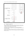
4.6
Turning the system “On” .......................................................................................... 15
4.7
ALDM Software Configuration (“fbas.ini”): .......................................................... 16
To modify the ALDM configuration file: ................................................................... 16
ALDM Software Configuration variables:.......................................................................................... 18
Default contents of the “fbas.ini” configuration file ........................................................................... 20
5
4.8
EIA RS-232C Communication Port ......................................................................... 21
4.9
Integration with Quizix PumpWorks™................................................................... 25
The ALDM Console ................................................................................................. 27
5.1
Front Panel Description............................................................................................. 27
“Power ON” Indicator......................................................................................................................... 27
“CPU” Bore-A and “CPU” Bore-B (Three Phase Separator) ............................................................. 27
“Volume Reset Bore A” and “Volume Reset Bore B” (Three Phase Separator) ................................ 27
“Host Data”, “Bore A Data” and “Bore B Data” (Three Phase Separator)......................................... 27
5.2
Rear Panel Description .............................................................................................. 27
Power Input......................................................................................................................................... 28
Transducer Bore A.............................................................................................................................. 28
Transducer Bore B (Three Phase Separator)....................................................................................... 28
Diagnostic A / Diagnostic B (Three Phase Separator) ........................................................................ 28
Video A / Video B (Three Phase Separator) ....................................................................................... 28
Serial Port ........................................................................................................................................... 28
Keyboard A / Keyboard B (Three Phase Separator) ........................................................................... 28
Mouse A / Mouse B (Three Phase Separator)..................................................................................... 28
CPU Reset A / CPU Reset B (Three Phase Separator) ....................................................................... 28
6
Principle of Operation ............................................................................................. 29
- 2/42 -
Acoustic Level Detection Module (ALDM) User's Manual
6.1
Three Phase Separators - The Data Link Status Panel .......................................... 32
6.2
Description of Electronic Functions ......................................................................... 36
6.3
Error Messages........................................................................................................... 38
7
Ultrasonic Transducer ............................................................................................. 40
8
Serial Commands ..................................................................................................... 41
Two-Phase and Three-Phase Commands:........................................................................................... 41
? or 0x05......................................................................................................................................... 41
r or R .............................................................................................................................................. 41
Additional Three-Phase Separator Commands: .................................................................................. 41
c or C.............................................................................................................................................. 41
v or V ............................................................................................................................................. 41
- 3/42 -
Acoustic Level Detection Module (ALDM) User's Manual
2
Table of Figures
Figure 1 Removing the fuse holder..................................................................................... 8
Figure 2 North American fuse arrangement ....................................................................... 9
Figure 3 European fuse arrangement .................................................................................. 9
Figure 4 Electronics console front view (three phase separator version) ......................... 10
Figure 5 Electronics console rear view (three phase separator version)........................... 10
Figure 6 KVM connections............................................................................................... 10
Figure 7 Typical two-phase separator vessel .................................................................... 11
Figure 8 A hybrid three-phase separator vessel................................................................ 12
Figure 9 Ultrasonic transducer assembly.......................................................................... 15
Figure 10 Two-Phase Separator Serial Protocol Example................................................ 23
Figure 11 Three-Phase Separator Serial Protocol Example.............................................. 24
Figure 12 PumpWorks separator communications step #1............................................... 25
Figure 13 PumpWorks separator communications step #2............................................... 26
Figure 14 View separator data .......................................................................................... 26
Figure 15 ALDM Electronics Console Front Panel (Three Phase Separator) .................. 27
Figure 16 ALDM Electronics Console Rear Panel (3 Phase)........................................... 27
Figure 17 A typical two-phase separator vessel. .............................................................. 29
Figure 18 A hybrid three-phase separator......................................................................... 30
Figure 19 Staggered three-phase separator ....................................................................... 31
Figure 20 Data Link front panel........................................................................................ 32
Figure 21 Data Link serial protocol .................................................................................. 33
Figure 22 A (conceptual) three-phase separator that requires a VAC constant................ 34
Figure 23 ALDM Video Screen........................................................................................ 37
- 4/42 -
Acoustic Level Detection Module (ALDM) User's Manual
3
General Information
3.1
Introduction
The NER Acoustic Level Detection Module (ALDM), part number : NERAS-2000ELEC / NERAS-3000-ELEC, is a precision ultrasonic level monitor. The ALDM
measures the level of two fluids in a gravity-based 2-phase high-pressure separator. It
provides output signals (serial ASCII characters) proportional to either absolute level or
relative to a user-selectable set-point.
This manual contains installation and operating instructions for the ALDM used in both
2-Phase and 3-Phase separator configurations. Instrument specifications and procedures
for verifying proper operation are included
Block diagrams, theory of operation, and separator disassembling / assembling
information are provided for use in maintaining the instrument, as well as a spare parts
list.
3.2
Specifications
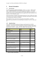
This section of the manual contains performance specifications for the ALDM
instrument. It also lists the accessories supplied, and includes instrument and manual
identification information. Table 1 Transducer Specifications and Table 2 Electronics
Specifications, provides a complete list of the ALDM critical specifications.
Parameter
Value
Units
Working Pressure
1-700
Bar
Temperature
15-150
Celsius
Fluids
Reservoir Oil and Brine
Maximum change of water volume
999
ml
Maximum change of oil volume
999
ml
Typical volume resolution (25.4
mm bores, water-paraffin)
0.08
ml
Hysteresis*
0.3 ml
ml
Transducer construction
PZT-5A, plastics, viton and
epoxy
Plastics, viton o-ring
1.5
MHz
Typical A2D Sample Period (User
adjustable 2.5e-7 to 2.5e-8);
1e-7
Second
Maximum trace length
125,000
Samples
Required Vertical Positioning
± 2.5 deg. from true vertical
Transducer wetted parts
Transducer resonance frequency
Table 1 Transducer Specifications
- 5/42 -
Acoustic Level Detection Module (ALDM) User's Manual
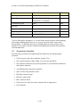
Property
Value
Units
Warm-up time
30
minutes
PC interface
EIA RS-232C, ASCII, Quizix
PumpWorks™ compatible
Transmission speed
9600
Data bits
8
Parity
No parity
Stop bit(s)
1 stop bit (Hi)
Mains supply
100/120, 220/240 Auto-switching
Baud
VAC
Table 2 Electronics Specifications
* Due to fluid surface mechanics, i.e. reversal of the meniscus surface when changing
from rising to falling liquid levels or vice versa, a hysteresis effect occurs in the
measurements. To minimize this, the user should prepare the inner surfaces of the
separator in accordance with the cleaning and preparation instructions from separator
vessel manufacturer.
3.3
Accessories Supplied
The following accessories are supplied with the ALDM for two and three phase
separators:
•
US style power cords, three conductor, length: 2.5 m.
•
One coaxial transducer cable, length: 6 m. per active transducer.
•
One ultrasonic transducer (two phase separators) or two ultrasonic transducers
(three phase separator).
•
An additional spare ultrasonic transducer.
•
Spare Viton O-ring transducer seals.
•
Hastelloy reference target.
•
Reference target stand.
•
BNC connector block.
•
Serial cross-over cable (for a host computer link or diagnostics)
•
User's Manual.
- 6/42 -
Acoustic Level Detection Module (ALDM) User's Manual
4
Installation, Interfacing and Safety
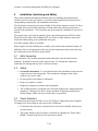
This section contains information and instructions for installing and interfacing the
ALDM, as well as safety precautions. It includes initial inspection procedures, power
and grounding requirements, and installation instructions.
The electronics console must be located within 20 feet of the separator vessels (20 feet is
the length of the special high-temperature coaxial cables that connect the electronics
console to the separators). The electronics may be mounted in a standard 19 inch rack if
desired.
The console may come with an optional 2-port video-keyboard-mouse (KVM) switch.
The KVM switch allows the embedded CPU’s to utilize a single monitor, mouse and
keyboard without taking up any additional desk space.
All of the required cables are included.
Please inspect all of the ALDM parts carefully, and read all of the manuals included. In
addition to this set of instructions, there may be other manuals provided which describe
the components of the ALDM in greater detail.
4.1
Initial Inspection
This instrument was carefully inspected both mechanically and electrically before
shipment. It should be in perfect order upon receipt. To confirm this, inspect the
instrument for damage that may have occurred in transit.
4.2
Safety
•
Ground the instrument. To avoid shock hazard, the instrument chassis must be
connected to an electrical ground. The instrument is equipped with a threeconductor AC power cable.
•
Do not operate in an explosive atmosphere.
•
Keep away from live circuits.
•
Dangerous voltages are present in this instrument.
•
The ALDM separator is designed to be used with high-pressure, high-temperature
equipment. Damage to the device under operation or improper assembly may
lead to leakage, which can cause serious injury to personnel.
4.3
Power Selection:
The instrument can be operated from 110 or 220 Volts AC single-phase power supplies,
according to the fuse setting on rear panel of the ALDM unit.
•
Confirm that the electronics console has the correct fuses installed for the power
at your location.
•
The proper fusing for the electronics is selected by adjusting the “Power Entry
Module” located on the back of the electronics console.
- 7/42 -
Acoustic Level Detection Module (ALDM) User's Manual
•
Be certain to use 250V fuses in all locations.
Fuse Installation Instructions:
1.
Remove power cord.
2.
Pry door open at socket.
3.
Lift and swing door into socket.
4.
Lift fuse holder out of housing.
5.
Install one (1) AG fuse or two (2) metric fuses*.
6.
Replace fuse holder into housing.
7.
Swing and snap door back in place.
*Install fuses on one side only. Do not install both AG and metric fuses at the same time.
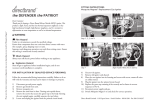
Figure 1 Removing the fuse holder
- 8/42 -
Acoustic Level Detection Module (ALDM) User's Manual
Figure 2 North American fuse arrangement
Figure 3 European fuse arrangement
Fuse Selection Chart
Location
North America
Qty
1
Fuse (Maximum Rating)
3 Amp / 250V 3AG, ¼ x 1¼ Time Delay
Europe
2
3 Amp / 250V, 5mm x 20mm, Time Delay
- 9/42 -
Acoustic Level Detection Module (ALDM) User's Manual
4.4
Basic Cable Connections:
First, familiarize yourself with the ALDM components and some typical separator
pressure vessels:
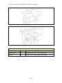
Figure 4 Electronics console front view (three phase separator version)
Figure 5 Electronics console rear view (three phase separator version)
Figure 6 KVM connections
- 10/42 -
Acoustic Level Detection Module (ALDM) User's Manual
Figure 7 Typical two-phase separator vessel
- 11/42 -
Acoustic Level Detection Module (ALDM) User's Manual
Figure 8 A hybrid three-phase separator vessel
- 12/42 -
Acoustic Level Detection Module (ALDM) User's Manual
Cables supplied with this system:
•
[A] (2) VGA Video cables for use with the KVM switch
•
[B] (2) PS2 Keyboard cables for use with the KVM switch
•
[C] (2) PS2 Mouse cables (not required for operation) for use with the KVM
switch.
•
[D] (2) Teflon coaxial “separator” signal cables.
•
[E] (1) Electronics console power cord.
•
[F] (1) 9-pin, serial cross-over cable.
Connections required for standalone operation:
Electronics Console
To
Use Cable Type
Video A
KVM 1st VGA Port
[A] VGA video cable
Video B
KVM 2nd VGA Port
[A] VGA video cable
Transducer Bore A
“Separator 1” Ultrasonic
Transducer (Pressure Vessel)
[D] Teflon coaxial cable
Transducer Bore B
“Separator 2” Ultrasonic
Transducer (Pressure Vessel)
[D] Teflon coaxial cable
AC Power Source
Electronics Console
[E] Power cord
KVM Switch
Console VGA
Use Cable Type
To Video Monitor VGA
Video Monitor Cable
Connections required for configuration and diagnostics only:
Electronics Console
Keyboard A
To
Use Cable Type
st
[B] PS2 Keyboard Cable
nd
KVM 1 Keyboard Port
Keyboard B
KVM 2 Keyboard Port
[B] PS2 Keyboard Cable
Diagnostics A or B
Host Computer
[F] Cross-Over Cable
KVM Switch
Console Keyboard
Use Cable Type
To Keyboard
Attached Keyboard Cable
Connections required for remote data transfer & control:
Electronics Console
To
Use Cable Type
Serial Port
Host Computer (or Quizix®
Computer)
[F] Cross-Over Cable
- 13/42 -
Acoustic Level Detection Module (ALDM) User's Manual
4.5
Transducer Assembly
The ALDM comes supplied with a specially designed ultrasonic transducer assembly.
Transducer Assembly Components – 2 Phase Separator Systems
Qty
1
Description
Ultrasonic Reference Target
1
Reference Target Stand
2
Ultrasonic Transducer Assembly (1 Spare)
1pkg
#119 Viton O-rings
1
BNC Connector Block
Transducer Assembly Components – 3 Phase Separator Systems
Qty
2
Description
Ultrasonic Reference Target
2
Reference Target Stand
3
Ultrasonic Transducer Assembly (1 Spare)
1pkg
#119 Viton O-rings
2
BNC Connector Block
The Ultrasonic Transducer Assembly may arrive wrapped in black plastic tape. The tape
ensures that the assembly remains intact during shipment. The tape also provides
minimal strain relief for the signal wires. The signal wires are very fragile, and can be
easily broken. Remove the shipping tape before inserting the assembly into an
appropriately sized holder. Be careful handling the transducer when the shipping tape is
removed.
The transducer assembly will require the attachment of the two signal wires for operation.
These wires must be soldered with the supplied high-temperature solder, or a similar
solder rated for your operating temperatures.
The black wire from the transducer should be connected to the shield connection of the
BNC connector. The other wire may vary in color (red, white, etc.), and should be
connected to the BNC center pin.
- 14/42 -
Acoustic Level Detection Module (ALDM) User's Manual
Figure 9 Ultrasonic transducer assembly
4.6
Turning the system “On”
The main system power switch is located on the back of the electronics console. Upon
activation, the separator system starts the boot procedure. Progress, as well as any error
or diagnostic messages will appear on the video output.
For three-phase systems, the boot procedures (as well as all other functions) are
independent for both Bore A and Bore B. You may need to change the KVM selection to
view the desired output.
Eventually a graphical display will appear that shows the current output of either Bore A
or Bore B. You can switch the view of the current output to another bore by changing the
KVM switch setting.
- 15/42 -
Acoustic Level Detection Module (ALDM) User's Manual
4.7
ALDM Software Configuration (“fbas.ini”):
The various software settings used by the ALDM computer are held in a configuration
file titled fbas.ini.
If the hardware setup is altered, it may become necessary to adjust the settings in the
fbas.ini file. This can be accomplished using the following procedure. Keep in mind that
you can change the configuration settings for only one bore at a time. For three phase
separators, any changes that are applied to “Bore A” may also have to be applied to
“Bore B”.
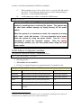
To modify the ALDM configuration file:
1.
2.
3.
4.
Start with the ALDM electronics turned off.
Make sure the monitor and keyboard are plugged into the ALDM
electronics console or KVM switch.
Turn the power to the ALDM electronics console to “On”.
When a blue screen with the text “Press any key to enter the menu”
appears, quickly press any key on the keyboard. If you do not press a key
within time, the ALDM will boot normally. If this happens, power cycle
the electronics console, or press the “CPU Reset” button on the back of the
ALDM electronics to try again.
- 16/42 -
Acoustic Level Detection Module (ALDM) User's Manual
5.
6.
By default, the ‘embedded linux’ entry is selected. Using the arrow keys,
select ‘maintenance’ option, then press enter.
The ALDM will now boot into maintenance mode. Eventually a login
prompt will appear. Type ‘root’ (without quotes), and press enter. For the
password type ‘root*” (without quotes), as shown below in red.
NER embedded linux development and maintenance system
Fedora Core 2 2.6.5-1.358 on an i386
Use field root login:
Midge login: root
Password: root*
7.
Now type “./sepcfg” to start the configuration editor:
NER embedded linux development and maintenance system
Fedora Core 2 2.6.5-1.358 on an i386
Use field root login:
Midge login: root
Password: root*
Last login: Saturday August 18 on tty1
NER embedded linux development and maintenance system
Midge: ./sepcfg
8.
The configuration editor, “jed”, appears. Using the arrow keys, edit the
configuration file as necessary (see the next section).
- 17/42 -
Acoustic Level Detection Module (ALDM) User's Manual
9.
10.
When complete, press <Ctrl>-x, then <Ctrl>-c to save the file and exit the
text editor. If you made any changes that you wish to make permanent,
then press ‘y’ at the confirmation prompt.
At the prompt, type ‘reboot’ to restart the ALDM system.
Midge: reboot
Please note: When the ALDM is running in ‘Normal’ mode, the
system is operating from a read-only file system. The system may
be shut down without damage by simply turning off the power
switch.
When the system is in ‘maintenance mode’, the computer is running
with “read – write’ disk access. It is very important not to power
down the system by using the power switch. Use the ‘reboot’
command to restart the separator system.
After the system
successfully restarts, you can then power–down using the main
power switch.
ALDM Software Configuration variables:
The syntax for values in the “fbas.ini” configuration file is:
set <variablename> <value>
•
One entry per line.
•
All variables are case sensitive!
•
If 'value' is a string with spaces, use quotation marks (") around the value.
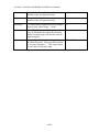
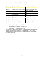
Variables in "fbas.ini" that may be modified:
Variable
Function
Typical Value
borediam
Bore diameter in inches.(Measurement Bore)
Actual Bore diameter1
borediam2
Bore diameter in inches. (Separation Bore)
Actual Bore diameter1
cmax
Max allowable 'Heavy Fluid' speed (KM/s)
2.0
cmin
Min allowable 'Heavy Fluid' speed (KM/s)
0.8
h2htime
Head-to-head (transducer) time in 10^(-6)
seconds
14.88
1
Separator vessels with unexpected geometries can be accommodated by adjusting the bore diameters as
needed to allow the ALDM to report correct volume measurements.
- 18/42 -
Acoustic Level Detection Module (ALDM) User's Manual
heavyname
String label for heavy fluid (normal text
characters only, no square brackets)
Brine
lightname
String label for light fluid (normal text
characters only, no square brackets).
Oil
maxrange
... in inches (Bore length minus safety margin).
Typical value: (Bore length – 1 inch)
14
minrange
... in inches (Closest possible acquisition - be
wary of making this too small, the ultrasonic
shadow from the target will interfere with the
acquired signal).
4
titlestring
User configurable string that is displayed on
the NERAS monitor. If not specified, defaults
to “Acoustic Separator - ”. This string cannot
be more than 34 characters long.
NER ALDM
- 19/42 -
Acoustic Level Detection Module (ALDM) User's Manual
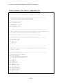
Default contents of the “fbas.ini” configuration file
#-----------------------------------------------------------#
# stuff you might (BUT NEED NOT NECESSARILY) change
#
#-----------------------------------------------------------# text labels: MUST be in double qoutes
set titlestring "Acoustic Level Detector"
set heavyname "brine"
set lightname "oil"
# bore sizes in inches
set borediam 1.00
set borediam2 1.00
#-----------------------------------------------------------#
# stuff that may need field changes but that's really tricky and
# can break the whole system in hard-to-detect ways.
#
# CONSULT THE VENDOR before you change any of these.
#
#-----------------------------------------------------------set maxrange 14.00
set minrange 5.00
set cmin 0.8
set cmax 2.0
set dt 1e-7
#-----------------------------------------------------------#
# STUFF YOU SHOULD NOT NEED TO CHANGE EVER EVER EVER without a
# special license.
#
#-----------------------------------------------------------set serialnumber 1027
set default_boxcol hotpink
set bgcol "azure"
set plotfont hersheyserif-bold
set resultfont courier-bold
set usel2 0
set useenv 1
set agamma 0.01
set etasim 0.1
set amplpwr 2.0
set h2htime 14.88
set refrange 2.00
set refreflead 2e-6
set intreflead 2e-6
set xpixels 1024
set ypixels 768
set bitsperplane 16
- 20/42 -
Acoustic Level Detection Module (ALDM) User's Manual
4.8
EIA RS-232C Communication Port
Communication is performed via standard asynchronous RS-232C interface operating at
9600 baud, 8 bits, 1 stop bit, no parity, no flow control. Key parameters for the RS232C link are given in Table 4 and in section 8, Serial Commands. The pin-out of the 9pin RS-232C socket is as given in Table 3 RS-232C Connector Pinout.
Pin Number
Function
1
2
3
no connection
This pin outputs data to the PC
Data from the PC is to be applied to this pin
4
no connection
5
Ground
6-9
no connection
Table 3 RS-232C Connector Pinout
Communication consists of:
1.
Data request, which is always results in a transfer of measured values and
error codes to the PC.
2.
Reset of relative volume reading.
A data request cycle is initiated when the code "ENQ" (ASCII 0x05) or the ASCII
character “?”, is received followed by a carriage return "CR" (ASCII 0x0D). ALDM
responds by sequencing through a measurement cycle and returning the newly measured
data, together with an error message. The data string is formatted as shown in Table 4
RS-232 Data Format.
Reset of relative volume reading is carried out on receipt of "R": or "r" (ASCII 52h or
72h) followed by a "CR". ALDM responds by resetting both relative volume readings to
zero. No confirmation code is returned.
- 21/42 -
Acoustic Level Detection Module (ALDM) User's Manual
Serial Output Two-Phase ALDM Output
Three-Phase ALDM Output
Bytes 1-8
Error Codes
Error Codes
Bytes 9-13
Absolute Volume of the Light Fluid Absolute Volume (Upper Phase
Bore B), Light Fluid
Bytes 14-19
Relative Volume of the Light Fluid Relative Volume of the Light
Fluid
Bytes 20-23
Heavy fluid velocity
Fluid Velocity (Bore B), Middle
(meters/second)
Fluid
Byte 24-28
Absolute Volume of the Heavy
Absolute Volume of the Heavy
Fluid
Fluid (Lower Phase Bore A)
Byte 29-34
Relative Volume of the Heavy
Relative Volume of the Heavy
Fluid
Fluid
Byte 35-38
Heavy fluid velocity
Fluid Velocity (Bore A), Heavy
(meters/second)
Fluid
Byte 39
Carriage Return (0Dh)
Carriage Return (0Dh)
Table 4 RS-232 Data Format
•
Absolute volume = 5 characters. NNN.NN in ml
•
Relative volume = 6 characters. ±NNN.NN in ml
•
Sound velocity = 4 characters NNNN in m/s.
All characters are numeric (ASCII 30h to 39h). Leading zeros are used when number is
less than full scale. Relative volumes use "+" (ASCII 2Bh) and "-" (ASCII 2Dh) to
indicate whether the volumes are higher or lower than when last reset. Decimal points
are implied and not sent.
- 22/42 -
Acoustic Level Detection Module (ALDM) User's Manual
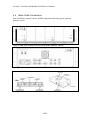
A response to a status query is listed blow for both two and three phase systems. Please
note that the list may include commands that are not compatible with earlier versions of
the ALDM, or other manufacturer’s control-systems.
Figure 10 Two-Phase Separator Serial Protocol Example
- 23/42 -
Acoustic Level Detection Module (ALDM) User's Manual
Figure 11 Three-Phase Separator Serial Protocol Example
- 24/42 -
Acoustic Level Detection Module (ALDM) User's Manual
4.9
Integration with Quizix PumpWorks™
The ALDM for two and three-phase separators from New England Research, Inc. are
fully compatible with the current “PumpWorks™” software release from Quizix (V 5.35
– B5). Quizix supplies pumps that are commonly used in separator systems. Please note
that New England Research, Inc. makes every effort to ensure that our Acoustic Level
Detection Modules will function seamlessly with PumpWorks™. However, we cannot
guarantee this functionality for different versions of PumpWorks™ or hardware changes
that are beyond our control.
Quizix Incorporated
4616 Roseville Road, Suite 108
North Highlands, CA 95660
www.quizix.com
*Quizix product and company names (Quizix, PumpWorks, …) are trademarks or
trade names of Quizix Incorporated.
The ALDM console may be detected automatically2 upon starting PumpWorks™. If this
is not the case, you can manually configure PumpWorks™ to recognize and control the
two or three phase separator ALDM as shown below:
1.
Select “Communications” ⇒ “Separator Communications” ⇒ “Separator
3” (select “Separator 3” even if you are using a two phase separator).
Figure 12 PumpWorks separator communications step #1
2
PumpWorks sends out a query to available hardware. In some case, this query can leave unwanted
characters on the communication bus. These characters may cause a communications “timeout” when you
try to initialize the separator setup. Simply retry the separator setup until communications are established
with the ALDM.
- 25/42 -
Acoustic Level Detection Module (ALDM) User's Manual
2.
Apply the settings shown below. The “Com Port” setting, Com8, may be
different for your system. Select “Enable Separator” when finished.
Figure 13 PumpWorks separator communications step #2
3.
You can view the current separator data by selecting “Other” ⇒
“Separator Data” from the main menu.
Figure 14 View separator data
Please see the PumpWorks™ documentation for more information on the operation and
setup of the PumpWorks™ software.
- 26/42 -
Acoustic Level Detection Module (ALDM) User's Manual
5
The ALDM Console
This section provides general operating information and functional identification of all
controls and connectors on the ALDM unit.
5.1
Front Panel Description
Figure 15 ALDM Electronics Console Front Panel (Three Phase Separator)
“Power ON” Indicator
This green indicator signifies that the Electronics Console’s power switch is in the “On”
position and the unit is receiving AC power.
“CPU” Bore-A and “CPU” Bore-B (Three Phase Separator)
This red indicator flashes when the embedded CPU is active. A program or hardware
error is indicated by this LED remaining constantly on or off.
“Volume Reset Bore A” and “Volume Reset Bore B” (Three Phase
Separator)
When this red switch is pushed, the relative reading of liquid level is set to zero.
“Host Data”, “Bore A Data” and “Bore B Data” (Three Phase
Separator)
These panel mounted LED’s indicate serial communication activity with an external host.
5.2
Rear Panel Description
Figure 16 ALDM Electronics Console Rear Panel (3 Phase)
- 27/42 -
Acoustic Level Detection Module (ALDM) User's Manual
Power Input
Main AC supply connection and fuse location. Connect 110 – 240VAC at 50/60 Hz.
Maximum current is 4 amps.
Transducer Bore A
This is the ultrasonic transducer connection for Bore A. Connect the transducer using the
supplied high-temperature coaxial cable.
Transducer Bore B (Three Phase Separator)
This is the ultrasonic transducer connection for Bore B. Connect the transducer using the
supplied high-temperature coaxial cable.
Diagnostic A / Diagnostic B (Three Phase Separator)
These are the diagnostic serial ports for the Bore A and B CPU’s. Protocol settings are:
9600 baud, 8-n-1. No connection is required for normal use.
Video A / Video B (Three Phase Separator)
Video output for each bore. These outputs may be connected to an external KVM switch
to allow the use of one video monitor.
Serial Port
Data acquisition and control port. This port is commonly connected to Quizix® control
systems. It may also be connected to any computer using a serial terminal program. See
section 4.8, EIA RS-232C Communication Port for configuration information and
available commands.
Keyboard A / Keyboard B (Three Phase Separator)
Connect an external keyboard adjust the configuration settings. These ports may be
connected to an external KVM switch to allow the use of only one keyboard.
Mouse A / Mouse B (Three Phase Separator)
These connectors currently have no function.
CPU Reset A / CPU Reset B (Three Phase Separator)
When pushed, these buttons reset the corresponding embedded CPU. Effectively restarts
the system without disconnection the power. Each bore ha an independent CPU Reset
button.
- 28/42 -
Acoustic Level Detection Module (ALDM) User's Manual
6
Principle of Operation
This section contains functional descriptions keyed to overall, simplified mechanical
drawings or block diagrams of electronic circuits.
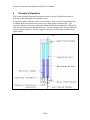
A typical two-phase separator vessel is shown below. Notice how the measurement bore
is isolated from the separation bore, preserving a high quality liquid interface. The
ultrasonic transducer, reference target and electrical connections supplied by NER can be
seen near the bottom of the measurement bore. The bore diameters are user specified and
may be unequal diameters. The bore length is also user specified and is limited only by
signal quality.
Figure 17 A typical two-phase separator vessel.
- 29/42 -
Acoustic Level Detection Module (ALDM) User's Manual
A hybrid three-phase separator vessel is shown below. In this configuration, two twophase systems are connected together. This configuration enables the measurement of
three different volumes while also recording the wave velocity in the two heaviest fluids.
The light fluid may be a gas.
The ultrasonic transducer, reference target and electrical connections supplied by NER
can be seen near the bottom of each measurement bore.
Figure 18 A hybrid three-phase separator
- 30/42 -
Acoustic Level Detection Module (ALDM) User's Manual
A specific purpose, staggered three-phase separator vessel is shown below. In this
configuration, the separation bore is in the center and the measurement bores are isolated
on either side, still preserving the high quality liquid interfaces.
This setup preserves the same resolution as the hybrid separator, however material and
machining cost is reduced. The three-phase separator communication interface allows
the implementation of a volume offset to the measurements. This coupled with user
specified bore diameters, allows the ALDM to be configured for nearly any conceivable
hardware setup. See section 4.7, “ALDM Software Configuration (“fbas.ini”):” for more
details.
Figure 19 Staggered three-phase separator
- 31/42 -
Acoustic Level Detection Module (ALDM) User's Manual
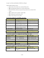
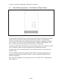
6.1
Three Phase Separators - The Data Link Status Panel
Figure 20 Data Link front panel
The Data Link feature allows the two data streams from each bore (A & B) to be merged
and sent out the serial port on the back of the electronics console. The “Host Data”
indicator will illuminate when a command from a host computer is pending and waiting
for a response. The “Bore A Data” and “Bore B Data” indicators will illuminate when
there is a measurement being acquired from the respective subsystems.
An indicator that remains lit informs the user that communication with a subsystem could
not be established. Please check the condition of the communications cable.
The Data Link card is connected directly to the serial port connector on the back of the
ALDM console.
You may configure and test the operation of the data link by using a general purpose
serial terminal program (like “HyperTerminal”, which is installed by default on most
Windows computers).
The serial port configuration is described in section 4.8, EIA RS-232C Communication
Port on page 20.
- 32/42 -
Acoustic Level Detection Module (ALDM) User's Manual
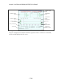
Figure 21 Data Link serial protocol
- 33/42 -
Acoustic Level Detection Module (ALDM) User's Manual
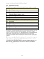
The “Volume Adjustment Constant” (see Figure 22 A (conceptual) three-phase separator
) is a constant value in [ml] that is subtracted from the Heavy Fluid volume. This is
required for a staggered 3-Phase vessel setup where the separation and measurement
bores for the heavy fluid are not the same length.
The Volume Adjustment Constant (VAC) can be calculated by:
VAC [ml ] =
HeightDifference[mm]× π × BoreRadius[mm]
1000
2
Figure 22 A (conceptual) three-phase separator that requires a VAC constant.
The default value is 64.61[ml]. This value can be set (and is reported) as 6461 by the
Data Link card (the last two digits are always assumed to be right of the decimal point).
- 34/42 -
Acoustic Level Detection Module (ALDM) User's Manual
For example, if a new VAC value is determined to be 50.33 [ml], you would send the
command ‘c5033’ to the Data Link card.
All other commands not listed in the graphic above are forwarded to the individual bores,
and each response is forwarded back. The response from Bore A is preceded by an ‘A’
and the response from Bore B preceded by a ‘B’.
The “Host Data” LED illuminates Data Link card receives a command from a host. The
LED is turned off when the entire transaction is completed. The “Bore A Data” LED
blinks when the processor is waiting for a response from Bore A, and the “Bore B LED”
blinks when the processor is waiting for a response from Bore B.
A problem with a bore's data stream can result in a non-responsive Data Link card, and
one of the Data LED’s remaining continuously lit.
- 35/42 -
Acoustic Level Detection Module (ALDM) User's Manual
6.2
Description of Electronic Functions
ALDM measurements are carried out under the control of one or more embedded
computers in the electronics console.
The acquisition process starts when the control system initiates an ultrasonic pulse
transmitted from the transducer. The ultrasonic energy is transmitted into the fluid in the
vessel. This energy wave first encounters the reference target that is placed a known
distance away from the transducer face. Some of the transmitted energy is then reflected
back to the ultrasonic transducer. This reflection from the target is then received by an
ultrasonic amplifier and routed to the data acquisition subsystem and stored in memory.
However, most of the ultrasonic energy passes by the reference target and continues past.
When a fluid interface is reached, again some of the energy is reflected back toward the
ultrasonic transducer. This reflected signal is also acquired and saved to be processed.
The embedded computer then processes this information, automatically matching the
acquired waveforms with a stored library of reference waveforms. From this match an
accurate and stable “pick time” can be calculated.
The system automatically calibrates out any pressure and temperature effects on the fluid
by using the information from the reference target waveform. The speed of the heavy
fluid is then calculated. Next the arrival of the fluid interface is processed, and along
with the stored vessel geometry information, the fluid volumes can be calculated.
This information is then displayed on the video output, and is made available to the
digital serial link, if present.
This entire process is automatic and does not require any user intervention or threshold
adjustments. In addition, the raw waveforms and a plot of the match quality is displayed
on the video output. This makes the NER ALDM one of the easiest and most reliable
ultrasonic level measuring systems available.
- 36/42 -
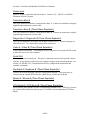
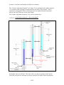
Acoustic Level Detection Module (ALDM) User's Manual
Amplitude Quality
Meter
Reference Target
Zoom
Fluid Interface
Zoom
Fluid Interface
Match
Reference Target
Match
Fluid Interface
Waveform
Reference Target
Waveform
Heavy Fluid Speed
Time
(microseconds)
Error Code
Absolute and
Relative Volumes
Figure 23 ALDM Video Screen
Once the computer has located the interface signal, the relative volumes are calculated,
and the results displayed on the screen.
- 37/42 -
Acoustic Level Detection Module (ALDM) User's Manual
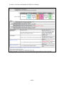
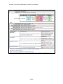
6.3
Error Messages
If an error information code is present in the data packet, then all other data in the packet
are to be regarded as invalid. If valid data has been acquired, then the data packet should
start with "STATUS OK" message, and a “Status: OK” indication should appear on the
video output:
Table 5 is a complete list of the error codes and the necessary corrective actions for TwoPhase Separators.
DISPLAY TEXT
RS-232 CODE
Cause/action
STATUS OK
STATS OK
System is operating normally.
ERR1, SOUND VEL
COUNT LOW!
ERROR1
Oil-water interface is too close to the
transducer. Add water. Noise level
exceeds threshold when the detector is
enabled, causing erroneous reference
and echo detection.
ERR2, SOUND VEL
COUNT HIGH!
ERROR2
Too weak reference signal. Reference
target is out of adjustment.
ERR3, WAT-OIL INT
COUNT LOW!
ERROR3
The oil-water interface is too low. Add
water.
ERR4,WAT-OIL INT
COUNT HIGH!
ERROR4
The oil-water interface is above upper
limit. Drain water.
Table 5 Two-Phase Separator Error Codes
In addition to the errors codes listed above, Table 6 is a list of the additional error codes
and the necessary corrective actions for Three-Phase Separators.
DISPLAY TEXT
RS-232 CODE
Cause/action
STATUS OK
ERROR0
This bore is operating normally.
ERROR8
ERROR8
Communication timeout. There is a
problem with the embedded
communication bus. Contact NER.
ERROR9
ERROR9
Garbled data received. Try removing
any sources of electrical interference
from the proximity of the ALDM
system. Contact NER.
Table 6 Three-Phase Separator Error Codes
- 38/42 -
Acoustic Level Detection Module (ALDM) User's Manual
The Error Codes for a three-phase system are concatenated into a single result like so:
Error<Bore A Error Code><Bore B Error Code><Recovered Data>
•
For example, a result like:
“Error02 26839+21278167411129-212781674”
Indicates that Bore A is operating correctly and Bore B has encountered an “ERROR2”
as described in the table above. The data included in this response may not be reliable.
•
Similarly the result below:
“Error20 26839+21278167411129-212781674”
Indicates that Bore B is operating correctly and Bore A has encountered an “ERROR2”
as described in the table above. The data included in this response may not be reliable.
- 39/42 -
Acoustic Level Detection Module (ALDM) User's Manual
7
Ultrasonic Transducer
The ultrasonic transducer should not require any maintenance.
It is suggested that the unit be returned to New England Research, Inc. if the ultrasonic
transducer needs servicing.
It may be necessary to cut and replace the electrical connections to the coaxial connector
in order to service this component. Repair of electrical connections on the ultrasonic
transducer requires the use of high-temperature solder.
- 40/42 -
Acoustic Level Detection Module (ALDM) User's Manual
8
Serial Commands
The ALDM listens for commands on /dev/ttyS0, configured for 9600 Baud, 8 bits, 1 stop
bit, no parity, and no flow control. It responds to certain command characters, when
followed by a new-line or carriage return, as detailed below. Each response is terminated
by a new-line.
Two-Phase and Three-Phase Commands:
? or 0x05
The ALDM will return the standard status information and data.
See Figure 10 Two-Phase Separator Serial Protocol Example or Figure 11 ThreePhase Separator Serial Protocol Example.
r or R
Send a reset command to the ALDM. This will reset the relative volume counters.
Additional Three-Phase Separator Commands:
c or C
Set or report the internal “volume adjustment constant” calibration.
See Figure 11 Three-Phase Separator Serial Protocol Example.
v or V
Return the version number of the data-link card firmware.
- 41/42 -
Acoustic Level Detection Module (ALDM) User's Manual
End of document.
- 42/42 -