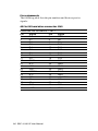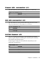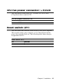
1
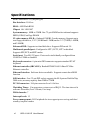
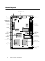
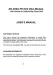
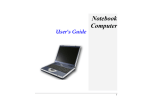
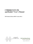
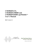
SBC-411/411E
Half-size 486 All-in-One CPU Card
with Cache
FCC STATEMENT
THIS DEVICE COMPLIES WITH PART 15 FCC RULES. OPERATION IS SUBJECT TO THE FOLLOWING TWO CONDITIONS:
(1) THIS DEVICE MAY NOT CAUSE HARMFUL INTERFERENCE. (2) THIS DEVICE MUST ACCEPT ANY INTERFERENCE
RECEIVED INCLUDING INTERFERENCE THAT MAY CAUSE
UNDESIRED OPERATION.
THIS EQUIPMENT HAS BEEN TESTED AND FOUND TO
COMPLY WITH THE LIMITS FOR A CLASS "A" DIGITAL
DEVICE, PURSUANT TO PART 15 OF THE FCC RULES.
THESE LIMITS ARE DESIGNED TO PROVIDE REASONABLE PROTECTION AGAINTST HARMFUL INTERFERENCE WHEN THE EQUIPMENT IS OPERATED IN A
COMMERCIAL ENVIRONMENT. THIS EQUIPMENT GENERATES, USES, AND CAN RADIATE RADIO FREQENCY
ENERGY AND , IF NOT INSTATLLED AND USED IN ACCORDANCE WITH THE INSTRUCTION MANUAL, MAY CAUSE
HARMFUL INTERFERENCE TO RADIO COMMUNICATIONS. OPERATION OF THIS EQUIPMENT IN A RESIDENTIAL AREA IS LIKELY TO CAUSE HARMFUL INTERFERENCE IN WHICH CASE THE USER WILL BE REQUIRED
TO CORRECT THE INTERFERENCE AT HIS OWN EXPENSE.
Copyright Notice
This document is copyrighted, 1998, by AAEON Technology Inc.
All rights are reserved. AAEON Technology Inc. reserves the right
to make improvements to the products described in this manual at
any time without notice.
No part of this manual may be reproduced, copied, translated, or
transmitted in any form or by any means without the prior written
permission of AAEON Technology Inc. Information provided in
this manual is intended to be accurate and reliable. However,
AAEON Technology Inc. assumes no responsibility for its use, nor
for any infringements upon the rights of third parties which may
result from its use.
Acknowledgements
ALI is a trademark of Acer Laboratories, Inc.
AMD is a trademark of Advanced Micro Devices, Inc.
AMI is a trademark of American Megatrends, Inc.
AutoCAD and AutoShade are trademarks of Autodesk, Inc.
CHIPS Logotype is a registered trademark; Chips 65550 is a
trademark of Chip and Technologies, Inc.
IBM, PC/AT, PS/2 and VGA are trademarks of International
Business Machines Corporation.
Lotus, 1-2-3, and Symphony are trademarks of Lotus Development
Corp.
Microsoft Windows® and MS-DOS, are registered trademarks of
Microsoft Corp.
SMC is a trademark of Standard Microsystems Corporation.
TurboDLD Classic is a trademark of Panacea Inc.
UMC is a trademark of United Microelectronics Corporation.
WordPerfect is a trademark of WordPerfect Corporation.
VESA® is a registered trademark of Video Electronics Standards
Association.
All other product names or trademarks are properties of their
respective owners.
Part No. 2007411001 SBC-411/411E A1 2nd Edition
Printed in Taiwan
APRIL 1998
Written By : Steven Lin
Packing list
Before you begin installing your card, please make sure that the
following materials have been shipped:
• 1 SBC-411/411E CPU card
• 1 user manual (this book)
• 1 6-pin to 5-pin adapter for keyboard
• 1 3½" Hard disk drive (IDE) interface cable (40 pin)
• 1 Floppy disk drive interface cable (34 pin)
• 1 Parallel port adapter (26 pin) and COM port (10-9 Pin) adapter
kit
• 1 Serial port adapter (10 to 9 pin)
• PC/104 Module mounting supports
• 1 Ethernet 8029 Utility Driver Disk (for SBC-411E only)
• 1 bag of screws and miscellaneous parts
If any of these items are missing or damaged, contact your distributor or sales representative immediately.
Notice
Dear Customer,
Thank you for purchasing the SBC-411/411E board. The user
manual is designed to help you get the most out of the SBC-411/
411E,please read it thoroughly before you install and use the board.
The product that you have purchased comes with a one-year
warranty, but AAEON cannot be responsible for misuse of the
product. Therefore, we strongly urge that the first read the manual
before using the product.
To receive the lastest version of the user manual, please visit our
Web site at:
Taiwan: www.aaeon.com.tw
U.S.A : www.aaeon.com
Contents
Chapter 1: General Information ................................... 1
Introduction ........................................................................... 2
Features .................................................................................. 3
Specifications ......................................................................... 4
Board layout ........................................................................... 6
Card dimensions .................................................................... 7
Chapter 2: Installation .................................................. 9
Jumpers and connectors .................................................... 10
Locating jumpers and connectors .................................... 11
Setting jumpers ................................................................... 12
Safety precautions .......................................................... 13
Installing DRAM (SIMMs) ............................................... 14
Installing SIMMs ..................................................................... 14
Removing SIMMs ................................................................... 14
IDE hard drive connector (CN1) ...................................... 15
Floppy drive connector (CN2) .......................................... 17
Connecting the floppy drive .....................................................17
Parallel port connector (CN3) ........................................... 18
Installing the retaining bracket................................................. 18
Power connector (CN4) ...................................................... 19
RS-232 connectors (CN5, CN6) ....................................... 19
PCI Ethernet connector (CN7) ......................................... 20
Keybaord connectors (CN10, CN11) ............................... 20
Power LED connector (J1) ................................................ 21
IDE LED connector (J2) .................................................... 21
Int/Ext Buzzer (J3) ............................................................. 21
Ethernet link/active signal LED (J4)(J5) ........................ 22
Power LED and keylock (J6) ............................................ 22
CPU fan power connector (+5V)(J9) ................................ 23
Reset switch (JP1) .............................................................. 23
DOC address setting (JP2) ............................................... 24
Clear CMOS (JP3) ............................................................. 24
DsikOnChip socket (U10) ................................................. 25
Chapter 3 : AMIBIOS Setup .......................................... 27
General information ............................................................ 28
Starting AMIBIOS setup ........................................................ 28
AMIBIOS main menu ............................................................. 28
Using a mouse with AMIBIOS setup ..................................... 29
Using the keyboard with AMIBIOS setup .............................. 29
Standard Setup ..................................................................... 30
Advanced Setup ................................................................... 32
Chipset Setup ...................................................................... 38
Power Management Setup ................................................. 41
PCI/PnP Setup ..................................................................... 43
Peripheral Setup .................................................................. 47
Security ................................................................................. 49
Utility ..................................................................................... 53
Default ................................................................................... 54
Exiting AMIBIOS ............................................................... 55
Chapter 4 : Flat Panel/CRT Controller Display Drivers
and Utilities ........................................................... 57
Ethernet software configuration ....................................... 58
Appendix A : Watchdog Timer Demo Program .......... 59
Programming the watchdog timer .................................... 60
Appendix B : Installing PC/104 Modules ...................... 61
Installing PC/104 modules ................................................. 62
CHAPTER
General
Information
1
This chapter gives background information on the SBC-411/411E.
Sections include:
• Card specifications
• Board layout
Chapter 1 General Information
1
Introduction
The SBC-411/411E is an all-in-one single board 486 computer with an onboard PCI Ethernet interface (SBC-411E). It packs all the functions of an
industrial computer and its display capabilities into a single, half-size card.
This means the SBC-411/411E is your absolute best solution for embedded
applications.
The onboard Ethernet Realtek RTL 8029AS PCI bus Ethernet controller
supports remote boot ROM functions (SBC-411E only).
The SBC-411/411E supports the M-Systems DiskOnChip 2000 (optional)
which is a new generation of high performance single-chip Flash Disk. It
provides a Flash Disk (as a BIOS expansion) which doesn't require any
bus, slots, or connectors. It is also the optimal solution for Single Board
Computers because of its small size, easy integration, plug-and-play
functionality, and its low power consumption. The DiskOnChip is
available in capacities from 2MB to 72MB and fits in a standard 32-pin DIP
socket.
Another feature of the SBC-411/411E is the inclusion of a high speed, local
bus IDE controller. This controller supports (through ATA PIO) mode 3
and mode 4 hard disks, enabling data transfer rates in excess of 11 MB/
second. Up to four IDE devices can be connected, including large hard
disks, CD-ROM drives, tape backup drives, or other IDE devices. The
built-in, enhanced IDE controller provides a 4-layer, 32-bit, posted write
buffer and a 4-layer, 32-bit read-prefetch buffer to boost IDE performance.
Onboard features include two high speed RS-232 serial ports, one bidirectional SPP/EPP/ECP parallel port and a floppy drive controller. In addition
to the 486's 16 KB of on-chip cache memory, the SBC-411/411E includes an
extra 128 KB of L2 onboard cache memory.
If program execution is halted by a program bug or EMI, the board's
watchdog timer can automatically reset the CPU or generate an interrupt.
This ensures reliability in unmanned or standalone systems.
2
SBC-411/411E User Manual
All configuration display and Ethernet (SBC-411E) is done through
software. A single Flash chip holds the system BIOS, VGA BIOS. This
minimizes the number of chip and eases configuration. You can
change the display BIOS or install a boot ROM simply by programming the Flash chip.
The SBC-411/411E supports 5 V EDO DRAM. It also provides one 72pin SIMM (Single In-line Memory Module) sockets for its onboard
system DRAM. These sockets give you the flexibility to configure
your system from 4 MB to 32 MB of DRAM using the most economical combination of SIMMs.
Features
• CPU: AMD DX5-133 CPU (SQFP Type)
• Half-size: ISA bus CPU card
• BIOS: AMI Flash BIOS
• Chipset: ALi M1489/M1487
• Level 2 cache: Onboard 128KB L2 cache
• DiskOnChip: One 32-pin DIP socket supports the M-Systems'
DiskOnChip 2000 Series, memory capacity from 2MB to 72MB
• Ethernet Interface (SBC-411E): Supports 10Base-T, remote boot ROM
function
Chapter 1 General Information
3
Specifications
CPU: AMD DX5-133, (SQFP Type)
Bus Interface: ISA bus
BIOS: AMI Flash BIOS
Chipset: ALi 1489/1487
System memory: 4MB to 32MB. One 72-pin SIMM socket onboard supports
BEDO, EDO, Fast Page DRAM
L2 cahce memory F.D.D. : Onbaord 128KB L2 cache memory. Supports up to
two floppy disk drives, 5.25" (360KB and 1.2MB) and/or 3.5" (720KB, 1.44MB,
and 2.88MB)
Enhanced IDE: Supports two hard disk drive. Supports PIO mode 3/4
Multi-mode parallel port: Configured to LPT1, LPT2, LPT3 or disabled.
Supports SPP, ECP, and EPP modes
Serial port: Two RS-232 ports. Ports can be individually configured from
COM1 to COM4 or disabled.
Keyboard connector: 6-pin mini-DIN connector supports standard PC/AT
keyboard
Ethernet controller (SBC-411E): Realtek RTL8029AS 10-Base PCI-Bus
Ethernet controller
Etherent Interface: Software drivers available. Supports remote boot ROM
function
SSD interface: One 32-pin DIP socket supports the M-Systems DiskOnChip
2000 series, memory capacity from 2MB to 72MB
PC/104 connector: 104-pin connector for a 16-bit bus
Watchdog Timer: Can generate a system reset or IRQ15. The time interval is
software selectable (2sec~128min, 1sec/step)
DMA channels: 7
Interrupt levels: 15
Power management: I/O Peripheral devices support power saving and doze/
standby/suspend modes
4
SBC-411/411E User Manual
Power supply voltage: +5V (4.75V to 5.25V)
+12V (11.4V to 12.6V)
Max. power requirement: +5V @ 3A
Operating temperature: 32 to 140°F (0 to 60°C)
Board size: 7.3"(L) x 4.8"(W) (185mm x 122mm)
Weight: 0.23 kg
Chapter 1 General Information
5
Board layout
PCI 10Base-T
Power
connector
Keyboard
Parallel port
connector
RTL8019A
COM2
PC-104
connector
COM1
M48T86PCI
RTL8029AS
FDD
interface
AMI Flash
BIOS
M1487 B1
ALi
Chipset
ALI
Socket for
DiskOnChip
M1489
AMD 486
DX5-133 CPU
Am486 DX4-133
ALi
Chipset
ALI
IDE
connector
Up to 32MB
DRAM
6
SBC-411/411E User Manual
Card dimensions
98.50
4.0
185.00
178.00
72.6
27.0
4.1
27.1
21.7
80.51
5.11
98.50
19.50
122.00
3.0
4.0
Chapter 1 General Information
7
8
SBC-411/411E User Manual
CHAPTER
Installation
2
This chapter describes how to set up the
SBC-411/411E hardware, including
instructions on setting jumpers and
connecting peripherals, switches, and
indicators. Be sure to read all safety
precautions before you begin the installation procedure.
Chapter 2 Installation
9
Jumpers and connectors
Connectors on the board link it to external devices such as hard
disk drives, a keyboard, or floppy drives. In addition, the board has
a number of jumpers that allow you to configure your system to
suit your applications.
The table below lists the function of each of the board jumpers and
connectors.
Jumpers and connectors
Label
CN1
CN2
CN3
CN4
CN5
CN6
CN7
CN8 (optional)
CN9 (optional)
CN10
CN11
J1
J2
J3
J4
J5
J6
J7 (optional)
J8 (optional)
J9
JP1
JP2
JP3
Function
IDE hard drive connector
Floppy drive connector
Parallel port connector
Power connector
COM1 connector
COM2 connector
Ethernet connector
ISA 10Base-T
DC_JACK connector
Internal keyboard connector
Keyboard connector
Power LED connector
IDE LED connector
Int/Ext buzzer
Ethernet link signal LED
Ethernet active signal LED
Power LED & KB_LOCK
LED_LINK ISA 10Base-T
LED_RX ISA 10Base-T
CPU fan power connector
Reset switch
DOC address setting
Clear CMOS
10 SBC-411/411E User Manual
Locating jumpers and connectors
(SBC-411E only)
PCI 10-BaseT
(optional)ISA 10-BaseT
RJ-45 Jack
RJ-45 Jack (CN8)
(CN7)
Power
connector
KB
connector
(CN11)
J8
CN10
internal
keyboard
J4
J7
J5
J1
JP1
J3
RTL8019A
Parallel Port
Connector (CN3)
COM 2
(CN6)
PC/104
connector
JP3
COM 1
(CN5)
M48T86PCI
RTL8029AS
J6
FDD
Connector
(CN2)
AMI Flash
BIOS
JP2
M1487 B1
ALI
U10
M1489
ALI
IDE
connector
(CN1)
Am486 DX4-133
Up to 32MB
DRAM
J2
J9
Chapter 2 Installation
11
Setting jumpers
You configure your card to match the needs of your application by
setting jumpers. A jumper is the simplest kind of electric switch. It
consists of two metal pins and a small metal clip (often protected
by a plastic cover) that slides over the pins to connect them. To
"close" a jumper you connect the pins with the clip. To "open" a
jumper you remove the clip. Sometimes a jumper will have three
pins, labeled 1, 2, and 3. In this case you would connect either pins
1 and 2 or 2 and 3.
3
1
Open
Closed
2
Closed 2-3
The jumper settings are schematically depicted in this manual as
follows:
123
Open
Closed
Closed 2-3
A pair of needle-nose pliers may be helpful when working with
jumpers.
If you have any doubts about the best hardware configuration for
your application, contact your local distributor or sales representative before you make any changes.
Generally, you simply need a standard cable to make most connections.
12 SBC-411/411E User Manual
Safety Precautions
Warning! Always completely disconnect the power cord from
your chassis whenever you are working on it. Do
not make connections while the power is on,
sensitive electronic components can be damaged
by the sudden rush of power. Only experienced
electronics personnel should open the PC chassis.
Caution!
Always ground yourself to remove any static
charge before touching the CPU card. Modern
electronic devices are very sensitive to static
electric charges. Use a grounding wrist strap at all
times. Place all electronic components on a
static-dissipative surface or in a static-shielded
bag when they are not in the chassis.
Chapter 2 Installation
13
Installing DRAM (SIMMs)
The SBC-411/411E CPU card provides one 72-pin SIMM (Single Inline Memory Module) socket and supports between 4 MB to 32
MB of RAM.
Installing SIMM
Note: that the modules can only fit into a socket one way.
1. Insert the memory module into the socket at a moderate angle.
2. Push the module toward the vertical posts at both ends of the
socket until the module is upright, and the retaining clips at
both ends of the module click into place. When positioned
correctly, the pins on top of the vertical posts should correspond to the circular holes on the ends of the module.
Removing SIMM
If you need to remove a SIMM, follow the procedures below:
1. Supporting the SIMM with a finger, use a pen or a similarly
shaped object and press one retaining clip straight down.
2. Repeat for the other side. When released, the retaining clips will
push the SIMM up and out of its upright position.
3. Carefully pull the SIMM out of the socket with your fingers.
14 SBC-411/411E User Manual
IDE hard drive connector (CN1)
You can attach up to two Enhanced Integrated Device Electronics
(IDE) hard disk drives to the SBC-411/411E internal controllers. The
card comes with a 40-pin cable.
Connecting the hard drive
Wire number 1 on the cable is red or blue, and the other wires are
gray.
1. Connect one end of the cable to CN1 on the CPU card. Make
sure that the red (or blue) wire corresponds to pin 1 on the
connector, which is labeled on the board (on the right side).
2. Plug the other end of the cable to the Enhanced IDE hard drive,
with pin 1 on the cable corresponding to pin 1 on the hard
drive. (See your hard drive's documentation for the location of
the connector.)
Unlike floppy drives, you can make the connections with any of the
connectors on the cable. If you install two drives, you will need to
set one as the master and the other as the slave. You do this using
jumpers on the drives. If you install just one drive, set it as the
master.
Chapter 2 Installation
15
Pin assignments
The following table lists the pin numbers and their respective
signals:
40 Pin IDE hard drive connector (CN1)
Enhanced IDE connector ( CN1 )
Pin
1
3
5
7
9
11
13
15
17
19
21
23
25
27
29
31
33
35
37
39
Signal
Reset
D7
D6
D5
D4
D3
D2
D1
D0
GND
N.C.
IOW
IOR
IORDY
N.C.
IRQ
A1
A0
CS0
-ACT
16 SBC-411/411E User Manual
Pin
2
4
6
8
10
12
14
16
18
20
22
24
26
28
30
32
34
36
38
40
Signal
GND
D8
D9
D10
D11
D12
D13
D14
D15
N.C.
GND
GND
GND
BALE
GND
-I/O CS16
N.C.
A2
CS1
GND
Floppy drive connector (CN2)
You can attach up to two floppy disks to the SBC-411/411E/486's
onboard controller. You can use any combination of 5.25" (360 KB
and 1.2 MB) and/or 3.5" (720 KB, 1.44 MB, and 2.88 MB) drives.
The CPU card comes with a 34-pin daisy-chain drive connector
cable. On one end of the cable is a 34-pin flat-cable connector.
There are two sets of floppy disk drive connectors, one in the
middle, and one on the other end. Each set consists of a 34-pin flatcable connector (usually used for 3.5" drives) and a printed-circuit
board connector (usually used for 5.25" drives).
Connecting the floppy drive
1. Plug the 34-pin flat-cable connector into CN2 on the CPU card.
2. Attach the appropriate connector on the other end of the cable
to the floppy drive(s). You can use only one connector in the
set. The set on the end (after the twist in the cable) connects to
the A: floppy. The set in the middle connects to the B: floppy.
Pin assignments
The following table lists the pin numbers and their respective
signals:
Floppy disk connector (CN2)
Pin
Signal
1~33(odd)GND
4, 6
Unused
10
Motor enable A
14
Driver select A
18
Direction
22
Write data
26
Track 0
30
Read data
34
Disk change
Pin
2
8
12
16
20
24
28
32
Signal
High density
Index
Driver select B
Motor enable B
Step pulse
Write enable
Write protect
Select head
Chapter 2 Installation
17
Parallel port connector (CN3)
Normally, the parallel port is used to connect the card to a printer.
The SBC-411/411E includes an onboard parallel port, which is
accessed through a 26-pin flat-cable connector. The CPU card
comes with an adapter cable, which lets you use a traditional DB-25
connector. The cable has a 26-pin connector on one end and a DB25 connector on the other, mounted on a retaining bracket.
Installing the retaining bracket
The retaining bracket installs at an empty slot in your system's
chassis. It provides an external port that allows your parallel
peripheral access to the card's parallel port connector.
1. Find an empty slot in your chassis.
2. Unscrew the plate that covers the end of the slot.
3. Screw in the bracket in place of the plate.
4. Next, attach the flat-cable connector to CN3 on the CPU card.
Wire 1 of the cable is red or blue, and the other wires are gray.
Make sure that wire 1 connects to Pin 1 of the CN3 connector.
Pin 1 is on the right side of connector.
Pin assignments
Parallel port connector (CN3)
Pin
1
3
5
7
9
11
13
15
17
Signal
Strobe
Data 1
Data 3
Data 5
Data 9
Busy
+Select
-Error
-Select input
18 SBC-411/411E User Manual
Pin
2
4
6
8
10
12
14
16
18~25
Signal
Data 0
Data 2
Data 4
Data 6
-Acknowledge
Paper empty
-Auto feed
-Init printer
GND
Power connector (CN4)
In SBC (non-passive backplane) applications you will need to
connect power directly to the SBC-411/411E board using CN4. CN4
is fully compatible with the standard PC power supply connector.
See the following table for its pin assignments:
Power connector (CN4)
Pin
1
2
3
4
5
6
Function
N.C.
+5 VDC
+12 VDC
-12 VDC
GND
GND
* CN9 is the connector for a 5V, 4A DC jack (optional).
RS-232 connectors (CN5, CN6)
The SBC-411/411E offers two RS-232 serial ports. Using the BIOS
Peripheral Setup program, you can select the address for each port
or disable it. See the following table for the pin assignment.
RS-232 connector pin assignment (CN5, CN6)
Pin
1
2
3
4
5
6
7
8
9
10
Signal
DCD
RX
TX
DTR
GND
DSR
RTS
CTS
RI
NC
Chapter 2 Installation
19
Ethernet connector (CN7)
A 10Base-T RJ-45 connector (CN7) ethernet adapter cable connects to
CN7 on the SBC-411E.
Keyboard connectors (CN10, CN11)
The SBC-411/411E board provides two keyboard connectors. A 5pin connector supports passive backplane applications. A second
6-pin mini-DIN connector on the card mounting bracket supports
SBC applications. The card comes with an adapter to convert the 6pin mini-DIN connector, used for the standard AT keyboard
connector.
5-pin Keyboard (CN10)
Pin
1
2
3
4
5
Function
KB_CLK
KB_DATA
N.C.
GND
Vcc
6-pin mini-DIN Keyboard connector (CN11)
Pin
1
2
3
4
5
6
Function
K.B. data
N.C.
GND
+5 VDC
K.B. clock
N.C.
20 SBC-411/411E User Manual
Power LED connector (J1)
You can connect a LED to indicate when the CPU card is on.
Power LED connector (J1)
Pin
1
2
Function
LED Power (+5V)
Ground
IDE LED connector (J2)
You can connect a LED to indicate that an IDE device is in use.
The pin assignments for this jumper are as follows:
IDE LED connector (J2)
Pin
1
2
Function
-R/W IDE
Pull high
Int/Ext Buzzer (J3)
The CPU card has its own buzzer. You can connect an external
speaker to pin1 and pin4. Enabling the external speaker automatically disables the internal buzzer.
Connecting pin3 and pin4 will enable the internal buzzer and
disable the external buzzer.
Int/Ext Buzzer (J3)
Pin
1
2
3
4
Function
speaker
signal
buzzer
signal
Chapter 2 Installation
21
Ethernet link/active signal LED
(J4)(J5)
The SBC-411E supports two sets of LED connector for external
LEDs.
Ethernet active signal LED (J4)
A flashing LED indicates that the SBC-411E is transmitting or
receiving data.
Ethernet link signal LED (J5)
A continvously lit LED indicates good linkage between the SBC411E and its supporting hub.
Power LED and keylock (J6)
You can connect an LED to indicate when the CPU card is on. Pin 1
of J6 supplies power to the LED and Pin 3 is the ground.
You can use a switch (or a lock) to disable the keyboard. In this
state the PC will not respond to any input. This is useful if you
don’t want anyone to change or stop a running program. Simply
connect the switch between Pins 4 and 5. The pin assignments
appear in the following table:
Power LED and keylock (J6)
Pin
1
2
3
4
5
Function
LED Power (+5 V)
NC
Ground
Keyboard lock
Ground
22 SBC-411/411E User Manual
CPU fan power connector (+5V)(J9)
You can connect a fan on the CPU. The SBC-411/411E offer
(5V)(plus) to drive a can for CPU.
CPU fan power connector (J9)
1
2
+5V
GND
Reset switch (JP1)
You can connect an external switch to easily reset your computer.
This switch restarts your computer as if you had turned off the
power then turned it back on. The following table shows the pin
assignments for JP1.
Reset switch (JP1)
Pin
1
2
Function
Ground
Reset
Chapter 2 Installation
23
DOC address setting (JP2)
The DiskOnChip 2000 occupies a 8 Kbyte window in the upper
memory address range of C800 to E000. You should ensure this
does not conflict with any other device's memory address. JP2
controls the memory address of the Flash disk. (refer to the
DiskOnChip U10, please)
DiskOnChip address select (JP2)
1
3
5
CC00
2
4
6
1
3
5
D000*
2
4
6
1
3
5
D800
2
4
6
1
3
5
DC00
2
4
6
D400
1
3
5
2
4
6
* default
Clear CMOS (JP3)
You can connect an external switch to clear the CMOS. This switch
closes JP3 and turns off the power, at which time the CMOS setup
can be cleared.
Clear CMOS (JP3)
Protect(default)
24 SBC-411/411E User Manual
Clear CMOS
DiskOnChip socket (U10)
The DiskOnChip 2000 family of products provides a single chip
solid-state flash disk in a standard 32-pin DIP package. The
DiskOnChip 2000 is a solid-state disk with no moving parts,
resulting in a significant reduction in power consumption and an
increase in reliability. The DiskOnChip is a small, plug and play
Flash disk. It is easy to use and saves integration overhead.
The DiskOnChip 2000 family of products is available in capacities
ranging from 2MB up to 72 MB, unformatted. Therefore, the same
socket on the target platform will not have to be changed. In order
to manage the disk, the DiskOnChip 2000 includes the TrueFFS, MSystems' Flash File System proprietary software. The DiskOnChip
2000 package is pin-to-pin compatible with standard 32-pin EPROM
device.
OE /
Figure1-MD2200 Pin-out
pin
Name
Descr iption
Pin N umber
Dir ection
A0-A12
Addr ess bus
4- 12,23,25-27
Inputs
A13-A16
Addr ess bus
2,3,28,29
Inputs
D0-D7
Data bus
13- 15,17-21
I/O
CE/
C hip Enable
22
Input
OE/
Output Enable
24
Input
WE/
Wr ite Enable
31
Input
NC
Not connected
1.30
VCC
Pow er
32
GND
Ground
16
Note
1
2
Note 1: Pins A13 through A16 are not used
by the MD2200. They are kept for socket
backward compatibility with ED 1100
(DiskOnChip 1000)
Note 2: Pins 1 and 30 are not used by
MD2200
* Refer to the instructions for configuring the DOC address setting (JP2).
Chapter 2 Installation
25
DiskOnChip (DOC) 2000 Installation
When the DOC is installed correctly, a DOC will work like a HDD or
a FDD. To install the DOC on the mainboard, follow the instructions below:
1. Plug the DOC into the socket. Make sure pin 1 of the DOC is
aligned with pin 1 of the socket.
2. Push the DOC into the socket until it is firmly seated in the
socket.
Caution: the DOC may be permanently damaged if it is installed
incorrectly.
3. Set the jumper for the memory address of the DOC.
Note:
The memory shadow function sometimes will create conflicts with
the memory window. You should disable the memory shadow from
the BIOS SETUP if the DOC cannot be accessed.
Configure DOC as a boot device
To configure a DOC as a boot drive, you should copy the operating
system files into the DOC. The following procedure is an example
of the initialization process.
1. Install a DOC into your system.
2. Insert a bootable floppy disk in drive A: and boot the system.
3. At the DOS prompt, type SYS C: to transfer the DOS system
files to the DOC (assuming the DiskOnChip is installed as drive
C:). Reboot the system.
4. Go to the BIOS Setup Utility by hitting the <DEL> key. Set the
type of Primary Master or C: Drive as Not Installed.
5. Remove the floppy disk from the drive A: and leave the BIOS
Setup Utility. The system should boot from the DOC.
26 SBC-411/411E User Manual
CHAPTER
AMIBIOS Setup
3
This chapter describes how to configure
the BIOS
Chapter 3 AMIBIOS setup
27
General information
The AMIBIOS Setup program configures system information that
is stored in CMOS RAM. Unlike conventional BIOS setup programs, AMIBIOS features an easy-to-use, graphical interface.
Starting AMIBIOS setup
As POST executes, the following appears;
Hit <DEL> if you want to run SETUP
Press <DEL> to run the AMIBIOS setup program.
AMIBIOS main menu
The AMIBIOS setup screen appears as follows:
28
SBC-411/411E User Manual
Using a mouse with AMIBIOS setup
AMIBIOS Setup can be accessed via keyboard, mouse. The mouse
click functions are:
• single click to change or select both global and current fields
• double click to perform an operation in the selected field
Using the keyboard with AMIBIOS setup
AMIBIOS Setup has a built-in keyboard driver that uses simple
keystroke combinations:
Keystroke
<tab>
è, ç, é , ê
Function
Move to the next window or field.
Move to the next field which is to the right,
left, above, or below.
<ENTER>
Select the current field.
+
Increment a value.
Decrement a value.
<ESC>
Close the current operation and return to
the previous level.
<PgUp>
Return to the previous page.
<PgDn>
Advance to the next page.
<Home>
Return to the beginning of the text.
<End>
Advance to the end of the text.
<ALT>+H
Access a help window.
<ALT>+<Spacebar> Exit AMIBIOS Setup.
Alphabetic keys A to Z are used in the virtual keyboard, and
are not case sensitive.
Numeric keys
0 to 9 are in the virtual keyboard and
numeric keypad.
Chapter 3 AMIBIOS setup
29
Standard Setup
The AMIBIOS Setup options described in this section are selected
by choosing the Standard icon from the AMIBIOS Setup window
as shown below.
The Standard Setup screen appears:
Primary Master/Slave Disk, Secondary Master/Slave Disk
Select these icons to configure the hard disk type you are using for
the master and the slave. The settings have not been pre-installed.
When you click on an icon, the following parmeters are listed:
Type, LBA/Large Mode, Block Mode, 32 bit Mode, and PIO Mode.
If you are configuring a drive with drive parameters that do not
match drive types 1-46, you can select the User in the Type field.
30
•
Cyl (number of cylinders),
•
Hd (number of headers),
•
WP (starting write precompensation cylinder),
•
Sec (number of sectors),
•
Size (drive capacity).
SBC-411/411E User Manual
Date and Time Configuration
Select the Date and Time icon in the Standard setup. The current
values for each category are displayed. Enter new values through
the keyboard or hit "+" or "-" key to change values.
Floppy A, Floppy B
Select these icons to configure the type of floppy drive that is
attached to the system: 360 KB 5-1/4", 1.2 MB 5-1/4", 720 KB
3-1/2", 1.44 MB 3-1/2", and/or 2.88 MB 3-1/2". The settings have
not been pre-installed.
Chapter 3 AMIBIOS setup
31
Advanced Setup
Advanced Setup options are displayed by choosing the Advanced
icon from the AMIBIOS Setup main menu. All Advanced Setup
options are described in this section.
Quick Boot
Set this option to Enabled to instruct AMIBIOS to boot quickly
when the computer is powered on. This option replaces the old
Above 4 MB Memory Test Advanced Setup option. The settings
are:
Setting
Disabled
Enabled
32
Description
AMIBIOS tests all system memory. AMIBIOS
waits up to 40 seconds for a READY signal
from the IDE hard disk drive. AMIBIOS waits for
.5 seconds after sending a RESET signal to the
IDE drive to allow the IDE drive time to get ready
again. AMIBIOS checks for a <Del> key press
and runs AMIBIOS Setup if the key has been
pressed.
AMIBIOS does not test system memory above
1MB. AMIBIOS does not wait up to 40 seconds
for a READY signal from the IDE hard disk drive.
If a READY signal is not received immediately
from the IDE drive, AMIBIOS does not configure
that drive. AMIBIOS does not wait for .5
seconds after sending a RESET signal to the IDE
drive to allow the IDE drive time to get ready
again.
SBC-411/411E User Manual
BootUp Sequence
This option sets the sequence of boot drives (floppy drive A:, hard
disk drive C:, or a CD-ROM drive) that the AMIBIOS attempts to
boot from after AMIBIOS POST completes. The settings are
C:,A:,CDROM
CDROM,A:,C:
A:,C:, CDROM.
BootUp Num-Lock
Set this option to Off to turn the Num Lock key off when the
computer is booted. When it is off, you can use the arrow keys on
both the numeric keypad and the keyboard. The settings are On or
Off.
Floppy Drive Swap
Set this option to Enabled to permit drives A: and B: to be
swapped. The settings are Enabled or Disabled.
Floppy Drive Seek
Set this option to Enabled to specify that floppy drive A: will
perform a seek operation at system boot. The settings are Disabled
or Enabled.
System Keyboard
This option specifies that a keyboard is attached to the computer.
The settings are Present or Absent.
Primary Display
This option specifies the type of display monitor and adapter in the
computer. The settings are Mono, CGA40x25, CGA80x25, VGA/
EGA, or Absent.
Password Check
This option enables password checking every time the computer is
powered on or every time AMIBIOS Setup is executed. If Always is
chosen, a user password prompt appears every time the computer
is turned on. If Setup is chosen, the password prompt appears if
AMIBIOS is executed.
Chapter 3 AMIBIOS setup
33
Parity Check
Set this option to Enabled to check the parity of all system
memory. The settings are Enabled or Disabled.
OS/2 Compatible Mode
Set this option to Enabled to permit AMIBIOS to run with IBM OS/
2. The settings are Enabled or Disabled.
Wait For 'F1' If Error
AMIBIOS POST error messages are followed by:
Press <F1> to continue
If this option is set to Disabled, AMIBIOS does not wait for you to
press the <F1> key after an error message. The settings are
Enabled or Disabled.
Hit 'Del' Message Display
Set this option to Disabled to prevent the message.
Hit <DEL> if you want to run Setup
from appearing on the first AMIBIOS screen when the computer
boots. The settings are Enabled or Disabled.
34
SBC-411/411E User Manual
Internal Cache
This option specifies the caching algorithm used for the L1 internal
cache memory. The settings are:
Setting
Disabled
WriteBack
Description
Neither L1 internal cache memory on the
CPU nor L2 cache memory is enabled.
Use the write-back caching algorithm.
External Cache
This option specifies the caching algorithm used for L2 secondary
(external) cache memory. The settings are:
Setting
Disabled
WriteThru
WriteBack
Description
Neither L1 internal cache memory on the
CPU nor L2 cache memory is enabled.
Use the write-through caching algorithm.
Use the write-back caching algorithm.
System BIOS Cacheable
When this option is set to Enabled, the contents of the F0000h
system memory segment can be read from or written to L2 secondary cache memory. The contents of the F0000h memory segment are
always copied from the BIOS ROM to system RAM for faster
execution.
The settings are Enabled or Disabled.
Chapter 3 AMIBIOS setup
35
Numeric Processor Test
Set this option to Enabled to permit the numeric processor to be
tested. The deault setting is Disabled.
Hard Disk Delay
This option allows you to select the hard disk delay time from 5 sec
to 15sSec. The default setting is Disabled.
36
SBC-411/411E User Manual
C000,16K Shadow
C400,16K Shadow
C800,16K Shadow
CC00,16K Shadow
D000,16K Shadow
D400,16K Shadow
D800,16K Shadow
DC00,16K Shadow
E000,64K Shadow
:
:
:
:
:
:
:
:
:
Enabled
Enabled
Disabled
Disabled
Disabled
Disabled
Disabled
Disabled
Disabled
These options control the location of the contents of the 16KB of
ROM beginning at the specified memory location. If no adaptor
ROM is using the named ROM area, this area is made available to
the local bus. The settings are:
Setting
Shadow
Cache
Disabled
Description
The contents of C0000h - C3FFFh are
written to the same address in system
memory (RAM) for faster execution.
The contents of the named ROM area are
written to the same address in system
memory (RAM) for faster execution, if an
adaptor ROM will be using the named ROM
area. Also, the contents of the RAM area
can be read from and written to cache
memory.
The video ROM is not copied to RAM. The
contents of the video ROM cannot be read
from or written to cache memory.
The default setting is Cache.
Chapter 3 AMIBIOS setup
37
Chipset Setup
This section allows you to configure the system based on the
specific features of the installed chipset. This chipset manages bus
speeds and access to system memory resources, such as DRAM
and the external cache. It is recommended to set the Auto Config
Function to Enabled which selects pre-defined values for DRAM
and cache timing according to CPU type & system check.
The only time you might consider making any changes would be if
you discovered that data was being lost while using your system.
38
SBC-411/411E User Manual
Chipset setup options
Function
Auto Configuration Function
AT Bus Clock
DRAM Read Timing
DRAM Write Timing
SRAM Type
Options
Disabled/Enabled
7.16
CPU Bus Speed/3
CPU Bus Speed/4
CPU Bus Speed/5
CPU Bus Speed/6
CPU Bus Speed/8
Slow
Normal
Faster
Fastest
Slow
Normal
Faster
Fastest
2-1-1-1
3-1-1-1
3-2-2-2
4-2-2-2
Chapter 3 AMIBIOS setup
39
Function
SRAM Read Timing
SRAM Write Timing
Memory Parity Check
DRAM Hidden Refresh
DRAM Refresh Period Setting
Memory Hole at 15-16 M
ISA I/O Recovery
ISA I/O Recovery Time
System Hidden Refresh
Cx5x86 Linear Wrapped Mode
40
SBC-411/411E User Manual
Options
Fast
Normal
FAST
Normal
Disabled
Enabled
Disabled
Enabled
15 ms
30 ms
60 ms
120 ms
Disabled
Enabled
Disabled
Enabled
0.5 ms
1.0 ms
1.5 ms
2.0 ms
2.5 ms
3.0 ms
3.5 ms
15 ms
30 ms
60 ms
120 ms
Disabled
Enabled
Power Management Setup
The Power Management setup offers options to help reduce power
consumption. You can choose the Power Mgmt icon from the
AMIBIOS Setup main menu and see the options in this group as
shown below:
Chapter 3 AMIBIOS setup
41
Power Management Mode/APM Funtion
Set this option to Enabled to enable the power management and
APM (Advanced Powed Management) features.
42
SBC-411/411E User Manual
PCI/PnP Setup
PCI/PnP Setup options are displayed by choosing the PCI/PnP
Setup icon from the AMIBIOS Setup main menu. All PCI/PnP Setup
options are described in this section
Plug and Play Aware OS
Set this option to Yes if the operating system installed in the
computer is Plug and Play-aware. AMIBIOS only detects and
enables PnP ISA adapter cards that are required for system boot.
The Windows 95 operating system is PnP aware and detects and
enables all other PnP-aware adapter cards. Set this option to No if
the operating system (such as DOS, OS/2, Windows 3.x) does not
use PnP.
You must set this option correctly or PnP-aware adapter cards
installed in your computer will not be configured properly.
The settings are Yes or No.
Chapter 3 AMIBIOS setup
43
PCI Latency Timer (PCI Clocks)
This option sets the latency of all PCI devices on the PCI bus. The
settings are in units equal to PCI clocks. The settings are 32, 64,
96, 128, 160, 192, 224, or 248.
CPU to PCI Write Buffer
This option sets the write buffer between CPU and PCI bus.
Byte Merge
Set this option to Enabled to specify that the IDE controller will
transmit data in "Byte Merge" mode. This will improve the data
transmitting performance.
PCI IDE BusMaster
Set this option to Enabled to specify the IDE controller on the PCI
local bus has bus mastering capability. The settings are Disabled
or Enabled.
Offboard PCI IDE Card
This option specifies if an offboard PCI IDE controller adapter card
is used in the computer. You must also specify the PCI expansion
slot on the motherboard where the offboard PCI IDE controller card
is installed. If an offboard PCI IDE controller is used, the onboard
IDE controller on the motherboard is automatically disabled. The
settings are Auto, Slot1, Slot2, Slot3, Slot4, Slot5, or Slot6.
If Auto is selected, AMIBIOS automatically determines the correct
setting for this option.
Offboard PCI IDE Primary IRQ
This option specifies the PCI interrupt used by the primary IDE
channel on the offboard PCI IDE controller. The settings are
Disabled, INTA, INTB, INTC, INTD, or Hardwired.
Offboard PCI IDE Secondary IRQ
This option specifies the PCI interrupt used by the secondary IDE
channel on the offboard PCI IDE controller. The settings are
Disabled, INTA, INTB, INTC, INTD, or Hardwired.
44
SBC-411/411E User Manual
PCI Slot1 IRQ Priority :
PCI Slot2 IRQ Priority :
PCI Slot3 IRQ Priority :
PCI Slot4 IRQ Priority :
Auto
Auto
Auto
Auto
This option sets PCI slot IRQ Priority.
Chapter 3 AMIBIOS setup
45
IRQ3
IRQ4
IRQ5
IRQ7
IRQ9
IRQ10
IRQ11
IRQ14
IRQ15
These options specify the type of the bus that the named interrupt
request lines (IRQs) use. These options allow you to specify IRQs
for use by Legacy ISA adapter cards.
These options determine if AMIBIOS should remove an IRQ from
the pool of available IRQs passed to BIOS configurable devices.
The available IRQ pool is determined by reading the ESCD
NVRAM. If more IRQs must be removed from the pool, the end
user can use these PCI/PnP Setup options to remove the IRQ by
assigning the option to the ISA/EISA setting. Onboard I/O is
configurable by AMIBIOS. The IRQs used by the onboard I/O are
configured as PCI/PnP.
The settings are PCI/PnP or ISA/EISA (The default settings are
PCI-PnP).
Reserved Memory Size
This option specifies the size of the memory area reserved for
legacy ISA adapter cards.
The settings are Disabled, 16K, 32K, or 64K.
Reserved Memory Address
This option specifies the beginning address (in hex) of the reserved
memory area. The specified ROM memory area is reserved for use
by legacy ISA adapter cards.
The settings are C0000, C4000, C8000, CC000, D0000, D4000,
D8000, or DC000.
46
SBC-411/411E User Manual
Peripheral Setup
To access Peripheral Setup, select the Peripheral icon in the
AMIBIOS main menu. The following screen appears:
Onboard FDC
This option enables the floppy drive controller on the motherboard.
The settings are Auto, Enabled or Disabled.
Onboard Serial Port1
This option enables serial port 1 on the motherboard and specifies
the base I/O port address for serial port 1.
The settings are Auto, Disabled, 3F8h, 2F8h, 3E8h,or 2E8h.
Onboard Serial Port2
This option enables serial port 2 on the motherboard and specifies
the base I/O port address for serial port 2.
The settings are Auto, Disabled, 3F8h, 2F8h, 3E8h, or 2E8h.
Chapter 3 AMIBIOS setup
47
Onboard Parallel Port
This option enables the parallel port on the motherboard and
specifies the parallel port base I/O port address. The settings are
Auto, Disabled, 378, 278, or 3BC.
Parallel Port Mode
This option specifies the parallel port mode. ECP and EPP are both
bidirectional data transfer schemes that adhere to the IEEE P1284
specifications. The settings are:
Setting
Normal
EPP
ECP
Description
The normal parallel port mode is used.
The parallel port can be used with devices
that adhere to the Enhanced Parallel Port
(EPP) specification. EPP uses the existing
parallel port signals to provide asymmetric
bidirectional data transfer driven by the
host device.
The parallel port can be used with devices
that adhere to the Extended Capabilities
Port (ECP) specification. ECP uses the
DMA protocol to achieve transfer rates of ap
approximately 2.5 Mbs. ECP provides symmetric bidirectional communications.
Parallel Port DMA Channel
This option is only available if the setting for the Parallel Port
Mode option is ECP. The settings are 0, 1, or 3.
Parallel Port IRQ
IRQ7 is used for the parallel port (LPT1). The IRQ can be changed
to IRQ5.
Onboard IDE
This option specifies the onboard IDE controller channels that will
be used. The settings are Primary or Disabled.
48
SBC-411/411E User Manual
Security
The following icons appear in this section:
AMIBIOS password support
AMIBIOS Setup has an optional password feature. The system can
be configured so that all users must enter a password every time
the system boots or when AMIBIOS Setup is executed. You can
either set a Supervisor password or a User password. The following screen appears when you select the password icon.
Chapter 3 AMIBIOS setup
49
You can enter a password by:
• typing the password on the keyboard
• selecting each letter via the mouse
• selecting each letter via the pen stylus (pen access must be
customized for each specific hardware platform.)
If you do not want to use a password, simply press <ENTER> when
the password prompt appears
Setting a Password
The password check option is enabled in Advanced Setup by
choosing either Always or Setup. Here, you determine the password to be used. The password is stored in CMOS RAM.
To assign a password,
1. Enter a 1-6 character password. The password does not appear
on the screen when typed.
2. Retype the password when prompted by AMIBIOS.
A message box will appear when the password is confirmed.
Keep a record of the password. If you forget the password, you
must reset the CMOS RAM and reconfigure the system.
50
SBC-411/411E User Manual
Changing a password
1. Select the appropriate password icon (i.e., supervisor or user
from the Security section of the AMIBIOS Setup main menu.)
2. Enter the password and press <ENTER>. The screen does not
display the characters entered.
3. After the new password is entered, retype the new password as
prompted and press <ENTER>.
If the password confirmation is incorrect, an error message appears.
If the new password is entered without error, press <ESC> to return
to the AMIBIOS Setup Main Menu. The password is stored in
CMOS RAM after AMIBIOS Setup completes. The next time the
system boots, you are prompted for the password if the password
function is present and is enabled.
Remember your password!
Keep a record of your password. If you forget your password,
remove the computer cover, set switch 1-2 (the DIAG switch) to
ON, and power on the computer. AMIBIOS will erase the password.
Chapter 3 AMIBIOS setup
51
Anti-virus
Select the Anti-virus icon from the Security section of the AMIBIOS Setup main menu. AMIBIOS issues a warning when any
program (or virus) issues a Disk format command or attempts to
write to the boot sector of the hard disk drive.
If enabled, the following appears when a write is attempted to the
boot sector.
Boot Sector Write !!!
Possible VIRUS: Continue (Y/N)?
_
You may have to type N several times to prevent the boot sector
write.
The following is displayed after any attempt to format any cylinder,
head, or sector of any hard disk drive via the BIOS INT 13 Hard
Disk Drive Service:
Format!!!
Possible VIRUS: Continue (Y/N)? _
52
SBC-411/411E User Manual
Utility
The following icons appear in this section:
Detect IDE
If drive C: is an IDE drive, the hard disk drive parameters for drive
C: are automatically detected and reported to the Hard Disk Drive
C: screen in Standard Setup, so you can easily configure drive C:.
Drive D and the CD-ROM could also be automatically detected and
reported to screen if drive D and CD-ROM are IDE drives.
Language
If this feature is enabled, you can select AMIBIOS. The setup
messages are in different languages. The default setting is English.
Chapter 3 AMIBIOS setup
53
Default
The icons in this section permit you to select a group of settings
for all AMIBIOS Setup options. Not only can you use these icons
to quickly set system configuration parameters, you can choose a
group of settings that have a better chance of working when the
system is having configuration-related problems.
Original
Choose the Original icon to return to the system configuration
values present in AMIBIOS Setup when you first began this
AMIBIOS Setup session.
Optimal
You can load the optimal default settings for the WinBIOS Setup
options by selecting the Optimal icon. The Optimal default settings
are the best-case values that could optimize system performance. If
CMOS RAM is corrupted, the Optimal settings are loaded automatically.
Fail-Safe
You can load the Fail-Safe AMIBIOS Setup options by selecting
the Fail-Safe icon.
The Fail-Safe settings provide the most stable settings, though
they do not provide optimal performance. Use this option as a
diagnostic aid if the system is behaving erratically.
54
SBC-411/411E User Manual
Exiting AMIBIOS
You can exit AMIBIOS by pressing the <ESC> key while in the
AMIBIOS main menu screen.
The following screen appears:
Select the option you desire, and the system will continue its
bootup sequence.
Chapter 3 AMIBIOS setup
55
56
SBC-411/411E User Manual
CHAPTER
4
Ethernet Software
Configuration
This chapter details the Ethernet software
configuration information. It shows you
how to configure the card to match your
application requirements.
Chapter 5 AMIBIOS setup
57
Ethernet software configuration
The onboard Ethernet interface supports all major network
operating systems. I/O addresses and interrupts are easily
configured via the Award BIOS Setup. To configure the medium
type, to view the current configuration, or to run diagnostics,
please refer to the following isntructions:
1. Power on the mainboard on. Ensure that the RSET8029.EXE
file is located in the working drive.
2. At the prompt type RSET8029.EXE and press <Enter>. The
Ethernet configuration program will then be displayed.
3. This simple screen shows all the available options for the
Ethernet interface. Just highlight the option you wish to
change by using the Up and Down keys. To change a
selected item, press <Enter>, and a screen will appear with
the available options. Highlight your option and press
<Enter>. Each highlighted option has a helpful message
guide displayed at the bottom of the screen for additional
information.
4. After you have made your selections and the configuration
is what you want, press ESC. A prompt will appear asking if
you want to save the configuration. Press Y if you want to
save.
The Ethernet Setup Menu also offers three very useful diagnostic functions. These are:
1. Run EEPROM test
2. Run Diagnostics on Board
3. Run Diagnostics on Network
Each option has its own display screen which shows the format
and result of any diagnostic tests undertaken.
58
SBC-411/411E User Manual
APPENDIX
A
Watchdog Timer
Demo Program
The following demo program illustrates
the programming steps required to enable,
set, and disable the watchdog timer.
Appendix A Watchdog Timer Demo Program
59
Programming the watchdog timer
If you decide to program the watchdog timer, you must write data
to I/O port 443 (hex). The output data is a value timer. You can
write from 80 (hex) to FF (hex) for input minute data plus from 00
(hex) to 7F (hex) for input second data, and the related timer is 2
seconds to 127 minutes plus 127 seconds.
After data entry, your program must refresh the watchdog timer by
rewriting the I/O port 443 (hex) while simultaneously setting it.
When you want to disable the watchdog timer, your program
should write I/O port 80 (hex) a Hex value.
The following procedure is a sample program for the watchdog
timer:
• To start the watchdog timer and set the "Reset" function type;
o 444 0 <Enter>; out 444h data 0
• To input watchdog timers time-out interval of 3 minutes type;
o 443 83 <Enter>; out 443h data 83
• To input watchdog timers time-out interval of 5 seconds type;
o 443 05 <Enter>; out 443h data 05
• To disable the watchdog timer type;
o 80 x <Enter>; out 080h data x (x can be any Hex value)
The time interval data of the watchdog timer is shown in binary
code (8 bits).
8
7
6
5
4
3
2
1
x
If bit 8 is "1" = To input "minute"
If bit 8 is "0" = To input "second"
60
Sample 1: 3 minutes
1
0
0
0
0
0
1
1
Sample 2: 5 seconds
0
0
0
0
0
1
0
1
SBC-411/411E User Manual
APPENDIX
B
Installing PC/104
Modules
This appendix gives instructions for
installing the PC/104 module.
Appendix B Installing PC/104 Modules
61
Installing PC/104 modules
The SBC-411/411E's PC/104 connectors give you the flexibility to
attach PC/104 expansion modules. These modules perform the
functions of traditional plug-in expansion cards, but saves space
and valuable slots. Modules include:
•
•
•
•
•
•
•
•
•
•
•
•
•
•
•
•
62
PCM-3110B
PCM-3115B
PCM-3200
PCM-3420
PCM-3521
PCM-3522
PCM-3600
PCM-3610
PCM-3640
PCM-P50
PCM-3660
PCM-3718
PCM-3724
PCM-3910
PCM-3810
PCM-3820
PCMCIA Module (one-slot)
PCMCIA Module (two-slot)
PC/104 Sound Module
PC/104 Fast SCSI Module
Advanced Flat-Panel/CRT VGA Module
LCD Panel Adapter
PC/104 Fax/Modem Module
Isolated RS-232 and RS-422/485 Module
PC/104 4-port RS-232 Module
PC/104 Vehicle Power Supply
Ethernet Module
30 KHz A/D Module
48-channel DIO Module
Breadboard Module
Solid State Disk Module
High Density Flash Solid State Disk Module
SBC-411/411E User Manual
Installing these modules on the SBC-411/411E is a quick and simple
operation. The following steps show how to mount the PC/104
modules:
Step 1
Remove the SBC-411/411E from your system paying
particular attention to the safety instructions already
mentioned above.
Step 2
Make any jumper or link changes required to the
CPU card now. Once the PC/104 module is mounted
you may have difficulty in accessing these.
Step 3
Mount the PC/104 module onto the CPU card.
Do this by pressing the module firmly but carefully
onto the mounting connectors.
Step 4
Secure the PC/104 module onto the CPU card using
the four mounting spacers and srews.
PC/104 module dimensions (inches ±5 %)
PC/104
Mounting Support
Female
SBC-411/411E
CPU Card
Female
PC/104 Mounting
Adaptor
Male
PC/104 Module
PC/104 Module Mounting Diagram
Appendix B Installing PC/104 Modules
63
3.500
3.250
3.775
3.575
3.575
0.200
0.200
0
0.200
0
3.350
3.550
PC/104 Module dimensions (inches ±5%)
64
SBC-411/411E User Manual