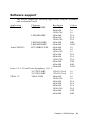
1
PCA-6145B Half-size 486 All-in-one CPU Card with Panel/CRT and Ethernet Interface PCA-6145L Half-size 486 All-in-one CPU Card with Panel/CRT Interface Copyright Notice This document is copyrighted, 1997, by Advantech Co., Ltd. All rights are reserved. Advantech Co., Ltd., reserves the right to make improvements to the products described in this manual at any time without notice. No part of this manual may be reproduced, copied, translated, or transmitted in any form or by any means without the prior written permission of Advantech Co., Ltd. Information provided in this manual is intended to be accurate and reliable. However, Advantech Co., Ltd. assumes no responsibility for its use, nor for any infringements upon the rights of third parties which may result from its use. Acknowledgements AMD is a trademark of Advanced Micro Devices, Inc. Award is a trademark of Award Software International, Inc. IBM, PC AT and VGA are trademarks of International Business Machines Corporation. Microsoft Windows® and MS-DOS are trademarks of Microsoft Corporation. SMC is a trademark of Standard Microsystems Corporation. TGUI 9440 is a trademark of Trident MicroSystems, Inc. Cyrix is a trademark of Cyrix Corporation. Intel is a trademark of Intel Corporation. Part No. 2006145001 1st Edition Printed in Taiwan January 1997 A Message to the Customer.... Advantech Customer Services Each and every Advantech product is built to the most exacting specifications to ensure reliable performance in the unusual and demanding conditions typical of industrial environments. Whether your new Advantech equipment is destined for the laboratory or the factory floor, you can be assured that it will provide the reliability and ease of operation for which the name Advantech has come to be known. Your satisfaction is our number one concern. Here is a guide to Advantech’s customer services. To ensure you get the full benefit of our services, please follow the instructions below carefully. Technical Support We want you to get the maximum performance from your products. If you run into technical difficulties, we are here to help. But please consult this manual first. If you still can’t find the answer, gather all the information or questions that apply to your problem and, with the product close at hand, call your dealer. Our dealers are trained and ready to give you the support you need to get the most from your Advantech products. In fact, most problems reported are minor and are able to be easily solved over the phone. In addition, free technical support is available from Advantech engineers every business day. We are always ready to give advice on application requirements or specific information on the installation and operation of any of our products. Product warranty Advantech warrants to you, the original purchaser, that each of its products will be free from defects in materials and workmanship for one year from the date of purchase. This warranty does not apply to any products which have been repaired or altered by other than repair personnel authorized by Advantech, or which have been subject to misuse, abuse, accident or improper installation. Advantech assumes no liability as a consequence of such events under the terms of this Warranty. Because of Advantech’s high quality-control standards and rigorous testing, most of our customers never need to use our repair and replacement service. If an Advantech product ever does prove defective, it will be repaired at no charge during the warranty period. For out-of-warranty repairs, you will be billed according to the cost of replacement materials, service time and freight. Please consult your dealer for more details. If you think you have a defective product, follow these steps: 1. Collect all the information about the problem encountered (e.g. type of PC, CPU speed, Advantech products used, other hardware and software used etc.). Note anything abnormal and list any on-screen messages you get when the problem occurs. 2. Call your dealer and describe the problem. Please have your manual, product and any other information readily available. 3. If your product is diagnosed as defective, obtain an RMA (return material authorization) number from your dealer. This allows us to process your return more quickly. 4. Carefully pack the defective product, a completely filled-out Repair and Replacement Order Card and a photocopy of a dated proof of purchase (such as your sales receipt) in a shippable container. A product returned without dated proof of purchase is not eligible for warranty service. 5. Write the RMA number visibly on the outside of the package and ship it prepaid to your dealer. Packing list Before you begin installing your card, please make sure that the following materials have been shipped: • 1 PCA-6145B/6145L CPU card • 1 6-pin mini-DIN keyboard & PS/2 mouse adapter • 1 Hard disk drive (IDE) interface cable (40 pin) • 1 Floppy disk drive interface cable (34 pin) • 1 Parallel port adapter (26 pin) and COM2 adapter (9 pin) kit • 1 Utility disk with system VGA BIOS, utility with Win.95 driver & LAN driver • 1 Utility disk with SVGA program and driver for Windows If any of these items are missing or damaged, contact your distributor or sales representative immediately. Contents Chapter 1 Hardware Configuration .......................... 1 Introduction ............................................................................ 2 Specifications .......................................................................... 2 Board layout ........................................................................... 5 Jumpers settings ..................................................................... 8 Jumper settings ....................................................................... 8 How to set jumpers ............................................................... 8 CPU type select .................................................................... 9 Watchdog timer (JP29) ....................................................... 12 COM2 setting for RS-232/422/485 (JP35~39) ................... 12 Battery backup select .......................................................... 12 PS/2 mouse setting .............................................................. 13 LCD type control ................................................................ 13 Chapter 2 Connecting peripherals ......................... 15 Enhanced IDE connectors (CN1) ........................................ 17 VGA interface connection (CN2) ........................................ 17 Floppy drive connector (CN3) ............................................. 18 Parallel port connector (CN4) ............................................. 18 Keyboard & PS/2 mouse connectors (J5) ........................... 19 Reset switch (JP30) ............................................................... 19 Hard disk drive LED (JP3) .................................................. 19 VGA display connector (J2) ................................................ 19 Serial Ports ............................................................................ 19 RS-232 connection (COM1) ............................................... 20 RS-232/422/485 connections (COM2) ................................ 21 Power connectors (J1) ........................................................ 22 Chapter 3 AWARD BIOS SETUP ............................. 23 AWARD BIOS Setup ............................................................ 24 Entering setup ..................................................................... 24 Standard CMOS setup ........................................................ 25 BIOS features setup ............................................................ 26 CHIPSET features setup ..................................................... 30 Power management setup ................................................... 31 Load BIOS defaults ............................................................ 32 Load setup defaults ............................................................. 32 Password setting ................................................................. 32 IDE HDD auto detection ..................................................... 32 Save & Exit setup ............................................................... 32 Exit without saving .............................................................. 32 Chapter 4 VGA Display & Ethernet Software/ Hardware Configuration ........................ 33 Introduction .......................................................................... 34 PCA-6145 Utility Disk .......................................................... 34 VGA Win 95 Driver Support ............................................... 36 Ethernet Driver Support ....................................................... 38 Chapter 5 SVGA Setup ............................................ 39 Simultaneous display mode ................................................. 40 Sleep mode ............................................................................ 40 Software support................................................................... 41 Driver installation ................................................................. 42 Windows setup .................................................................... 43 DOS setup ........................................................................... 44 AutoCAD R12 .................................................................... 46 Lotus 1-2-3 and Lotus symphony ....................................... 48 VESA .................................................................................. 50 Word ................................................................................... 51 Word Perfect ....................................................................... 52 Appendix A Programming the Watchdog Timer .... 55 Appendix B Upgrading ............................................ 57 Installing PC/104 module (CN5, CN6) ............................... 58 Installing DRAM (SIMMs) .................................................. 60 Appendix C Detailed System Information .............. 61 Appendix D POST LEDs .......................................... 71 CHAPTER Hardware Configuration 1 This chapter gives background information on the PCA-6145B/6145L. It then shows you how to configure the card to match your application and prepare it for installation into your PC. Sections include: • Card specifications • Board layout • Safety precautions • Jumper settings • Installing DRAM (SIMMs) Introduction The PCA-6145B/6145L is a full-function CPU card which integrates the VGA LCD panel, Ethernet and other enhanced I/O interfaces on a halfsize CPU card. This card uses a 80486 DX, DX2, DX4 CPU or 5x86 series and can have up to 32 MB DRAM and EDO RAM. It also provides an optional 128 KB cache RAM. The PCA-6145B/6145L offers power management to minimize power consumption. It complies with the "Green Function" standard and supports three power saving features: doze, sleep, and suspended mode. Its high performance VGA display supports both CRT and panel displays with a display memory of up to 1 MB and a resolution of up to 640x480 with 1.6 million colors. The VGA controller is a VL bus C&T 65545, which comes equipped with a windows accelerator. The PCA-6145B/6145L also offers several industrial features such as a 63-level watchdog timer with jumperless setup, supports M-systems DiskOnChip Flash Disk (refer to M-systems Data base and a face-up PC/104 connection for additional functions with PC/104 modules. Specifications System • CPU: Intel AMD Cyrix 80486DX/DX2/DX4 series 80486DX2/DX4 series, 5x86-133 80486DX2/DX4 series, 5x86-100/120 • BIOS: AWARD Flash BIOS, supports plug & play • Chipset: VIA VT82C496G • Secondary level cache: 128 KB • Green function: Supports power management option via BIOS, activated by keyboard or mouse activity. Supports doze, sleep, and suspended mode. APM 1.1 compliant 2 PCA-6145B/6145L User's Manual • RAM: 1 MB to 32 MB, one 72-pin SIMM socket, accepts 1, 2, 4, 8, 16, and 32 MB SIMMs and EDO RAM • EIDE interface: Supports up to two IDE devices. BIOS supports up to 8.4 GB HDD. 32-bit host data transfer, PIO Mode 3 transfer capabilities (>10 MB/sec) • Floppy disk drive interface: Supports up to two floppy disk drives, 5¼” (360 KB and 1.2 MB) and/or 3½” (720 KB, 1.44 MB, and 2.88 MB) • Parallel port: One enhanced parallel port, supports EPP/ECP parallel mode • Serial ports: Two 16C550 UARTs, one RS-232, one RS-232/422/485 interface • Watchdog timer: 63-level timer interval, with jumperless setup, generates system reset or IRQ15 • Keyboard/mouse connector: Mini DIN connector for keyboard and PS/2 mouse, 5-pin male keyboard connector is also available • I/O bus expansion: PC/104 connector with face-up installation • SSD: Supports M-systems DiskOnChip flash disk • Flash Backup: CMOS Data Ethernet controller functions (PCA-6145B only) • Controller: UMC UM9008, built-in 8k x 16 SRAM • I/O address switchless setting • Software compatible with NE-1000 and NE-2000 • Loopback capability for diagnostics • Connector: RJ-45 • Boot ROM: Built-in system BIOS (optional) Chapter 1 Hardware Configuration 3 Local bus VGA functions • Controller: VL-bus C&T 65545 VGA controller with Windows accelerator • Display memory: 1 MB on-board DRAM • Display resolution: Supports resolutions up to 1280 x 1024 - Non-interlaced CRT display up to 1024 x 768 with 256 colors - Flat panel display up to 640 x 480 resolution - Support True-color and Hi-color display capability • Display output: DB-15 VGA connector, 22 x 2 pin header general purpose flat panel display connector • Display BIOS: Default CRT/Toshiba TFT panel BIOS, Flash BIOS can be easily updated Mechanical and environmental • Board size: 185 mm x 122 mm • Max. power requirements: +5 V, 3.5 A • Power supply voltage: +5 V (4.75 V to 5.25 V) • Operating temperature: 32 to 140oF (0 to 60oC) • Storage temperature: -40 to +176°F (-40 to +80oC) • Humidity: 5 to 95%, non-condensing • Board size: 7.3" (L) x 4.8" (W) (185 mm x 122 mm) • Board weight: 1.2 lb. (0.5 kg) 4 PCA-6145B/6145L User's Manual Board layout PCA-6145B/PCA-6145L PCB Layout Chapter 1 Hardware Configuration 5 Jumpers and connectors Connectors on the board link it to external devices such as hard disk drives, a keyboard, or floppy drives. In addition, the board has a number of jumpers which you use to configure it for your application. The table below lists the function of each of the board jumpers and connectors. Later sections in this chapter give instructions on setting jumpers and detailed information on each jumper setting. Chapter 2 gives instructions for connecting external devices to your card. PCA-6145B/PCA-6145L Jumpers Number JP1 JP2 JP3 JP4 JP5 JP6 JP7 JP8 JP9 JP11 JP13 JP14 JP15 JP20, JP21 JP22-JP24 JP28 JP29 JP30 JP35-JP39 6 Function Turbo LED Turbo Switch HDD LED Clock select Clock select Clock select CPU type select CPU type select Battery backup CPU type select CPU type select Voltage selection PS/2 mouse set CPU type select S.S.D. Function set LCD Control Watchdog timer Rest switch COM2 select PCA-6145B/6145L User's Manual PCA-6145B/PCA-6145L Connectors Number CN1 CN2 CN3 CN4 COM1 COM2 J1 J2 J3 J4 J5 J6 J7 Function Enhanced IDE connector LCD connector FDD connector Parallel port connector Serial port 1 connector Serial port 2 connector SBC power connector VGA connector Ethernet connector External Keyboard connector Keyboard connector Keyboard lock Speaker Safety precautions Follow these simple precautions to protect yourself from harm and your PC from damage. 1. To avoid electric shock, always disconnect the power from your PC chassis before you work on it. Don’t touch any components on the CPU card or other cards while the PC is on. 2. Disconnect power before making any configuration changes. The sudden rush of power as you connect a jumper or install a card may damage sensitive electronic components. 3. Always ground yourself to remove any static charge before you touch your CPU card. Be particularly careful not to touch the chip connectors. Modern integrated electronic devices, especially CPUs and memory chips, are extremely sensitive to static electric discharges and fields. Keep the card in its antistatic packaging when it is not installed in the PC, and place it on a static dissipative mat when you are working with it. Wear a grounding wrist strap for continuous protection. Chapter 1 Hardware Configuration 7 Jumper settings This section tells how to set the jumpers to configure your card. It gives the card default configuration and your options for each jumper. After you set the jumpers and install the card, you will also need to run the BIOS Setup program (discussed in Chapter 3) to configure the serial port addresses, floppy/hard disk drive types and system operating parameters. Connections, such as hard disk cables, appear in Chapter 2. For the locations of each jumper, see the board layout diagram depicted earlier in this chapter. How to set jumpers You configure your card to match the needs of your application by setting jumpers. A jumper is the simplest kind of electric switch. It consists of two metal pins and a small metal clip (often protected by a plastic cover) that slides over the pins to connect them. To “close” a jumper you connect the pins with the clip. To “open” a jumper you remove the clip. Sometimes a jumper will have three pins, labeled 1, 2 and 3. In this case you connect either pins 1 and 2 or 2 and 3. 1 Open Closed 2 3 Closed 2-3 You may find pair of needle-nose pliers useful for setting the jumpers. If you have any doubts about the best hardware configuration for your application, contact your local distributor or sales representative before you make any changes. 8 PCA-6145B/6145L User's Manual CPU type select In order for the system to function properly, the jumpers must be set to accommodate the CPU installed on the CPU card. CPU type select CPU Type JP4 JP5 JP6 JP7 JP8 JP11 JP13 JP14 JRN1 JRN2 JRN3 Intel DX-33(5V) DX2-66 Intel P24D DX4-100 (5V) 1 1 1 1 1 1 1 1 1 1 SGS DX4-100 AMD 5x86-133 Intel DX4-100 AMD DX4-100 (SV8B) Cyrix 5x86-100 (3.3V) Chapter 1 Hardware Configuration 9 CPU type select CPU Type JP4 JP5 JP6 JP7 JP8 JP11 JP13 JP14 JRN1 JRN2 JRN3 Cyrix 5x86-120 AMD DX4-120 (3.3V)(SV8B) 10 1 Intel P24D DX4-75 (5V) 1 Cyrix DX2-66 SGS DX2-66 (5V) 1 TI DX2-66 (3.3V) 1 1 1 PCA-6145B/6145L User's Manual 1 1 1 1 1 CPU type select CPU Type JP4 JP5 JP6 JP7 JP8 JP11 JP13 JP14 JRN1 JRN2 JRN3 Cyrix DX2-80 TI DX2-80 (3.3V) 1 AMD DX-40 DX2-80(5V) 1 AMD DX4-100 (NV8T) (3.3 V) 1 1 1 1 1 1 1 1 Note: 1. AMD 5X86-133 JP20 ON other OFF 2. AMD DX2-80 JP21 ON other OFF Default setting: Intel DX4-100 Chapter 1 Hardware Configuration 11 Watchdog timer (JP29) Watchdog timer system reset/IRQ15 select (JP29) Reset (default) IRQ15 1 1 JP29 COM2 settings for RS-232/422/485 (JP35~39) COM2 settings for RS-232/422/485 (COM2) RS-232 (default) RS-422 RS-485 1 2 3 1 2 3 1 2 3 3 2 1 3 2 1 3 2 1 6 5 4 6 5 4 6 5 4 JP35 JP36 JP37 JP38 JP39 Battery backup select Battery Backup (default) JP9 12 1 2 3 PCA-6145B/6145L User's Manual PS/2 mouse setting PS2 Mouse (default) JP15 1 2 3 LCD type control LCD (default) 1 2 3 EL 1 2 3 JP28 Chapter 1 Hardware Configuration 13 14 PCA-6145B/6145L User's Manual CHAPTER Connecting peripherals 2 This chapter tells how to connect peripherals, switches and indicators to the PCA-6145B/PCA-6145L board. You can access most of the connectors from the top of the board while it is installed in the chassis. If you have a number of cards installed, or your chassis is very tight, you may need to partially remove the card to make all the connections. The following table lists the connectors on the PCA-6145B/PCA6145L. Connectors Label CN1 CN2 CN3 CN4 CN5,CN6 JP30 LED1 LED2 Component IDE connector LCD connector FDD connector Parallel port connector PC 104 connector Reset Switch Power LED Ethernet LED The following sections tell how to make each connection. In most cases, you will simply need to connect a standard cable. Warning! Always completely disconnect the power cord from your chassis whenever you are working on it. Do not make connections while the power is on. Sensitive electronic components can be damaged by the sudden rush of power. Only experienced electronics personnel should open the PC chassis. Caution! Always ground yourself to remove any static charge before touching the CPU card. Modern electronic devices are very sensitive to static electric charges. Use a grounding wrist strap at all times. Place all electronic components on a static-dissipative surface or in a static-shielded bag when they are not in the chassis. 16 PCA-6145B/6145L User's Manual Enhanced IDE connectors (CN1) You can attach two IDE (Integrated Device Electronics) drives to the PCA-6145B/PCA-6145L's internal controller. The PCA-6145B/ PCA-6145L CPU card has an EIDE connector, CN1. Wire number 1 on the cable is red or blue, the other wires are gray. Connect one end to connector CN1 on the CPU card. Make sure that the red (or blue) wire corresponds to pin 1 on the connector (on the right side). See Chapter 1 for help finding the connector. Unlike floppy drives, IDE hard drives can connect in either position on the cable. If you install two drives, you will need to set one as the master and one as the slave. You do this by setting the jumpers on the drives. If you use just one drive, you should set it as the master. See the documentation that came with your drive for more information. Connect the first hard drive to the other end of the cable. Wire 1 on the cable should also connect to pin 1 on the hard drive connector, which is labeled on the drive circuit board. Check the documentation that came with the drive for more information. Connect the second drive as described above on CN1. LCD interface connection (CN2) LCD display connector (CN2) CN2 consists of a 44-pin, dual-in-line header. Power supplies (+12V) present on CN2 depend on the supply connected to the board. The PCA-6145B/PCA-6145L provides a bias control signal on CN2 which can be used to control the LCD bias voltage. It is recommended that the LCD bias voltage (+5V) and panel video signals are stable. Under normal operation, the control signal (ENAVEE) is active high. When the PCA-6145B/PCA-6145L's power is applied, the control signal is low until just after the relevant flat panel signal is present. Configuration of the VGA interface is done completely via the software utility. You don't have to set any jumpers. Refer to Chapter 4 for software setup details. Chapter 2 Connecting peripherals 17 Floppy drive connector (CN3) You can attach up to two floppy disk drives to the PCA-6145B/ PCA-6145L's on-board controller. You can use any combination of 5.25" (360 KB and 1.2 MB) and/or 3.5" (720 KB, 1.44 MB and 2.88 MB) drives. The card comes with a 34-pin daisy-chain drive connector cable. On one end of the cable is a 34-pin flat-cable connector. On the other end are two sets of floppy disk drive connectors. Each set consists of a 34-pin flat-cable connector (usually used for 3.5" drives) and a printed-circuit-board connector (usually used for 5.25" drives). You can use only one connector in each set. The set on the end (after the twist in the cable) connects to the A: floppy. The set in the middle connects to the B: floppy. Parallel port connector (CN4) The parallel port is normally used to connect the CPU card to a printer. The PCA-6145B/PCA-6145L includes an on-board parallel port, accessed through a 26-pin flat-cable connector, CN4. The card comes with an adapter cable which lets you use a traditional DB25 connector. The cable has a 26-pin connector on one end and a DB-25 connector on the other, mounted on a retaining bracket. The bracket installs at the end of an empty slot in your chassis, giving you access to the connector. To install the bracket, find an empty slot in your chassis. Unscrew the plate that covers the end of the slot. Screw in the bracket in place of the plate. Next, attach the flat-cable connector to CN4 on the CPU card. Wire 1 of the cable is red or blue, and the other wires are gray. Make sure that wire 1 corresponds to pin 1 of CN4. Pin 1 is on the right side of CN4. 18 PCA-6145B/6145L User's Manual Keyboard & PS/2 mouse connectors (J5) The PCA-6145B/PCA-6145L board provides a keyboard connector. A 6-pin mini-DIN connector (J5) on the card mounting bracket supports single-board computer applications. The card comes with an adapter to convert from the 6-pin mini-DIN connector to a standard DIN connector and to a PS/2 mouse connector. Reset switch (JP30) You can connect an external switch to easily reset your computer. This switch restarts your computer as if you had turned off the power, then turned it back on. Install the switch so that it closes the two pins of JP30. Hard disk drive LED (JP3) You can connect a LED to connector JP3 to indicate when the HDD is active. Marks on the circuit board indicate LED polarity. VGA display connector (J2) The PCA-6145B/PCA-6145L provides a VGA controller for high resolution VGA interface. J2 is a DB-15 connector for VGA monitor input. Serial Ports The PCA-6145B/PCA-6145L offers two serial ports: COM1 in RS232, COM2 in RS-232/422/485. These ports let you connect to serial devices (a mouse, printers, etc.) or a communication network. You can select the address for each port (3F8H [COM1], 2F8H [COM2] or 3E8H, [COM3] or 2E8 [COM4]) or disable it using the BIOS Advanced Setup program, covered in Chapter 3. The card mounting bracket holds the serial port connector for the one port, and the parallel port and serial port adapter kit (supplied Chapter 2 Connecting peripherals 19 with the card) holds the connector for the other port. This lets you connect and disconnect cables after you install the card. The DB-9 connector on the bottom of the bracket is the first RS-232 port, COM1. The DB-9 connector on the adapter kit is the second serial port, COM2. Serial port connections (COM1, COM2) Connector COM1 COM2 Address RS-232 RS-232/422/485 RS-232 connection (COM1) Different devices implement the RS-232 standard in different ways. If you are having problems with a serial device, be sure to check the pin assignments for the connector. The following table shows the pin assignments for the card's RS-232 port: RS-232 connector pin assignments Pin 1 2 3 4 5 6 7 8 9 Signal DCD RX TX DTR GND DSR RTS CTS RI 1 6 5 9 COM1 20 PCA-6145B/6145L User's Manual RS-232/422/485 connection (COM2) COM2 is an RS-232/422/485 serial port. The specific port type is determined by jumper settings JP35 - JP39, as detailed in Chapter 1. The following table shows the pin assignments for COM2. RS-232/485 connector pin assignments Pin 1 2 3 4 5 6 7 8 9 RS-232 DCD RX TX DTR GND DSR RTS CTS RI RS-422/485 TX - or send data - (DTE) TX + or send data + (DTE) RX + or receive data + (DTE) RX - or receive data - (DTE) GND 5 4 3 2 1 NC 9 8 7 6 COM 2 Chapter 2 Connecting peripherals 21 Power connectors J1 If you prefer not to acquire power through PCA-6145B/PCA6145L's backplane via the gold H-connectors, J1 also provide power input connectors for +5 V and +12 V. Warning! Before making the connection, make sure the voltage is absolutely correct and matched with the right connector. 1 2 3 4 5 V + 12 GND GND +512V V J1 22 PCA-6145B/6145L User's Manual 1 2 3 4 GN +5 GN +1 CHAPTER 3 AWARD BIOS SETUP This chapter describes how to set the card’s BIOS configuration data. AWARD BIOS Setup ROM ISA BIOS (2C4L6AKK) CMOS SETUP UTILITY AWARD SOFTWARE, INC. STANDARD CMOS SETUP PASSWORD SETTING BIOS FEATURES SETUP IDE HDD AUTO DETECTION CHIPSET FEATURES SETUP SAVE & EXIT SETUP POWER MANAGEMENT SETUP EXIT WITHOUT SAVING LOAD BIOS DEFAULTS LOAD SETUP DEFAULTS ESC: QUIT ßàáâ: SELECT ITEM F10: Save & Exit Setup (Shift)F2: Change Color Time, Date, Hard Disk Type.... Setup program initial screen Award's BIOS ROM has a built-in Setup program that allows users to modify the basic system configuration. This type of information is stored in battery-backed RAM so that it retains the Setup information when the power is turned off. Entering setup Turning on the computer and pressing <DEL> immediately will allow you to enter Setup. 24 PCA-6145B/6145L User's Manual Standard CMOS setup Choose the "STANDARD CMOS SETUP" option from the INITIAL SETUP SCREEN Menu, and the screen below is displayed. This standard Setup Menu allows users to configure system components such as date, time, hard disk drive, floppy drive, display, and memory. ROM ISA BIOS (2C4L6AKK) STANDARD CMOS SETUP AWARD SOFTWARE, INC. Date (mm:dd:yy) Time (hh:mm:ss) : : Wed, Aug 7 1996 12 : 19 : 58 Drive C : Auto ( Drive D : Auto ( 0Mb) 0Mb) CYLS. HEADS PRECOMP LANDZONE SECTORS MODE Drive A : 1.44M, 3.5 in. Drive B : None Video : EGA/VGA Halt On : All Errors ESC : Quit F1 : Help 0 0 0 0 0 0 0 0 0 0 AUTO AUTO Base Memory : Extended Memory : Other Memory : 640K 7424K 128K Total Memory : 8192K ßàáâ : Select Item (Shift)F2 : Change Color PU / PD / + / - : Modify CMOS setup screen Chapter 3 Award BIOS setup 25 BIOS features setup By choosing the "BIOS FEATURES SETUP" option from the CMOS SETUP screen menu, the following screen is displayed. This sample scree contains the manufacturer's default values for the PCA-6145B/PCA-6145L. ROM ISA BIOS (2C4L6AKK) BIOS FEATURES SETUP AWARD SOFTWARE, INC. Virus Warning CPU Internal Cache External Cache Quick Power On Self Test Boot Sequence Swap Floppy Drive Boot Up Floppy Seek Boot Up NumLock Status Boot Up System Speed IDE HDD Block Mode Gate A20 Option Typematic Rate Setting Typematic Rate (Chars/Sec) Typematic Delay (Msec) Security Option OS Select for DRAM > 64MB : : : : : : : : : : : : : : : : Disabled Enabled Enabled Enabled A,C Disabled Enabled On High Enabled Fast Disabled 6 250 Setup Non-OS2 Video BIOS Shadow C8000-CBFFF Shadow CC000-CFFFF Shadow D0000-D3FFF Shadow D4000-D7FFF Shadow D8000-DBFFF Shadow DC000-DFFFF Shadow Esc F1 F5 F6 F7 : : : : : : : Enabled Disabled Disabled Disabled Disabled Disabled Disabled : Quit ßàáâ: Select Item : Help PU / PD / + / - : Modify : Old Values (Shift)F2 : Color : Load BIOS Defaults : Load Setup Defaults Virus Warning During and after the system boots up, any attempt to write to the boot sector or partition table of the hard disk drive will halt the system. In this case, if Virus Warning is enabled, the following error message will automatically appear: !WARNING! Disk boot sector is to be modified Type "Y" to accept write or "N" to abort write Award Software, Inc. You can run the anti-virus program to locate the problem. If Virus Warning is Disabled, no warning message will appear if anything attempts to access the boot sector or hard disk partition. 26 PCA-6145B/6145L User's Manual CPU Internal Cache/External Cache Depending on the CPU/chipset design, these options can speed up memory access when enabled. Quick Power On Self Test This option speeds up the Power-On Self Test (POST) conducted as soon as the computer is turned on. When enabled, BIOS shortens or skips some of the items during the test. When disabled, normal POST procedures assumes. Boot Sequence This function determines the sequence in which the computer will search the drives for the disk operating system (i.e. DOS). The default value is "A, C". C,A A,C System will first search the hard drive, then the floppy drive. System will first search the floppy drive, then the hard drive. Boot Up Floppy Seek During POST, BIOS will determine if the floppy disk drive installed is 40 or 80 tracks. 360 KB type is 40 tracks while 720 KB, 1.2 MB, and 1.44 MB are all 80 tracks. Enabled BIOS searches the floppy drive to determine if it is 40 or 80 tracks. Note that BIOS cannot differentiate 720 KB, 1.2 MB, and 1.44 MB type drives as they are all 80 tracks. Disabled BIOS will not search for the floppy drive type by track number. Note that there will not be any warning message if the drive installed is 360 KB. Boot Up NumLock Status The default is "On". On Off Keypad boots up to number keys. Keypad boots up to arrow keys. Chapter 3 Award BIOS setup 27 Boot Up System Speed High Low Sets the speed to high Sets the speed to low IDE HDD Block Mode Enabled Enable IDE HDD Block Mode. BIOS will detect the block size of the HDD and send a block command automatically. Disabled Disable IDE HDD Block Mode Gate A20 option Normal Fast The A20 signal is controlled by the keyboard controller or chipset hardware Default: Fast. The A20 signal is controlled by Port 92 or chipset specific method. Typematic Rate setting The typematic rate determines the characters per second accepted by the computer. Typematic Rate setting enables or disables the typematic rate. Typematic Rate (Char/Sec) BIOS accepts the following input values (character/second) for Typematic Rate: 6, 8, 10, 12, 15, 20, 24, 30. Typematic Delay (msec) When holding down a key, the Typematic Delay is the time interval between the appearance of the first and second characters. The input values (msec) for this category are: 250, 500, 750, 1000. Security Option This setting determines whether the system will boot if the password is denied, while limiting access to Setup. System Setup 28 The system will not boot, and access to Setup will be denied if the correct password is not entered at the prompt. The system will boot, but access to Setup will be denied if the correct password is not entered at the prompt. PCA-6145B/6145L User's Manual Note: To disable security, select PASSWORD SETTING in the main menu. At this point, you will be asked to enter a password. Simply hit the <ENTER> key to disable security. When security is disabled, the system will boot, and you can enter Setup freely. OS select for DRAM>64 MB. This setting is underOS/2 system. Video BIOS Shadow This determines whether video BIOS will be copied to RAM, which is optional according to the chipset design. When enabled, Video Shadow increases the video speed. C8000 - CFFFF Shadow/DC000-DFFFF Shadow These determine whether optional ROM will be copied to RAM in blocks of 16 KB. Enabled Optional shadow is enabled Disabled Optional shadow is disabled Chapter 3 Award BIOS setup 29 CHIPSET features setup By choosing the "CHIPSET FEATURES SETUP" option from the CMOS SETUP screen menu, the following screen is displayed. This sample screen contains the manufacturer's default values for the PCA-6145 board. ROM ISA BIOS (2C4L6AKK) CMOS SETUP UTILITY CHIPSET FEATURES SETUP Auto Configuration : Decoupled Refresh : Video BIOS Cacheable : System BIOS Cacheable : External Cache Scheme : Combine Alter & Tag Bits : CHRDY for ISA master : Memory Hole at 15MB Addr. : Cache Timing Control : DRAM Timing Control : FAST DRAM : CPU Write Back Cache : Set Turbo pin function : Set Mouse clock : LAN Card Boot ROM : 30 Enabled Enabled Enabled Enabled Write back Enabled Enabled Disabled Normal Normal Disabled Disabled Turbo Disabled Disabled PCA-6145B/6145L User's Manual On-Board Local-Bus IDE IDE Primary Master PIO IDE Primary Slave PIO Onboard FDC controller On-board Serial Port 1 On-board Serial Port 2 Onboard Parallel Port Onboard Parallel Mode Esc F1 F5 F6 F7 : : : : : : : : Enabled Auto Auto Enabled COM 1/3F8 COM 2/2F8 378/IRQ7 SPP : Quit ßàáâ: Select Item : Help PU/PD/+/- : Modify : Old Values (Shift)F2 : Color : Load BIOS Defaults : Load Setup Defaults Power management setup The power management setup controls the CPU board's "green" features. The following screen shows the manufacturer's default. ROM ISA BIOS (2C4L6AKK) CMOS SETUP UTILITY POWER MANAGEMENT SETUP Power Management Doze Timer : Disabled : 32 sec Sleep Timer Sleep Mode HDD Power Management VGA Activity Wakeup : : : : IO Activity : Disabled 2 min Disabled Disabled Disabled IRQ3 Activity IRQ4 Activity IRQ5 Activity IRQ7 Activity IRQ8 Activity IRQ10 Activity IRQ11 Activity IRQ12 Activity : : : : : : : : Primary Primary Primary Primary Secondary Primary Primary Primary Esc:Quit ßàáâ: Select Item F1 : Help PU/PD/+/-: Modify F5 : Old Values (Shift)F2 : Color F6 : Load BIOS Defaults F7 : Load Setup Defaults Power Management This option allows you to determine if the values in power management are disabled, user-defined, or predefined. HDD Power Management You can choose to turn the HDD off after a one of the time interval listed, or when the system is in Suspend mode. If in a power saving mode, any access to the HDD will wake it up. Note: HDD will not power down if the Power Management option is disabled. IRQ Activity IRQ can be set independently. Activity on any enabled IRQ will wake up the system. Chapter 3 Award BIOS setup 31 Load BIOS defaults "LOAD BIOS DEFAULTS" indicates the most appropriate values for the system parameters for minimum performance. These default values are loaded automatically if the stored record created by the Setup program becomes corrupted (and therefore unusable). Load setup defaults "LOAD SETUP DEFAULTS" loads the values required by the system for maximum performance. Password setting To change, confirm, or disable the password, choose the "PASSWORD SETTING" option form the Setup main menu and press [Enter]. The password can be at most 8 characters long. Remember, to enable this feature. You must first select the Security Option in the BIOS FEATURES SETUP to be either "Setup" or "System." IDE HDD auto detection "IDE HDD AUTO DETECTION" automatically self-detect for the correct hard disk type. Save & Exit setup If you select this and press the [Enter] key, the values entered in the setup utilities will be recorded in the CMOS memory of the chipset. The microprocessor will check this every time you turn your system on and compare this to what it finds as it checks the system. This record is required for the system to operate. Exit without saving Selecting this option and pressing the [Enter] key lets you exit the Setup program without recording any new values or changing old ones. 32 PCA-6145B/6145L User's Manual CHAPTER 4 VGA Display & Ethernet Software/Hardware Configuration This chapter details the software configuration information. It shows you how to configure the board to match your application requirements. AWARD System BIOS is covered in Chapter 4. Sections include: • LCD display configuration • Connections for two standard LCDs • Ethernet interface configuration Introduction The PCA-6145B/PCA-6145L system BIOS and custom drivers are located in a 128 Kbyte, 32-pin (JEDEC spec.) Flash ROM device, designated U11. A single Flash chip holds the system BIOS, VGA BIOS, and Back-up CMOS Data. The display can be configured via software. This method minimizes the number of chips and eases configuration. You can change the display BIOS simply by reprogramming the Flash chip. PCA-6145B/PCA-6145L Utility Disk The PCA-6145B/PCA-6145L is supplied with a software utility disk that holds the necessary file for setting up the VGA display and Ethernet and Win 95 controller. The disk’s directory and file structure is as follows: ROOT VGAWIN 95 LAN Driver Utility DIAG9008.EXE VGABIOS AWDFLASH.EXE CBROM.EXE 45 BV10.BIN 45B-MONO.BIN 45B-CRT.BIN 45B-EL.BIN 45B-STN.BIN DIAG9008.EXE This program is the UMC9008 Ethernet controller AUTO-Scan/ Setup/Diagnostic function. 45B-CRT.BIN Supports CRT only. 45 BV10.BIN(default) Supports 640 x 480 color TFT (Sharp LQ9D011, Toshiba LTM09C015A/016) 34 PCA-6145B/6145L User's Manual 45B-STN.BIN (512KB VRAM) Support 640 x 480 color STN DD 8/16-bit displays (Sharp LM64C142) Note: This BIOS does not support simultaneous CRT and flat panel display with 512KB VRAM. 45B-MONO.BIN Supports 640 x 480 dual scan monochrome displays (Sharp LM64P8X/837) 45B-EL.BIN Supports 640 x 480 EL displays (PLANAR EL640480-A Series) CBROM.EXE This program allows you to combine your own VGA BIOS with the System BIOS. VGA Display Software Configuration The PCA-6145B/PCA-6145L’s on-board VGA interface supports a wide range of popular LCD, EL, gas plasma flat panel displays and traditional analog CRT monitors. The interface can drive CRT displays with resolutions up to 1024 x 768 in 256 colors. It is also capable of driving color panel displays with resolutions of 640 x 480 in 64K colors. The VGA interface is configured completely via the software utility, so you don’t have to set any jumpers. Configure the VGA display as follows: 1. Apply power to the PCA-6145B/PCA-6145L with a color TFT display attached. This is the default setting for the PCA-6145B/ PCA-6145L. Ensure that the AWDFLASH.EXE and *.BIN files are located in the working drive. NOTE: Ensure that you do not run AWDFLASH.EXE while your system is operating in EMM386 mode. Chapter 4 VGA Display & Ethernet Software/Hardware Configuration 35 2. At the prompt, type AWDFLASH.EXE and press <Enter>. The VGA configuration program will then display the following: VGA Setup screen 3. At the prompt, type in the BIN file which supports your display. When you are sure that you have entered the file name correctly press <Enter>. The screen will ask “Do you want to save?” If you wish to continue press Y. If you change your mind or have made a mistake press N to abort and end the setup procedure. 4. If you decide to continue, the program will create a BIOS.OLD file which contains the existing BIOS configuration. The prompt will then ask “Are you sure you want to save new configuration?” Press Y if you want the new file to be written into the BIOS. Press N to exit the program. The new VGA configuration will then write to the ROM BIOS chip. This configuration will remain the same until you run the AWDFLASH.EXE program and change the settings. VGA Win 95 Driver Support These drivers are designed to work with Microsoft Windows 95. You may install these drivers through Windows 95. 36 PCA-6145B/6145L User's Manual Ethernet Software Configuration The PCA-6145B’s on-board Ethernet interface supports all major network operating systems. I/O addresses and interrupts are easily configured via the DIAG 9008.EXE program. To execute the configuration, to view the current configuration, or to run diagnostics, do the following: 1. Power the PCA-6145B on. Ensure that the DIAG 9008.EXE file is located in the working drive. 2. At the prompt type DIAG 9008.EXE and press <Enter>. The Ethernet configuration program will then be displayed. 3. This simple screen shows all the available options for the Ethernet interface. Just highlight the option you wish to change by using the Up and Down keys. To change a selected item, press <Enter>, and a screen will appear with the available options. Highlight your option and press <Enter>. Each highlighted option has a helpful message guide displayed at the bottom of the screen for additional information. 4. After you have made your selections and are certain it is the configuration that you want, press ESC. A prompt will appear asking if you want to save the configuration. Press Y if you want to save. The Ethernet Setup Menu also offers three very useful diagnostic functions. These are: 1. Run EEPROM test 2. Run Diagnostics on Board 3. Run Diagnostics on Network Each option has its own display screen which shows the format and result of any diagnostic tests undertaken. Note: Ethernet cannot use IRQ12. Because IRQ12 is assigned to PS/2 Mouse. Chapter 4 VGA Display & Ethernet Software/Hardware Configuration 37 Ethernet Driver Support These drivers are designed to work in a workstation environment under Windows NT, Win 95, or DOS operating system. You may install these drivers for your application. 38 PCA-6145B/6145L User's Manual CHAPTER SVGA Setup 5 The PCA-6145B/PCA-6145L features an on-board flat panel/VGA interface. This chapter provides instructions for installing and operating the software drivers on the included display driver diskette. Simultaneous display mode The 65545 VGA BIOS supports monochrome LCD, EL, color TFT and STN LCD flat panel displays. It also supports interlaced and non-interlaced analog monitors (VGA color and VGA monochrome) in high-resolution modes while maintaining complete IBM VGA compatibility. Digital monitors (i.e. MDA, CGA, and EGA) are NOT supported. Multiple frequency (multisync) monitors are supported as analog monitors. Both CRT and panel displays can be used simultaneously. The PCA-6145B/PCA-6145L can be set in one of three configurations: on a CRT, on a flat panel display, or on both simultaneously. The system is initially set to simultaneous display mode. In the utility diskette, there are three .COM files which can be used to select the display. Simply type the filename at the DOS prompt: CT.COM Enables CRT display only FP.COM Enables panel display only SM.COM Enables both displays at the same time. Sleep mode The display driver diskette contains two files that support sleep mode. Simply type the filename at the DOS prompt: ON.COM switches to normal display mode. OFF.COM switches to sleep mode. 40 PCA-6145B/6145L User's Manual Software support The drivers support the following applications using the filenames and resolutions listed: Application Windows 3.1 Filename LINEAR4.DRV LINEAR8.DRV AutoCAD R12 LINEAR16.DRV LINEAR24.DRV RCTURBOC.EXP Resolution 640x480 800x600 1024x768 640x480 800x600 1024x768 640x480 640x480 640x480 800x600 1024x768 640x480 800x600 1024x768 640x480 640x480 640x480 Lotus 1-2-3 2.0 and Lotus Symphony 1.0,1.1 V132X25.DRV 132x25 (Text) V132X50.DRV 132x50 (Text) VESA 1.2 VESA.COM 800x600 1024x768 640x400 640x480 800x600 1024x768 640x480 640x480 Colors 16 16 16 256 256 256 64K 16M 16 16 16 256 256 256 32K 64K 16M 16 16 16 16 256 256 256 256 32K 64K Chapter 5 SVGA Setup 41 Word 5.0 Word 5.5 WordPerfect 5.0 WordPerfect 5.1 VGA600.VID VGA768.VID VGA55600.VID VGA55768.VID CHIPS600.WPD CHIPS768.WPD VGA600.VRS VGA768.VRS 800x600 1024x768 800x600 1024x768 800x600 1024x768 800x600 1024x768 16 16 16 16 16 16 16 16 Driver installation Necessary prerequisites The instructions in this manual assume that you understand elementary concepts of MS-DOS and the IBM Personal Computer. Before you attempt to install any driver or utility you should: know how to copy files from a floppy disk to a directory on the hard disk, understand the MS-DOS directory structure, and know how to format a floppy disk. If you are uncertain about any of these concepts, please refer to the DOS or Windows user reference guides for more information before you proceed with the installation. Before you begin Before you begin installing software drivers, you should make a backup copy of the display driver diskette and store the original in a safe place. The display driver diskette contains drivers for several versions of certain applications. You must install the correct version in order for the driver to work properly so make sure you know which version of the application you have. 42 PCA-6145B/6145L User's Manual Windows setup These drivers are designed to work with Microsoft Windows 3.1. You may install these drivers through Windows or in DOS. Step 1: Install Windows as you normally would for a VGA display. Run Windows to make sure that it is working correctly. Step 2: Place the display driver diskette in drive A. In Windows Program Manager, choose File from the Options Menu. Then from the pull-down menu, choose Run . . . . At the command line prompt, type A:\WINSETUP. Press the <ENTER> key or click OK to begin the installation. At this point the setup program locates the directory where Windows is installed. For proper operation, the drivers must be installed in the Windows subdirectory. Press <ENTER> to complete the installation. Once completed, the Display Driver Control Panel appears on the screen. This Control Panel allows you to select and load the installed drivers. Another method of installing these drivers is through the File Manager. Click on Drive A:. Then double-click on WINSETUP.EXE to begin installation. Changing Display Drivers in Windows To change display drivers in Windows, select the Windows Setup icon from the Main window. You will be shown the current setup configuration. Select Change System Settings from the Option menu. Click on the arrow at the end of the Display line. You will be shown a list of display drivers. Click on the driver you want. Then click on the OK button. Follow the directions to complete the setup. Changing Color Schemes After you change display drivers, you may notice that the color scheme used by Windows looks strange. This is because different drivers have different default colors. To change the color scheme, select the Control Panel from the Main window. Select the Color icon. You will be shown the current color scheme. Choose a new color scheme and click the OK button. Chapter 5 SVGA Setup 43 DOS Setup Step 1: Install Windows as you normally would for a VGA display. Run Windows to make sure that it is working correctly. Then exit Windows. Step 2: Place the display driver diskette in drive A. Type A: <ENTER> to make this the default drive. Type SETUP <ENTER> to run the driver SETUP program. Press any key to get to the applications list. Using the arrow keys, select Windows Version 3.1 and press the <ENTER> key. Press the <ENTER> key to select All Resolutions, and then press <END> to begin the installation. At this point you will be asked for the path to your Windows System directory (default C:\WINDOWS). When the installation is complete, press any key to continue. Press <ESC> followed by Y to exit to DOS. Step 3: Change to the directory where you installed Windows (usually C:\WINDOWS). Step 4: Type SETUP <ENTER> to run the Windows Setup program. It will show the current Windows configuration. Use the up arrow key to move to the Display line and press <ENTER>. A list of display drivers will be shown. Use the arrow keys to select one of the drivers starting with an asterisk (*) and press <ENTER>. Step 5: Follow the directions on the screen to complete the setup. In most cases, you may press <ENTER> to accept the suggested option. When Setup is done, it will return to DOS. Type WIN <ENTER> to start Windows with the new display driver. Changing Display Drivers in DOS To change display drivers from DOS, change to the Windows directory and run Setup, repeating steps 4 and 5 from the previous page. Besides the special display drivers marked by an asterisk (*), you should be able to use the following standard drivers: 44 VGA 640x480, 16 colors Super VGA 800x600, 16 colors PCA-6145B/6145L User's Manual Panning Drivers Special panning drivers are provided to allow high-resolution modes to be displayed on a flat panel or CRT. These drivers will show a section of a larger screen and will automatically pan, or scroll, the screen horizontally and vertically when the mouse reaches the edge of the display. Linear Acceleration Drivers A special high-performance linear acceleration driver is provided for 256-color modes. This driver may require special hardware and may not be supported on all systems. It is only available for Windows3.1. Chapter 5 SVGA Setup 45 AutoCAD R12 These drivers are designed to work with Autodesk AutoCAD R12. They conform to the Autodesk Device Interface (ADI) for Rendering drivers and Display drivers. These display list drivers accelerate redraw, pan, and zoom functions. Driver installation Step 1: Place the display driver diskette in drive A. Type A: <ENTER> to make this the default drive. Type SETUP <ENTER> to run the SETUP program. Press any key to get to the applications list. Using the arrow keys, select AutoCAD Release 12 and press <ENTER>. This will display a list of supported driver resolutions. Using the arrow keys and the <ENTER> key, select the resolutions that are appropriate for your monitor. When all of the desired resolutions have been selected, press <END> to begin the installation. At this point you will be asked for a drive and directory to copy the driver files. Enter the drive and directory that contains the installed AutoCAD R12. If the destination directory does not exist you will be asked for confirmation. When the installation is complete, press any key to continue. Press <ESC> followed by Y to exit to DOS. Step 2: Go to the AutoCAD directory where the new drivers were installed and run the driver installation program by typing ACAD12 -r <ENTER>. This program will configure your AutoCAD R12 to use the new display drivers. Select TurboDLD Classic. Configuring TurboDLD Select Configure Video Display. In Display Device Configuration choose Select Graphics Board/Resolution. Then choose Select Display Graphics Board. After choosing a graphics board, go to Select Display Resolution. After selecting the display resolution, save the new configuration, and return to the main menu. 46 PCA-6145B/6145L User's Manual Basic Configuration Menu This menu allows you to modify: Number of AutoCAD Command Lines Font Size 6x8/8x8/8x14/8x16/12x20/12x24 Dual Screen Enable/Disable User Interface Configuration Double Click Interval Time BP Button BP Highlight Patt Line/Xor Rect/Both BP Refresh Enable/Disable BP Cache Enable/Disable Expert Configuration Menu This menu allows you to modify: Display List Enable/Disable Drawing Cache Enable/Disable Use Acad 31 bit space? Yes/No Internal Command Echo Enable/Disable BP Zoom Mode Freeze/Float Regen Mode Incremental/Fast If your previously installed driver is not TurboDLD, you will have to reconfigure the RENDER command the first time you use it. Chapter 5 SVGA Setup 47 Lotus 1-2-3 and Lotus Symphony These drivers are designed to work with Lotus 1-2-3 versions 2.0, 2.01 and 2.2, and with Lotus Symphony versions 1.0 and 1.1. Driver installation Step 1: Place the display driver diskette into drive A. Make A the default drive by typing A: <ENTER>. Run the SETUP program by typing SETUP <ENTER>. Press any key to display a list of supported applications. Use the arrow keys to select Lotus/ Symphony, and press <ENTER>. A list of supported screen resolutions will be displayed. Use the arrow keys to select the desired screen resolution and press <ENTER>. (Make sure your monitor is able to display the resolution desired) Press <END> to begin the driver installation process. A default drive and directory path will be displayed. Use the backspace key to erase this default and type in the 123 directory. At this point you may be asked to create the target directory if it does not already exist. After the files have been installed, press any key to return to the list of supported applications. Press <ESC> followed by Y to exit to DOS. Copy all the files that were just created in the temporary directory onto a formatted floppy diskette. Step 2: Go to your 123 directory, and start the installation program. Type the following commands: C: <ENTER> INSTALL <ENTER> Step 3: The Lotus installation program will load and present the installation menu. From this menu, select Advanced Options. From the Advanced Options menu, select Add New Drivers To Library. From the Add New Drivers Menu, select Modify Current Driver Set. From the Modify Driver Set Menu, select Text Display. From the Text Display menu, select one of drivers. Step 4: After the selection of the appropriate VGA display driver, you will need to exit this menu and return to the Main Lotus Installation Menu. Do this by selecting Return To Menu. Step 5: At the Main Lotus Installation Menu, select Save Changes. 48 PCA-6145B/6145L User's Manual Step 6: At this point the Installation Menu will prompt you for the name of your new Lotus configuration file. The Lotus system will prompt you with the default value — 123.SET, but you may want to use a filename that indicates the resolution of its driver. For example, if you installed the 132 column by 25 line driver, you could name this driver 132X25.SET, or if you installed the 80 by 50 driver, you may want to call the file 80X50.SET. Step 7: The installation of your Lotus 1-2-3 driver is now complete. You will need to exit the Lotus installation program at this point. At the main Lotus Installation Menu, select Exit. NOTE: If your driver set is not 123.SET, you have to type the filename of your driver set in the command line when you start Lotus 1-2-3. For example, if you named your driver set 132X25.SET, type the following to start Lotus 1-2-3: 123 132X25.SET <ENTER> Chapter 5 SVGA Setup 49 VESA The Video Electronics Standards Association (VESA) has created a standard for a Super VGA BIOS Extension (VBE). This defines a standard software interface to allow application programs to set and control extended video modes, such as 800x600 graphics, on video adapters from different manufacturers. The VESA driver adds this Super VGA BIOS Extension to the VGA BIOS. Any application program which supports the VESA standard driver interface can be used with this driver. This VESA driver conforms to the VESA Super VGA Standard #VS891001. Driver installation Step 1: Place the display driver diskette into drive A. Make A the default drive by typing A: <ENTER>. Run the SETUP program by typing SETUP <ENTER>. Press any key to display a list of supported applications. Use the arrow keys to select VESA Driver Version 1.2 and press <ENTER>. Press the <ENTER> key to select All Resolutions, and press <END> to begin the installation. A default drive and directory path will be displayed. Use the backspace key to erase this and type in a directory that is in the directory path (such as C:\BIN or C:\UTILS). After the files have been installed, press any key to return to the list of supported applications. Press <ESC> followed by Y to exit to DOS. Step 2: To install the VESA driver, type either VESA <ENTER> or VESA + <ENTER> at the DOS prompt. The optional + command line parameter enables all of the available modes. Make sure that your monitor is capable of displaying these high resolution modes before enabling them. NOTE: If the video BIOS already supports VBE extended video modes, DO NOT use this driver. Run the VTEST.EXE program to see if the video BIOS supports the VBE modes. 50 PCA-6145B/6145L User's Manual Word These drivers are designed to work with Microsoft Word 5.0 and 5.5. Driver installation If you have already installed Word on your computer, go to Step 2 to install the new video driver. Step 1: Install Word as normal. Step 2: After you complete the Word installation, place the display driver diskette into drive A. Make A the default drive by typing A: <ENTER>. Run the SETUP program by typing SETUP <ENTER>. Press any key to display a list of supported applications. Use the arrow keys to select Word and press <ENTER>. Use the arrow keys to select the desired screen resolution and press <ENTER> (make sure your monitor is able to display the resolution desired). Press <END> to begin the driver installation process. A default drive and directory path will be displayed. Use the backspace key to erase this and type in your Word directory. After the files have been installed, press any key to return to the list of supported applications. Press <ESC> followed by Y to exit to DOS. Step 3: Copy the driver file for the desired resolution that was just installed to SCREEN.VID. Chapter 5 SVGA Setup 51 WordPerfect These drivers are designed to work with WordPerfect 5.0 or 5.1. They support 132-column display in editing mode, and highresolution graphics display in PreView mode. Driver installation Step 1: Place the display driver diskette into drive A. Make A the default drive by typing A: <ENTER>. Run the SETUP program by typing SETUP <ENTER>. Press any key to display a list of supported applications. Use the arrow keys to select WordPerfect and press <ENTER>. A list of supported screen resolutions will be displayed. Use the arrow keys to select the desired screen resolution and press <ENTER> (make sure your monitor is able to display the resolution desired). Press <END> to begin the driver installation process. A default drive and directory path will be displayed. Use the backspace key to erase this default and type in the WordPerfect directory. At this point you may be asked to create the target directory if it does not already exist. After the files have been installed, press any key to return to the list of supported applications. Press <ESC> followed by Y to exit to DOS. Step 2: Start WordPerfect, and press <SHIFT>+<F1> to enter the setup menu. Select D for Display and G for Graphics Screen Type, and then choose the desired Chips VGA resolution. 52 PCA-6145B/6145L User's Manual Configuring WordPerfect 5.0 for 132 columns Follow these instructions to configure WordPerfect 5.0 for 132 column text mode: Step 1: To use the SETCOL program to set 132 columns and 25 rows, type the following command: SETCOL 132, 25 <ENTER> Step 2: Start WordPerfect. The program will detect the number of rows and columns automatically. If for some reason WordPerfect is unable to adapt to 132 columns by 25 rows, start WordPerfect with the following command: WP /SS=25,132 <ENTER> Configuring WordPerfect 5.1 for 132 columns Start WordPerfect and press <SHIFT>+<F1> to enter the setup menu. Select D for Display and T for Text Screen Type and then select Chips 132 Column Text. Chapter 5 SVGA Setup 53 54 PCA-6145B/6145L User's Manual Appendix A Programming the Watchdog Timer The PCA-6145B/PCA-6145L is equipped with a watchdog timer that resets the CPU or generates an interrupt if processing comes to a standstill for whatever reason. This feature ensures system reliability in industrial stand-alone and unmanned environments. Programming the watchdog timer If you decide to program the watchdog timer, you must write a program which reads I/O port address 443 (hex). The output data is a timer value. You can write it from 01 (hex) to 3F (hex), and the related timer is 1 sec. to 63 sec. After date entry, your program must refresh the watchdog dimer by rewriting the I/O port 443 (hex) while simultaneously setting it. The following program is a program for the watchdog timer:: Step 1 Step 2 Step 3 Step 4 Step 5 . . Step n out 443h, data REM Start and reset the watchdog timer your application program task #1 out 443h, date REM Reset the timer your application program task #2 out 443h, data REM Reset the timer . . in 43h REM Disable watchdog function Date values 01 1 sec. 02 2 sec. 03 3 sec. 04 4 sec. . . . . . . . . 3F 63 sec 56 PCA-6145B/6145L User's Manual APPENDIX Upgrading B This appendix gives instructions for increasing the capabilities of your CPU card. It covers: • Installing PC/104 • DRAM memory installation (SIMMs) Installing PC/104 modules (CN5,CN6) The PCA-6145B/PCA-6145L card's PC/104 connector lets you attach PC/104 modules. These modules perform the functions of traditional plug-in expansion cards, but save space and valuable slots. Advantech modules include: • PCM-3110 PCMCIA module • PCM-3718 30 KHz A/D module • PCM-3724 48-channel DIO module PC/104 modules are produced by over a dozen manufacturers, and the PC/104 form factor is being advanced as an appendix to the ISA bus standard. If you want to make your own PC/104 module, the figure on the following page shows module dimensions. A PC/104 breadboard module (PCM-3910) is also available. Pin assignments for the connector appear in Appendix D. For further information, contact your Advantech distributor or sales representative. 58 PCA-6145B/6145L User's Manual PC/104 module dimensions (mm) Appendix B Upgrading 59 Installing DRAM (SIMMs) You can use anywhere from 1 MB to 32 MB of DRAM with your PCA-6145B/PCA-6145L. The card provides one 72-pin SIMM (single in-line memory module) socket that accepts from 1 to 32 MB DRAM or EDO RAM. The following table shows the bank assignment for the SIMM socket: Bank SIMM socket(s) Size 1 SIMM1 72-pin You can use 256 KBx32, 256 KBx64, 1 MBx32, 1 MBx64, 4 MBx32 or 4 MBx64 DRAM SIMMs. Memory sizes The board accepts 1 MB, 2 MB, 4 MB, 8 MB, 16 MB, 32 MB and EDO RAM. The following table lists some of the different memory configurations for the PCA-6145B/PCA-6145L card. SIMM 1 Total 1 MB 2 MB 4 MB 8 MB 16 MB 32MB 1 MB 2MB 4 MB 8 MB 16 MB 32MB Supported Memory Configurations 60 PCA-6145B/6145L User's Manual APPENDIX Detailed system information C This appendix contains information of a detailed or specialized nature. It includes: • • • • • Parallel connector pin assignments HDD connector pin assignments FDD connector pin assignments Keyboard connector pin assignments CRT display connector • Flat panel display connector • RS-232 connections • PC/104 connector pin assignments • System I/O port address assignments • System information I/O address assignments • • • • • DMA channel assignments DMA controller registers DMA page addresses Interrupt assignments Timer channel assignments Parallel/printer connector (CN4) Pin no. 1 2 3 4 5 6 7 8 9 10 11 12 13 14 15 16 17 18-25 Signal STROBE DATA 0 DATA 1 DATA 2 DATA 3 DATA 4 DATA 5 DATA 6 DATA 7 - ACKNOWLEDGE BUSY PAPER EMPTY + SELECT - AUTO FEED - ERROR - INIT PRINTER - SELECT INPUT GROUND HDD connector (CN1) Pin no. Signal 1 - RST 3 D7 5 D6 7 D5 9 D4 11 D3 13 D2 15 D1 17 D0 19 GND 21 N.C. 23 IOW 25 IOR 62 Pin no. Signal 2 GND 4 D8 6 D9 8 D10 10 D11 12 D12 14 D13 16 D14 18 D15 20 N.C. 22 GND 24 GND 26 GND PCA-6145/6145L User's Manual Pin no. Signal 27 IORDY 29 N.C. 31 IRQ 33 A1 35 A0 37 CSO 39 -ACT Pin no. Signal 28 BALE 30 GND 32 -IO CS16 34 N.C. 36 A2 38 CS1 40 GND FDD connector (CN3) Pin no. 1-33 (odd) 2 4, 6 8 10 12 14 16 18 20 22 24 26 28 30 32 34 Signal GROUND HIGH DENSITY UNUSED INDEX MOTOR ENABLE A DRIVER SELECT B DRIVER SELECT A MOTOR ENABLE B DIRECTION STEP PULSE WRITE DATA WRITE ENABLE TRACK 0 WRITE PROTECT READ DATA SELECT HEAD DISK CHANGE Keyboard connector pin assignment (J4, J5) J4 1 2 3 (NC) 4 5 J5 5 1 2 3 4 6 Signal CLOCK DATA PS/2 DATA GND +5 V PS/2 CLOCK Appendix C Detailed system information 63 VGA display connector (J2) PCA-6145 CRT display connector Pin 1 2 3 4 5 6 7 8 Signal RED GREEN BLUE N/C GND GND GND GND Pin 9 10 11 12 13 14 15 Signal N/C GND N/C N/C H-SYNC V-SYNC N/C Flat panel display connector (CN2) mini pin header PCA-6145 Flat panel display connector Pin 1 3 5 7 9 11 13 15 17 19 21 23 25 27 29 31 33 35 37 39 41 43 64 Function +12 V GND Vcc ENAVEE P0 P2 P4 P6 P8 P10 P12 P14 P16 P18 P20 P22 GND SHFCLK M GND KB-DATA NC PCA-6145/6145L User's Manual Pin 2 4 6 8 10 12 14 16 18 20 22 24 26 28 30 32 34 36 38 40 42 44 Function +12 V GND Vcc GND P1 P3 P5 P7 P9 P11 P13 P15 P17 P19 P21 P23 GND FLM LP ENABKL KB-CLK NC RS-232 connections (COM1, COM2) Different devices implement the RS-232 standard in different ways. If you are having problems with a serial device, be sure to check the pin assignments for the connector. The following table shows the pin assignments for the card's RS-232 port: RS-232 connector pin assignment Pin 1 2 3 4 5 6 7 8 9 Signal DCD RX TX DTR GND DSR RTS CTS RI 1 6 5 9 COM1 5 74 53 32 1 9 NC NC89 68 47 6 COM2 Appendix C Detailed system information 65 PC/104 Connector Pin Assignments 0 1 2 3 4 5 6 7 8 9 10 11 12 13 14 15 16 17 18 19 20 21 22 23 24 25 26 27 28 29 30 31 32 CN5 --IOCHCHK* 0V SD7 RESETDRV SD6 +5V SD5 IRQ9 SD4 -5V SD3 DRQ2 SD2 -12V SD1 OWS* SD0 +12 IOCHRDY NC AEN SMEMW* SA19 SMEMR* SA18 IOW* SA17 IOR* SA16 DACK3* SA15 DRQ3 SA14 DACK1* SA13 DRQ1 SA12 REFRESH* SA11 SYSCLK SA10 IRQ7 SA9 IRQ6 SA8 IRQ5 SA7 IRQ4 SA6 IRQ3 SA5 DACK2* SA4 TC SA3 BALE SA2 +5V SA1 OSC SA0 0V 0V 0V * Low active single --none 66 PCA-6145/6145L User's Manual CN6 0V 0V SBHE* MEMCS16* LA23 IOCS16* LA22 IRQ10 LA21 IRQ11 LA20 IRQ12 LA19 IRQ15 LA18 IRQ14 LA17* DACK0* MEMR* DRQ0* MEMW* DACK5* SD8 DRQ5 SD9 DACK6* SD10 DRQ6 SD11 DACK7* SD12 DRQ7 SD13 85V SD14 MASTER* SD15 0V NC 0V --------------------------- System I/O ports Addr. range (Hex) Device 000-01F DMA controller 020-021 Interrupt controller 1, master 022-023 Chipset address 040-05F 8254 timer 043 Watchdog timer disable 060-06F 8042 (keyboard Controller) 070-07F Real-time clock, non-maskable interrupt (NMI) mask 080-09F DMA page register, 0A0-0BF Interrupt controller 2 0C0-0DF DMA controller 0F0 Clear math co-processor 0F1 Reset math co-processor 0F8-0FF Math co-processor 1F0-1F8 Fixed disk 200-207 Game I/O 278-27F Parallel printer port 2 (LPT 3) 2F8-2FF Serial port 2 300-31F Prototype card 360-36F Reserved 378-37F Parallel printer port 1 (LPT 2) 380-38F SDLC, bisynchronous 2 3A0-3AF Bisynchronous 1 3B0-3BF Monochrome display and printer adapter (LPT 1) 3C0-3CF Reserved 3D0-3DF Color/graphics monitor adapter 3F0-3F7 Diskette controller 3F8-3FF Serial port 1 443 Watchdog timer enable and trigger Appendix C Detailed system information 67 System information I/O addresses Address 00-0D 00 01 02 03 04 05 06 07 08 09 0A 0B 0C 0D 0E 0F 10 11 12 13 14 15 16 17 18 19-2D 2E-2F 30 31 32 33 34-3F 68 Description * Real-time clock information Second Second alarm Minutes Minute alarm Hours Hours alarm Day of week Date of month Month Year Status register A Status register B Status register C Status register D * Diagnostic status byte * Shutdown status byte Diskette drive type byte, drives A and B Reserved Fixed disk type byte, drives C and D Reserved Equipment byte Low base memory byte High base memory byte Low expansion memory byte High expansion memory byte Reserved 2-byte CMOS checksum * Low expansion memory byte * High expansion memory byte * Date century byte * Information flags (set during power on) Reserved PCA-6145/6145L User's Manual DMA channel assignments Channel 0 1 2 3 4 5 6 7 Function Spare (8-bit transfer) SDLC (8-bit transfer) Floppy disk (8-bit transfer) Spare (8-bit transfer) Cascade for DMA controller 1 Spare (16-bit transfer) Spare (16-bit transfer) Spare (16-bit transfer) DMA controller registers Address 0C0 0C2 0C4 0C6 0C8 0CA 0CC 0CE 0D0 0D2 0D4 0D6 0D8 0DA 0DC 0DE Command code CH0 base and current address CH0 base and current word count CH1 base and current address CH1 base and current word count CH2 base and current address CH2 base and current word count CH3 base and current address CH3 base and current word count Read status register/Write command register Write mode register Read temporary register/Write command register Write mode register Clear byte pointer flip-flop Read status register/Write command register Write mode register Write all mask register bus Appendix C Detailed system information 69 DMA Page Addresses Page register DMA Channel 0 DMA Channel 1 DMA Channel 2 DMA Channel 3 DMA Channel 5 DMA Channel 6 DMA Channel 7 Refresh I/O Address 0087 0083 0081 0082 008B 0089 008A 008F Interrupt assignments Priority 1 2 3 4 5 6 7 8 9 10 11 12 13 14 15 16 Interrupt# NMI IRQ 0 IRQ 1 IRQ 2 IRQ 8 IRQ 9 IRQ 10 IRQ 11 IRQ 12 IRQ 13 IRQ 14 IRQ 15 IRQ 3 IRQ 4 IRQ 5 IRQ 6 IRQ 7 Interrupt source Parity error detected Interval timer, counter 0 output Keyboard Interrupt from controller 2 (cascade) Real-time clock Cascaded to INT 0AH (IRQ 2) Reserved Reserved PS/2 mouse INT from co-processor Fixed disk controller Reserved Serial communication port 2 Serial communication port 1 Parallel port 2 Diskette controller (FDC) Parallel port 1 (print port) Timer channel assignments Channel 0 2 3 70 Function System timer Refresh request generator Tone generation for speaker PCA-6145/6145L User's Manual APPENDIX POST LEDs D This appendix lists the codes generated by the POST (Power On Self Test) routines. It also discusses how to read the PCA-6145B/PCA-6145L's POST LED indicators. Whenever you start up your system, the CPU card runs a series of programs to test and initialize board hardware. If the routines encounter an error in during the tests, you will either hear a few short beeps or see an error message on the screen. There are two kinds of errors: fatal and non-fatal. The system can usually continue the boot up sequence with non-fatal errors. Non-fatal error messages usually appear on the screen along with the following instructions: press <F1> to RESUME Write down the message and press the F1 key to continue the bootup sequence. The cure for most nonfatal error messages is simply to run the BIOS SETUP program, discussed in Chapter 3. If the routines encounter a fatal error, they will stop the tests and output a message indicating which test failed. If the fatal error comes before the screen device initializes, the card will indicate the error code through a series of beeps. You can also determine the number of the test that failed by reading the LED indicators on the top of the PCA-6145B/PCA6145L board. Please make a note of any POST error codes before you contact Advantech for technical support. 72 PCA-6145B/6145L User's Manual POST LEDs Before the BIOS performs each system test, it writes a checkpoint code to I/O address 80H. If the test fails, the code will stay in memory. You can read the code and determine which test has failed. The PCA-6145B/PCA-6145L’s POST LED indicators make this process extremely easy. You don’t need any special diagnostic tools, you just read the POST code from the LEDs. The table below shows how to read the LEDs, a series of eight LEDs located in the top left-hand corner of the board. SELF-TEST INDICATORS l l l l l D7 D6 D5 D4 l l l D3 D2 D1 D0 l : LIGHT OFF ¡ : LIGHT ON l l l l :0 l ¡ l l :4 ¡ l l l :8 ¡ ¡ l l :C l l l ¡ : 1 l ¡ l ¡ :5 ¡ l l ¡ :9 ¡ ¡ l ¡ :D l l ¡ l :2 l ¡ ¡ l :6 ¡ l ¡ l :A ¡ ¡ ¡ l :E l l ¡ :3 l ¡ ¡ ¡ :7 ¡ l ¡ :B ¡ ¡ ¡ ¡ :F l ¡ ¡ ¡ EXAMPLE l l l ¡ ¡ l D7 D6 D5 D4 D3 D2 D1 D0 1 9 POST checkpoint LED indicators The following list of POST codes gives the number of each checkpoint for the AWARD BIOS POST. Codes are Copyright AWARD-BIOS CHECK-POINT, (C) 1994 Award Software Inc. Appendix D POST LEDs 73 Code 01 Name Processor test 1 02 Processor test 2 03 Initialize chips 04 Test memory Refresh toggle 74 05 Blank video 06 07 Reserved Test CMOS interface 08 Setup low memory 09 0A Early cache initialization Setup interrupt vectors PCA-6145B/6145L User's Manual Description of check-point Processor status (IFLAGS) verification tests the following processor status flags, carry, zero, sign, BIOS overflow. It will set each of these flags, verify that they are set, then turn each flag off and verify it is off. Read, write, verify all CPU registers except SS, SP, and BP with data pattern FF and 00. Disable NMI, PLE, ALE, UEL, SQWV. Disable video, parity checking, DMA. Reset math coprocessor, clear all page registers, CMOS shutdown byte. Initialize timer 0, 1, and 2. Set EISA timer to a known state. Initiallze DMA controllers 0 and 1. Initialize interrupt controllers 0 and 1. Initialize EISA extended registers. RAM must be periodically refreshed in order to keep the memory from decaying. This function assures that the memory refresh function is working properly. Keyboard controller initialization. Initialize keyboard. Verifies CMOS is working correctly. Checks battery status, detects bad battery. Early chip set initialization memory presence test. OEM chipset routines. Clear low 64 KB of memory. Test first 64 KB memory. Cyrix CPU initialization, cache initialization Initialize first 120 vectors in interrupt vector table with SPURIOUS_INT_HDLR and initialize INT 00h-1Fh according to INT_TBL. Code 0B Name Test CMOS RAM 0C Initialize keyboard 0D Initalize video interface 0E Test video memory 0F Test DMA controller 0 10 Test DMA controller 1 11 Test DMA page registers 12-13, 1B, 1E 14 Test timer counter 2 15 Test 8259-1 mask bits 16 Test 8259-2 mask bits 17 Test 8259-1 mask bits 18 Test 8259 interrupt ality Test stuck NMI bits (parity/IO check) Display CPU clock Enable slot 0 Enable slots 1-15 Size base and extended memory 19 1A 20 21-2F 30 Description of check-point Test CMOS RAM checksum. If bad or insert key pressed, INT OOh-1Fh according to INT_TBL. detect type of keyboard controller (optional). Set num_lock status. Detect CPU clock. Read interface CMOS location 14h to find out type of video in use. Detect and initialize video adaptor. Test video memory, write sign-on message to screen. Set up shadow RAMenable according to setup. BIOS checksum test. Keyboard detection and initialization. Test DMA page registers. Reserved Test 8254 timer 0 counter 2. Verify 8259 channel 1 masked interrupts by alternately turning off and on the interrupt lines. Verify 8259 channel 2 masked interrupts by alternately turning off and on the interrupt lines. Turn off interrupts then verify no interrupt mask register is on. Force an interrupt and verify the functioninterrupt occurred. Verify NMI can be cleared. Initialize slot 0 (system board). Initialize slots 1 through 15. Size base memory from 256 KB to 640 KB and extended memory above 1 MB. Appendix D POST LEDs 75 Code Name 31 Test base and extended memory 32 Test EISA extended memory 33-3B 3C 3D Reserved Setup enabled Initialize and install mouse Set up cache controller Virus protect Initialize floppy drive and controller Initialize hard disk drive and controller Detect & initialize serial and parallel ports Reserved Detect & initialize math coprocessor Reserved Manufacturing post loop or display messages 3E 40 41 42 43 44 45 46-47 4E 4F 50 76 Security check Write CMOS PCA-6145B/6145L User's Manual Description of check-point Test base memory from 256 KB to 640 KB and extended memory above 1 MB using various patterns. Note: this will be skipped in EISA mode and can be skipped with ESC key in EISA mode. If EISA mode flag is set then test EISA memory found in slot initialization. Note: this will be skipped in ISA mode and can be skipped with ESC key in EISA mode. Detect if mouse is present, initialize mouse, install interrupt vectors. Initialize cache controller. Display virus protect disable or enable. Initialize floppy disk drive controller and any drives. Initialize hard disk drive controller and any drives. Initialize serial/parallel ports (also game port). Initialize math coprocessor. Reboot if manufacturing loop post loop pin is set. Otherwise display and messages (i.e. any non-fatal errors that were detected during post and enter setup). Ask for password security (optional). Write all CMOS values back to RAM and clear screen. Code Name 51 Pre-boot enable 52 Initiallze option ROMs 53 60 Initialize time value Set up virus protection 61 62 63 B0 B1 Set boot speed Set numlock Boot attempt Spurious Unclaimed NMI BE BF Chipset default initialization Chipset initialization C0 C1 Turn off chipset cache Memory presence test C5 Early shadow C6 E1-EF FF Cache presence test Setup pages Boot Description of check-point Enable parity checker, enable NMI, enable cache before boot. Initialize any option ROMs present from C8000h to EFFFFh. Note: when fscan option is enabled, it will initialize from C8000h to F7FFFh. Initialize time value in 40h: BIOS area. Set up virus protection according to setup. Set system speed for boot. Set numlock status according to setup. Set low stack boot via INT 19h. If interrupt occurs in protected mode. If unmasked NMI occurs, display "Press F1 to disable NMI, F2 to reboot". Program chipset registers with power-on BIOS defaults. Program chipset registers with setup values. OEM specific-cache control. OEM specific test to size onboard memory. OEM specific early shadow enable for fast boot. External cache size detection test. E1-page 1, E2-page2, etc. Appendix D POST LEDs 77 78 PCA-6145B/6145L User's Manual