1
E7 Cheat Sheet
Step
The following
procedure is a
supplement to
other
documentation
supplied with this
equipment and
will guide the user
in properly wiring
the E7 and motor.
It will also show
the user how to
configure the E7
for Hand and Auto
operation.
Danger:
Improper wiring
can and will
cause bodily
harm as well as
damage to the
equipment.
When installing
the system, be
sure to follow
good wiring
practices and all
applicable codes.
Ensure that the
mounting of the
various
components are
secure and that
the environment,
such as extreme
dampness, poor
ventilation etc. will
not cause system
degradation.
1
E7 Model Identification and
Mounting
To make sure you received the correct model, it is
essential to verify the E7 nameplate with your order and
make sure that the E7 has the correct rating so it can be
used with your motor. Please check the nameplate
information as shown in the example below.
Drive Model
Number
Drive Spec
Number
CIMR-E7U2011
Input Power
Rating
Step
Step
E7 Motor and
Line Power
2
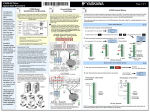
Fig.1 & 2 below show the electrical connections for the
input power and motor terminals for various E7 models.
Select the proper diagram for the model you are installing
(see Step 1). WITH POWER OFF make the appropriate
connections.
Make sure to follow good wiring practices and all
applicable codes. Ensure that the equipment is
grounded properly as shown.
DANGER, LETHAL VOLTAGES ARE PRESENT- Before
Weight
Serial
Number
UL File
Number
This step shows how to connect control wiring to the E7. Before making any control connections MAKE SURE POWER
TO THE E7 IS TURNED OFF! Next remove the terminal cover to gain access to the control terminals (See Step 1).
The E7 is DEFAULT SETUP FOR SPEED COMMAND SIGNAL FROM TERMINALS. Please refer to the diagram
below for wiring an external speed command signal. Program b1-01 to 0 to set speed command from the digital
operator.
For use with 0 – 10V Speed Command Signal
-
B2
+
+1
SN SC SP A1 A2 +V AC
AC
O
F
F2
+2
+
The clearances to be maintained around the enclosure
for adequate ventilation.
The environmental specifications such as avoiding
excessive dampness, extreme temperatures, chemical
exposure, corrosive areas etc. to avoid damage to the
equipment and to maintain safety.
R/L1 S/L2 T/L3
-
+1
B2
B1
+2
U/T1 V/T2 W/T3
+
-
SN SC SP A1 A2 +V AC
(R/L1)
(S/L2)
(T/L3)
(U/T1)
Connect to
chassis
ground
(V/T2)
AC
SN SC SP A1 A2 +V AC
R+ R-
AC
R+ R-
(W/T3)
O
F
F
E(G)
1
2
S1 S2 S3 S4 S5 S6 S7 FM AC AM IG S+ S-
S1 S2 S3 S4 S5 S6 S7 FM AC AM IG S+ S-
Connect to
chassis ground
S1-2 in ON
Position
Cable
Shield
Black: Output
4 – 20mA (2)
Brown or Red: +Power (1)
L1 L2 L3
Connect
frame to
ground
Use L1, L2 for
Use L1, L2, L3 for
1Ø Input Power * 3Ø Input Power
Potentiometer
2K Ohm
3Ø Induction
motor
Note: Only for use with PI Mode
(Refer to TM.E7.01 section 5-17)
Used also used in Hand Mode when b1-12 set to ‘1’
Fig. 1 Input Power and Output Motor Electrical Connections for
Models: 20P4 to 2018 & 40P4 to 4018
b1-02
SELECT RUN COMMAND METHOD
NOT USED
R/L1
S/L2
-
+1
U/T1
T/L3
+2
V/T2
W/T3
Removing and Attaching the Terminal Cover
Improper removal of the E7 terminal cover as well as front
cover can cause extensive damage to the E7. To avoid
damage to these items, please pay particular attention to the
E7 User Manual, Document No. TM.E7.01, Section 1.7,
Removing and Attaching the Terminal Cover.
The E7 is DEFAULT SETUP TO START/STOP FROM TERMINALS. Please refer to the diagram below for wiring an
external run command switch or contact. Program b1-02 to 0 to start/stop the E7 from the digital operator using the
AUTO button.
Use for permanent contacts
2-Wire Control
(Factory Default)
E7 User Control Terminals
E(G)
(R/L1)
(S/L2)
(T/L3)
(U/T1)
E7 User Control Terminals
E(G)
R+ R-
SN SC SP A1 A2 +V AC
*
To change direction of motor
rotation swap any two of the
three motor leads
(See Step 2)
Connect to
chassis
ground
Input
Protection
(Fuse or Circuit
Breaker)
AC
Use for momentary contacts
3-Wire Control
AC
R+ R-
(W/T3)
(V/T2)
*
S1 S2 S3 S4 S5 S6 S7 FM AC AM IG S+ S-
S1 S2 S3 S4 S5 S6 S7 FM AC AM IG S+ SCable
Shield
L1 L2 L3
Connect
frame to
ground
Open Chassis
E7 User Control Terminals
Input
Protection
(Fuse or Circuit
Breaker)
R1/L11 S1/L21 T1/L31
NEMA 1
-
For use with 2-Wire, 4 – 20mA Transducer
O
F
F
To change direction of
motor rotation swap any
two of the three motor
leads (See Step 2)
2
4 – 20mA
E7 User Control Terminals
NOT USED
1
Cable
Shield
For use with Potentiometer
The mounting of the E7 is extremely important regarding
environment and accessibility. Depending on your system,
there are various models available and the mounting
dimensions (footprint) may be different. Because the
mounting procedure is fairly extensive, it is beyond the scope
of this document, the user is referred to the E7 User Manual
(Document No. TM.E7.01) received with the E7, Section 1
Physical Installation. Match the model that you received
and follow the procedure described in the manual to ensure
a safe and functional installation. In cases where the system
has more than one E7, refer to the proper clearances
required for adequate ventilation. Please pay particular
attention to:
S1-2 in ON
Position
S1 S2 S3 S4 S5 S6 S7 FM AC AM IG S+ S-
0 – 10V
Mounting the E7
R+ R-
O
F
F
Cable
Shield
In the case of systems with multiple VFDs follow the
above procedure for each VFD and the motor it will
control.
AC
E(G)
S1 S2 S3 S4 S5 S6 S7 FM AC AM IG S+ S-
Ensure that the output power from the VFD is
compatible with the motor requirements.
YEA Document Number: TM.E7.03 01/15/2010
E7 User Control Terminals
SN SC SP A1 A2 +V AC
R+ R-
E(G)
SN SC SP A1 A2 +V AC
Please read this
cheat sheet and
the E7 User
Manual (TM.E7.01)
provided with
the E7
thoroughly
before
attempting any
installation.
For use with 4 – 20mA Speed Command Signal
E7 User Control Terminals
WARNING DO NOT CONNECT ANY OF THE
FOLLOWING TERMINALS TO EARTH GROUND
B1
b1-01
SELECT SPEED COMMAND METHOD
cover is fastened and all wiring connections are
secure. After the power has been turned OFF, wait at
least five minutes until the charge indicator
extinguishes completely before touching any wiring,
circuit boards or components.
Check that the available power meets the input power
requirements.
E7 Control Wiring
3
! applying power to the E7, ensure that the terminal
Output Power
Rating
Page 1 of 2
Use L1, L2 for
Use L1, L2, L3 for
3Ø Induction
1Ø Input Power * 3Ø Input Power
motor
Fig. 2 Input Power and Output Motor Electrical Connections for
Models: 2022 & Larger and 4030 & Larger
* Make sure the drive has been properly sized for single phase input power.
Connect switch or contact to
terminal S1 and terminal SN
Normally Open
Use for permanent contacts
2-Wire Control
Connect momentary contacts
to terminal S1, S2 and SN
Normally Closed
*
Factory Supplied
©2010 Yaskawa Electric America, Inc. (800) YASKAWA (927-5292)
Fax (847) 887-7310
Cable
Shield
[email protected]
www.yaskawa.com
To use 3-Wire
Control, first
initialize the E7
using parameter
A1-03 = 3330
(Refer to
TM.E7.01)
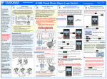
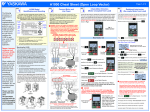
E7 Cheat Sheet
Step
Step
Step
E7 Quick Setup
4
Next, push
2 times on the Digital Operator until the Digital Operator shows the
Quick Setting Menu.
Next press
Check Motor Rotation and Direction
5
This step shows how to set up the most important parameters using the E7 Quick Setup function. Apply power to
the E7 after all the electrical connections have been made and the terminal cover has been re-attached. At this
point DO NOT RUN THE MOTOR. The Digital Operator should be reading as shown in Fig. 3 (See Step 5).
Page 2 of 2
6
Check the motor for proper direction and operation. This test is to be performed
solely from the digital operator. Apply power to the E7 after all the electrical
connections have been made and protective covers have been re-attached. At this
point DO NOT RUN THE MOTOR. The Digital Operator should display as shown
below in Fig. 3.
Hand / Auto Mode Operation
HAND MODE
The E7 can be operated in HAND mode when the following actions have been
performed:
All parameters are programmed
Motor direction is correct
Hand Mode: Hand Reference source selected in parameter b1-12
to start the Quick Setup procedure.
FWD LED
ON
Hand Reference b1-12
01 Flashing
The E7 Quick Setup consists of the most important parameters to setup your E7 Drive for use with your motor system.
Fig. 3 Digital Operator
Press
to access a parameter, and use
to select the digit and use
to change the parameter value.
Press Hand Button
Press
to save the value.
STOP LED ON
Press
Press
Default
Value
then press
to change the speed command.
to exit the Quick Setting menu and go to operation.
Description
Comments
b1-01
1
Speed Command Source
Speed Control Method
0 = Digital Operator (Adjust Motor Speed from keypad)
1 = Terminals (Speed Pot. / 0 - 10V / 4 - 20mA)
b1-02
1
Run Command Source
Start/Stop Control Method
0 = Digital Operator (Start/Stop motor from keypad)
1 = Terminals (Start/Stop using external contact / switch)
b1-03
0
Stop Method Selection
0 = Ramp to stop (Motor ramps down at stop command)
1 = Coast to stop (Motor freewheels at stop command)
b5-01
0
PI Mode Selection
0 = Disabled, 1 = Enabled, 3 = Fref + PI
b5-02
2.0
Proportional Gain Setting
Only active when b5-01 is set to value greater than 0
b5-03
5.0 sec.
Integral Time Setting
Only active when b5-01 is set to value greater than 0
b5-31
0
PI Unit Selection
Predefined Engineering Units, see TM.E7.01
C1-01
30.0 sec.
Acceleration Time
The time it takes to ramp up from 0 to maximum motor speed.
C1-02
30.0 sec.
Deceleration Time
The time it takes to ramp down from maximum motor speed to 0.
d2-01
100.0 %
Frequency Upper Limit
Maximum motor speed allowed (e.g. 100 % = Max rpm)
d2-02
0.0 %
Frequency Lower Limit
Minimum motor speed allowed (e.g. 0 % = Min rpm)
E1-01
*
Input Voltage Setting
Nominal voltage of incoming line
E2-01
*
Motor Rated Current
Motor nameplate current
H3-08
2
Terminal A2 Signal Level Selection
0 = 0 - 10V
2 = 4 - 20mA
3 = 0 - 20mA
H3-09
2
Auxiliary Terminal Input Selection
Predefined signals, see TM.E7.01
H3-13
0
Master Freq. Ref. Terminal Selection
0 = Main Fref is terminal A1
1 = Main Fref is terminal A2
AUTO MODE
0 Flashing
Next press
Quick Setup Parameters
Parameter
Hand Frequency Reference Selection: b1-12
0: Use digital operator to enter Speed command (factory default)
1: Use analog input terminal A1 or A2 depending on parameter H3-13 selection
(See Step 3 for wiring instructions).
to go to the next parameter to continue the Quick Setup programming.
When Quick Setup is completed press
Press to Turn Off/Stop System
then
.
The motor should now be operating at low speed, e.g. 10.00 Hz, running in the
correct forward direction.
Next, press
The E7 can be operated in AUTO mode when the following actions have been
performed:
All parameters are programmed
Motor direction is correct
Auto Mode: Reference source selected in parameter b1-01 (See Step 3)
Auto Mode: Run source selected in parameter b1-02 (See Step 3)
on the Digital Operator.
Set Reference (b1-01)
If motor rotation is not correct, power down the E7 Drive.
!
DANGER
After the power has been turned OFF, wait at least five minutes until the
charge indicator extinguishes completely before touching any wiring, circuit
boards or components.
Press Auto Button
Press to Turn Off/Stop System
YEA Document Number: TM.E7.03 01/15/2010
Digital Operator turned off.
Press the AUTO button to put the E7 into AUTO mode.
Using Safety precaution, and referring to Fig.1 or 2, swap any two of the three
output leads to the motor (U/T1, V/T2 and W/T3). After the wiring change, repeat
Step 3 to recheck motor direction.
©2010 Yaskawa Electric America, Inc. (800) YASKAWA (927-5292)
Fax (847) 887-7310
In AUTO mode the E7 is capable of starting or stopping based on the Run
Command Selection setting parameter b1-02 (See Step 3 Select Run Command
Method).
The Speed Command used in AUTO mode is based on the Speed Command
Selection setting parameter b1-01 (See Step 3 Select Speed Command Method).
[email protected]
www.yaskawa.com