1
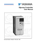
Simplex Cheat Sheet
To make sure you received the correct model, it is
essential to verify the iQpump nameplate with your order
and make sure that the iQpump has the correct rating so it
can be used with your motor. Please check the nameplate
information as shown in the example below.
Model No.
Input Power
Output Power
MODEL: CIMR-P7U2011
Drive Spec.
SPEC: 2011A
INPUT: AC3PH 200-240V 50/60Hz 53A
OUTPUT: AC3PH 0-240 0-120Hz 46.2A 18kVA
Serial No.
Drive FLA
O/N
MASS: 7.0kg
S/N: 1W06Z7123450001
PRG:0032
Weight
FILE: E131457
Step
2
Check that the available power will meet the input
power requirements.
·
Ensure that the output power from the iQpump is
compatible with the pump motor requirements.
In the case of systems with more than one iQpump,
follow the above procedure for each iQpump and pump
motor.
·
Mounting the iQpump
The mounting of the iQpump is extremely important
regarding environment and accessibility. Depending on your
system, there are various models available and the mounting
dimensions (footprint) may be different. Because the
mounting procedure is fairly extensive, it is beyond the scope
of this document; the user is referred to the iQpump User
Manual (Document No. TM.iQp.01) received with the
iQpump, Section 1 Physical Installation. Match the model
that you received and follow the procedure described in the
manual to ensure a safe and functional installation. In cases
where the system has more than one iQpump, refer to the
proper clearances required for adequate ventilation. Please
pay particular attention to:
·
The clearances to be maintained around the enclosure
for adequate ventilation.
·
The environmental specifications, such as avoiding
excessive dampness, extreme temperatures, chemical
exposure, corrosive areas, etc., to avoid damage to the
equipment and to maintain safety.
DANGER, LETHAL VOLTAGES ARE PRESENT- Before
The iQpump is DEFAULT SETUP TO START/STOP FROM THE
KEYPAD (digital operator). If this is the preferred start/stop
method, then continue to the feedback signal connection section.
Please refer to the wiring diagram below to start/stop the iQpump
using an external switch or contact.
! applying power to the iQpump, ensure that the
terminal cover is fastened and all wiring connections
are secure. After the power has been turned OFF, wait
at least five minutes until the charge indicator
extinguishes completely before touching any wiring,
circuit boards or components.
B1
-
B2
+
+1
SELECT START / STOP CONTROL METHOD
Pump Quick Setup
In this step, the iQpump is set up for a simplex pump
application using the pump quick setup menu. Apply power
to the iQpump after all the electrical connections have
been made and the terminal cover has been reattached. At
this point DO NOT RUN THE MOTOR; the digital operator
should be reading as shown below in Fig. 3.
FWD LED
ON
iQpump User Control Terminals
SN SC SP A1 A2 +V AC
WARNING, DO NOT CONNECT ANY OF THE
FOLLOWING TERMINALS TO EARTH GROUND
AC
01 Flashing
R+ R-
E(G)
+2
Feedback
Value
S1 S2 S3 S4 S5 S6 S7 FM AC AM IG S+ SCable
Shield
Connect switch or contact to
terminal S1 and terminal SC
Use for permanent contacts
2-Wire Control
R/L1 S/L2 T/L3
-
+1
B2
B1
+2
U/T1 V/T2 W/T3
NOT USED
E(G)
SN SC SP A1 A2 +V AC
AC
R+ R-
STOP LED OFF
Fig. 3 Digital Operator
(R/L1)
(S/L2)
(T/L3)
(U/T1)
Connect to
chassis
ground
(V/T2)
(W/T3)
S1 S2 S3 S4 S5 S6 S7 FM AC AM IG S+ STo change direction of
motor rotation swap any
two of the three motor
leads (see Step 2).
Connect to
chassis ground
Normally Open
Input
Protection
(Fuse or Circuit
Breaker)
Connect momentary contacts
to terminal S1, S2 and SC
L1 L2 L3
Connect
frame to
ground
Use L1, L2 for
Use L1, L2, L3 for
1Ø Input Power * 3Ø Input Power
3Ø Induction
motor
R/L1
S/L2
W/T3
SN SC SP A1 A2 +V AC
Cable
Type
AC
S1-2 in ON
Position
R+ R-
O
F
F
S1 S2 S3 S4 S5 S6 S7 FM AC AM IG S+ S-
(T/L3)
(U/T1)
Next press
1
DATA
Press
ENTER
NEMA 1
to select the digit and use
Black: Output
4 – 20mA (2)
E(G)
SN SC SP A1 A2 +V AC
Cable
Shield
L1 L2 L3
Open Chassis
>
RESET
to change the
parameter value.
Brown or Red: +Power (1)
AC
R+ R-
S1-2 in OFF
Position
S1 S2 S3 S4 S5 S6 S7 FM AC AM IG S+ S-
Connect
frame to
ground
to start
For use with 2-Wire, 4 – 20mA Transducer (Factory Default)
(W/T3)
To change direction of pump
motor rotation swap any two
of the three motor leads
(see Step 2).
Connect to
chassis
ground
to access a parameter, use
2
(V/T2)
Input
Protection
(Fuse or Circuit
Breaker)
DATA
ENTER
Cable
Shield
DIN
Type
(S/L2)
the Digital Operator shows the Pump Quick Setup Menu.
The Pump Quick Start Menu consists of the most important
parameters to set up your iQpump Drive for use with your pump
system.
E(G)
Improper removal of the iQpump terminal cover as well as
front cover can cause extensive damage to the iQpump. To
avoid damage to these items, please pay particular attention
to the iQpump User Manual, Document No. TM.iQp.01,
Section 1.8, Removing and Attaching the Terminal Cover.
2 times on the Digital Operator until
FEEDBACK SIGNAL WIRING (TRANSDUCER)
+2
V/T2
MENU
the Pump Quick Setup procedure.
iQpump User Control Terminals
+1
U/T1
T/L3
To use 3-Wire Control first
initialize the iQpump using
parameter A1-03 = 3330
(Refer to the TM.iQp.01)
Use for momentary contacts
3-Wire Control
Cable
Shield
NOT USED
-
Next, push
Normally Closed
Fig. 1 Input Power and Output Motor Electrical Connections for
Models: 20P4 to 2018 & 40P4 to 4018
(R/L1)
Please read this
cheat sheet and
other
documentation
provided with
the iQpump
thoroughly
before
attempting any
installation.
4
Control Wiring
This step shows how to connect control wiring and feedback signal
to the iQpump. Before making any control connections, MAKE
SURE POWER TO THE iQpump IS TURNED OFF! Next remove
the terminal cover to gain access to the control terminals (Step 1).
R1/L11 S1/L21 T1/L31
Removing and Attaching the Terminal Cover
3
Step
Fig. 1 & 2 below show the electrical connections for the
input power and motor terminals for various iQpump
models. Select the proper diagram for the model you are
installing (see Step 1). WITH POWER OFF make the
appropriate connections.
Make sure to follow good wiring practices and all
applicable codes. Ensure that the equipment is
grounded properly as shown.
UL File No.
·
Step
Connect Pump Motor and
Line Power
>
When installing
the system, be
sure to follow
good wiring
practices and all
applicable codes.
Ensure that the
mounting of the
various
components are
secure and that
the environment,
such as extreme
dampness, poor
ventilation, etc.,
will not cause
system
degradation.
1
iQpump Model Identification
and Mounting
>
Danger:
Improper wiring
can and will
cause bodily
harm as well as
damage to the
equipment.
Step
Use L1, L2 for
Use L1, L2, L3 for
3Ø Induction
1Ø Input Power * 3Ø Input Power
motor
Fig. 2 Input Power and Output Motor Electrical Connections for
Models: 2022 & Larger and 4030 & Larger
* Make sure the drive has been properly sized for single phase input power.
Black or White Output
0 – 10V (3)
Blue or Black
Common Signal (2)
Brown or Red: +Power (1)
For use with 3-Wire, 0 – 10V Transducer
!
Important Note: Signal colors and numbering may
vary depending on feedback device used, please
consult feedback device manual.
O
F
F
1
2
Press
DATA
ENTER
to save the value.
IMPORTANT: Enter service factor amps (SFA) when using an
iQpump in combination with submersible motor.
Press
>
The following
procedure is a
supplement to
other
documentation
supplied with this
equipment and
will guide the user
in properly wiring
the iQpump and
motor. It will also
show the user
how to configure
the iQpump for a
simplex pump
application.
Page 1 of 4
to go to the next parameter to continue the Pump
Quick Setup programming. When Quick Setup is completed, press
MONITOR
to exit the Pump Quick Setup menu and go to operation.
Note: Refer to Step 5 for a Pump Quick Setup
Parameter Overview.
Simplex Cheat Sheet
Step
5
iQpump Quick Setup Parameter Overview (Simplex)
E2-01
Drive Size
Dependent
E2-04
2
Description
Motor Rated Current
Number of Motor Poles
Reference
Set to the motor nameplate full load amps.
Number of motor poles is used to show the correct motor RPM on the display
Enter „4‟ for an 1800 RPM motor and „2‟ for a 3600 RPM motor.
Selects how the pump system is started:
0
(Keypad)
Run Command Selection
0: Operator - “Hand” and “Off” keys on digital operator
1: Terminals - Contact Closure on Terminal S1
b1-01
0
(Keypad)
Frequency Reference Selection
P1-02
PSI
System Units
P1-03
145
Feedback Device Scaling
b5-12
0
(Disabled)
PI Feedback Ref Missing Detection Selection
0%
PI Feedback Loss Detection Level
P1-04
1.0 sec.
0.0 PSI
PI Feedback Loss Detection Time
Start Level
Confirm number of poles
Only change if Start/Stop command is
NOT from keypad.
Only change if System Set-Point is NOT
0: Operator - Enter set-point on Keypad (Operator)
set via the keypad (see U1-01
1: Terminals - Set-point from external analog signal
Parameter).
System Scaling: Select pump system units:
Confirm system units.
Example: For a constant pressure system select PSI, for constant flow system select GPM.
(See illustration 1)
System Scaling: Enter feedback device maximum:
Confirm feedback device scaling.
Example: Enter 200 for pressure transducer with a maximum of 200 PSI at 20mA.
(See illustration 1)
Select what to do when the feedback device (transducer) fails or gets disconnected.
Also known as transducer loss
0: Disabled, continue running no message is displayed
detection. Not recommended to set on
1: Alarm, show warning on the keypad when the feedback device fails or is disconnected
initial startup until system is operating
2: Fault, stop pump system when the feedback fails or is disconnected
properly.
Example: Maximum feedback level (P1-03) set to 200 PSI. Enter 5% to indicate that a pressure below 10
PSI indicates that the feedback device has failed or has been disconnected. (10 PSI ÷ 200 PSI = 5%)
b5-14
For submersible motors use service
factor (SF) amps.
Selects how to set the system set-point:
Level in percentage feedback to indicate feedback device has failed or is disconnected.
b5-13
Comments
Refer to iQpump User Manual
(Document No. TM.iQp.01)
Delay time before iQpump shows alarm or fault when feedback device has failed or is disconnected.
1
SYSTEM FEEDBACK UNIT / FEEDBACK DEVICE SCALING
P1-02 Feedback Unit
P1-03 = 0 0 0 0 0 Feedback Scaling
0: Inch or Water
1: PSI
2: GPM
3: Degrees Fahrenheit
4: CFM
5: CMH
6: Liters
2
system will start after the time specified in P1-05.
in order to use the sleep
Example: Start Level P1-04 set to 50 PSI and delay time P1-05 set to 5 sec. Pump system will start when
function.
the pressure drops below 50 PSI for 5 sec.
(See illustration 2 and 3)
0
3
0 Sec
Start Level Delay Time
Start delay time before pump system starts when feedback signal level falls below the start level (P1-04)
greater based on your system
requirements.
P2-01
0
(Frequency)
Sleep Level Type
0: Output Frequency, iQpump checks output frequency (motor speed)
1: Output Current, iQpump checks motor current
2: Feedback Signal, iQpump checks feedback level signal
P2-02
P2-03
P1-06
0.0 Hz
10 sec.
35.0 Hz
Sleep Level
Sleep Delay Time
Minimum Pump Frequency
When the selected signal level (P2-01) falls below the sleep level (P2-02) the system will stop and go to
sleep. Example: Sleep level at 35 Hz indicates (2100 ÷ 3600 x 60 Hz = 35 Hz) that the pump system will
stop running when the pump motor speed is smaller or equal to 2100 RPM for the sleep delay time
specified (P2-03).
Time it takes before the pump system goes to sleep when the selected signal level (P2-01) falls below
the specified sleep level (P2-02)
(e.g. closed valve).
(See illustration 3)
For the sleep function to become active
the motor speed (frequency) has to rise
above P2-02 first and then drop back
Minimum speed (Hz) the pump motor has to operate at.
P1-06 should be set to 1 Hz below P2-02
Example: Base pump motor speed is 3600 RPM, minimum speed is 1800 RPM. Set minimum pump
level after sleep function has been tested.
frequency to 30.0 Hz (1800 ÷ 3600 x 60 Hz = 30 Hz).
For initial startup set P1-06 to 35 Hz.
Time it takes to accelerate the pump motor from zero to maximum speed.
C1-02
25.0 sec.
Deceleration Time 1
Time it takes to decelerate the pump motor from maximum speed to zero.
Recommended to program to 10.0 sec.
for initial startup but might have to be
adjusted depending on system
performance.
Specifies source to set hand mode operation speed.
Only change if Hand Reference is NOT
P5-01
1
(Keypad)
0: External Analog Signal (0 to 10V)
set via the keypad. (See parameter
1: Keypad, use parameter P5-02 to set hand mode speed
P5-02 and illustration 4)
Recommended initial setting of 45.0 Hz. It
Hand Reference
Sleep Mode (P2-01)
(Example 0 - Output Frequency)
Sleep Level P2-02
(Example 35.0 Hz)
Minimum Speed P1-06
(Example 30.0 Hz)
Ramp or Coast to Stop, B1-02
Pump Running
Go to Sleep
WAIT FOR PRESSURE TO FALL BELOW
START LEVEL (P1-04)
NOTE: Sleep Level (P2-01) must be set to a value greater than minimum speed level (P1-06)
4
HAND MODE OPERATION
Hand Speed from the Keypad/Digital Operator (Default)
Press the HAND KEY on the digital operator to run the system in Hand Mode.
Hand Mode speed can be adjusted with parameter P5-02 „Hand Reference‟
available in the Pump Quick Setup (recommended setting is 45.0 Hz for
initial startup).
down below P2-02.
Acceleration Time 1
0.0 Hz
Start Level P1-04
(Example 100 PSI)
System Units (P1-02)
(Example PSI)
Feedback Scaling (P1-03)
(Example 200 PSI)
Time
that sleep function is working properly.
system detects a no-flow condition
SYSTEM STARTS WHEN
PRESSURE SIGNAL
FALLS BELOW 100 PSI
SYSTEM GOES TO SLEEP
WHEN PUMP MOTOR SPEED
DROPS BELOW 2100 RPM
Output
Sleep Delay Time (P2-03)
Frequency
(Example 10.0 sec.)
(pump motor
speed)
0
Note: confirm during startup of iQpump
25.0 sec.
P5-02
Start Pump System
initial startup.
C1-01
Hand Mode Reference Source
Start
Delay
SLEEP MODE (Example)
Recommended setting of 45.0 Hz for
The iQpump should go to sleep when the
0 – 300.0, one decimal, P1-03 = 10300
0 – 50.00, two decimals, P1-03 = 25000
Decimal Point
Position
Time
(See illustration 2 and 3)
Make system go to sleep when the selected signal level falls below sleep level (P2-02)
0 – 1000, no decimals, P1-03 = 1000
System Set-Point
(Example 150 PSI)
WAIT
Recommended setting of one second or
P1-05
Feedback
Maximum
Feedback Signal from
pressure transducer
(4 – 20 mA)
200 PSI Start Level Delay (P1-05)
(Example 5.0 sec.)
Example: 5.0 sec., iQpump displays alarm or fault 5 sec. after the device has failed or is disconnected.
It is mandatory to program the start level
Examples:
START LEVEL (Example)
60 Hz
When the iQpump is turned On and the feedback signal level (transducer) falls below this level the pump
7: Liters/Sec
8: Bar
9: Pascal
10: Degrees Celsius
11: Meters
12: Percent
Pressure
Value
Output Frequency
Parameter
b1-02
Page 2 of 4
Specifies speed the pump system will operate at in hand mode operation when hand mode reference
is mandatory to program hand reference
parameter P5-01 is set to „1‟.
in order to use the hand mode operation.
(See illustration 4)
Hand Speed from Analog Input (0 – 10V)
Set parameter P5-01 „Hand Mode Ref.‟ to „0‟ to adjust the hand mode
reference from an external 0 – 10V signal connected to terminal A1 and SC.
SN SC SP A1 A2 +V AC
AC
R+ R-
S1 S2 S3 S4 S5 S6 S7 FM AC AM IG S+ S-
-
+
0 – 10V
HAND KEY
Simplex Cheat Sheet
Step
iQpump Quick Setup Parameter Overview (Simplex) continued
P1-14
0.0 A
P4-09
0.2 min
L5-01
0
L5-03
P4-08
180 sec.
0
Not Maintaining Set-Point Delay Time
Delay time before „Not Maintaining Set-point‟ fault occurs based on the maximum set-point difference specified in
parameter (P1-11)
Prime Loss Level
Used to detect loss of prime in the pump. If output current drops below this level for the time specified in P1-12
and the output frequency is at maximum frequency, a “Loss of Prime” fault occurs. The iQpump will coast to stop
when a fault occurs.
Loss of Prime Maximum
Restart Time After Fault
If the restart fails (or is not attempted due to a continuing fault condition) the iQpump waits this many minutes
before attempting another restart. Note: This parameter will take the place of L5-03 during a Loss of Prime Fault
restart attempt.
Number of Auto Restart Attempts
Determines the number of times the iQpump will perform an automatic restart.
Maximum Restart Time After Fault
If the restart fails (or is not attempted due to a continuing fault condition, e.g. an OV fault) the iQpump waits the
Maximum Restart Time After Fault (L5-03) before attempting another restart. This parameter is not applicable to
Loss of Prime Fault.
Protection Fault Auto Restart Enable
Parameter used to enable/disable Auto Restart for the following iQpump protection faults (N = disable/Y = enable):
SP: Not Maintaining Set-Point (P1-11), LOP: Loss of Prime (P1-12), POC: Pump Over Cycling (P2-08))
Note: Parameter L5-02 needs to be set to „1‟ and program L5-03 needs to be set to the applicable time.
P4-07
0
Feedback Fault Auto Restart Enable
Setting to enable/disable Auto Restart for the following iQpump transducer/feedback faults (N = disable/Y =
enable): LL: Low Level Feedback (P1-07), HL: High Level Feedback (P1-09), TL: Transducer Loss (b5-12)
Not recommended to set on initial
startup until system is operating
properly and not maintaining set-point
is required for system protection.
(See illustration 1)
Not recommended to set on initial
startup until system is operating
P1-08
P1-09
P1-10
P2-10
P4-01
P4-02
P4-03
P4-04
P4-05
P4-06
P4-10
0.0 PSI
5 sec.
155 PSI
2 sec.
0.0 PSI
0.0 PSI
0.0 Hz
0.0 min.
1.0 sec.
0.0 Hz
1.0 sec
0
Disabled
Low Feedback Level
Low Feedback Level Fault Delay Time
High Feedback Level
High Feedback Level Fault Delay Time
Maximum Set-Point Compensation
Pre-Charge Level
Pre-Charge Frequency
P1-11
Set-point-LOP Tim
Not recommended to set on initial
startup until system is operating
properly and automatic restarts on
iQpump & pump faults are required
for system protection.
Refer to iQpump User Manual
(Document No. TM.iQp.01)
2
LOW/HIGH FEEDBACK LEVEL DETECTION
iQpump continuously monitors the system feedback signal. To display a „Low Feedback‟ fault set the low feedback
level parameter P1-07 to the minimum feedback level allowed for your system and to display a „High Feedback‟
fault set the high feedback level parameter P1-09 to the maximum feedback level allowed.
3
PRE-CHARGE OPERATION
This function is used when the pump system requires to be pre-charged before normal operation. Upon start, the
iQpump will run at a fixed speed for a specified time or until the feedback signal reaches a programmed level, after
which it will switch to auto mode operation.
Feedback
Pre-Charge Completed
programmed level for a time specified in P1-08. The iQpump will coast to a stop when a fault occurs. A value of 0
startup until system is operating
disables this function. This function is only active during running while operating in the auto mode.
properly and low/high feedback is
Pre-Charge Freq. P4-02
required for system protection.
Sets the frequency reference used when the pre-charge function is active.
Sets the maximum allowed pre-charge time. A value of 0 disables this function.
Thrust Bearing Acceleration Time
Sets the thrust bearing acceleration time. When enabled (P4-05>0), the iQpump output frequency will ramp up to
the specified thrust bearing frequency reference in P4-05 using an acceleration time as specified in P4-04. The PI
mode is automatically disabled. Once the output frequency reaches the programmed thrust bearing frequency, the
iQpump automatically switches to PI control and the original acceleration time (C1-01), and will continue in the
normal operation (auto) mode, unless Pre-Charge is enabled, in which case Pre-Charge mode occurs. This
function active in the Hand Mode and Auto Mode.
Note: In Auto Mode, the Minimum Pump Frequency (P1-06) will become the thrust bearing frequency if smaller
than the thrust bearing frequency in P4-05. In Hand Mode, the minimum frequency is P4-05 when the thrust mode
is enabled. The Pre-Charge level is not active in the Hand Mode.
Thrust Bearing Frequency
Sets the frequency reference used when the thrust bearing function is active. A value of 0 disables this function.
Thrust Bearing Deceleration Time
This deceleration time will be used to bring the iQpump from Thrust Frequency (P4-05) to stop when Thrust Mode
is active. Any time the Run Command is removed while the iQpump is operating in the Thrust Mode above the
Thrust Frequency, this deceleration time will be used once the frequency reference is at or below the Thrust
Frequency. Note: In Auto Mode, the Minimum Pump Frequency (P1-06) will become the thrust bearing frequency
if smaller than the thrust bearing frequency in P4-05. In Hand Mode, the minimum frequency is P4-05 when the
thrust mode is enabled. The Pre-Charge level is not active in the Hand Mode.
Stores the run status in the Auto mode when operating from digital operator (b1-02=0).
0: Disabled
1: Enabled
Do not program unless pump
over-cycle function is used.
Refer to iQpump User Manual
(Document No. TM.iQp.01)
Not recommended to set on initial
(See illustration 3)
Refer to iQpump User Manual
(Document No. TM.iQp.01)
IMPORTANT PLEASE READ
Auto Operation
P4-01 Pre-Charge Level: Specified feedback level to stop pre-charge operation
P4-02 Pre-Charge Frequency: Set desired pre-charge speed
P4-03 Pre-Charge Time: Specified maximum pre-charge operation time
4
THRUST BEARING - SUBMERSIBLE MOTORS (e.g. Franklin)
When using a submersible motor in combination with the iQpump, it is recommended to use the Thrust Bearing
function to prevent excess motor wear. To enable this function, enter the minimum motor frequency in parameter
P4-05. Example: Minimum motor speed 1800 RPM, 1800 RPM ÷ 3600 RPM x 60.0 Hz = 30.0 Hz
Turn Off Thrust Bearing Function
(Output Frequency Reached)
startup until system is operating
properly.
Output
Frequency
0 Hz
(See illustration 2)
The iQpump will initiate a “High Feedback Fault (HFB)” when the feedback level rises above the programmed
level for a time specified in P1-10. The iQpump will coast to a stop when a fault occurs. This function is active
during running in all operation modes.
Sets the level when the iQpump will run at the pre-charge frequency (P4-02). The iQpump will stop when one of
the following conditions occurs: Feedback signal rises above P4-01 level, pre-charge timer P4-03 expires, or low
water digital input is deactivated (H1-XX = 85). The pre-charge function can only be activated while in a stop
condition. The function is enabled by setting P4-03 to a value greater than 0. When the function is activated, the
iQpump operator display indicates a “Pre-charge” alarm. Note: This function is only active in the stopped mode.
Thrust Mode: The pre-charge level is used when the thrust mode is active for the feedback check. The thrust
mode is deactivated when the feedback exceeds the programmed level in P4-01. A value of 0 disables the thrust
mode feedback check function.
SET-POINT NOT MET
Time
Pre-Charge Lvl. P4-01
Not recommended to set on initial
Maximum allowable set-point compensation for the over-cycling function.
P1-12
SET-POINT
Refer to iQpump User Manual
(Document No. TM.iQp.01)
The iQpump will display a “Low Feedback/Water (LFB/LW)” alarm when the feedback level falls below the
Pre-Charge Time
Auto Mode Operator Run Power Down
Storage
The iQpump can display a „Set-point Not Met‟ fault when the iQpump is unable to maintain the programmed system
set-point due a problem with the pump system. Set P1-11 to the maximum allowed difference between set-point and
feedback level.
FEEDBACK SIGNAL
P1-11
P1-11 Max Set-point Diff
is required for system protection.
The iQpump will display a “Low Feedback (LFB)” alarm when the feedback level falls below the programmed
level. The alarm will turn off when the feedback level rises above the programmed Low Feedback Level plus the
Hysteresis Level (P1-13). A value of 0 disables this function. This function is only active during running while
operating in the auto mode.
The iQpump will display a “High Feedback Level (HFB)” alarm when the feedback level rises above the programmed level. The alarm will turn off when the feedback level falls below the programmed High Feedback Level
minus the Hysteresis Level (P1-13). This function is active during running in the Hand Mode.
PUMP SYSTEM FAULT SETUP
properly and loss of prime detection
Note: Parameter L5-02 needs to be set to „1‟ and program L5-03 needs to be set to the applicable time.
P1-07
1
Thrust Acceleration Time P4-04
(Example 1.0 sec.)
C1-01 Acceleration Time
e
60 sec.
The pump system will stop and show a fault on the display when the difference between the feedback signal level
and the specified set-point exceeds this level for the time specified in parameter P1-12. Example: 30 PSI
difference, set-point 100 PSI, measured is 65 PSI due to a broken pipe in the system.
Comments
Thrust Bearing Frequency P4-05
(Example 30.0 Hz)
el
.T
im
P1-12
Maximum Set-Point Difference
Reference
Ac
c
0.0 PSI
Description
P4
-0
4
P1-11
Value
Output Frequency
5
Parameter
Page 3 of 4
Output Frequency
It is mandatory to program thrust
bearing frequency (P4-05) for all
submersible motors.
Thrust
Bearing
Recommended thrust bearing
frequency is 30.0 Hz and thrust
Auto/Hand Operation
Time
bearing acceleration and deceleration
time is 1.0 sec.
(See illustration 4)
5
AUTO OPERATION – POWER DOWN STORAGE
Allows iQpump to automatically start after power failure when operated from keypad/digital operator. This function is
recommended for use when operating the iQpump in remote/unmanned areas.
Recommended for use when Start/Stop
command is from keypad.
(See illustration 5)
When the iQpump is powered down while running, an internal run
command will automatically be initiated upon power-up.
Simplex Cheat Sheet
Pump Rotation and Feedback Signal Check
6
When Quick Setup is completed, press
MONITOR
to exit the Pump Quick Setup menu
and go to operation.
In this step, the pump motor is checked for proper direction and operation. This test is to
be performed solely from the digital operator. Apply power to the iQpump after all the
electrical connections have been made and the terminal cover has been reattached. At
this point, DO NOT RUN THE MOTOR, the Digital Operator should display as shown
below in Fig. 5.
Step
Auto Mode Operation
7
iQpump can be operated in automatic mode when the following actions have been
performed:
· All parameters are programmed
· Pump motor direction has been checked
· Feedback signal has been checked
At this point, DO NOT RUN THE MOTOR, the Digital Operator should display as shown
below in Fig. 6.
Hand Mode speed can be adjusted with parameter P5-02 ‘Hand Reference’
in the Pump Quick Setup (recommended setting is 45.0 Hz for initial
startup).
After the system has been in operation, confirm that the sleep function operates
satisfactory by closing off the discharge valve. The motor speed
(U1-02) will decrease and the iQpump will go to sleep when U1-02 falls below the
sleep level (P2-02) for the sleep time specified (P2-03).
If iQpump does not go to sleep after the valve has been closed, check U1-02 to
determine the no-flow speed (Hz) and adjust the sleep level (P2-02) to ensure
the motor speed drops below this level. It is recommended to set the sleep level
(P2-02) 2 Hz above the no-flow speed (Hz). After confirmation that the sleep and
wake up function operate correctly, set the minimum pump frequency
(P1-06) to 1 Hz below the sleep level (P2-02).
Refer to iQpump User Manual (Document No. TM.iQp.01)
FWD LED
ON
FWD LED
ON
Output Frequency
Step
Page 4 of 4
01 Flashing
01 Flashing
Fig. 5 Digital Operator
Fig. 6 Digital Operator
60
Hz
Output Sleep Delay Time
Frequency
(P2-03)
(Pump Motor
Speed)
Sleep Mode (P2-01)
(Example 0 - Output Frequency)
Sleep Level P2-02
Minimum Speed P1-06
0
Pump Running
Go to Sleep
Time
NOTE: Sleep Level (P2-01) must be set to a value greater than minimum speed level (P1-06).
TYPICAL DISPLAY MESSAGES
STOP LED OFF
STOP LED OFF
on the Digital Operator; the display should read
HAND
RUN
LED should be ON.
Next, press
Use
>
RESET
DATA
ENTER
to access or modify the system set-point.
to select the digit and
(Example 80 PSI). Next, press
The motor should now be operating at low speed in the correct direction of pump.
Push
DATA
ENTER
>
and the
SET SYSTEM SET-POINT
>
Next, push
Displays when the iQpump is about to
start. The feedback level has fallen below
the Start Level (P1-04) and the start delay
timer is active. Once the Start Level delay
Time (P1-05) expires the iQpump will start.
Displays when the iQpump is in “sleep”
mode or when the iQpump is waiting for
the feedback level to drop below the Start
Level (P1-04).
Displays when “Pre-Charge” mode is
active. Refer to iQpump User Manual
(Document No. TM.iQp.01)
Displays when “Thrust Bearing” mode is
active. To enable, enter value in parameter
P4-05.
The feedback level has dropped below
P1-07 for the time specified in P1-08 or
Low Water input is active. Low
feedback fault is active in Auto Mode
when the iQpump is running.
The feedback level has risen above P1-09
level for the time specified in P1-10. High
feedback fault is active in Hand Mode,
Auto Mode, Pre-Charge and Thrust Mode
when the iQpump is running.
to change the system set-point
to store set-point and press
MONITOR
to return to
the main operation menu.
on the Digital Operator; the display should read as in Fig. 3.
OFF
Next, press the AUTO
button to start the
iQpump.
If the direction is not correct, then power down the iQpump.
! DANGER, LETHAL VOLTAGES ARE PRESENT- Before applying power to the
iQpump, ensure that the terminal cover is fastened and all wiring connections
are secure. After the power has been turned OFF, wait at least five minutes until
the charge indicator extinguishes completely before touching any wiring, circuit
boards or components.
Using Safety precaution, and referring to Fig. 1 or 2, swap any two of the three output
leads to the motor (U/T1, V/T2 and W/T3). After the wiring change, repeat Step 6 and
recheck motor direction.
iQpump automatically starts in Auto Mode when the feedback signal level falls below
the programmed level in parameter P1-04 for the specified time in P1-05.
FEEDBACK SIGNAL CHECK
145 PSI Start Level Delay (P1-05)
(Example 5.0 sec.)
Refer to parameter P1-02 and P1-03, if the feedback
device scaling or system units are incorrect.
Pressure
Verify feedback on display (show keypad) matches mechanical pressure gauge.
System Set-Point
(Example 80 PSI)
Start Level P1-04
(Example 50 PSI)
WAIT
0
FEEDBACK SIGNAL LEVEL
Feedback signal from
pressure transducer
(4 – 20 mA)
Start
Delay
Start Pump System
Yaskawa Electric America, Inc.
2121 Norman Drive South
Waukegan, IL 60085
(800) YASKAWA (927-5292) / Fax (847) 887-7310
[email protected]
www.yaskawa.com
YEA Document Number: TM.iQp.03 7/1/2008
© Yaskawa Electric America, Inc.