1
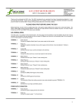
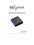
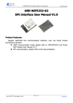
G203V STEPPER DRIVE
REV 7: January 7, 2010
Thank you for purchasing the G203V drive. The G203V is Geckodrive’s new generation CPLD-based microstep drive. It has
short-circuit protection for the motor outputs, over-voltage and under-voltage protection, over-temperature protection, reversed
power supply polarity protection and will survive accidental motor disconnects while powered-up. The “V” in G203V stands for
“Vampire” as it is an unkillable drive.
The G203V uses a synchronous PWM design that is absolutely silent when the motor is stopped or turning slowly. It virtually
eliminates stopped-motor heating regardless of power supply voltage. The G203V is a jumper-free drive. There are no internal
user settings at all so there is no need to ever remove the drive cover at all.
The STEP, DIRECTION and DISABLE inputs are opto-isolated. All three inputs work with 2.5V, 3.3V or 5V logic drive signals.
The input drive current is now 2.5mA at 2.5V so almost all logic family (74LS, 74HC, etc.) can be used to drive these inputs. The
COMMON return for the signals is controller ground referenced instead of +5VDC. This greatly eases the drive to controller
interface.
There are no unusual STEP to DIRECTION timing restrictions. Stepping occurs on the positive edge of the STEP pulse. The
DIRECTION input must be true 200nS before and after this STEP pulse edge.
The G203V microstep drive is warranted to be free of manufacturing defects for 1 year from the date of purchase. Anyone who is
dissatisfied with it or is unable to make it work to their satisfaction for any reason will be cheerfully refunded the purchase price if
the G203V is returned within 15 days of the purchase date in a cosmetically and electrically undamaged condition.
PLEASE READ FIRST BEFORE USING THE G203V
Before you start you must have a 2-phase hybrid PM step motor (ordinary 1.8 or 0.9 degree per step motor), a DC power supply
suitable for the motor and a current set resistor. The motor’s rated phase current must not be more than 7 Amps. The power
supply voltage must be between 15VDC and 80VDC unregulated. The current set resistor may be a 1/4-Watt, 5% part. Finally
have a STEP, DIRECTION and DISABLE (if needed) source available.
G203V TERMINAL WIRING
The G203V uses a 2-piece modular main connector. The connector is split in two pieces; terminals 1 through 6 (power supply and
motor leads) and terminals 7 through 12 (control interface). Each can be removed separately by pulling the connector body
upwards and off of the mating header pins on the G203V. The connectors must initially be removed to mount the G203V to a
heatsink or chassis.
TERMINAL 1
Power Ground
Connect the negative (black) lead of your power supply to this terminal.
TERMINAL 2
Power (+)
Connect the positive (red) lead of your power supply to this terminal. It must be between +18VDC to
+80VDC.
TERMINAL 3
Motor Phase A
Connect one end of your “Phase A” motor winding here.
TERMINAL 4
Motor Phase /A
Connect the other end of your “Phase A” motor winding here.
TERMINAL 5
Motor Phase B
Connect one end of your “Phase B” motor winding here.
TERMINAL 6
Motor Phase /B
Connect the other end of your “Phase B” motor winding here.
TERMINAL 7
Disable
This terminal will force the winding currents to zero when tied to the step and direction controller +5V.
TERMINAL 8
Direction
Connect the DIRECTION signal to this terminal.
TERMINAL 9
Step
Connect the STEP signal to this terminal.
TERMINAL 10
Common
G203V STEPPER DRIVE
REV 7: January 7, 2010
Connect the controller’s GROUND to this terminal.
TERMINAL 11
Current Set
Connect one end of your current set resistor to this terminal.
TERMINAL 12
Current Set
Connect the other end of your current set resistor to this terminal.
POWER SUPPLY WIRING
TERMINAL 1
Power Ground
Connect the power supply ground to term.1
TERMINAL 2
Power (+)
Connect the power supply “+” to this terminal
The power supply voltage must be between 15 VDC and 80 VDC. The maximum power supply current required is equal to the
motor’s rated phase current. An unregulated power supply may be used so long as the voltage stays between the specified limits;
keep the power supply ripple voltage to 10% or less for best results.
CAUTION! Power supply voltage in excess of 80 VDC will blow the G203V internal fuse.
CAUTION! Reversed power supply polarity will blow the G203V internal fuse.
CAUTION! Never put a switch on the DC side of the power supply! This will damage, if not destroy, your drive!
The choice of power supply voltage depends on the required high-speed performance from the motor; doubling the voltage
doubles the motor’s high-speed power. In all cases the power supply voltage should be no less than 4 times or no more than 20
times the motor’s rated voltage. The motor may not run as smoothly as possible if the power supply voltage is less than 4 times or
more than 20 times the motor’s rated voltage. A power supply voltage greater than 20 times the motor’s rated voltage may
overheat and damage the motor. Motor winding inductance should be 500uH or greater.
A more accurate calculation of power supply voltage is to find your motor’s inductance, and put it into the following equation.
32 * (√mH inductance) = Power Supply Voltage
If your motor has 2mH of inductance, the equation would look as follows.
32 * (√2) = 45.12V
MOTOR CONNECTION
TERMINAL 3
Phase A
Connect one motor winding to this terminal
TERMINAL 4
Phase /A
Connect the other end of the winding to this terminal
TERMINAL 5
Phase B
Connect the other motor winding to this terminal
TERMINAL 6
Phase /B
Connect the other end of the winding to this terminal
One motor winding connects to terminals 3 and 4 and the other winding connects to terminals 5 and 6. Turn the power supply off
when connecting or disconnecting the motor. If the motor turns in the wrong direction, reverse the motor winding connections to
terminals 3 and 4.
CAUTION! Avoid shorting the motor leads to each other or to ground or the G203V will enter protective shut-down.
4-wire, 6-wire and 8-wire motor may be used. If 6-wire motors are used, they may be connected in half winding or full winding.
This is equivalent to an 8-wire motor connected in parallel or series. If a motor is connected in series or full winding, the motor’s
G203V STEPPER DRIVE
REV 7: January 7, 2010
phase current rating is half of its parallel or unipolar rating. The choice depends on the high-speed performance required; a
parallel-connected motor will provide twice the power of a series-connected motor at the same power supply voltage.
DISABLE PIN
TERMINAL 7
Disable
This terminal will force the winding currents to zero when tied to the step and direction controller +5V.
The DISABLE input on the G203V is optically isolated and requires logic “1” to DISABLE and logic “0” to ENABLE the drive. Once it is
disabled, the motor windings are unergenized and the motor freewheels.
STEP AND DIRECTION INPUTS
TERMINAL 8
Direction
Connect the DIRECTION line to this terminal.
TERMINAL 9
Step
Connect the STEP line to this terminal.
TERMINAL 10
Common
Connect this terminal to the controller GROUND
These 3 inputs are optically isolated from the rest of the drive. They will operate with 2.5V, 3.3V or 5V logic outputs with 2.5mA
minimum source drive current. The STEP input’s maximum rated frequency is 350kHz with a 50% duty-cycle waveform. The
G203V steps the motor on the 0 to 1 logic (positive) edge of the STEP signal.
TERMINAL 11
Current Set
Connect the current set resistor to this terminal
TERMINAL 12
Current Set
Connect the other end of the current set resistor to this terminal
This input matches the G203V’s current output to the motor windings. The G203V will accommodate motor winding currents from
0 to 7A. Use the following equation to calculate the value, (in kilo-Ohms) of the current set resistor:
R (in kilo-ohms) = 47 * I / (7 – I) Use the nearest standard value 5% tolerance, 1/4W resistor for this setting.
Here are the current set resistor values for motor current in .5A increments. Round the appropriate answer to the nearest 5%
resistor value.
a.
b.
c.
d.
e.
f.
g.
h.
i.
j.
k.
l.
m.
1A – 7.8K
1.5A – 12.8K
2A – 18.8K
2.5A – 26.1K
3A – 35.25K
3.5A – 47K
4A – 62.67K
4.5A – 84.6K
5A – 117.5K
5.5A – 172.33K
6A – 282K
6.5A – 611K
7A – OPEN
OTHER CONSIDERATIONS:
HEATSINKING: The G203V needs heatsinking for current settings greater than 3 amps. The case temperature (measured on the
bottom plate) should not exceed 70 degrees C, and for best life should be kept at 50C degrees or less. Use heatsink compound
between the G203V and your heatsink.
CAUTION! Current settings above 3A without a heatsink may result in the G203V entering thermal shutdown.
AUTO CURRENT REDUCTION: The G203V reduces motor phase current to 71% of the set current value 1 second after the last
step pulse is sent. The G203V also changes to a special recirculating current mode to nearly eliminate motor heating.
G203V STEPPER DRIVE
REV 7: January 7, 2010
ADJUST: This trimpot adjusts the motor for the smoothest possible low-speed operation. Set the motor speed to about 1/2
revolution per second and then turn the trimpot until a distinct null is noted in the motor’s vibration. This will result in the most
even microstep placement for a given motor and power supply voltage. The default setting for this trimpot is at ½ -turn and the
setting for your motor will be within +/- ¼-turn of the default setting.
MAIN CONNECTOR: The G203V uses a 2-piece modular main connector. The connector is split in two pieces; terminals 1 thru 6
(power supply and motor leads) and terminals 7 thru 12 (control interface). Each can be removed separately by pulling the
connector body up and away from the top surface of the G203V. Remove the connectors to access the G203V front mounting
screw locations in order to mount it to a heatsink or chassis.
G203V INDICATORS:
POWER LED: The GREEN POWER indicator is lit whenever the G203V has power supply voltage applied.
FULL POWER LED: The YELLOW FULL POWER indicator is lit when the motor is turning fast enough to generate maximum
possible mechanical power. Power is torque times RPM and power output reaches its maximum value when this indicator is lit.
Use this indicator to verify your motor is optimally geared to the load.
ERROR LED: The RED ERROR indicator is lit when:
1) During power-on reset for 1 second when power is first applied to the G203V.
2) While the DISABLE input is active.
3) When there is a short-circuit on any motor output. Momentarily activate the DISABLE input to reset.
4) During over-temperature shutdown. The LED automatically resets when the drive temperature drops.
INTERNAL FUSE: The G203V uses a socketed, user-replaceable internally mounted fuse (Littlefuse Inc. part # 0251005.MXL).
Reversing the power supply polarity or a power supply voltage over 114VDC will cause the internal fuse to blow.
CAUTION! Do not use any other type of fuse, do not bridge a blown fuse with wire and do not solder the fuse in place. Doing so
will void the drive’s warranty.
REMOVING AND REPLACING THE COVER:
REMOVING THE COVER:
1)
2)
Remove the two 2-56 phillips-head screws on the bottom of the drive.
Slide the cover backwards until it clears the drive.
REPLACING THE COVER:
1)
2)
Slide the cover forward over the drive while lifting the back of the cover.
Replace the screws on the bottom of the drive.
It is recommended to use small needle-nose pliers or tweezers to move the jumpers on the internal headers.
MAIN CONNECTOR: The G203V uses a 2-piece modular main connector. The connector is split in two pieces; terminals 1 thru 6
(power supply and motor leads) and terminals 7 thru 12 (control interface). Each can be removed separately by pulling the
connector body upwards and off of the mating header pins on the G203V. The connectors must initially be removed to mount the
G203V to a heatsink or chassis.
TROUBLESHOOTING:
EVERYTHING IS CONNECTED, NOTHING HAPPENS: Is the GREEN LED lit? If not, either the G203V has no power supply
voltage connected or something very bad caused its internal fuse to blow. Check the power supply voltage using a multimeter set
to ‘DC VOLTS’ on terminal screw heads 1,2 of the drive.
The internal fuse is the G203V’s final line of protection. It blows only under the most extreme circumstances. Those are reversed
power supply polarity; AC voltage instead of DC voltage on terminals 1 and 2 and power supply voltages in excess of 114VDC.
Correct the problem and replace the fuse with the only approved type. It is the only kind that blows fast enough to protect the
G203V. Anything else voids the warranty.
EVERYTHING IS CONNECTED, RED INDICATOR STAYS LIT: If the RED and GREEN indicator LEDs are lit then the motor is
miswired, the motor has a wire shorted to ground, is shorted to another motor wire or the motor is bad. Secondarily: Everything
G203V STEPPER DRIVE
REV 7: January 7, 2010
ran OK but the RED LED lit a while later. Check the drive temperature; it may have overheated because of inadequate
heatsinking. Also see that the DISABLE input isn’t being activated (+5VDC on DISABLE).
MOTOR HAS NO HOLDING TORQUE: If the RED LED is off and the GREEN LED is on, check the CURRENT SET resistor with
a multimeter. Re-calculate the resistor value. Check to see if the motor is connected to the G203V.
MOTOR HAS HOLDING TORQUE BUT WON’T MOVE: Check your STEP, DIRECTION, DISABLE (if used) and COMMON
interface. Verify COMMON goes to your controller GND.
MY MOTOR RUNS ROUGH AT LOW SPEEDs: Try adjusting the ADJUST trimpot setting. Verify you are using the correct
CURRENT SET resistor. A round stepper motor will not operate as well as a square stepper motor as they were not designed for
microstepping.
MY YELLOW LED NEVER LIGHTS: You are not going fast enough to get full power from your motor. If you don’t need to go any
faster, use a lower power supply voltage. This indicator is a good application diagnostic for motor gearing and power supply
voltage choice. Using it correctly will help you to optimize your system.
DISCLAIMER
CERTAIN APPLICATIONS USING POWER PRODUCTS MAY INVOLVE POTENTIAL RISKS OF DEATH, PERSONAL INJURY
OR SEVERE DAMAGE TO PROPERTY. GECKODRIVE INC. PRODUCTS ARE NOT DESIGNED, AUTHORIZED OR
WARRANTED TO BE SUITABLE FOR USE IN LIFE-SUPPORT DEVICES OR OTHER CRITICAL APPLICATIONS. INCLUSION
OF GECKODRIVE INC. PRODUCTS IN SUCH APPLICATIONS IS UNDERSTOOD TO BE FULLY AT THE PURCHASER’S
OWN RISK
In order to minimize risks associated with the purchaser’s application, adequate design and operating safeguards must be
provided by the purchaser to minimize inherent or procedural hazards. GECKODRIVE INC. assumes no liability for applications
assistance or the purchaser’s product design. GECKODRIVE INC. does not warrant or represent that any license, either express
or implied, is granted under any patent right, copyright or other intellectual property right of GECKODRIVE INC.
G203V STEPPER DRIVE
REV 7: January 7, 2010
SPECIFICATIONS:
Supply Voltage:
15 to 80 VDC
Phase Current:
0 to 7 Amps
Auto Current Reduction:
71% of set current, 1 second after last Step Pulse
Size:
2.5”W, 2.5”D, .85”H
(63.5mm, 63.5mm, 21.5mm)
Mounting Pattern:
4 6-32 screws, 1.75” by 2.375”
(44.5 mm, 60 mm)
Weight:
3.6 oz. (100 gm)
Quiescent Current: 20 Ma or less (drive disabled)
Short-circuit trip current:
10A, 3uS response time
Step Frequency:
0 to 333 kHz
Step Pulse “0” Time:
2uS min (Step on rising edge)
Temp:
0 to 70 C
Step Pulse “1” Time:
1 uS min
Humidity:
0 to 95 % (non-condensing)
Direction Setup:
200nS before step pulse rising edge
200nS hold after step pulse rising edge
Power Dissipation: 1 to 13 W (0 to 7 Amps)