1
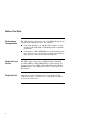
Educational Services
Installing the TF85 Tabletop
Cartridge Tape Subsystem
EK–TX85T–IG–003
Digital Equipment Corporation
First Edition, July 1991
Second Edition, September 1991
Third Edition, March 1992
The information in this document is subject to change without notice and should not be construed as a
commitment by Digital Equipment Corporation. Digital Equipment Corporation assumes no responsibility
for any errors that may appear in this document.
Copyright © Digital Equipment Corporation 1991, 1992
All Rights Reserved.
Printed in U.S.A.
The following are trademarks of Digital Equipment Corporation: CompacTape, DSSI, KFMSA, KFQSA,
MicroVAX, MicroVAX II, Q–bus, TF, TK, VAX 4000, VAX 6000, VAXserver, VMS, and the DIGITAL logo.
Contents
About This Guide . . . . . . . . . . . . . . . . . . . . . . . . . . . . . . . . . . . . . . . . . .
Before You Start . . . . . . . . . . . . . . . . . . . . . . . . . . . . . . . . . . . . . . . . . . .
Steps to Follow . . . . . . . . . . . . . . . . . . . . . . . . . . . . . . . . . . . . . . . . . . .
1
2
4
Contents–iii
About This Guide
Contents
This guide provides information for installing the TF85 tabletop
cartridge tape subsystem.
The TF85 tabletop subsystem is supported on the following
series of systems:
VAX 6000
VAX 4000
MicroVAX/VAXserver 3xxx (Q–bus)
MicroVAX II
Intended
Audience
This guide is for Digital Services personnel or qualified selfmaintenance customers who are installing the TF85 tabletop
cartridge tape subsystem on systems with DSSI bus adapters
in place. That is, the bus adapters to be used for connecting
the TF85 to the system must be embedded within the CPU
module or on an installed adapter module, such as the KFMSA
or KFQSA.
How to Use
This Guide
First read the next section, Before You Start, to prepare for
the installation. Then follow the procedure in Steps to Follow,
using the illustrations and examples as a guide.
1
Before You Start
Performance
Consideration
The VMS backup performance rate of the TF85 subsystem can
depend on the system processor. For example:
Connecting directly to an embedded bus adapter on such
systems as the VAX 4000 or VAX 6000 provides optimum
performance.
Connecting to a MicroVAX/VAXserver 3xxx (Q–bus) system
can reduce the rate of performance, but does not limit the
high capacity of data storage that the TF85 has.
Required Load
Device
The TF85, when connected to a KFQSA adapter installed
in a MicroVAX II or MicroVAX/VAXserver 3xxx system, does
not support booting of VMS or MicroVAX Diagnostic Monitor
(MDM) software. An additional load device is needed to boot
this software.
Required Tool
Although you can hand-tighten the screws that hold the
connectors in place, you need to use a flat blade screwdriver
to secure the connectors.
Continued on next page
2
Before You Start, Continued
Related
Documents
Keep the system and DSSI adapter documentation on hand for
referencing during the installation.
Order Number
Title
EK–432AA–IN
EK–436AB–IN
EK–396AB–TI
EK–335AC–IN
EK–337AB–TI
For Installations on VAX 4000 Systems
VAX 4000 Model 200 (BA215) Installation Guide
VAX 4000 Model 200 (BA430) Installation Guide
VAX 4000 Model 200 Technical Information
VAX 4000 Model 300 Installation Guide
VAX 4000 Model 300 Technical Information
EK–020AA–TI
EK–160AA–IN
EK–163AA–TI
For Installations on MicroVAX/VAXserver
3300 and 3400 Systems
MicroVAX 3300/VAXserver 3300 Technical Information
MicroVAX 3400/VAXserver 3400 Installation Guide
MicroVAX 3400/VAXserver 3400 Technical Information
EK–KFQSA–IN
EK–KFMSA–IM
DSSI Adapter Documents
KFQSA Module Installation and User Manual
KFMSA Module Installation and User Manual
EK–OTF85–OM
EK–OTK85–RC
Subsystem Documents
Tx85 Series Cartridge Tape Subsystem Owner’s Manual
Tx85 Tape Drive Operator’s Reference Card
3
Steps to Follow
Use the following procedure to install the TF85 tabletop
subsystem:
Unpack
1. The TF85 tabletop subsystem and its accessories ship
together in a box. Your cable kit is a separate order. Make
sure you have all the items on the contents listings:
Box Contents
Part Number
Description
TF85–TA
TF85 tabletop subsystem: a 5-1/4-inch drive and
a DSSI controller in a tabletop enclosure
TK85K–01
One CompacTape III cartridge
TK85–HC
One CleaningTape III cartridge
12–28766–28
Packet of DSSI node ID plugs
Country-specific
Power cord
36–28816–02
Sheet of foreign language decals
EK–TX85T–IG
This installation guide
EK–OTF85–OM
Owner’s manual
EK–OTK85–RC
Operator’s reference card
Continued on next page
4
Steps to Follow, Continued
Unpack
(continued)
Cable kit options are as follows:
Cable Kit
Part Number
Description
CK–SF100–LP
Cable kit with 9-foot DSSI cable for VAX 4000 models,
MicroVAX/VAXserver 3xxx series, or MicroVAX II.
CK–SF100–L6
Cable kit with 16-foot DSSI cable for VAX 4000 models,
MicroVAX/VAXserver 3xxx series, or MicroVAX II.
CK–SF100–L4
Cable kit with 25-foot DSSI cable for VAX 4000 models,
MicroVAX/VAXserver 3xxx series, or MicroVAX II.
CK–SF100–LM
Cable kit with 9-foot DSSI cable for VAX 6000 and 9000
systems.
CK–SF100–L5
Cable kit with 16-foot DSSI cable for VAX 6000 and
9000 systems.
CK–SF100–L3
Cable kit with 25-foot DSSI cable for VAX 6000 and
9000 systems.
If any item is missing or damaged, contact the delivery
agent or Digital sales representative.
NOTE
Save the packing materials until you are sure
you will not reship any items.
Continued on next page
5
Steps to Follow, Continued
Choose a Site
2. Place the TF85 on a flat, sturdy, level area such as a desk
or tabletop—not on the floor:
Avoid a site that is dusty or humid.
Allow enough space around the TF85 for ventilation and
for easy access to the front and rear.
Affix Decals
3. If applicable, choose the foreign language decals with the
language appropriate for your country and affix them over
the English labels on the TF85 front panel. One decal
adheres to the cartridge insert/release handle, the other
adheres to the indicator panel (see TF85 Front View).
Continued on next page
6
Steps to Follow, Continued
TF85 Front
View
The following illustration shows the front panel on the TF85
tabletop subsystem:
Cartridge Insert/Release Handle
Indicator Panel
Continued on next page
7
Steps to Follow, Continued
Familiarize yourself with the TF85 rear panel for this
installation:
TF85 Rear
View
2
3
1
4
5
DSSI node ID socket
DSSI signal connector in
DSSI signal connector out/termination
Power switch
Power connector
Continued on next page
8
Steps to Follow, Continued
Power Off the
System
4. Check that the system manager has performed the following
steps:
a. Back up all disk integrated storage elements (ISEs).
b. Shut down the operating system.
c.
Halt the system.
d. Remove power from the system.
Select a DSSI
Node ID
5. Select a DSSI node ID plug with an ID that is unique from
any other devices on the DSSI bus.
DSSI adapters typically have the highest node ID number(s)
on the bus (7 when one adapter is on the bus; 7 and 6
for two adapters; 7, 6, and 5 for three adapters, and so
on). Tape ISEs typically have a low DSSI node number
(in most cases 0). Disk ISEs are typically assigned the
remaining DSSI nodes, after adapters and tape ISEs have
been assigned.
When adding a second TF85x to a DSSI bus, remember
that no two devices on the DSSI bus can have the same ID
number.
NOTE
Save the spare DSSI node ID plugs for future
system reconfigurations.
6. Insert the DSSI node ID plug into the DSSI node ID socket
on the rear panel (TF85 Rear View
) by aligning the two
center prongs with the two center slots and pressing the
plug into place.
Continued on next page
9
Steps to Follow, Continued
Connect to the
DSSI Bus
7. Plug the DSSI cable into the leftmost TF85 DSSI connector
(TF85 Rear View
) by fitting the cable connector over the
two pins on the DSSI connector. First tighten the screws by
hand, then secure the connection with a screwdriver.
MLO-004240
Reduction 53%
LJ-00914-TI0
8. If this is the last device on this bus, attach the DSSI
terminator to the rightmost TF85 DSSI connector (TF85
Rear View
). Make sure the orientation of the terminator
is correct—it fits on the DSSI connector in one way only—
and push the terminator onto the connector. The spring
clips should lock the terminator in place.
Reduction 66%
MLO-004239
LJ-00924-TI0
Continued on next page
10
Steps to Follow, Continued
Connect to
the DSSI Bus
(continued)
NOTE
To remove the DSSI terminator for daisychaining, that is, connecting additional DSSI
devices to the TF85, squeeze the spring clips at
the bottom and top of the terminator as you pull
it straight out of the connector.
Remember to reinstall the terminator on the last
device of the DSSI bus.
REduction 63%
MLO-004238
LJ-00925-TI0
WARNING
Remove the DSSI terminator only after shutting
off power to the entire system, including the
DSSI bus.
9. Connect the other end of the DSSI cable to the DSSI
I/O bulkhead on the system. Follow the procedures in
the system or DSSI adapter documentation (see Related
Documents in this guide).
Continued on next page
11
Steps to Follow, Continued
Connect to
Power
10. Be sure the TF85 power switch (TF85 Rear View
to 0 (off).
) is set
11. Connect the power cord to the TF85 power connector
(TF85 Rear View
). Make sure the connector is fully
seated.
12. Connect the other end of the power cord to a nearby ac
outlet.
Power On the
TF85
13. Set the TF85 power switch on. The power-on self-test
(POST) runs automatically when you power on the TF85.
Observe the indicators on the front panel:
a. The indicators on the front panel turn on sequentially,
from top to bottom.
b. All four indicators turn on simultaneously for
approximately three seconds.
c.
The green Operate Handle indicator and the two orange
indicators turn off.
d. The yellow Tape in Use indicator blinks.
e. With no cartridge loaded, the green Operate Handle
indicator turns on and the beeper sounds.
POST ran successfully if you observed the above. Proceed to
step 14 in Power On the System. Otherwise, see the following
section, POST Failure.
12
Steps to Follow, Continued
POST Failure
If all four indicators on the TF85 front panel blink, POST did
not run successfully:
Check the cable connections to make sure that they are
secure.
Press the Unload button on the TF85 front panel to reset
the TF85 and restart POST.
If all four indicators blink again, you most likely have a
hardware failure. See the Tx800 Series Magazine Tape
Subsystem Service Manual (EK–TF857–SM).
Power On the
System
14. After successful completion of POST, have the system
manager perform the following steps:
a. Restore power to the system.
b. Configure the system to recognize the TF85.
c.
Restart the operating system.
Continued on next page
13
Steps to Follow, Continued
Configuration
Example
Configuration depends on the type of adapter or system you
have. Follow the procedures in the system or DSSI adapter
documentation (see Related Documents).
The following dialog is an example of configuring a VAX 4000
system in console I/O mode. The example uses the DUP utility
from system software and the PARAMS utility resident on the
TF85:
>>> SHOW DSSI
DSSI Bus 0 Node
-MIA10 (TF85)
DSSI Bus 0 Node
-DIA10 (RF71)
DSSI Bus 0 Node
-DIA11 (RF71)
DSSI Bus 0 Node
0 (T8DBBB)
1 (FRED)
2 (PEBBLES)
7 (*)
DSSI Bus 1 Node 0 (DINO)
-DIB0 (RF71)
DSSI Bus 1 Node 1 (BARNEY)
-DIB1 (RF71)
DSSI Bus 1 Node 7 (*)
>>>
>>> SET HOST/DUP/DSSI/BUS:0 0 PARAMS
Starting DUP server...
Copyright (c) 1990 Digital Equipment Corporation
PARAMS>
The above command example uses BUS:0 0. For your
application, use the format BUS:n m where n = the bus number
and m = the node number on which you have installed the TF85.
Continued on next page
14
Steps to Follow, Continued
Configuration
Example
(continued)
PARAMS> SHOW /ALL
Parameter
Current
UNITNUM
0
FORCEUNIT
1
NODENAME
T8DBBB
FORCENAME
0
SYSTEMID 420000F00002
Default
0
1
TF85
0
Minimum
0
0
Maximum
255
1
0
1
Radix
Decimal
Decimal
Ascii
Decimal
Quad
PARAMS> SET NODENAME WILMA
PARAMS> WRITE
Changes require controller initialization, ok? [Y/(N)] Y
PARAMS> EXIT
>>>
See the Tx85 Series Cartridge Tape Subsystem Owner’s
Manual for details on using the PARAMS utility to set TF85
parameters.
Test the
Installation
15. Once the system is configured to recognize the TF85, load
a previously recorded data cartridge into the TF85 and test
the installation by running DRVEXR, a local program on
the TF85. (See the Tx85 Series Cartridge Tape Subsystem
Owner’s Manual for cartridge loading instructions.)
Continued on next page
15
Steps to Follow, Continued
DRVEXR
Example
CAUTION
During the write/read operation, DRVEXR destroys
the data on the cartridge. Be sure to use a scratch
data cartridge.
DRVEXR is an intensive data transfer test that indicates the
overall integrity of the TF85. The following example shows
running DRVEXR from console I/O mode:
>>> SET HOST/DUP/DSSI/BUS:0 0 DRVEXR
Starting DUP server...
Copyright (c) 1990 Digital Equipment Corporation
Write/read anywhere on medium? [1=Yes/(0=No)] 1
User Data will be corrupted. Proceed? [1=Yes/(0=No)] 1
Test Time in Minutes [(10) - 100] 10
Minutes to Complete: 10
Statistical Report
Test Name: DRVEXR, Pass 1
Random Seed:
3075021312
Byte Count:
0
Pattern Number:
9
Data Errors:
Read
Write
Retries:
0
0
ECC:
0
0
Hard:
0
0
Data Compare Errors:
0
Mispositions:
0
Kbytes Written:
190221
Read:
82133
Test Passed
Continued on next page
16
Steps to Follow, Continued
DRVEXR
Messages
DRVEXR messages include the following:
Type
Message
Question
Write/read anywhere on the medium? [1=YES
/(0=NO)]
Answering 0 (NO) results in a read-only test. Successful
operation of the read-only test requires a previously written
tape. Answering 1 (YES) results in the next question being
asked.
User data will be corrupted, proceed? [1=YES
/(0=NO)]
Answering 0 (NO) results in a read-only test. Answering 1
(YES) permits write and read operations anywhere on the tape.
Test time in minutes? [10-100]
Answer with an execution time from 10 to 100 minutes.
Information
nnn minutes to complete.
nnnnnnnn bytes read.
nnnnnnnn bytes written.
Termination
Complete.
Fatal error
Unit is currently in use.
Operation aborted by user.
XXXX - Unit diagnostics failed.
XXXX - Unit read/write test failed.
Continued on next page
17
Steps to Follow, Continued
Correct Any
Problems
If the TF85 fails during power-up or operation, use the following
table to determine the problem and the action to take:
If. . .
Then. . .
You should. . .
The system does
not recognize the
TF85
The DSSI cable is
loose
Tighten the
connector on each
end of the DSSI
cable to make sure
the connectors are
fully seated.
The DSSI
terminator is
not present or is
loose
Install the
terminator; make
sure the terminator
is fully seated.
The DSSI node ID
is not unique
Change the node ID
and reconfigure the
system.
The bus
termination
or DSSI cable
connections may
be incorrect
Make sure the DSSI
bus is terminated
and the terminator
LED is on to
avoid incorrect
bus termination.
You are finding
fatal or nonfatal
errors for which
you cannot
determine the
cause
Continued on next page
18
Steps to Follow, Continued
Correct Any
Problems
(continued)
If. . .
Then. . .
You should. . .
You are finding
fatal or nonfatal
errors for which
you cannot
determine the
cause
The ac power
source grounding
may be incorrect
Use an ac outlet
for the TF85 on
the same ac line
that is powering the
system.
The green LED
on the DSSI
terminator is
not on
The terminator
has no power
Check for a loose
cable connection
or a bad DSSI
cable, or try another
terminator.
The cartridge will
not load
The cartridge
insert/release
handle is
not correctly
positioned
See the owner’s
manual for
operating
instructions.
The TF85 does not
power up
The TF85 has no
power
Check the TF85
power cord
connections, with
the TF85 power
switch off.
Continued on next page
19
Steps to Follow, Continued
Correct Any
Problems
(continued)
Ready to
Operate
20
If. . .
Then. . .
You should. . .
All four indicators
on the TF85 front
panel blink
A drive fault has
occurred
Press the Unload
button on the
TF85 front panel
to clear the error.
If the error does
not clear, see the
service manual
(EK–TF857–SM).
16. The installation is complete, and the TF85 tabletop
subsystem is ready for use, once the DRVEXR test passes.
The Tx85 Series Cartridge Tape Subsystem Owner’s Manual
provides operating instructions.