1
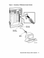
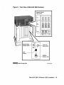
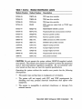
MicroVAX 3800
VAXserver 3800
Installation
Order Number EK-164AA-IN-001
digital equipment corporation
maynard, massachusetts
March 1989
The information in this document is subject to change without notice and should not be
construed as a commitment by Digital Equipment Corporation.
Digital Equipment Corporation assumes no responsibility for any errors that may appear in
this document.
The software, if any, described in this document is furnished under a license and may be used
or copied only in accordance with the terms of such license. No responsibility is assumed
for the use or reliability of software or equipment that is not supplied by Digital Equipment
Corporation or its affiliated companies.
© Digital Equipment Corporation 1989. All rights reserved.
Printed in U.S.A.
The READER'S COMMENTS form on the last page of this document requests the user's
critical evaluation to assist in preparing future documentation.
The following are trademarks of Digital Equipment Corporation:
COMPACTape
DDCMP
DEC
DECmate
DECnet
DEC server
DECUS
DECwriter
DELNI
DELQA
DEQNA
DESTA
DIBOL
DSSI
MASSBUS
MicroVAX
PDP
P/OS
Professional
Q-bus
Rainbow
ReGIS
RQDX
RSTS
RSX
RT
ThinWire
ULTRIX
UNIBUS
VAX
VAXcluster
VAXELN
VAXlab
VMS
VT
Work Processor
mBmBO!a'"
ML-S933
FCC NOTICE: The equipment described in this manual generates, uses, and may emit
radio frequency energy. The equipment has been type tested and found to comply with the
limits for a Class A computing device pursuant to Subpart J of Part 15 of FCC Rules, which
are designed to provide reasonable protection against such radio frequency interference when
operated in a commercial environment. Operation of this equipment in a residential area
may cause interference, in which case the user at his own expense may be required to take
measures to correct the interference.
This document was prepared using VAX DOCUMENT, Version 1.1.
Contents
Preface.............................................
v
1
Verify Site Preparation . . . . . . . . . . . . . . . . . . . . . . . . .
1
2
Check Your Shipment. . . . . . . . . . . . . . . . . . . . . . . . . . .
Unpack Your Shipment .. . . . . . . . . . . . . . . . . . . . . . . . . .
1
1
3
Place the System . . . . . . . . . . . .. . . . . . . . . . . . . . . . . . .
4
4
Install the Console Terminal .. . . . . . . . . . . . . . . . . . .
Perform Set-Up Operations. . . . . . . . . . . . . . . . . . . . . . . .
Connect the Console Terminal to the System. . . . . . . . . . .
6
6
8
5
Set Controls on Your System . . . . . . . . . . . . . . . . . . . .
12
6
Connect Additional Devices to the System . . . . . . .
Connect Terminals and Serial Printers. . . . . . . . . . . . . . .
Connect Parallel Printers to the System . . . . . . . . . . . . . .
Connect Synchronous Modems to the System ..........
Connect Asynchronous Modems to the System .........
Connect an Internal Modem to Telephone Lines ........
Connect to an Ethernet Network. . . . . . . . . . . . . . . . . . . .
14
16
19
20
20
22
30
7
Connect the System Power Cable. . . . . . . . . . . . . . . .
36
8
Turn on the System and Select a Language ......
39
9
Attach the Front Panel to the System. . . . . . . . . . . .
41
10
After Installation. . . . . . . . . . . . . . . . . . . . . . . . . . . . . . .
42
2.1
4.1
4.2
6.1
6.2
6.3
6.4
6.5
6.6
iii
Figures
1
2
3
4
5
6
7
8
9
10
11
12
13
14
15
16
17
18
19
20
21
22
23
24
Shipping Carton Contents . . . . . . . . . . . . . . . . . . . . . . . . . . .
Sliding the System into Place ........................
Connecting a VT300-Series Console Terminal . . . . . . . . . . . .
Connecting a VT200-Series Console Terminal . . . . . . . . . . . .
Front View of MicroVAX. 3800 Enclosure. . . . . . . . . . . . . . . .
Connecting Devices to the CXA16 Module . . . . . . . . . . . . .. .
Connecting Devices to the Cable Concentrator ........ '.' . .
Mounting the Cable Concentrator . . . . . . . . . . . . . . . . . . . . .
Connecting a Modem to a CXY08 Module ...............
Disconnecting the Telephone Line (Single- and Multi-Line
Service) .........................................
Installing Telephone Cord (Single- and Multi-Line Service) . .
Connecting Modem to Telephone (Single- and Multi-Line
Service) .........................................
Connecting Modem to Wall-Mounted Jack (Data Jack Service)
- Telephone-to-Wall-Jack Connection. . . . . . . . . . . . . . . . . .
Connecting Modem to Wall-Mounted Jack (Data Jack Service)
- Telephone-to-DFA01 Connection. . . . . . . . . . . . . . . . . . . .
ThinWire Cable, T-Connector, and Terminator. . . . . . . . . . . .
Making a ThinWire Ethernet Connection. . . . . . . . . . . • . . .
Form the Upper Cable in a Loop . . . . . . . . . . . . . . . . . . . . . .
Grounding ThinWire Ethernet Cable on the DESQA Module
Making a Standard Ethernet Connection. . . . . . . . . . . . . . . .
Power Cables. . . . . . . . . . . . . . . . . . . . . . . . . . . . . . . . . . . . .
Attaching Power Cable to the System . . . . . . . . . . . . . . .. . .
Language Selection Menu ...........................
Example of a Successful Power-On Test. . . . . . . . . . . . . . . . .
Attaching the Front Panel. . . . . . . . . . . . . . . . . . . . . . . . . . .
3
5
9
11
13
17
18
19
21
23
24
25
27
29
30
31
32
33
35
37
38
39
40
41
Tables
.1
iv
Module Identification Labels
14
Preface
This manual describes how to install your MicroVAX 3800 or VAXserver
3800 system. It assumes you have unpacked the system according to
directions on the shipping carton. Installation includes the following steps:
1. Verifying site preparation
2. Checking your shipment
3. Placing the system
4. Installing the console terminal
5. Setting controls on the system
6. Connecting additional devices to the system
7. Connecting the power cable
8. Turning on the system and selecting a language
9. Attaching the front panel
Before installing a DIGITAL system, review the system warranty. The
terms of your warranty agreement with DIGITAL, may require that a
qualified DIGITAL service representative install your system. Contact your
local DIGITAL representative if you have any questions.
NOTE: VAXserver 3800 systems are designed to offer maximum performance
for applications that do not require timesharing. Some of the devices referred
to in this manual are designed for multiuser systems and may not be suitable
for a VAXserver system. Contact your DIGITAL representative if you have
any questions about whether use of a specific device is appropriate for your
VAXserver system.
Dual-host systems must be installed by a DIGITAL service representative.
For more information on dual-host systems, refer to your Micro VAX 3800
VAXserver 3800 Operation manual.
v
Conventions
The following conventions are used in this book:
Convention
Meaning
A symbol denoting a terminal key used in text and examples in this book.
For example, Break indicates that you press the Break key on your tenninal
keypad. Return indicates that you press the Return key on your terminal
keypad.
NOTE
Provides general information about the current topic.
CAUTION
Provides information to prevent damage to eqUipment or software.
WARNING
Provides information to prevent personal injury.
vi
1 Verify Site Preparation
f
\
'
Before receiving your system, you should have received a Micro VAX Site
Preparation manual. This guide describes the physical, environmental,
and electrical requirements to operate your system. For your convenience,
a copy of this guide is also included in your Customer Hardware Information
kit. If you have not already done so, please read the guide and follow its
instructions for preparing your site.
The installation instructions that follow assume the site meets all the
installation requirements listed in the Micro VAX Site Preparation manual.
The instructions also assume all terminal data lines, telephone lines, and
network lines that you plan to connect to your system are in place and
clearly labeled.
2 Check Your Shipment
NOTE: Save all packing materials if you plan to reship the system.
Your shipment may include several cartons.
•
One contains the system unit with unpacking instructions on the side.
•
One contains cables for connecting additional devices to your system.
•
Another, with unpacking instructions on the side, contains components
of the console terminal.
•
Another, marked "Software," contains software documentation, system
software, diagnostic software, and a software license.
Depending on your order, your shipment may also include some of the
following equipment:
•
Additional terminalCs)
•
PrinterCs)
•
ModemCs)
2.1 Unpack Your Shipment
Before installing your system, unpack all cartons and check the contents
against the shipping list to ensure you have received everything you
ordered.
MicroVAX 3800 VAXserver 3800 Installation
1
If any item is missing or damaged:
•
Contact your delivery agent.
•
Contact your DIGITAL sales representative.
Find the carton containing the system unit and unpack the system
according to the instructions on the carton. Figure 1 shows the contents of
the shipping carton.
Release the shipping brackets according to the instructions on the yellow
label attached to the front of the system unit. When you have completed
this, remove the label from the front of the unit.
CAUTION: Before continuing installation, verify that your system's power
requirements match your power source. The correct voltage for the system
is listed on the serial number label next to the left power supply (see
Figure 1). If the voltage listed matches your power source, continue with
the installation. If the voltage does not match your power source, do not
continue. Contact your DIGITAL sales representative.
2
MicroVAX 3800 VAXserver 3800 Installation
Figure 1:
Shipping Carton Contents
DECconnect
Office Cable
Adapter
H8571-A
Cable Clamp
Keys to
Front Panel
&
e
~
Terminators
T-Connector
~Screwdriver
~System
~ Power Cable
-
Front Panel
,r------,-- Hand Holds
erial Number Label
MLO-0022S8
MicroVAX 3800 VAXserver 3800 Installation 3
3 Place the System
The installation instructions that follow assume you have correctly followed
the unpacking instructions on the carton.
CAUTION: Moving and operating your system without releasing the
shipping brackets may damage the mass storage devices.
After unpacking your system, you can move it into position in two ways, as
shown in Figure 2.
•
You can roll it sideways.
•
You can gently slide or walk it backward or forward by gripping the
handholds on the side of the unit.
WARNING: The system weighs between 50 kg (110 lb) and 64 kg (140 lb),
depending on the options installed. Use two or more people to maneuver the
system.
During installation, leave space behind the system for routing cables
underneath the system unit. Once installation is complete, you can place
the system base directly against a wall. No rear ventilation is required.
·4
MicroVAX 3800 VAXserver 3800 Installation
Figure 2:
Sliding the System into Place
Hand Holds
Slides Front to Back
Rolls Left to Right
MLO·002269
MicroVAX 3800 VAXserver 3800 Installation 5
4 Install the Console Terminal
The next step in installing your MicroVAX 3800 or VAXserver 3800 system
is to set up the console terminal. You use the console terminal to
communicate with your system. Your console terminal is packed with the
following:
•
Video monitor
•
Keyboard and keyboard cable
•
Console terminal power cable
•
Documentation, including an installation guide and user's manual
Unpack the terminal and documentation. Use the instructions in the
terminal installation guide to connect the various components of your
terminal.
Read the instructions on installing and using your terminal that were
provided with your console terminal. Before you connect the console
terminal to your system, turn on the terminal to make sure it works
correctly and perform some set-up operations.
The terminal performs a self-test every time you turn it on. The
documentation for your terminal describes a successful self-test and
possible error messages that display if the terminal is not operating
properly. Once the terminal passes the self-test, you should perform some
set-up operations.
4.1 Perform Set-Up Operations
Set-up involves choosing how your video terminal operates. Certain
parameters must be selected so that your terminal can communicate with
your system: the terminal's baud rate should be set to 9600, and receive
speed should be set to equal the transmit speed.
You choose set-up options from a series of menus that display when you
press the ISet·Upl key on the terminal keyboard. Set-up instructions for
terminals vary according to model, or, in some cases, according to which
read-only memory (ROM) cartridge is installed in your terminal. Be sure
to read the documentation provided with your terminal.
While most default settings are acceptable, you should perform the set-up
procedure for your terminal to ensure appropriate set-up values. The two
examples that follow provide set-up instructions for VT300- and VT200series terminals.
6
MicroVAX 3800 VAXserver 3800 Installation
For VT300-Series Terminals
1. Press (Set-Up( to display the Set-Up Directory screen.
2. Use the arrow keys to select the "Communications Set-Up" option and
press (Enter(.
3. Make sure the "Transmit Speed" option in the "Current Setting" column
is set to 9600. Use the left and right arrow keys to change the setting.
4. Make sure the "Receive Speed" option in the "Current Setting" column
is set to "receive=transmit." Use the down arrow to move the cursor to
this option, and the left and right arrows to change the setting.
5. Press (Select( to return to the Set-Up Directory screen.
6. Use the arrow keys to select the "Global Set-Up" option. Press (Enter( to
display the Global Set-Up screen and use the arrow keys to select the
"Comml Port" option.
7. If the port in the "Current Setting" column is selected for "RS-232,"
press (Enterl to select the "DEC-423" port.
8. Press (selectl to return to the Set-Up Directory screen.
9. Use the arrow keys to select the "Save Current Settings" option. Press
(Enterl to save all current settings; then press (set-Upl to exit the Set-Up
Directory.
For VT200-Series Terminals
1. Press
(Set-Upl
to display the Set-Up Directory screen.
2. Use the arrow keys to select the "Default" option and press IEnterl. Default
correctly sets all values except transmit speed.
3. Use the arrow keys to select the "Comm" option and press (Enterl to display
the Communications Set-Up menu.
4. Use the arrow keys to select the "Transmit" option and, using (Enterl, set
the speed to 9600.
5. Use the arrow keys to select the "To Directory" option and press (Enterl.
6. Use the arrow keys to select the "Save" option and press (Enterl; this option
stores the set-up values. Then press (Set-upl to exit the Set-Up Directory.
Once you have tested your terminal and performed set-up operations, you
are ready to connect the console terminal to the system.
MicroVAX 3800 VAXserver 3800 Installation
7
4.2 Connect the Console Terminal to the System
Connecting the console terminal to the system involves attaching one end
of a cable to the cover panel of the central processing unit (CPU) module,
and the other end of the cable to a communications port in the back of the
terminal.
The CPU cover panel covers slots 1 and 2 and has two labels, KA655 and
MS650. affixed to the top of the panel. The port on the back of the console
terminal varies with the type of terminal. Refer to the separate illustrations
and instructions that follow to connect VT300-series and VT200-series
terminals.
For VT300-Series Terminals
Connect the console terminal to your system as follows:
1. Tum off the console terminal.
2. Find the terminal cable in the accessories box. The cable is labeled
"DECconnect Office Cable" and has a DEC-423 modular plug on each
end.
3. Connect the terminal cable to the DEC-423 modular jack labeled "1" on
the rear of your terminal, according to the instructions in your terminal
installation guide.
4. Feed the other end of the cable under the system base, either from
behind or from the side. Draw up the cable and plug it into the DEC423 modular jack labeled "AI" on the CPU cover panel, as shown in
Figure 3.
8 MicroVAX 3800 VAXserver 3800 Installation
Figure 3:
Connecting a VT300-Series Console Terminal
. -_ _ DECconnect
Office Cable
Feed Cable
Under System
MicroVAX 3800 VAXserver 3800 Installation 9
For VT200-Series Terminals
Connect the console terminal to your system as follows:
1. Turn off the console terminal.
2. Find the terminal cable and modular-jack-to-25-pin adapter in the
accessories box. The cable is labeled "DECconnect Office Cable" and
has a DEC-423 modular plug on each end. The adapter is labeled
"H8571-A."
3. Plug one end of the cable to the 25-pin adapter; then connect the adapter
to the 25-pin communications port labeled "COMM" on the rear of your
terminal, according to the instructions in your terminal installation
guide.
4. Feed the other end of the cable under the system base, either from
behind or from the side. Draw up the cable and plug it into the DEC423 modular jack labeled "Al" on the CPU cover panel, as shown in
Figure 4.
You are now ready to set the controls on your system.
10
MicroVAX 3800 VAXserver 3800 Installation
Figure 4:
Connecting a VT200-Series Console Terminal
~_ _
DECconnect
Office Cable
Feed Cable
Under System
Adapter
H8571-A
MicroVAX 3800 VAXserver 3800 Installation
11
5 Set Controls on Your System
All controls are on the front of the chassis, as shown in Figure 5.
Your system's integrated storage elements and tape drives are shock
mounted in a tray across the top of the system. The RF71 integrated storage
elements are behind the Operator Control Panel (OCP), which contains
controls and indicators for each of the storage elements. Make sure the
Write-Protect switches are in the out (write enabled) position; the Halt
button should also be in the out position (not lit).
The following controls are located on the CPU cover panel covering slots 1
and 2.
•
Break EnablelDisable Switch. The factory setting is break disable
(down), indicated by the dot outside the circle. Leave the switch
set to disable while you start the system for the first time and run
diagnostic software to test the· system. With break disabled, your
system automatically boots software when powered up.
•
Power-Up Mode Switch. This 3-position rotary switch determines how
the system powers up. The factory setting is Run Mode, indicated by
an arrow. Set the switch to the Language Inquiry Mode (the uppermost
position), indicated by a human profile, before you power up your system
the first time.
•
Baud Rate. The baud rate switch is on the inside of the panel covering
the CPU module. The factory setting is 9600. You should have
already set your console terminal baud rate to 9600 (see Section 4.1).
The system and the terminal must be set to the same baud rate to
communicate.
You are now ready to connect additional devices to your system.
12 MicroVAX 3800 VAXserver 3800 Installation
Figure 5:
Front View of MicroVAX 3800 Enclosure
Operator Control
Panel (OCP)
~ ~Q]
c:J c:J c:J
DRIVE
Unit Number
Fault
GJ EI Gl
GEl GJ
Writ8~
Protect
Ready
SYSTEM
18 [2] 1c:J1
Restart}
Halt
Run
Break Enable/
Disable Switch
~:iO -l>€;_
~
~~\:)I 5tB;. J
@
LED
DI~lay
Power-Up
Mode Switch
(.!)
l ffi· J
_-i---"/I
• •d~uill~ Mass Storage Shelf
Modified
Modular Jack
MLO-002272
MicroVAX 3800 VAXserver 3800 Installation 13
6 Connect Additional Devices to the System
You can connect additional devices at this time, or you can complete
installation and load system software before connecting other devices. Skip
to the next step if you prefer to connect additional devices later. Use the
instructions in this step when you are ready to connect the devices.
You make all connections directly to the module cover panels. Begin with
the module at the far right. As you complete connections for each module,
move left to the next module. The next five sections explain how to connect
each type of device.
To help you make the proper connections, each module cover has an
identifying label at the top. The label contains the option number and
module number. Table llists the identifying labels for all modules requiring
connections. Use Table 1 to identify the modules as you connect additional
devices to your system.
Table 1: Module Identification Labels
Module Number Option Number
Description
M7625
KA655-AA
MicroVAX 3800/3900 CPU
M7625
KA655-BA
VAXserver 3800/3900 CPU
M762 I-A
MS650-BA
MicroVAX/ VAXserver 3000-series memory
M78578
MRVll-D
Programmable read-only memory
M7769
KFQSA-SA
DSSI mass-storage adapter
M3127-PA
DESQA
Ethernet adapter
M3118-YA
CXAI6-SA
16-Line asynchronous serial interface (RS-423A, no modem support)
M3118-YB
CXBI6-SA
16-Line asynchronous serial interface (RS-422,
noise immune)
M3119-YA
CXY08-SA
8-Line asynchronous serial interface (full modem
support)
M3018
DSVll-SA
2-Line synchronous serial interface (full modem
support)
M3121-PA
DFAOI-AA
2-Line asynchronous serial interface with integralmodem
M8020-PA
DPVll-SA
Synchronous serial line interface
M8086-PA
LPVll-SA
Dual parallel printer interface
14 MicroVAX 3800 VAXserver 3800 Installation
Table 1 (Cont.): Module Identification Labels
Module Number Option Number
Description
M7559-PA
TQK70-SA
TK70 tape drive controller
M7546-PA
TQK50-SA
TK50 tape drive controller
M7206-PA
TSV05-SA
TS05 tape drive controller
M7740-PA
KLESI
RV20 write-once optical disk (or TU81E tape)
controller
M7552-PA
KRQ50-SA
RRD40IRRD50 CDROM controller
M7500-PA
KMVlA-SA
Programmable data communications interface
M7658-PA
DRQ3B-SA
Real-time parallel interface
M7651-PA
DRVIW-SA
Real-time parallel interface
M8634-PA
IEQll-SA
IEEE instrument bus DMA controller
M3125-PA
IBQOl-SA
BITBUS-to-Q-bus DMA controller
AIOO9-PA
AAVll-SA
Digital-to-analog converter
AIOO8-PA
ADVll-SA
Analog-to-digital converter
A030-PA
ADQ32-SA
Analog-to-digital converter
M4002-PA
KWVll-SA
Programmable real-time clock
A026-PA
AXVll-SA
D/A and AID converter
CAUTION: Do not operate the system without DIGITAL-supplied module
cover panels. The module cover panels are required to protect the equipment
and to meet international regulatory standards. Do not substitute other
cover panels as they may not meet the required specifications.
Operating the system without the module cover panels has the following
consequences:
•
The system may overheat due to inadequate air circulation.
•
The system will not comply with FCC and VDE requirements for
shielding and may produce electrical interference that affects other
equipment.
•
The system is susceptible to electrical interference or damage from
external sources.
MicroVAX 3800 VAXserver 3800 Installation
15
6.1 Connect Terminals and Serial Printers
You can connect up to 16 terminals and/or serial printers for each CXA16
or CXB16 module installed in your system. If the site has been prepared
properly, the lines for the additional terminals and printer(s) are clearly
labeled, and terminate near the system.
You do not connect the terminals and printers directly to the system, but
to a cable concentrator (H3104), which has connections for up to eight
terminals and printers. You then connect the cable concentrator to the
system with a BC16D cable. The cable carton contains two H3104 cable
concentrators and two BC16D cables for each CXA16 module in your
system.
Connect the additional terminals and printers as follows:
1. Find the H3104 cable concentrator and BC16D cable in the cable carton.
2. Feed one end of the BC16D cable under the system box from the back.
or side and plug it into the connector. If you are going to connect both
BC16D cables, connect the first to the connector labeled 8-15 on the
CXA16 cover panel. If you are going to use only one BC16D cable,
connect the cable to the connector labeled 0-7. Lock the connector into
place by using the bail latches shown in Figure 6.
3. Plug the other end of the BC16D cable into the cable concentrator. Lock
the connector into place by using the bail latches.
16 MicroVAX 3800 VAXserver 3800 Installation
Figure 6:
Connecting Devices to the CXA16 Module
Bail
Latches
BC16D _ _+l1>li
Cable
MLO-002273
MicroVAX 3800 VAXserver 3800 Installation 17
Figure 7:
Connecting Devices to the Cable Concentrator
BC16D Cable
H3104Cable
Concentrator
(Front View)
Bail
Latches
To Host
MLO-O02274
4. Connect each printer and terminal cable directly to one of the modified
modular jacks on the cable concentrator, as shown in Figure 7.
5. If you have not already done so, connect the remote terminal or printer
to the other end of the cable. Your terminal or printer documentation
shows how to connect the cable. If the printer or terminal does not have
a modified modular jack connection, use a passive adapter (H8571-A),
available in 25- and 9-pin models.
Follow the same procedure for connecting a second BCI6D cable to the
CXAI6, except plug the cable into the connector labeled 0-7.
18 MicroVAX 3800 VAXserver 3800 Installation
You can mount the cable concentrator on a wall. Wall mounting enables
you to keep cables off the floor. Use two screws, as shown in Figure 8.
NOTE: Be sure that you mount the cable concentrator less than 7.6 meters
(25 feet) from the system, to ensure the BC16D cable reaches the system.
Figure 8:
Mounting the Cable Concentrator
MLO-000651
6.2 Connect Parallel Printers to the System
You can connect up to two parallel printers for each LPVll module installed
in your system.
Connect parallel printers to the LPVll module as follows:
1. Find the BC27L-30 cable(s) in the cable carton.
2. Feed one end of the first BC27L cable under the system box from the
back or side. Plug it into the connector labeled J1 on the LPVll module
cover panel. Lock the connector into place by using the bail latches.
3. Plug the other end of the BC27L cable into the printer.
Follow the same procedure for connecting a second printer to the LPVll
module, except plug the cable into the connector labeled J2 on the LPVll
cover panel.
MicroVAX 3800 VAXserver 3800 Installation 19
6.3 Connect Synchronous Modems to the System
You can connect two synchronous modems to your system for each DSVll
module installed in the system.
Connect a synchronous modem to a DSVll module using the protocolspecific adapter and extension cables as follows:
1. Feed the female end of the 0.6 m (24 in) adapter cable (BC19-B/-DIE/-F) under the system unit from the back or side and connect it to the
DSVll module. Tighten the two screws on the cable connector using
the screwdriver shipped with your system.
2. Connect the extension cable (BC55D, BC22F, or BC19L) to the other end
of the adapter cable. Secure the cables by tightening the two screws at
the connection.
3. Connect the other end of the extension cable to the modem. Refer to
your modem documentation for the location of the connector, and for
instructions on using your modem.
6.4 Connect Asynchronous Modems to the System
You connect asynchronous modem lines to the CXY08 module, which
supports up to eight lines.
To connect a modem to a CXY08 module, see Figure 9 and refer to the
following instructions:
1. Find the BC19N-12 cable in the cable carton.
2. Feed one end of the cable under the system and plug it into the
connector. If you are going to use both BC19N-12 cables, connect the
first to the connector labeled 4-7 on the CXY08 module cover panel. If
you are going to use only one cable, connect the cable to the connector
labeled 0-3. Lock the connector into place with the bail latches.
3. Attach a modem to one of the four connectors at the opposite end of
the cable. If you want to place the modem farther· away from the
system, attach a BC22F modem cable between the cable assembly and
the modem. Refer to your modem documentation for the location of the
connector, and for instructions on using your modem.
Repeat the same procedure for connecting a second BC19N cable, except
plug the cable into the connector labeled 0-3.
20 MicroVAX 3800 VAXserver 3800 Installation
Figure 9:
Connecting a Modem to a CXV08 Module
Bail
Latches
BC19N-12
Cable
Assembly
7--:::~~-~ Feed Cable Under
System Unit and
Through Opening
MLO-002275
MicroVAX 3800 VAXserver 3800 Installation 21
6.5 Connect an Internal Modem to Telephone Lines
NOTE: The DFAOI modem is available for u.s. and Canadian
customers. Depending on the country you live in, the Telecommunication
Administration (PTT) may not allow you to connect private integral modems
to the public switched telephone network. Call your DIGITAL representative
for information on modem availability in your country.
DFA01 Modem
You connect the DFAOl module to telephone lines. The DFAOl module
supports two modems, modem A and modem B. Each modem requires its
own telephone.
The DFAOl modem connects to the following basic types of dial-up telephone
service:
•
RJllC (United States) and CAllA (Canada) standard single-line
telephone service. The switchpacks are factory set for this service. (If
you have this service, you have one wall-mounted modular telephone
jack per telephone.)
•
RJ12CIRJ13C (United States) and CA12A1CA13A (Canada) telephone
service. The switchpacks are factory set for this service. (If you have
this service, you have one wall-mounted modular telephone jack per
telephone.)
•
RJ41SIRJ45S (United States) and CA41AlCA45A (Canada) data jack
telephone service. (If you have this service, you have two wall-mounted
modular telephone jacks per telephone.)
NOTE: If you do not know which telephone service you are using, call your
telephone company. Information about the type of telephone service you are
using is readily available to you as a telephone customer.
RJ11C/CA11A, RJ12C/CA12A, and RJ13C/CA13A Service
Use the following procedure to connect the DFAOl modem to RJllC/CAllA,
RJ12C/CA12A, or RJ13C/CA13A service.
NOTE: If you plan to use both modem A and modem B, you will need two
telephones, one for each modem.
22
MicroVAX 3800 VAXserver 3800 Installation
1. Disconnect the telephone line from the wall-mounted modular telephone
jack. Leave the other end of the telephone line connected to the
telephone, as shown in Figure 10.
Figure 10: Disconnecting the Telephone Line (Single- and Multi-Line
Service)
Locking Tab
Wall-Mounted
Modular
Telephone Jack
Squeeze
Locking Tab
and Pull
From Jack
Telephone
MicroVAX 3800 VAXserver 3800 Installation 23
2. Take one end of one of the cords included with the DFA01 modem
(17-00089-01) and plug it into the top jack on the DFA01 cover panel
(modem A). The top jack on the DFA01 cover panel is marked with the
line icon, as shown in Figure 11.
Figure 11: Installing Telephone Cord (Single- and Multi-Line Service)
Wall-Mounted
Modular
Telephone Jack
Line Icon
Modem
A
Modem
B
Telephone Cord
(17-00089-01)
MLO-O00654
3. Connect the other end of the cord to the wall-mounted telephone jack.
4. To install voice communication on modem A, take the end of the
telephone line that you disconnected from the wall jack in step 1 and
connect it to the second jack from the top of the DFA01 cover panel, as
shown in Figure 12. This jack is marked with the telephone icon.
24 MicroVAX 3800 VAXserver 3800 Installation
Figure 12: Connecting Modem to Telephone (Single- and Multi-Line
Service)
Wall-Mounted
Modular
Telephone Jack
Line Icon
Modem
A
Telephone
MLO-000655
If you do not plan to use modem B, do not perform the following step.
If you require use of a second modem, set up modem B for use by
continuing with step 5.
5. Using a second telephone, set up modem B by following the same
procedure used to engage modem A. Notice, however, that the jack
positions on the DFAOI cover panel are reversed for modem B. The
bottom jack on the DFAOI cover panel is marked with a line icon; the
second jack from the bottom is marked with a telephone icon. Connect
the wall-mounted modular jack to the bottom jack on the DFAOI cover
MicroVAX 3800 VAXserver 3800 Installation 25
panel. Connect the telephone line to the second jack from the bottom
of the cover panel.
RJ41 S/CA41 A and RJ45S/CA45A Service
Use the following procedure to connect the modem to RJ41S/CA41A and
RJ45S/CA45A data jack service. You will need a standard 8-wire telephone
cord (not supplied with the DFA01 modem). If you have this service, you
have two wall-mounted modular telephone jacks per telephone.
NOTE: If you plan to use both modem A and modem B, you will need two
telephones, one for each modem.
Do not unplug the telephone line from the wall-mounted modular telephone
jack.
1. Connect one end of an 8-wire telephone cord (not supplied with the
DFA01 modem) into the top jack on the DFA01 cover panel (modem A).
The top jack on the cover panel is marked with the line icon.
2. Connect the other end of the telephone cord into a second wall-mounted
modular telephone jack, as shown in Figure 13.
If you require voice communication on modem A, refer to step 4 for
more information.
3. If you do not plan to use modem B, skip this step and proceed to step
4. If you plan to use modem B, connect a second 8-wire telephone line
to the bottom jack on the DFA01 cover panel, marked with a line icon.
(Notice that the jack positions are reversed for modem B.) Connect the
other end of the cord to a wall-mounted modular telephone jack.
If you require voice communication on modem B, refer to step 4 for
more information.
4. If you require voice communication with the DFA01 modem, you may
want to consider this step.
You can install voice communication on the DFA01 modem in one of two
ways. Depending on the location of your system, telephone, and wallmounted modular telephone jacks, one of the following two methods
of installing voice communication may be more appropriate for your
system.
The first way of installing voice communication is established for both
modem A and modem B in the preceding steps. The telephone is
connected to the wall-mounted modular telephone jack, which is, in
turn, connected to the DFA01 cover panel (see Figure 13).
26 MicroVAX 3800 VAXserver 3800 Installation
Figure 13:
Connecting Modem to Wall-Mounted Jack (Data Jack Service)
- Telephone-to-Wall-Jack Connection
Line Icon
Modem
A
Modem
B
WallMounted
Modular
Telephone
Jacks
MLO·000656
MicroVAX 3800 VAXserver 3800 Installation
27
The following describes an alternative method of installing voice
communication on the DFA01 modem. The telephone is connected to
the DFA01 cover panel, which is, in turn, connected to the wall-mounted
modular telephone jack (see Figure 14).
a. Leave connected the 8-wire telephone cord that attaches the DFA01
cover panel to a wall-mounted modular telephone jack.
b. Disconnect the telephone line from the wall-mounted modular
telephone jack. Leave the telephone line connected to the telephone.
c.
Connect the telephone line from the telephone to the DFA01 cover
panel. To install voice communication on modem A, plug the
telephone line into the second jack from the top of the cover panel,
marked with the telephone icon. To install voice communication
on modem B, plug the telephone line into the second jack from the
bottom of the cover panel, marked with the telephone icon.
Setting Up Terminal Lines
Before you can use the DFA01 modem, you must set up your operating
system software to recognize the DFA01 modem.
Set up your operating system software to support the following four
terminal lines for the DFA01 modem:
•
Modem A-primary channel
•
Modem A-on-line control channel (OLC)
•
Modem B-primary channel
•
Modem B-on-line control channel (OLC)
Refer to your operating system documentation to determine how to make
permanent terminal line definitions so that every time the system is
powered up, the terminal lines are configured for proper operation.
You may need to define the following terminal line characteristics.
•
Modem control-to support full EIA modem control.
•
Speed, parity, data bits-terminal lines should be set to 2400 baud,
parity disabled, and 8 data bits to coincide with the modem power-up
defaults.
28
MicroVAX 3800 VAXserver 3800 Installation
Figure 14: Connecting Modem to Wall-Mounted Jack (Data Jack Service)
- Telephone-to-DFA01 Connection
DFA01 Cover
Panel
Modem
A
WallMounted
Modular
Telephone
Jacks
MLO-OOO657
•
Dial up-to support dial-up operation.
•
Hang up-to disable automatic hang up of the lines when logging out,
or when completing a dialog with the modem using terminal emulation
software. With automatic hang up disabled, you can modify the DFAOl
modem operating parameters (from applications software or when using
a terminal emulator). You can then exit the program without the DFAOl
modem resetting these parameters to power-up default values.
MicroVAX 3800 VAXserver 3800 Installation 29
6.6 Connect to an· Ethernet Network
The DESQA Ethernet adapter can accommodate either standard or
ThinWire Ethernet cabling. The DESQA module is configured at the factory
for the ThinWire Ethernet. If you need to select the standard Ethernet port,
call your DIGITAL service representative.
Make a ThinWire network connection as follows:
1. Find the T-connector, terminators, and cable clamp in the accessories
carton.
Figure 15 shows a ThinWire cable, T-connector, and
terminator.
Figure 15: ThinWire Cable, T-Connector, and Terminator
Connector
Connector
T-Connector
Terminator
MLO-OOO659
2. Plug the T-connector into the ThinWire connector on the DESQA module
as shown in Figure 16. Push-in and tum the T-connector plug clockwise
until it locks into place.
3. Connect the ThinWire Ethernet cable(s) to the T-connector as shown in
Figure 16.
•
30
If the system requires one connection to the network, connect the
ThinWire cable to the lower end of the T-connector and a terminator
to the other end of the T-connector. Make connections to the Tconnector by pushing-in and turning the connector or terminator
clockwise until it locks into place.
MicroVAX 3800 VAXserver 3800 Installation
Figure 16: Making a ThinWire Ethernet Connection
ThinWire Ethernet
T-Connector
7----:;~~_~
Feed Cable Under
System Unit and
Through Opening
MLO-002277
•
If the system is a link in the network and connects to two additional
components, connect one ThinWire cable to one end of the Tconnector and connect a second ThinWire cable to the other end_
Connect the cables to the T-connector by pushing-in and turning
the connectors clockwise until they lock into place.
MicroVAX 3800 VAXserver 3800 Installation 31
Use the cable clamp from the accessories kit to form the upper
cable in a loop approximately 10 cm (4 in) in diameter as shown in
Figure 17.
(
Figure 17: Form the Upper Cable in a Loop
Minimum
Recommended
Bend Radius
44.5 mm (1.75 in)
Cable
Clamp
MLO·OOO663
(
4. The ThinWire cable can be connected to anyone of the following
devices:
•
A ThinWire Ethernet Multiport Repeater (DEMPR), which can, in
tum, be connected to a baseband Ethernet cable, and which can
connect up to eight ThinWire segments in a local area network
•
A ThinWire Ethernet Singleport Repeater (DESPR), which can, in
tum, be connected to a baseband Ethernet cable, and connects to
one ThinWire segment
•
A ThinWire Ethernet adapter located in another MicroVAX or
workstation
DIGITAL's Network and Communications (NaC) publications explain the
types of network configurations possible.
32 MicroVAX 3800 VAXserver 3800 Installation
Each ThinWire Ethernet segment must have one, and only one, grounding
point. When your ThinWire cable is connected to a DEMPR or DESPR, the
ground is provided by the DEMPR or DESPR chassis. If you are using a
single-segment ThinWire Ethernet work area with no DEMPR or DESPR,
you may need to ground the ThinWireconnector on the DESQA Ethernet
adapter.
NOTE: Contact your network manager or DIGITAL service representative
if you have questions about network configurations.
To ground a single-segment ThinWire network or the DESQA module
cover panel, use a grounding clamp (part number 90-08927-00) and an
unshrouded T-connector (part number 12-25534-01) as shown in Figure 18.
Contact your DIGITAL sales representative concerning these parts.
Figure 18:
Grounding ThinWire Ethernet Cable on the DESQA Module
Hole for Address
Label Carrier
Terminal Ring
Ground Wire
(14 AWG)
Grounding
Clamp
Terminator
T-Connector
ThinWire
ML()'()00664
Make a standard network connection as follows:
NOTE: The DESQA module is configured at the factory for the Thin Wire
Ethernet. If you need to select the standard Ethernet port, call your
DIGITAL service representative.
1. Find the Ethernet transceiver cable in the cable carton. The cable has
a male connector at one end and a female connector at the other end.
MicroVAX 3800 VAXserver 3800 Installation 33
2. Feed the male connector under the. system and plug it into the female
connector on the DESQA module. Slide down the locking device on the
female connector to secure the connection. Figure 19 shows a standard
Ethernet network connection.
3. Connect the other end of the cable to one of the following devices:
•
An H4000 transceiver located on a traditional baseband Ethernet
cable
•
A DELNI, which can, in turn, be connected to a baseband Ethernet
cable, and which can connect up to eight systems in a local area
network
DIGITAL's Network and Communications (NaC) publications explain the
types of network configurations possible.
.
34 MicroVAX 3800 VAXserver 3800 Installation
Figure 19: Making a Standard Ethernet Connection
Sliding
Lock
Standard
Ethernet
Connector
/_-:;-~,!-__\ Feed Cable Under
System Unit and
Through Opening
MLO-002276
MicroVAX 3800 VAXserver 3800 Installation
35
7 Connect the System Power Cable
NOTE: If you are installing an expanded MicroVAX 3800 system, do not
proceed with the instructions in this manual. Begin installing your expander
according to the installation instructions shipped with your expander.
Do not proceed unless you have verified that your system's power
requirements match your power source. The correct voltage for the system
is listed on the serial number label next to the left power supply.
If the voltage listed matches your power source, continue with the
installation. If the voltage does not match your power source, do not
continue. Contact your DIGITAL sales representative.
CAUTION: Operating a system with incorrect voltage can damage the
system.
Connect the power cable to the system as follows:
1. Make sure the system on/off (1/0) switch is set to off (0), and that all
devices connected to the system are turned off.
2. Find the power cable packed inside the system shipping carton.
3. Make sure the pronged end of the power cable plug matches the wall
outlet. Several types are shown in Figure 20.
36
MicroVAX 3800 VAXserver 3800 Installation
(
Figure 20: Power Cables
\
100-125V
200 -250V
MicroVAX 3800 VAXserver 3800 Installation
37
4. Feed the opposite end of the cable under the system from the rear or
the left and attach it, as shown in Figure 21.
Figure 21 : Attaching Power Cable to the System
Feed Power Cable Under
the Rear of the Unit
MLO·002044
5. Plug the pronged end of the power cable into the wall outlet.
38 MicroVAX 3800 VAXserver 3800 Installation
"\
8 Turn on the System and Select a Language
You are now ready to turn on your system and select a language. The
language you select controls only the language of the console program,
which is a part of the firmware contained in the CPU. The CPU firmware
enables you to give commands to the system and also generates error
messages. CPU firmware is described in Micro VAX 3800/3900 VAXserver
3800/3900 Technical Information, which is included in this documentation
kit.
Turn on your system and select a language as follows:
1. Turn on your console terminal and wait until it has performed its self-
tests successfully.
2. Turn on your system by setting the power switch to on (1). The switch
should glow orange.
3. Within a few moments, the Language Selection Menu should display
on your console terminal, as shown in Figure 22.
Figure 22:
Language Selection Menu
KA655-A V5.3 VMB 2.7
1)
2)
3)
4)
5)
6)
7)
8)
9)
10)
11)
12)
Dansk
Deutsch (Deutsch1and/Osterreich)
Deutsch (Schweiz)
English (United Kingdom)
English (United States/Canada)
Espafio1
Fran9ais (Canada)
Fran9ais (France/Belgique)
Fran9ais (Suisse)
Italiano
Neder1ands
Norsk
13) Portugues
14) Suomi
15) Svenska
(1. .15) :
4. Select a language by typing the number corresponding to your choice
and pressing 1Return I.
MicroVAX 3800 VAXserver 3800 Installation
39
NOTE: Some older terminals do not support multiple languages. The
language selection menu does not appear and the system defaults to English.
After you select a language, the system runs power-on self-tests. Within a
few moments, your console terminal should display a series of numbers as
the system tests itself. The example in Figure 23 shows the screen after a
successful power-on test.
Figure 23:
Example of a Successful Power-On Test
KA655-A V5.3, VMB 2.7
Performing normal system tests.
40 •• 39 •• 38 •• 37 •• 36 •• 35 •• 34 .• 33 .• 32 •• 31. .30 •• 29 •• 28 .• 27 .• 26 .• 25 ••
24 •• 23 •• 22 •• 21. .20 .• 19 .. 18 •. 17 •. 16 .• 15 •• 14 •. 13 .. 12 .. 11. .10 •. 09 ..
08 •• 07 .. 06 .. 05 •• 04 •• 03 ••
Tests completed.
Loading system software.
No default boot device is set.
Devices:
--DUAO (RF71)
--MUAO (TK70)
--XQAO (08-00-2B-08-E7-A4)
--DEVICE? [XQAOj:
If the self-tests do not start or complete successfully, as shown in the
example in Figure 23, your system may have a problem. Refer to Micro VAX
Troubleshooting and Diagnostics (included in this documentation kit) for
instructions.
If the self-tests run successfully, tum the Power-Up Mode switch to the Run
Mode, indicated by an arrow. This saves the language you selected.
40 MicroVAX 3800 VAXserver 3800 Installation
9 Attach the Front Panel to the System
The final step of installation is attaching the front panel. When you are
ready to attach the front panel, follow the instructions in this section.
The front panel is packed separately in the system shipping carton. Attach
the front panel as shown in Figure 24.
NOTE: The window on the front panel must be open to attach the front
panel. Instructions for removing the front panel and operating the window
controls are provided in Micro VAX 3800 VAXserver 3800 Operation.
Figure 24:
Attaching the Front Panel
MLO-002278
MicroVAX 3800 VAXserver 3800 Installation 41
1. Pull the latch on the front panel to the out position.
2. Holding the panel with two hands, place it flush against the front of
the box, about an inch above the bottom.
3. Slide the panel down until it locks into place. Secure the panel by
pushing in the latch.
10 After Installation
You should now read MicroVAX 3800 VAXserver 3800 Operation to learn
how to use your system. You must know how to operate the system
controls and the TK70 tape drive before you install system software or
run diagnostic software. Both system software and diagnostic software are
shipped on tape cartridges.
While optional, DIGITAL strongly recommends that you run the diagnostic
software supplied with your system before you install system software.
The diagnostics verify your system's configuration and check to see if each
device is working properly. The diagnostic software is on a tape cartridge
labeled MV DIAG CUST TK50. Chapter 3 of Micro VAX Troubleshooting
and Diagnostics describes how to run the diagnostic software.
Refer now to instructions on operating your TK70 in MicroVAX 3800
VAXserver 3800 Operation.
42 MicroVAX 3800 VAXserver 3800 Installation
(
\