1
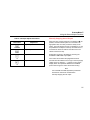
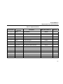
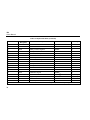
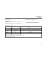
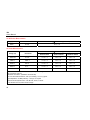
789 ProcessMeter™ Users Manual August 2002 Rev. 3, 3/13 © 2002-2013 Fluke Corporation, All rights reserved. Specifications are subject to change without notice. All product names are trademarks of their respective companies. LIMITED WARRANTY AND LIMITATION OF LIABILITY This Fluke product will be free from defects in material and workmanship for three years from the date of purchase. This warranty does not cover fuses, disposable batteries, or damage from accident, neglect, misuse, alteration, contamination, or abnormal conditions of operation or handling. Resellers are not authorized to extend any other warranty on Fluke’s behalf. To obtain service during the warranty period, contact your nearest Fluke authorized service center to obtain return authorization information, then send the product to that Service Center with a description of the problem. THIS WARRANTY IS YOUR ONLY REMEDY. NO OTHER WARRANTIES, SUCH AS FITNESS FOR A PARTICULAR PURPOSE, ARE EXPRESSED OR IMPLIED. FLUKE IS NOT LIABLE FOR ANY SPECIAL, INDIRECT, INCIDENTAL OR CONSEQUENTIAL DAMAGES OR LOSSES, ARISING FROM ANY CAUSE OR THEORY. Since some states or countries do not allow the exclusion or limitation of an implied warranty or of incidental or consequential damages, this limitation of liability may not apply to you. Fluke Corporation P.O. Box 9090 Everett, WA 98206-9090 U.S.A. 11/99 Fluke Europe B.V. P.O. Box 1186 5602 BD Eindhoven The Netherlands Table of Contents Title Introduction .................................................................................................................... How to Contact Fluke ..................................................................................................... Safety Information .......................................................................................................... How to Get Started ......................................................................................................... Getting Acquainted with the Meter ................................................................................. Measuring Electrical Parameters.................................................................................... Input Impedance ........................................................................................................ Ranges ...................................................................................................................... Testing Diodes........................................................................................................... Displaying Minimum, Maximum, and Average ........................................................... Using AutoHold.......................................................................................................... Compensating for Test Lead Resistance ................................................................... Using the Current Output Functions ............................................................................... Source Mode ............................................................................................................. Simulate Mode........................................................................................................... Producing a Steady mA Output ................................................................................. Manually Stepping the mA Output ............................................................................. Auto Ramping the mA Output .................................................................................... i Page 1 1 2 5 6 18 18 18 18 19 19 20 20 20 22 24 25 26 789 Users Manual Power-Up Options ......................................................................................................... Loop Power Supply Mode .............................................................................................. Battery Life..................................................................................................................... Maintenance .................................................................................................................. General Maintenance..................................................................................................... Calibration ................................................................................................................. Replacing a Fuse ...................................................................................................... If the Meter does not Work ........................................................................................ Replacement Parts and Accessories ............................................................................. Specifications ................................................................................................................. ii 27 29 31 31 31 31 34 34 35 39 List of Tables Table Title Page 1. 2. 3. 4. 5. 6. 7. 8. 9. 10. 11. 12. 13. International Symbols ............................................................................................................ Input/Output Jacks................................................................................................................. Rotary Function Switch Positions for Measurements ............................................................ Rotary Function Switch Positions for mA Output ................................................................... Rotary Function Switch Position for Loop Supply .................................................................. Pushbuttons .......................................................................................................................... Display................................................................................................................................... mA Output Adjust Pushbuttons ............................................................................................. mA Stepping Pushbuttons ..................................................................................................... mA Step Values ..................................................................................................................... Power-Up Options ................................................................................................................. Typical Alkaline Battery Life .................................................................................................. Replacement Parts ................................................................................................................ 4 7 9 11 11 13 16 25 26 26 28 31 37 iii 789 Users Manual iv List of Figures Figure Title Page 1. 2. 3. 4. 5. 6. 7. 8. 9. 10. 11. 12. Fluke 789 ProcessMeter........................................................................................................ Input/Output Jacks................................................................................................................. Rotary Function Switch Positions for Measurements ............................................................ Rotary Function Switch Positions for mA Output ................................................................... Pushbuttons .......................................................................................................................... Elements of the Display ......................................................................................................... Sourcing Current ................................................................................................................... Simulating a Transmitter........................................................................................................ Loop Power Voltage vs. Current ............................................................................................ Connections for Supplying Loop Power................................................................................. Replacing the Batteries and Fuses ........................................................................................ Replacement Parts ................................................................................................................ 5 6 8 10 12 15 21 23 29 30 33 36 v 789 Users Manual vi ProcessMeter Introduction How to Contact Fluke Warning Read “Safety Information” before using the meter. The Fluke 789 ProcessMeter (referred to as “the meter”) is a handheld, battery-operated tool for measuring electrical parameters, supplying steady or ramping current to test process instruments, and providing a > 24 V loop power supply. It has all the features of a digital multimeter, plus current output capability. If the meter is damaged or something is missing, contact the place of purchase immediately. Contact a Fluke distributor for information about DMM (digital multimeter) accessories. To order replacement parts or spares, see Table 13 near the end of this manual. To contact Fluke, call one of the following telephone numbers: • Technical Support USA: 1-800-44-FLUKE (1-800-4435853) • Calibration/Repair USA: 1-888-99-FLUKE (1-888-9935853) • Canada: 1-800-36-FLUKE (1-800-363-5853) • Europe: +31 402-675-200 • Japan: +81-3-6714-3114 • Singapore: +65-6799-5566 • Anywhere in the world: +1-425-446-5500 Or, visit Fluke's website at www.fluke.com. To register your product, visit http://register.fluke.com. 1 789 Users Manual • Inspect the test leads for damaged insulation or exposed metal. Check test lead continuity. Replace damaged test leads before using the meter. • Do not use the meter if it operates abnormally. Protection may be impaired. When in doubt, have the meter serviced. • Do not operate the meter around explosive gas, vapor, or dust. • Do not use in a damp or wet environment. • Use only type AA batteries, properly installed in the meter case, to power the meter. To prevent possible electrical shock, fire, or personal injury: • When servicing the meter, use only specified replacement parts. • Read “Safety Information” before using the meter. • • Do not use the meter if it is damaged. Before using the meter, inspect the case. Look for cracks or missing plastic. Pay particular attention to the insulation surrounding the connectors. Use caution when working above 30 V ac rms, 42 V ac pk, or 60 V dc. Such voltages pose a shock hazard. • When using the probes, keep fingers behind the finger guards on the probes. • Connect the common test lead before connecting the live test lead. When disconnecting test leads, disconnect the live test lead first. To view, print, or download the latest manual supplement, visit http://us.fluke.com/usen/support/manuals. Safety Information A Warning identifies conditions and procedures that are dangerous to the user. A Caution identifies conditions and procedures that can cause damage to the Product or the equipment under test. International symbols used on the meter and in this manual are explained in Table 1. Warning • Make sure the battery door is closed and latched before operating the meter. • Remove test leads from the meter before opening the battery door. 2 ProcessMeter™ Safety Information • Do not use AutoHold to determine if dangerous voltage is present. AutoHold will not capture unstable or noisy readings. • To avoid false readings, which could lead to possible electric shock or personal injury, replace the battery as soon as the battery indicator () appears. • Remove test leads from the meter before opening the battery door. • Close and latch the battery door before using the meter. • To avoid personal injury or damage to the meter, use only the specified replacement fuse, 440 mA 1000 V fast-blow, Fluke PN 943121. • Do not exceed the Measurement Category (CAT) rating of the lowest rated individual component of a product, probe, or accessory. • Do not use the TL175 or TP175 test probes in CAT III or CAT IV environments without the probe tip fully extended and correct category rating visible in the window. • When the TL175 is used with instruments or other accessories, the lowest category rating of the combination applies. One exception is when the probe is used with the AC172 or AC175. 3 789 Users Manual Table 1. International Symbols Symbol Risk of danger. Important information. See Manual. Symbol Meaning Hazardous voltage Conforms to European Union directives Meets Underwriters’ Laboratories safety requirements Inspected and licensed by TÜV Product Services Conforms to relevant North American Safety Standards Alternating current Direct current Battery Conforms to relevant South Korean EMC Standards Conforms to relevant Australian Standards Earth ground Fuse Double insulated CAT II Measurement Category II is applicable to test and measuring circuits connected directly to utilization points (socket outlets and similar points) of the low-voltage MAINS installation. CAT III Measurement Category III is applicable to test and measuring circuits connected to the distribution part of the building’s low-voltage MAINS installation. CAT IV Measurement Category IV is applicable to test and measuring circuits connected at the source of the building’s low-voltage MAINS installation. 4 Meaning This product complies with the WEEE Directive (2002/96/EC) marking requirements. The affixed label indicates that you must not discard this electrical/electronic product in domestic household waste. Product Category: With reference to the equipment types in the WEEE Directive Annex I, this product is classed as category 9 "Monitoring and Control Instrumentation" product. Do not dispose of this product as unsorted municipal waste. Go to Fluke’s website for recycling information. ProcessMeter™ How to Get Started How to Get Started If familiar with the Fluke 80 Series DMM, read “Using the Current Output Functions,” review the tables and figures in “Getting Acquainted with the Meter,” and begin using the meter. Display 789 PROCESSMETER If unfamiliar with Fluke 80 Series DMMs, or DMMs in general, read “Measuring Electrical Parameters” in addition to the sections referenced in the previous paragraph. The sections following “Using the Current Output Functions” contain information about the power-up options, and battery and fuse replacement instructions. Later, use the Quick Reference Guide to refresh your memory about the various functions and features that can be used. Pushbuttons 100% MIN MAX RANGE HOLD SpanCheck %STEP COARSE FINE 0% Rotary Switch REL Hz mV mA A V V mA mA OFF 250 HART LOOP POWER mA A mA COM V Input/Output Jacks CAT IV 600 V anw014f.eps Figure 1. Fluke 789 ProcessMeter 5 789 Users Manual Getting Acquainted with the Meter To become familiar with the features and functions of the meter, study the following figures and tables. • Figure 2 and Table 2 describe the input/output jacks. • Figure 3 and Table 3 describe the input functions of the first six rotary function switch positions. A 1 mA • Figure 4 and Tables 4 and 5 describe the output functions of the last three rotary function switch positions. • Figure 5 and Table 6 describe the functions of the pushbuttons. • Figure 6 and Table 7 explain what all the elements of the display indicate. V COM 3 CAT IV 600 V 4 2 anw001f.eps Figure 2. Input/Output Jacks 6 ProcessMeter™ Getting Acquainted with the Meter Table 2. Input/Output Jacks Item Jack Measurement Functions Source Current Function Ac Input for current to 440 mA continuous. (1 A for up to 30 seconds.) Fused with a 440 mA fuse. Output for dc current to 24 mA. Output for loop power supply. mA d Input for current to 30 mA. Fused with a 440 mA fuse. Common for dc current output to 24 mA. Common for loop power supply. V COM Simulate Transmitter Function Output for transmitter simulation to 24 mA. (Use in series with an external loop supply.) Input for voltage to 1000 V, Ω, continuity, and diode test. Common for all measurements. Common for transmitter simulation to 24 mA. (Use in series with an external loop supply.) 7 789 Users Manual 5 4 mV 3 V 6 mA A 2 1 V mA OFF mA 250 HART LOOP POWER mA anw002f.eps Figure 3. Rotary Function Switch Positions for Measurements 8 ProcessMeter™ Getting Acquainted with the Meter Table 3. Rotary Function Switch Positions for Measurements No. Position OFF S Function(s) Meter off Default: Measure ac V h M Selects a MIN, MAX, or AVG action R Selects a fixed range (hold 1 second for auto range) H Toggles AutoHold r Toggles relative reading (sets a relative zero point) Default: Measure dc V Same as above Frequency counter T Pushbutton Actions h U Frequency counter Default: Measure dc mV Same as above h Frequency counter V Default: Measure Ω Same as above, except diode test has only one range G for continuity J (Blue) D test W High test lead in cA: Measure A dc J (Blue) selects ac Same as above, except there is only one range for each input jack position, 30 mA or 1 A High test lead in dmA: Measure mA dc 9 789 Users Manual mV V mA A V 1 mA 2 mA OFF 3 250 HART LOOP POWER mA anw008f.eps Figure 4. Rotary Function Switch Positions for mA Output 10 ProcessMeter™ Getting Acquainted with the Meter Table 4. Rotary Function Switch Positions for mA Output No. Position OUTPUT X Default Function Test leads in SOURCE: Source 0 % mA % STEP X or W: Adjusts output up or down to the next 25 % step COARSE X or W: Adjusts output up or down 0.1 mA Test leads in SIMULATE: Sink 0 % mA OUTPUT Y monp Pushbutton Actions Test leads in SOURCE: Source repeating 0 % -100 %-0 % slow ramp (m) Test leads in SIMULATE: Sink repeating 0 % -100 %-0 % slow ramp (m) FINE X or W: Adjusts output up or down 0.001 mA sets output to 0 % sets output to 100 % J (Blue) cycles through: • Fast repeating 0 % -100 % - 0 % ramp (o on display) • Slow repeating 0 % -100 % - 0 % ramp in 25 % steps (n on display) • Fast repeating 0 % -100 % - 0 % ramp in 25 % steps ( pon display) • Slow repeating 0 % -100 % - 0 % ramp (m on display) Table 5. Rotary Function Switch Position for Loop Supply No. Position 250 mA HART LOOP POWER Default Function Pushbutton Actions Test leads in SOURCE: J (Blue) cycles through: Supply > 24 V loop power, measure mA • 250 Ω series resistor for HART communication switched in • 250 Ω series resistor switched out 11 789 Users Manual 4 5 6 3 100% MIN MAX RANGE HOLD SpanCheck %STEP COARSE FINE 0% REL Hz 2 7 10 9 1 8 anw003f.eps Figure 5. Pushbuttons 12 ProcessMeter™ Getting Acquainted with the Meter Table 6. Pushbuttons No. Pushbutton K Span Check Function(s) Toggles the backlight (low, high, and off) mA Output: Adjusts mA output to 0 % value (4 mA or 0 mA) D Span Check E % STEP F COARSE M R H FINE mA Output: Sets mA output to 100 % value (20 mA) Measuring: Selects a MIN, MAX, or AVG action mA Output: Adjusts mA output up to the next higher 25 % step Measuring: Selects a fixed range (hold for 1 second for auto range) mA Output: Adjusts output up 0.1 mA Measuring: Toggles AutoHold, or in MIN MAX recording, suspends recording mA Output: Adjusts output up 0.001 mA 13 789 Users Manual Table 6. Pushbuttons (cont.) No. G H Pushbutton FINE h J (BLUE) (alternate function) Function(s) Measuring: Toggles between frequency counter and voltage measurement functions mA Output: Adjusts output down 0.001 mA Rotary function switch in Wposition and test lead plugged into Ac jack: Toggles between ac and dc ampere measure Rotary function switch in V position: Toggles diode test function (D) Rotary function switch in OUTPUT Ymonp position: cycles through • Slow repeating 0 % -100 % - 0 % ramp (m on display) • Fast repeating 0 % -100 % - 0 % ramp (o on display) • Slow repeating 0 % -100 % - 0 % ramp in 25 % steps (p on display) • Fast repeating 0 % - 100 % - 0 % ramp in 25 % steps (pon display) Rotary function switch in loop supply position • I COARSE J % STEP r G 14 Switch in/out 250 Ω series resistor Measuring: Toggles relative reading (sets a relative zero point) mA Output: Adjusts output down 0.1 mA Measuring: Toggles between Ω measure and continuity functions mA Output: Adjusts mA output down to the next lower 25 % step ProcessMeter™ Getting Acquainted with the Meter 6 7 8 9 10 11 12 5 13 4 3 14 15 2 1 17 16 anw004f.eps Figure 6. Elements of the Display 15 789 Users Manual Table 7. Display No. Element % (Percentage display) OUTPUT S Lights in continuity function D Lights when dangerous voltage is present E Lights when relative reading is on F b G q H Numerals Show the input or output value IK lI Lights when AutoHold is on J D Lights in diode test function K I Lights when MIN MAX recording is held L N MAX MINAVG 16 Meaning Shows the mA measured value or output level in %, in a 0-20 mA or 4-20 mA scale (change scales with power-up option) Lights when mA output (source or simulate) is active Lights when the battery is low Lights when the meter is transmitting or receiving over the IR port MIN MAX recording status indicators: N - MIN MAX recording is on MAX - the display is showing the maximum-recorded value MIN - the display is showing the minimum-recorded value AVG - the display is showing the average value since starting recording (up to about 40 hours continuous recording time) ProcessMeter™ Getting Acquainted with the Meter Table 7. Display (cont.) No. Element M mA, DC, mV, AC, M or kΩ, kHz N Auto Range Manual Range 400100030 Meaning Show the input or output units and multipliers associated with the numerals Range status indicators: Auto Range - autoranging is on Manual Range - the range is fixed The number plus the unit and multiplier indicate the active range. mV O mo np One of these lights in mA ramping or step output (rotary function switch position Ymo np): m - slow continuous 0 % - 100 % - 0 % ramping (40 seconds) o - fast continuous 0 % - 100 % - 0 % ramping (15 seconds) n - slow ramp in 25 % steps (15 seconds/step) p - fast ramp in 25 % steps (5 seconds/step) P 250 Ω HART Q Loop Power Lights when 250 Ω series resistance is switched in Lights when in loop supply mode 17 789 Users Manual Measuring Electrical Parameters The proper sequence for taking measurements follows: 1. Plug the test leads into the appropriate jacks 2. Set the rotary function switch to the desired function 3. Touch the probes to the test points 4. View the results on the LCD display Input Impedance For the voltage measurement functions, input impedance is 10 MΩ. See "Specifications" for more information. Ranges A measurement range determines the highest value and resolution at which the meter can measure. Most meter measurement functions have more than one range (see "Specifications"). The meter normally selects the lowest range that will measure the applied input signal (Auto Range showing on the display). Press R to lock the range. Each time R is pressed, the meter selects the next higher range. At the highest range, it returns to the lowest range. If the range is locked, the meter resumes auto ranging when it is changed to another measurement function or when R is pressed and held for 1 second. Testing Diodes To test a single diode: 1. Insert the red test lead into the Vjack and black test lead into the COM jack. 2. Set the rotary function switch to V. 3. Press J (Blue) so that the D symbol is on the display. 4. Touch the red probe to the anode and the black probe to the cathode (side with band or bands). The meter should indicate the appropriate diode voltage drop. 5. Reverse the probes. The meter displays OL, indicating a high impedance. Make sure the correct range is selected: • If the range is too low, the display shows OL (overload). • If the range is too high, the meter will not be displaying its most precise measurement. 18 ProcessMeter™ Measuring Electrical Parameters 6. The diode is good if it passes the tests in steps 4 and 5. Displaying Minimum, Maximum, and Average MIN MAX recording stores the lowest and highest measurements, and maintains the average of all measurements. Press M to turn on MIN MAX recording. Readings are stored until the meter is turned off, switched to another measurement or source function, or MIN MAX is turned off. The beeper sounds when a new maximum or minimum is recorded. Auto power-off is disabled and auto ranging is turned off during MIN MAX recording. Press M again to cycle through the MAX, MIN, and AVG displays. Press and hold M for 1 second to erase stored measurements and exit. Using AutoHold Note MIN MAX recording must be off to use AutoHold. ! Warning To avoid possible electric shock, do not use AutoHold to determine if dangerous voltage is present. AutoHold will not capture unstable or noisy readings. Activate AutoHold to freeze the meter's display on each new stable reading (except in the frequency counter mode). Press H to activate AutoHold. This feature allows measurements to be taken in situations in which it is difficult to look at the display. The meter beeps and updates the display with each new stable reading. If MIN MAX recording is on continuously for over 40 hours, minimum and maximum readings are still recorded, but the displayed average no longer changes. In MIN MAX recording, press H to suspend recording; press H again to resume recording. 19 789 Users Manual Compensating for Test Lead Resistance Use the relative reading feature (Q on the display) to set the present measurement as a relative zero. A common use for this feature is to compensate for test lead resistance when measuring ohms. Select the Ω measure function, touch the test leads together, and then press r. Until r is pressed again, or the meter is switched to another measurement or source function, the readings on the display will subtract the lead resistance. Using the Current Output Functions The meter provides steady, stepped, and ramped current output for testing 0-20 mA and 4-20 mA current loops. Choose source mode, in which the meter supplies the current, simulate mode, in which the meter regulates 20 current in an externally powered current loop, or loop supply mode, where the meter powers an external device and measures the loop current. Source Mode Source mode is selected automatically by inserting the test leads into the SOURCE + and − jacks as shown in Figure 7. Use source mode whenever it is necessary to supply current into a passive circuit such as a current loop with no loop supply. Source mode depletes the battery faster than simulate mode, so use simulate mode whenever possible. The display looks the same in source and simulate modes. The way to tell which mode is in use is to see which pair of output jacks is in use. ProcessMeter™ Using the Current Output Functions 789 PROCESSMETER 40 20 0 100% MIN MAX RANGE HOLD SpanCheck %STEP COARSE FINE 0% REL mV 60 80 100 Hz mA A V V mA mA OFF 250 HART LOOP POWER mA A mA V COM CAT IV 600 V anw010f.eps Figure 7. Sourcing Current 21 789 Users Manual Simulate Mode Changing the Current Span Simulate mode is so named because the meter simulates a current loop transmitter. Use simulate mode when an external dc voltage of 15 to 48 V is in series with the current loop under test. The meter’s current output span has two settings (with overrange to 24 mA): Caution Set the rotary function switch to one of the mA output settings BEFORE connecting the test leads to a current loop. Otherwise, a low impedance from the other rotary function switch positions could be presented to the loop, causing up to 35 mA to flow in the loop. Simulate mode is selected automatically by inserting the test leads into the SIMULATE + and − jacks as shown in Figure 8. Simulate mode conserves battery life, so use it instead of source mode whenever possible. The display looks the same in source and simulate modes. The way to tell which mode is in use is to see which pair of output jacks is in use. 22 • 4 mA = 0 %, 20 mA = 100 % (factory default) • 0 mA = 0 %, 20 mA = 100 % To find out which span is selected, short the OUTPUT SOURCE + and − jacks, turn the rotary function switch to OUTPUT [ mA, and observe the 0 % output level. To toggle and save the current output span in nonvolatile memory (retained when the power is turned off): 1. Turn off the meter. 2. Hold down R while turning the meter on. 3. Wait at least 2 seconds, then release R. ProcessMeter™ Using the Current Output Functions dc V Power Supply 789 PROCESSMETER 40 COM +24V 20 0 100% MIN MAX RANGE HOLD SpanCheck %STEP COARSE FINE 0% REL mV 60 80 100 Hz mA A V V mA OFF mA 250 HART LOOP POWER mA A mA V COM CAT IV 600 V anw011f.eps Figure 8. Simulating a Transmitter 23 789 Users Manual Producing a Steady mA Output When the rotary function switch is in the OUTPUT [ mA position, and the OUTPUT jacks are connected to an appropriate load, the meter produces a steady mA dc output. The meter begins sourcing or simulating 0 %. Use the pushbuttons to adjust the current as shown in Table 8. Select either sourcing or simulating by choosing the SOURCE or SIMULATE output jacks. 24 If the meter cannot deliver the programmed current because the load resistance is too high or the loop supply voltage is too low, dashes (-----) appear on the numeric display. When the impedance between the SOURCE jacks is low enough, the meter will resume sourcing. Note The STEP pushbuttons described Table 9 are available when the meter is producing a steady mA output. The STEP pushbuttons go to the next multiple of 25 %. ProcessMeter™ Using the Current Output Functions Table 8. mA Output Adjust Pushbuttons Pushbutton X R COARSE X M FINE FINE Adjustment Adjusts up 0.1 mA Adjusts up 0.001 mA Adjusts down 0.001 mA h W COARSE r W Adjusts down 0.1 mA Manually Stepping the mA Output When the rotary function switch is in the OUTPUT [ mA position, and the OUTPUT jacks are connected to an appropriate load, the meter produces a steady mA dc output. The meter begins sourcing or simulating 0 %. Use the pushbuttons to step the current up and down in 25 % increments as shown in Table 9. See Table 10 for mA values at each 25 % step. Select either sourcing or simulating by choosing the SOURCE or SIMULATE output jacks. If the meter cannot deliver the programmed current because the load resistance is too high or the loop supply voltage is too low, dashes (-----) appear on the numeric display. When the impedance between the SOURCE jacks is low enough, the meter will resume sourcing. Note The COARSE and FINE adjustment pushbuttons described in Table 8 are available when manually stepping the mA output. 25 789 Users Manual Table 9. mA Stepping Pushbuttons Pushbutton Adjustment X M Adjusts up to the next higher 25 % step G Adjusts down to the next lower 25 % step % STEP % STEP W Span Check Span Check Sets to 100 % value Sets to 0 % value Table 10. mA Step Values Value (for each span setting) Step 4 to 20 mA 0 to 20 mA 0% 4.000 mA 0.000 mA 25 % 8.000 mA 5.000 mA 50 % 12.000 mA 10.000 mA 75 % 16.000 mA 15.000 mA 100 % 20.000 mA 20.000 mA 125 % 24.000 mA 120 % 24.000 mA Auto Ramping the mA Output Auto ramping gives the ability to continuously apply a varying current stimulus from the meter to a transmitter, while hands remain free to test the response of the transmitter. Select either sourcing or simulating by choosing the SOURCE or SIMULATE jacks. 26 ProcessMeter™ Power-Up Options When the rotary function switch is in the OUTPUT Ymonp position, and the output jacks are connected to an appropriate load, the meter produces a continuously repeating 0 % - 100 % - 0 % ramp in a choice of four ramp waveforms: m 0 % - 100 % - 0 % 40-second smooth ramp (default) o 0 % - 100 % - 0 % 15-second smooth ramp n 0 % - 100 % - 0 % Stair-step ramp in 25 % steps, pausing 15 seconds at each step. Steps listed in Table 10. p 0 % - 100 % - 0 % Stair-step ramp in 25 % steps, pausing 5 seconds at each step. Steps are listed in Table 10. Power-Up Options To select a power-up option, hold down the pushbutton shown in Table 11 while turning the rotary function switch from OFF to any on position. Wait 2 seconds before releasing the pushbutton after powering up the meter. The meter beeps to acknowledge the power-up option. Only the setting for current span is retained when the power is turned off. The other options have to be repeated for each operating session. Holding down more than one pushbutton can activate more than one power-up option. The ramp times are not adjustable. Press J (Blue) to cycle through the four waveforms. Note At any time during auto ramping, the ramp can be frozen simply by moving the rotary function switch to the [ mA position. Then the COARSE, FINE, and % STEP adjust pushbuttons can be used to make adjustments. 27 789 Users Manual Table 11. Power-Up Options Option Pushbutton Default Action Taken Change current span 0 % setting R Remembers last setting Toggles between 0 - 20 mA and 4 - 20 mA range Disable beeper G Enabled Disables beeper Disable auto power-off J (Blue) Enabled Disables the feature that turns off the meter power after 30 minutes of inactivity. Auto power off is disabled regardless of this option if MIN MAX recording is on. Display test/show firmware version H Disabled Display HOLD (as long as button is pushed), then shows firmware version. 28 ProcessMeter™ Loop Power Supply Mode Loop Power Supply Mode The meter supplies loop power at a nominal 24 V dc. An internal series resistance of 250 Ω can be switched in for communication with HART and other smart devices by pressing J (Blue). Pressing J (Blue) again switches out this internal resistance. When loop power is enabled, the meter is configured to measure mA and > 24 V dc is sourced between the mA and A jacks. The mA jack is the common and the A jack is at > 24 V dc. Connect the meter in series with the instrument current loop as Figure 10 shows. 30 Voltage (V) The Loop Power Supply Mode can be used for powering up a process instrument (transmitter). While in Loop Power Mode, the meter acts like a battery. The process instrument regulates the current. At the same time, the meter measures the current that the process instrument is drawing. 32 28 26 24 22 20 0 4 8 12 16 20 24 Current (mA) Loop voltage w/ 250 Loop voltage w/o 250 anw020f.eps Figure 9. Loop Power Voltage vs. Current 29 789 Users Manual 789 PROCESSMETER 100% MIN MAX RANGE HOLD SpanCheck %STEP COARSE FINE 0% REL mV Hz mA A V TEST DC PWR – ++ – V mA OFF mA Red 250 HART LOOP POWER mA A mA + – V COM CAT IV 600 V Black anw009f.eps Figure 10. Connections for Supplying Loop Power 30 ProcessMeter™ Battery Life Maintenance Battery Life Warning To avoid false readings, which could lead to possible electric shock or personal injury, replace the battery as soon as the battery indicator (b) appears. Table 12 shows typical alkaline battery life. To preserve battery life: • • • • Use current simulation instead of sourcing when possible. Avoid using the backlight. Do not disable the automatic power-off feature. Turn the meter off when not in use. Table 12. Typical Alkaline Battery Life Meter Operation Measuring any parameter Simulating Current Sourcing 12 mA into 500 Ω This section provides some basic maintenance procedures. Repair, calibration, and servicing not covered in this manual must be performed by qualified personnel. For maintenance procedures not described in this manual, contact a Fluke Service Center. General Maintenance Periodically wipe the case with a damp cloth and detergent; do not use abrasives or solvents. Calibration Calibrate the meter once a year to ensure that it performs according to its specifications. Contact a Fluke Service Center for instructions. Hours 140 140 10 31 789 Users Manual Replacing the Batteries 2. With a standard blade hand screwdriver, turn each battery door screw counterclockwise so that the slot is parallel with the screw picture molded into the case. 3. Lift off the battery door. 4. Remove the meter's batteries. 5. Replace with four new AA alkaline batteries. 6. Reinstall the battery door and tighten screws. ! Warning To avoid electrical shock: • Remove test leads from the meter before opening the battery door. • Close and latch the battery door before using the meter. Replace the batteries as follows. Refer to Figure 11. Use four AA alkaline batteries. 1. 32 Remove the test leads and turn the meter OFF. ProcessMeter™ General Maintenance F1 F2 anw037.eps Figure 11. Replacing the Batteries and Fuses 33 789 Users Manual If a fuse is blown, replace it as follows. Refer to Figure 11 as necessary: Replacing a Fuse ! Warning To avoid personal injury or damage to the meter, use only the specified replacement fuse, 440 mA 1000 V fast-blow, Fluke PN 943121. Both current input jacks are fused with separate 440 mA fuses. To determine if a fuse is blown: Turn the rotary function switch to 2. Plug the black test lead into COM, and the red test lead into the A c input. Using an ohmmeter, check the resistance between the meter test leads. If the resistance is about 1 Ω, the fuse is good. An open reading means that fuse F1 is blown. 4. Move red test lead to . 5. Using an ohmmeter, check the resistance between the meter test leads. If the resistance is about 14 Ω, the fuse is good. An open means that fuse F2 is blown. 34 Remove the test leads from the meter and turn the meter OFF. 2. With a standard blade hand screwdriver, turn each battery door screw counterclockwise so that the slot is parallel with the screw picture molded into the case. 3. Remove either fuse by gently prying one end loose, then sliding the fuse out of its bracket. 4. Replace the blown fuse(s). 5. Replace the battery access door. Secure the door by turning the screws one-quarter turn clockwise. W. 1. 3. 1. If the Meter does not Work • Examine the case for physical damage. If there is damage, make no further attempt to use the meter, and contact a Fluke Service Center. • Check the battery, fuses, and test leads. • Review this manual to make sure you are using the correct jacks and rotary function switch position. ProcessMeter™ Replacement Parts and Accessories If the meter still does not work, contact a Fluke Service Center. If the meter is under warranty, it will be repaired or replaced (at Fluke’s option) and returned at no charge. See the Warranty on the back of the title page for terms. If the warranty has lapsed, the meter will be repaired and returned for a fixed fee. Contact a Fluke Service Center for information and price. Replacement Parts and Accessories ! Warning To avoid personal injury or damage to the meter, use only the specified replacement fuse, 440 mA 1000 V fast-blow, Fluke PN 943121. Note When servicing the meter, use only the replacement parts specified here. Replacement parts and some accessories are shown in Figure 12 and listed in Table 13. Many more DMM accessories are available from Fluke. For a catalog, contact the nearest Fluke distributor. To find out how to order parts or accessories use the telephone numbers or addresses shown in "Contacting Fluke". 35 789 Users Manual 1 2 3 17 30 18 16 8 4 15 5 29 26 14 27 13 6 28 19 25 24 7 20 23 12 21 22 9 11 10 anw005f.eps Figure 12. Replacement Parts 36 ProcessMeter™ Replacement Parts and Accessories Table 13. Replacement Parts Item Number Reference Designator Description Fluke PN or Model no. Quantity MP14 Knob Assembly 658440 1 MP1 Top Case with Lens Protector 1622855 1 MP8 Decal, Top Case 1623923 1 D MP6 Keypad 1622951 1 E MP5 Top Shield 1622924 1 F MP47 Top Shield Contact 674853 1 G MP4 Contact Housing 1622913 1 H MP28-31 RSOB Contact 1567683 4 I F1, F2 Fuse, 440 mA, 1000 V fast-blow 943121 2 J H7,8 PCB Screw 832220 2 K MP9 Bottom Shield 1675171 1 L MP12 IR Lens 658697 1 M MP40,41 LCD Connectors, Elastomeric 1641965 2 N MP7 Backlight/Bracket 1622960 1 O P1 LCD Display 1883431 1 P MP3 Mask 1622881 1 37 789 Users Manual Table 13. Replacement Parts (continued) Item Number Reference Designator Description Q R S T U V W X Y Z a b c d MP50 Shock Absorber MP11 MP20 BT1-4 - Fluke PN or Model no. Quantity 878983 1 Bottom Case 659042 1 Battery Contact, Negative 658382 1 Battery, 1.5 V, 0-15 mA, AA Alkaline 376756 4 H1-2 Fasteners, Battery/Fuse Access Door 948609 2 MP13 Tilt-Stand 659026 1 MP15 Accessory Mount with Probe Holders 658424 1 MP2 Access Door, Battery/Fuse 1622870 1 MP46 Shock Absorber 674850 1 MP16-18 Battery Contacts Dual 666435 3 MP19 Battery Contact, Positive 666438 1 H3-6 Case Screws 1558745 4 MP21 Calibration Label 948674 1 MP22 Calibration Keypad 658689 1 Not shown Test Leads variable[1] [1] 1 (set of 2) - Not shown Alligator Clips variable 1 (set of 2) - Not shown 789 Quick Reference 4276679 1 Not shown CD-ROM (Contains Users Manual) 1636493 1 [1] 38 See www.fluke.com for more information about the test leads and alligator clips available for your region. ProcessMeter™ Specifications The standard specification interval is 1 year. Specifications All specifications apply from +18 °C to +28 °C unless stated otherwise. All specifications assume a 5-minute warm-up period. Note “Counts” refers to the number of increments or decrements of the least significant digit. DC Volts Measurement Range (V dc) Resolution Accuracy, ±(% of Reading + Counts) 4.000 0.001 V 0.1 % + 1 40.00 0.01 V 0.1 % + 1 400.0 0.1 V 0.1 % + 1 1000 1V 0.1 % + 1 Input impedance: 10 MΩ (nominal), < 100 pF Normal mode rejection ratio: > 60 dB at 50 Hz or 60 Hz Common mode rejection ratio: > 120 dB at dc, 50 Hz, or 60 Hz Overvoltage protection: 1000 V 39 789 Users Manual DC Millivolts Measurement Range (mV dc) 400.0 Accuracy, ±(% of Reading + Counts) Resolution 0.1 mV 0.1 % + 2 AC Volts Measurement Range (ac) Resolution Accuracy, ±(% of Reading + Counts) 50 Hz to 60 Hz 200 Hz to 500 Hz 400.0 mV 0.1 mV 0.7 % + 4 1.2 % + 4 7.0 % + 4 4.000 V 0.001 V 0.7 % + 2 1.2 % + 4 7.0 % + 4 40.00 V 0.01 V 0.7 % + 2 1.2 % + 4 7.0 % + 4 400.0 V 0.1 V 0.7 % + 2 1.2 % + 4 7.0 % + 4 1000 V 1V 0.7 % + 2 1.2 % + 4 7.0 % + 4 Specifications are valid from 5 % to 100 % of amplitude range. AC conversion: true rms Maximum crest factor: 3 (between 50 and 60 Hz) For non-sinusoidal waveforms, add ±(2 % reading + 2 % f.s.) typical Input impedance: 10 MΩ (nominal), < 100 pF, ac-coupled Common mode rejection ratio: > 60 dB at dc, 50 Hz, or 60 Hz In an RF field of 3 V/m, add 0.25 % of range 40 45 Hz to 200 Hz ProcessMeter™ Specifications AC Current Measurement Range 45 Hz to 2 kHz Resolution 1.000 A (Note) 0.001 A Accuracy, ±(% of Reading + Counts) 1%+2 Typical Burden Voltage 1.5 V/A Note: 440 mA continuous, 1 A 30 seconds maximum Specifications are valid from 5 % to 100 % of amplitude range. AC conversion: true rms Maximum crest factor: 3 (between 50 and 60 Hz) For non-sinusoidal waveforms, add ±( 2 % reading + 2 % f.s.) typical Overload protection 440 mA, 1000 V fast-blow fuse DC Current Measurement Typical Burden Voltage Resolution Accuracy, ±(% of Reading + Counts) 30.000 mA 0.001 mA 0.05 % + 2 14 mV/mA 1.000 A (Note) 0.001 A 0.2 % + 2 1.5 V/A Range Note: 440 mA continuous, 1 A 30 seconds maximum Overload protection: 440 mA, 1000 V fast-blow fuse In an RF field of 3 V/m, in 30.000 mA range, add 0.14 % of range 41 789 Users Manual Ohms Measurement Range Resolution Accuracy, ±(% of Reading + Counts) 400.0 Ω 0.1 Ω 220 μA 0.2 % + 2 4.000 kΩ 0.001 kΩ 60 μA 0.2 % + 1 40.00 kΩ 0.01 kΩ 6.0 μA 0.2 % + 1 400.0 kΩ 0.1 kΩ 600 nA 0.2 % + 1 4.000 MΩ 0.001 MΩ 220 nA 0.35 % + 3 40.00 MΩ 0.01 MΩ 22 nA 2.5 % + 3 Overload protection: 1000 V Open circuit voltage: <3.9 V 42 Measurement Current ProcessMeter™ Specifications Frequency Counter Accuracy Range Accuracy, ±(% of Reading + Counts) Resolution 199.99 Hz 0.01 Hz 0.005 % + 1 1999.9 Hz 0.1 Hz 0.005 % + 1 19.999 kHz 0.001 kHz 0.005 % + 1 Display updates 3 times/second at > 10 Hz Frequency Counter Sensitivity Minimum Sensitivity (rms Sinewave) 5 Hz to 5 kHz* Input Range AC DC (approximate trigger level 5 % of full scale) 400 mV 150 mV (50 Hz to 5 kHz) 150 mV 4V 1V 1V 40 V 4V 4V 400 V 40 V 40 V 1000 V 400 V 400 V *Usable 0.5 Hz to 20 kHz with reduced sensitivity. 106 VHz max 43 789 Users Manual Diode Test and Continuity Test Diode test indication ........................................... Displays voltage drop across device, 2.0 V full scale. Nominal test current 0.2 mA at 0.6 V. Accuracy ±(2 % + 1 count). Continuity test indication ..................................... Continuous audible tone for test resistance <100 Ω Open circuit voltage ............................................ 2.9 V Short circuit current ............................................. 220 μA typical Overload protection ............................................. 1000 V rms Loop Power Supply Voltage ................................. 24 V, Short Circuit protected DC Current Output Source mode: Span .............................................................. 0 mA or 4 mA to 20 mA, with overrange to 24 mA [1] Accuracy ....................................................... 0.05 % of span Compliance voltage ...................................... 28 V with battery voltage >~4.5 V [1] In an RF field of 3 V/m, add 0.32 % of span Simulate Mode Span .............................................................. 0 mA or 4 mA to 20 mA, with overrange to 24 mA 1 Accuracy ....................................................... 0.05 % of span Loop voltage ................................................. 24 V nominal, 48 V maximum, 15 V minimum Compliance voltage ...................................... 21 V for 24 V supply Burden voltage .............................................. <3 V 44 ProcessMeter™ Specifications General Specifications Maximum voltage applied between any jack and earth ground .................................... 1000 V Battery Type ........................................................... 1.5 V, 0-15 mA, AA, Alkaline Storage temperature ............................................. -40 °C to 60 °C Operating temperature .......................................... -20 °C to 55 °C Operating altitude .................................................. 2000 meters maximum 6 Frequency Overload Protection ....................... 10 V Hz max Temperature coefficient ........................................ 0.05 x specified accuracy per °C for temperatures <18 °C or >28 °C 0.1 x specified accuracy per °C for temperatures <18 °C or >28 °C Relative humidity ................................................... 95 % up to 30 °C, 75 % up to 40 °C, 45 % up to 50 °C, and 35 % up to 55 °C Vibration ................................................................. Random 2g, 5 to 500 Hz Shock ...................................................................... 1 meter drop test Power requirements .............................................. Four AA batteries (alkaline recommended) Size ......................................................................... 10.0 cm X 20.3 cm X 5.0 cm (3.94 in X 8.00 in X 1.97 in) Weight .................................................................... 610 g (1.6 lb) Safety ...................................................................... IEC 61010-1: 600 V CAT IV / 1000 V CAT III, Pollution Degree 2 Electromagnetic Environment.............................. IEC 61326-1: Portable Electromagnetic Compatibility ............................. Accuracy for all ProcessMeter functions is not specified in RF field > 3V/m [1] Applies to use in Korea only ................................ Class A Equipment (Industrial Broadcasting & Communication Equipment [1] This product meets requirements for industrial (Class A) electromagnetic wave equipment and the seller or user should take notice of it. This equipment is intended for use in business environments and not to be used in homes. 45 789 Users Manual 46