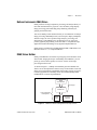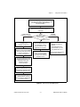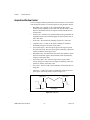
1
IMAQ
™
IMAQ PCI/PXI™-1408
User Manual
High-Quality Monochrome Image Acquisition Boards
for PCI, PXI, and CompactPCI Bus
IMAQ PCI/PXI-1408 User Manual
October 1999 Edition
Part Number 321325D-01
Worldwide Technical Support and Product Information
www.ni.com
National Instruments Corporate Headquarters
11500 North Mopac Expressway Austin, Texas 78759-3504 USA Tel: 512 794 0100
Worldwide Offices
Australia 03 9879 5166, Austria 0662 45 79 90 0, Belgium 02 757 00 20, Brazil 011 284 5011,
Canada (Calgary) 403 274 9391, Canada (Ontario) 905 785 0085, Canada (Québec) 514 694 8521,
China 0755 3904939, Denmark 45 76 26 00, Finland 09 725 725 11, France 01 48 14 24 24,
Germany 089 741 31 30, Greece 30 1 42 96 427, Hong Kong 2645 3186, India 91805275406,
Israel 03 6120092, Italy 02 413091, Japan 03 5472 2970, Korea 02 596 7456, Mexico (D.F.) 5 280 7625,
Mexico (Monterrey) 8 357 7695, Netherlands 0348 433466, Norway 32 27 73 00, Poland 48 22 528 94 06,
Portugal 351 1 726 9011, Singapore 2265886, Spain 91 640 0085, Sweden 08 587 895 00,
Switzerland 056 200 51 51, Taiwan 02 2377 1200, United Kingdom 01635 523545
For further support information, see the Technical Support Resources appendix. To comment on the
documentation, send e-mail to [email protected]
© Copyright 1996, 1999 National Instruments Corporation. All rights reserved.
Important Information
Warranty
The IMAQ PCI-1408 and PXI-1408 are warranted against defects in materials and workmanship for a period of one year from the
date of shipment, as evidenced by receipts or other documentation. National Instruments will, at its option, repair or replace
equipment that proves to be defective during the warranty period. This warranty includes parts and labor.
The media on which you receive National Instruments software are warranted not to fail to execute programming instructions,
due to defects in materials and workmanship, for a period of 90 days from date of shipment, as evidenced by receipts or other
documentation. National Instruments will, at its option, repair or replace software media that do not execute programming
instructions if National Instruments receives notice of such defects during the warranty period. National Instruments does not
warrant that the operation of the software shall be uninterrupted or error free.
A Return Material Authorization (RMA) number must be obtained from the factory and clearly marked on the outside of
the package before any equipment will be accepted for warranty work. National Instruments will pay the shipping costs of
returning to the owner parts which are covered by warranty.
National Instruments believes that the information in this document is accurate. The document has been carefully reviewed
for technical accuracy. In the event that technical or typographical errors exist, National Instruments reserves the right to
make changes to subsequent editions of this document without prior notice to holders of this edition. The reader should consult
National Instruments if errors are suspected. In no event shall National Instruments be liable for any damages arising out of
or related to this document or the information contained in it.
EXCEPT AS SPECIFIED HEREIN, NATIONAL INSTRUMENTS MAKES NO WARRANTIES, EXPRESS OR IMPLIED, AND SPECIFICALLY DISCLAIMS ANY
WARRANTY OF MERCHANTABILITY OR FITNESS FOR A PARTICULAR PURPOSE. CUSTOMER’S RIGHT TO RECOVER DAMAGES CAUSED BY FAULT OR
NEGLIGENCE ON THE PART OF NATIONAL INSTRUMENTS SHALL BE LIMITED TO THE AMOUNT THERETOFORE PAID BY THE CUSTOMER. NATIONAL
INSTRUMENTS WILL NOT BE LIABLE FOR DAMAGES RESULTING FROM LOSS OF DATA, PROFITS, USE OF PRODUCTS, OR INCIDENTAL OR
CONSEQUENTIAL DAMAGES, EVEN IF ADVISED OF THE POSSIBILITY THEREOF. This limitation of the liability of National Instruments will
apply regardless of the form of action, whether in contract or tort, including negligence. Any action against National Instruments
must be brought within one year after the cause of action accrues. National Instruments shall not be liable for any delay in
performance due to causes beyond its reasonable control. The warranty provided herein does not cover damages, defects,
malfunctions, or service failures caused by owner’s failure to follow the National Instruments installation, operation, or
maintenance instructions; owner’s modification of the product; owner’s abuse, misuse, or negligent acts; and power failure or
surges, fire, flood, accident, actions of third parties, or other events outside reasonable control.
Copyright
Under the copyright laws, this publication may not be reproduced or transmitted in any form, electronic or mechanical, including
photocopying, recording, storing in an information retrieval system, or translating, in whole or in part, without the prior written
consent of National Instruments Corporation.
Trademarks
BridgeVIEW™, ComponentWorks™, CVI™, IMAQ™, LabVIEW™, MITE™, National Instruments™, ni.com™, NI-IMAQ™,
PXI™, and RTSI™ are trademarks of National Instruments Corporation.
Product and company names mentioned herein are trademarks or trade names of their respective companies.
WARNING REGARDING USE OF NATIONAL INSTRUMENTS PRODUCTS
(1) NATIONAL INSTRUMENTS PRODUCTS ARE NOT DESIGNED WITH COMPONENTS AND TESTING FOR A LEVEL
OF RELIABILITY SUITABLE FOR USE IN OR IN CONNECTION WITH SURGICAL IMPLANTS OR AS CRITICAL
COMPONENTS IN ANY LIFE SUPPORT SYSTEMS WHOSE FAILURE TO PERFORM CAN REASONABLY BE
EXPECTED TO CAUSE SIGNIFICANT INJURY TO A HUMAN.
(2) IN ANY APPLICATION, INCLUDING THE ABOVE, RELIABILITY OF OPERATION OF THE SOFTWARE PRODUCTS
CAN BE IMPAIRED BY ADVERSE FACTORS, INCLUDING BUT NOT LIMITED TO FLUCTUATIONS IN ELECTRICAL
POWER SUPPLY, COMPUTER HARDWARE MALFUNCTIONS, COMPUTER OPERATING SYSTEM SOFTWARE
FITNESS, FITNESS OF COMPILERS AND DEVELOPMENT SOFTWARE USED TO DEVELOP AN APPLICATION,
INSTALLATION ERRORS, SOFTWARE AND HARDWARE COMPATIBILITY PROBLEMS, MALFUNCTIONS OR
FAILURES OF ELECTRONIC MONITORING OR CONTROL DEVICES, TRANSIENT FAILURES OF ELECTRONIC
SYSTEMS (HARDWARE AND/OR SOFTWARE), UNANTICIPATED USES OR MISUSES, OR ERRORS ON THE PART OF
THE USER OR APPLICATIONS DESIGNER (ADVERSE FACTORS SUCH AS THESE ARE HEREAFTER
COLLECTIVELY TERMED “SYSTEM FAILURES”). ANY APPLICATION WHERE A SYSTEM FAILURE WOULD
CREATE A RISK OF HARM TO PROPERTY OR PERSONS (INCLUDING THE RISK OF BODILY INJURY AND DEATH)
SHOULD NOT BE RELIANT SOLELY UPON ONE FORM OF ELECTRONIC SYSTEM DUE TO THE RISK OF SYSTEM
FAILURE. TO AVOID DAMAGE, INJURY, OR DEATH, THE USER OR APPLICATION DESIGNER MUST TAKE
REASONABLY PRUDENT STEPS TO PROTECT AGAINST SYSTEM FAILURES, INCLUDING BUT NOT LIMITED TO
BACK-UP OR SHUT DOWN MECHANISMS. BECAUSE EACH END-USER SYSTEM IS CUSTOMIZED AND DIFFERS
FROM NATIONAL INSTRUMENTS' TESTING PLATFORMS AND BECAUSE A USER OR APPLICATION DESIGNER
MAY USE NATIONAL INSTRUMENTS PRODUCTS IN COMBINATION WITH OTHER PRODUCTS IN A MANNER NOT
EVALUATED OR CONTEMPLATED BY NATIONAL INSTRUMENTS, THE USER OR APPLICATION DESIGNER IS
ULTIMATELY RESPONSIBLE FOR VERIFYING AND VALIDATING THE SUITABILITY OF NATIONAL
INSTRUMENTS PRODUCTS WHENEVER NATIONAL INSTRUMENTS PRODUCTS ARE INCORPORATED IN A
SYSTEM OR APPLICATION, INCLUDING, WITHOUT LIMITATION, THE APPROPRIATE DESIGN, PROCESS AND
SAFETY LEVEL OF SUCH SYSTEM OR APPLICATION.
Compliance
FCC/Canada Radio Frequency Interference Compliance*
Determining FCC Class
The Federal Communications Commission (FCC) has rules to protect wireless communications from interference.
The FCC places digital electronics into two classes. These classes are known as Class A (for use in industrialcommercial locations only) or Class B (for use in residential or commercial locations). Depending on where it is
operated, this product could be subject to restrictions in the FCC rules. (In Canada, the Department of
Communications (DOC), of Industry Canada, regulates wireless interference in much the same way.)
Digital electronics emit weak signals during normal operation that can affect radio, television, or other wireless
products. By examining the product you purchased, you can determine the FCC Class and therefore which of the two
FCC/DOC Warnings apply in the following sections. (Some products may not be labelled at all for FCC, if so the
reader should then assume these are Class A devices.)
FCC Class A products only display a simple warning statement of one paragraph in length regarding interference and
undesired operation. Most of our products are FCC Class A. The FCC rules have restrictions regarding the locations
where FCC Class A products can be operated.
FCC Class B products display either a FCC ID code, starting with the letters EXN,
or the FCC Class B compliance mark that appears as shown here on the right.
The curious reader can consult the FCC web site http://www.fcc.gov for more
information.
FCC/DOC Warnings
This equipment generates and uses radio frequency energy and, if not installed and used in strict accordance with the
instructions in this manual and the CE Mark Declaration of Conformity**, may cause interference to radio and
television reception. Classification requirements are the same for the Federal Communications Commission (FCC)
and the Canadian Department of Communications (DOC).
Changes or modifications not expressly approved by National Instruments could void the user’s authority to operate
the equipment under the FCC Rules.
Class A
Federal Communications Commission
This equipment has been tested and found to comply with the limits for a Class A digital device, pursuant to part 15
of the FCC Rules. These limits are designed to provide reasonable protection against harmful interference when the
equipment is operated in a commercial environment. This equipment generates, uses, and can radiate radio frequency
energy and, if not installed and used in accordance with the instruction manual, may cause harmful interference to
radio communications. Operation of this equipment in a residential area is likely to cause harmful interference in
which case the user will be required to correct the interference at his own expense.
Canadian Department of Communications
This Class A digital apparatus meets all requirements of the Canadian Interference-Causing Equipment Regulations.
Cet appareil numérique de la classe A respecte toutes les exigences du Règlement sur le matériel brouilleur du
Canada.
Class B
Federal Communications Commission
This equipment has been tested and found to comply with the limits for a Class B digital device, pursuant to part 15
of the FCC Rules. These limits are designed to provide reasonable protection against harmful interference in a
residential installation. This equipment generates, uses and can radiate radio frequency energy and, if not installed
and used in accordance with the instructions, may cause harmful interference to radio communications. However,
there is no guarantee that interference will not occur in a particular installation. If this equipment does cause harmful
interference to radio or television reception, which can be determined by turning the equipment off and on, the user
is encouraged to try to correct the interference by one or more of the following measures:
• Reorient or relocate the receiving antenna.
• Increase the separation between the equipment and receiver.
• Connect the equipment into an outlet on a circuit different from that to which the receiver is connected.
• Consult the dealer or an experienced radio/TV technician for help.
Canadian Department of Communications
This Class B digital apparatus meets all requirements of the Canadian Interference-Causing Equipment Regulations.
Cet appareil numérique de la classe B respecte toutes les exigences du Règlement sur le matériel brouilleur du
Canada.
European Union - Compliance to EEC Directives
Readers in the EU/EEC/EEA must refer to the Manufacturer's Declaration of Conformity (DoC) for information**
pertaining to the CE Mark compliance scheme. The Manufacturer includes a DoC for most every hardware product
except for those bought for OEMs, if also available from an original manufacturer that also markets in the EU, or
where compliance is not required as for electrically benign apparatus or cables.
* Certain exemptions may apply in the USA, see FCC Rules §15.103 Exempted devices, and §15.105(c). Also
available in sections of CFR 47.
** The CE Mark Declaration of Conformity will contain important supplementary information and instructions for
the user or installer.
Conventions
The following conventions are used in this manual:
♦
The ♦ symbol indicates that the following text applies only to a specific
product, a specific operating system, or a specific software version.
This icon denotes a note, which alerts you to important information.
This icon denotes a warning, which advises you of precautions to take to
avoid being electrically shocked.
italic
Italic text denotes variables, emphasis, a cross reference, or an introduction
to a key concept. This font also denotes text that is a placeholder for a word
or value that you must supply.
Contents
Chapter 1
Introduction
About Your 1408 Device ...............................................................................................1-1
Using PXI with CompactPCI.........................................................................................1-2
Software Programming Choices ....................................................................................1-3
NI-IMAQ Driver Software ..............................................................................1-4
National Instruments IMAQ Vision ................................................................1-5
IMAQ Vision Builder......................................................................................1-5
Integration with DAQ......................................................................................1-6
Vision and Motion...........................................................................................1-6
Chapter 2
Configuration and Installation
What You Need to Get Started ......................................................................................2-1
Optional Equipment .......................................................................................................2-2
How to Set up Your IMAQ System...............................................................................2-2
Unpacking ......................................................................................................................2-4
Board Configuration ......................................................................................................2-4
VIDEO0 Input Mode.......................................................................................2-6
External CLK and Synchronization Input Mode.............................................2-7
Switch S1.........................................................................................................2-8
Installation .....................................................................................................................2-8
Chapter 3
Hardware Overview
Functional Overview......................................................................................................3-1
Video Mux.......................................................................................................3-2
Antichrominance Filter....................................................................................3-2
Programmable Gain and Offset .......................................................................3-2
8-Bit ADC and LUT........................................................................................3-3
CSYNC Mux ...................................................................................................3-3
Genlock and Synchronization Circuitry ..........................................................3-3
VCO and PLL Circuitry ..................................................................................3-3
Pixel Aspect Ratio Circuitry............................................................................3-3
PCLK, HSYNC, VSYNC Mux .......................................................................3-3
RTSI Bus .........................................................................................................3-4
Trigger Control and Mapping Circuitry ..........................................................3-4
Acquisition and Region of Interest Control.....................................................3-4
© National Instruments Corporation
vii
IMAQ PCI/PXI-1408 User Manual
Contents
FIFO Buffer..................................................................................................... 3-4
Scatter-Gather DMA Controllers .................................................................... 3-4
PCI Interface ................................................................................................... 3-5
Board Configuration NVRAM........................................................................ 3-5
Video Acquisition.......................................................................................................... 3-5
Start Conditions............................................................................................... 3-5
Acquisition Window Control .......................................................................... 3-6
Programming Video Parameters ..................................................................... 3-7
Acquisition Modes......................................................................................................... 3-9
Chapter 4
Signal Connections
BNC Connector ............................................................................................................. 4-1
I/O Connector ................................................................................................................ 4-1
I/O Connector Signal Connection Descriptions.............................................. 4-2
Appendix A
Specifications
Appendix B
Custom Cables
Appendix C
Technical Support Resources
Glossary
Index
Figures
Figure 1-1.
Figure 1-2.
Figure 1-3.
The Relationship between the Programming Environment,
NI-IMAQ, and Your Hardware............................................................. 1-3
NI-IMAQ Functions.............................................................................. 1-4
IMAQ Vision Builder and Application Development Tools ................ 1-5
Figure 2-1.
Figure 2-2.
Figure 2-3.
Figure 2-4.
How to Set up Your IMAQ System ...................................................... 2-3
PCI-1408 Parts Locator Diagram.......................................................... 2-5
PXI-1408 Parts Locator Diagram ......................................................... 2-6
Configuring VIDEO0 with Jumper W1 ................................................ 2-7
IMAQ PCI/PXI-1408 User Manual
viii
www.ni.com
Contents
Figure 2-5.
Figure 2-6.
Configuring PCLK, VSYNC, HSYNC, and CSYNC
with Jumper W3 ....................................................................................2-7
Switch S1...............................................................................................2-8
Figure 3-1.
Figure 3-2.
Figure 3-3.
1408 Device Block Diagram .................................................................3-2
Video Line.............................................................................................3-6
Video Field ............................................................................................3-7
Figure 4-1.
Figure 4-2.
BNC Connector Pin Assignment...........................................................4-1
I/O Connector Pin Assignments ............................................................4-2
Figure B-1.
25-Pin DSUB Receptacle ......................................................................B-1
Tables
Table 1-1.
Pins Used by the PXI-1408 Device.......................................................1-2
Table 4-1.
I/O Connector Signals ...........................................................................4-2
© National Instruments Corporation
ix
IMAQ PCI/PXI-1408 User Manual
1
Introduction
This chapter describes the PCI-1408 and PXI-1408 devices and describes
your software programming choices.
About Your 1408 Device
The PCI-1408 and PXI-1408 devices are high-accuracy, monochrome,
IMAQ boards for PCI, PXI, or CompactPCI chassis that support RS-170,
CCIR, NTSC, and PAL video standards as well as some nonstandard
cameras from any of four input sources. The boards feature an 8-bit flash
analog-to-digital converter (ADC) that converts video signals to digital
formats. The 1408 devices acquire frames in real time and transfer them
directly to system memory.
The 1408 device is simple to configure so that you can easily install the
board and begin your image acquisition. The 1408 device ships with
NI-IMAQ, the National Instruments complete image acquisition driver
software you can use to directly control your 1408 device. Using NI-IMAQ,
you can quickly and easily start your application without having to program
the board at the register level.
Featuring low cost and high accuracy, the 1408 device is ideal for
both industrial and scientific environments. As a standalone board, the
1408 device supports four video sources and four external I/O lines that
you can use as triggers or digital I/O lines. If you require more advanced
triggering or additional I/O lines (either digital or analog), you can use the
1408 device and NI-IMAQ with the National Instruments data acquisition
(DAQ) product line.
A common problem with image acquisition boards is that you cannot easily
synchronize several functions to a common trigger or timing event. The
1408 device uses its Real-Time System Integration (RTSI) bus to solve this
problem. The RTSI bus consists of the National Instruments RTSI bus
interface and ribbon cable to route additional timing and trigger signals
© National Instruments Corporation
1-1
IMAQ PCI/PXI-1408 User Manual
Chapter 1
Introduction
between the 1408 device and up to four National Instruments DAQ boards
in your computer. The RTSI bus can even synchronize multiple 1408 device
image captures.
Detailed specifications of the PCI-1408 and PXI-1408 are in Appendix A,
Specifications.
Using PXI with CompactPCI
Using PXI-compatible products with standard CompactPCI products is an
important feature provided by the PXI Specification, Revision 1.0. If you
use a PXI-compatible plug-in device in a standard CompactPCI chassis,
you will be unable to use PXI-specific functions, but you can still use the
basic plug-in device functions. For example, the RTSI bus on your
PXI-1408 device is available in a PXI chassis, but not in a CompactPCI
chassis.
The CompactPCI specification permits vendors to develop sub-buses that
coexist with the basic PCI interface on the CompactPCI bus. Compatible
operation is not guaranteed between CompactPCI devices with different
sub-buses nor between CompactPCI devices with sub-buses and PXI. The
standard implementation for CompactPCI does not include these
sub-buses. Your PXI-1408 device will work in any standard CompactPCI
chassis adhering to the PICMG 2.0 R2.1 CompactPCI core specification
using the 64-bit definition for J2.
PXI specific features are implemented on the J2 connector of the
CompactPCI bus. Table 1-1 lists the J2 pins your PXI-1408 device uses.
Your PXI device is compatible with any CompactPCI chassis with a
sub-bus that does not drive these lines. Even if the sub-bus is capable of
driving these lines, the PXI device is still compatible as long as those pins
on the sub-bus are disabled by default and not ever enabled. Damage may
result if these lines are driven by the sub-bus.
Table 1-1. Pins Used by the PXI-1408 Device
PXI-1408 Signal
RTSI Trigger <0..6>
IMAQ PCI/PXI-1408 User Manual
1-2
PXI Pin Name
PXI J2 Pin Number
PXI Trigger <0..6>
B16, A16, A17, A18,
B18, C18, E18
www.ni.com
Chapter 1
Introduction
Software Programming Choices
Using NI-IMAQ, the National Instruments image acquisition driver
software, you can program your IMAQ board to acquire and save images.
You can use NI-IMAQ with other National Instruments software for a
complete image acquisition and analysis solution, as shown in Figure 1.
NI-IMAQ works with LabVIEW, BridgeVIEW, LabWindows/CVI, as
well as conventional programming languages. National Instruments
IMAQ Vision adds powerful image processing and analysis to these
programming environments. You can also use IMAQ Vision Builder to
quickly and easily prototype your IMAQ image analysis applications.
Vision Software
IMAQ Vision
Image
Analysis
Blob
Analysis
Pattern
Matching
Color Matching
and Analysis
Filters
Gauging and
Measurement
Display
and ROI
Morphology
Application Software
BridgeVIEW
ActiveX
LabWindows/CVI
(ComponentWorks)
LabVIEW
NI-IMAQ
IMAQ
Driver Software
NI-DAQ
Hardware
DAQ
ValueMotion/
FlexMotion
ValueMotion/
FlexMotion
Figure 1-1. The Relationship between the Programming Environment,
NI-IMAQ, and Your Hardware
© National Instruments Corporation
1-3
IMAQ PCI/PXI-1408 User Manual
Chapter 1
Introduction
NI-IMAQ Driver Software
The NI-IMAQ driver software is included with your IMAQ device.
NI-IMAQ has an extensive library of functions that you can call from your
application programming environment. These functions include routines
for video configuration, image acquisition (continuous and single-shot),
memory buffer allocation, trigger control, and board configuration, as
shown in Figure 1-2.
NI-IMAQ
Image
Acquisition
Triggering
and Timing
DAQ
Synchronization
Buffer Control
Camera Control
Look-up Table
Control
Figure 1-2. NI-IMAQ Functions
The NI-IMAQ driver software performs all functions required for acquiring
and saving images. The NI-IMAQ software does not perform any image
analysis. For image analysis functionality, refer to the National Instruments
IMAQ Vision section in this chapter.
NI-IMAQ has both high-level and low-level functions for maximum
flexibility and performance. Examples of high-level functions include the
functions to acquire images in single-shot or continuous mode. An example
of a low-level function is configuring an image sequence since it requires
advanced understanding of your IMAQ device and image acquisition.
NI-IMAQ internally resolves many of the complex issues between the
computer and your IMAQ device, such as programming interrupts and
DMA controllers.
NI-IMAQ is also the interface path between LabVIEW, BridgeVIEW,
LabWindows/CVI, or a conventional programming environment and your
IMAQ device. The NI-IMAQ software kit includes a series of libraries for
G, LabWindows/CVI, and ComponentWorks (ActiveX) that are
functionally equivalent to the NI-IMAQ software.
IMAQ PCI/PXI-1408 User Manual
1-4
www.ni.com
Chapter 1
Introduction
National Instruments IMAQ Vision
IMAQ Vision is an image acquisition, processing, and analysis library of
more than 200 functions for grayscale, color, and binary image display,
image processing, pattern matching, shape matching, blob analysis,
gauging, and measurement.
You can use IMAQ Vision functions directly or in combination for unique
image processing. With IMAQ Vision you can acquire, display, manipulate,
and store images as well as perform image analysis, processing, and
interpretation. Using IMAQ Vision, an imaging novice or expert can
perform graphical programming of the most basic or complicated image
applications without knowledge of any algorithm implementations.
IMAQ Vision is available for LabVIEW, BridgeVIEW, LabWindows/CVI,
Microsoft Visual C++, or ComponentWorks.
IMAQ Vision Builder
IMAQ Vision Builder is an interactive prototyping tool for machine vision
and scientific imaging developers. With IMAQ Vision Builder, you can
prototype vision software quickly or test how various vision image
processing functions work.
As shown in Figure 1-3, IMAQ Vision Builder generates a Builder file,
which is a text description that contains a recipe of the machine vision and
image processing functions. This Builder file provides a guide you can use
to develop applications with IMAQ Vision in LabVIEW, BridgeVIEW,
LabWindows/CVI, and ComponentWorks.
IMAQ
Vision Builder
Prototype
Builder File
Vision Application
Development
IMAQ
Vision
and
Application
Software
Figure 1-3. IMAQ Vision Builder and Application Development Tools
© National Instruments Corporation
1-5
IMAQ PCI/PXI-1408 User Manual
Chapter 1
Introduction
Integration with DAQ
Any platform that supports NI-IMAQ also supports NI-DAQ and a variety
of National Instruments DAQ boards, so your IMAQ device and NI-IMAQ
development can integrate with National Instruments DAQ products.
Vision and Motion
With National Instruments IMAQ hardware and IMAQ Vision pattern
matching software you can quickly and accurately locate objects in
instances where objects vary in size, orientation, focus, and even when the
part is poorly illuminated. Use National Instruments high-performance
stepper and servo motion control products with pattern matching software
in inspection and guidance applications such as locating alignment markers
on semiconductor wafers, guiding robotic arms, inspecting the quality of
manufactured parts, and locating cells.
IMAQ PCI/PXI-1408 User Manual
1-6
www.ni.com
2
Configuration and Installation
This chapter lists what you need to get started acquiring images with your
IMAQ device; describes optional equipment and custom cables; and
explains how to unpack, configure, and install your IMAQ device.
What You Need to Get Started
To set up and use your 1408 device, you will need the following:
❑ One of the following 1408 devices:
–
PCI-1408
–
PXI-1408
❑ Getting Started with Your IMAQ System
❑ NI-IMAQ release notes
❑ IMAQ PCI/PXI-1408 User Manual
❑ NI-IMAQ for Windows 2000/NT/9x and online documentation
❑ Optional software packages and documentation:
–
IMAQ Vision for G, LabWindows/CVI, or ComponentWorks
–
IMAQ Vision Builder
–
LabVIEW
–
BridgeVIEW
–
LabWindows/CVI
❑ IMAQ BNC-1 shielded, 75 Ω BNC cable for VIDEO0 (included with
the 1408 device)
❑ IMAQ A2504 video cable (optional—for trigger and additional
camera support)
❑ IMAQ A2514 video cable (optional—for complete trigger, additional
camera, and external synchronization support)
© National Instruments Corporation
2-1
IMAQ PCI/PXI-1408 User Manual
Chapter 2
Configuration and Installation
❑ BNC-to-RCA adapter (included with your 1408 device)
❑ Your Pentium-based PCI, PXI, or CompactPCI computer running
Windows 2000, Windows NT, Windows 98, or Windows 95
❑ A video camera or other video source
Note The IMAQ PCI-1408 and PXI-1408 devices rely on your computer’s PCI interface
chipset for the highest throughput to system memory. For the best results, your computer
should have a Pentium or better processor and an Intel 430 or 440 series or compatible PCI
interface chipset.
Optional Equipment
National Instruments offers a variety of products for use with your
PCI/PXI-1408 board, including the following cables and other National
Instruments products:
•
A four-pod BNC cable, which routes video and trigger signals to a
BNC connector block (IMAQ A2504)
•
A 14-pod BNC cable, which routes all video, trigger, and
synchronization signals to a BNC connector block (IMAQ A2514)
•
RTSI bus cables for connecting the 1408 device to other IMAQ or DAQ
hardware
•
Other National Instruments DAQ devices for enhanced triggering,
timing, or input/output
For more specific information about these products, refer to your National
Instruments catalog or Web site, or call the office nearest you.
How to Set up Your IMAQ System
Use Figure 2-1 as a guide while you install your software and hardware,
configure your hardware, and begin using NI-IMAQ in your application
programs.
Follow the instructions in the Getting Started with Your IMAQ System
document to install your NI-IMAQ software and IMAQ hardware.
If you will be accessing the NI-IMAQ device drivers through LabVIEW
or BridgeVIEW, you should read the NI-IMAQ release notes and the
NI-IMAQ VI Reference Manual to help you get started.
IMAQ PCI/PXI-1408 User Manual
2-2
www.ni.com
Chapter 2
Configuration and Installation
Read the Getting Started with Your IMAQ System
document and the NI-IMAQ release notes to install
your NI-IMAQ software, IMAQ hardware,
and documentation.
Configure your hardware using the
Measurement & Automation Explorer and
online help.
LabWindows/CVI
Third-Party Compilers
What
application software
are you using?
LabVIEW
BridgeVIEW
ComponentWorks
Read Chapter 1, Introduction
to NI-IMAQ, in the
NI-IMAQ User Manual.
Read the sections in
chapters 2 and 3 in the NI-IMAQ
User Manual that apply to the
function groups you
will use in your application.
Read Getting Results with
ComponentWorks IMAQ Vision
for information on using
ComponentWorks in your
application environment.
Use the ComponentWorks
IMAQ Vision documentation
when you need specific
information about individual
NI-IMAQ functions.
Read:
• NI-IMAQ VI Reference
Manual
• Your IMAQ Vision for G
documentation if you are
using IMAQ Vision for G
You no longer need the online
NI-IMAQ documentation.
Look at the self-documented
example source code on your
distribution CD for your
application language
and environment.
Use the NI-IMAQ Function
Reference Manual when you
need specific information about
individual NI-IMAQ functions.
If you are using IMAQ Vision for
LabWindows/CVI, read the
documentation for IMAQ Vision
for LabWindows/CVI.
Figure 2-1. How to Set up Your IMAQ System
© National Instruments Corporation
2-3
IMAQ PCI/PXI-1408 User Manual
Chapter 2
Configuration and Installation
Unpacking
Your 1408 device is shipped in an antistatic package to prevent
electrostatic damage to the board. Electrostatic discharge can damage
several components on the board. To avoid such damage in handling the
board, take the following precautions:
•
Ground yourself via a grounding strap or by holding a grounded object.
•
Touch the antistatic package to a metal part of your computer chassis
before removing the board from the package.
•
Remove the board from the package and inspect the board for loose
components or any other signs of damage. Notify National Instruments
if the board appears damaged in any way. Do not install a damaged
board in your computer.
•
Never touch the exposed pins of connectors.
Board Configuration
This section describes how to configure the following options on the
1408 device:
•
VIDEO0 input mode
•
External CLK and synchronization input mode
All other configuration options are software configurable.
Figures 2-2 and 2-3 show the locations of user-configurable jumpers and
switches as well as factory-default settings on the PCI-1408 and PXI-1408
devices, respectively.
IMAQ PCI/PXI-1408 User Manual
2-4
www.ni.com
Chapter 2
4
5
6
7
Configuration and Installation
8
3
9
2
1
1
2
W3
25-Pin DSUB
Connector
3
4
5
BNC Connector
W1
Assembly Number
6
7
Product Name
Serial Number
8
9
RTSI Bus Connector
Logical Address
Switch (S1)
Figure 2-2. PCI-1408 Parts Locator Diagram
© National Instruments Corporation
2-5
IMAQ PCI/PXI-1408 User Manual
Chapter 2
Configuration and Installation
4
5
6
3
7
2
8
1
1
2
W2, W3
25-Pin DSUB
Connector
10
3
4
5
BNC Connector
W1
Assembly Number
9
6
7
8
Serial Number
J2
J4
9
Logical Address
Switch (S1)
10 Product Name
Figure 2-3. PXI-1408 Parts Locator Diagram
VIDEO0 Input Mode
VIDEO0 has two different input sources via a BNC connector or a 25-pin
DSUB port and two different input modes—referenced single-ended (RSE)
and differential (DIFF) input. When you use the BNC input for VIDEO0,
set the input mode to RSE (W1 populated). When you use the 25-pin DSUB
port for VIDEO0, set the input mode for either RSE or DIFF.
When in RSE mode, the video input uses one analog input line, which
connects to the video multiplexer circuitry. The negative input to the video
multiplexer is tied internally to analog ground. When in DIFF mode, the
video input uses two analog input signals. One signal connects to the
positive input of the video multiplexer circuitry while the other input
signal connects to the negative input of the video multiplexer circuitry.
Jumper W1 controls the input mode selection, as shown in Figure 2-4.
Unpopulating W1 configures VIDEO0 for DIFF mode. Populating W1
configures VIDEO0 for RSE mode.
IMAQ PCI/PXI-1408 User Manual
2-6
www.ni.com
Chapter 2
a. RSE Mode (Default)
Configuration and Installation
b. DIFF Mode
Figure 2-4. Configuring VIDEO0 with Jumper W1
Video channels 1, 2, and 3 are always in differential mode. To take an RSE
measurement on these channels, tie the negative terminal of the connector
to ground (Pin 9 on the 25-pin DSUB connector). See Chapter 4, Signal
Connections, for more information on pin assignments.
External CLK and Synchronization Input Mode
The external PCLK, VSYNC, HSYNC, and CSYNC signals have two
different input modes—RSE (TTL) and DIFF (RS-422) input. In RSE
mode, the input uses one analog input line, which connects to the
synchronization selection circuitry. The negative input to the
synchronization selection circuitry is tied internally to analog ground. For
RSE mode, populate all five sets of jumpers on W3, as shown in Figure 2-5.
In DIFF mode, the input uses two analog input signals. One signal connects
to the positive input of the synchronization selection circuitry while the
other input connects to the negative input of the synchronization selection
circuitry.
a. RSE Mode (Default)
b. DIFF Mode
Figure 2-5. Configuring PCLK, VSYNC, HSYNC, and CSYNC with Jumper W3
© National Instruments Corporation
2-7
IMAQ PCI/PXI-1408 User Manual
Chapter 2
Configuration and Installation
Switch S1
Switch S1 is unused and should always be in the ON position, as shown in
Figure 2-6.
Figure 2-6. Switch S1
Installation
Note You must install the NI-IMAQ driver software before installing your 1408 device.
For information on how to install NI-IMAQ, please see the Getting Started with Your
IMAQ System document and your NI-IMAQ release notes.
♦
PCI-1408
You can install the PCI-1408 in any available PCI expansion slot in your
computer. However, to achieve the best noise performance, you should
leave as much room as possible between the PCI-1408 and other boards
and hardware. The following are general instructions, but consult your
computer user manual or technical reference manual for specific
instructions and warnings.
1.
Plug in but do not turn on your computer before installing the
PCI-1408 device. The power cord grounds the computer and protects
it from electrical damage while you are installing the module.
To protect both yourself and the computer from electrical hazards, the computer
should remain off until you finish installing the 1408 device.
Warning
IMAQ PCI/PXI-1408 User Manual
2.
Remove the top cover or access port to the PCI bus.
3.
Select any available PCI expansion slot.
4.
Locate the metal bracket that covers the cut-out in the back panel
of the chassis for the slot you have selected. Remove and save the
bracket-retaining screw and the bracket cover.
5.
Touch the metal part of the power supply case inside the computer to
discharge any static electricity that might be on your clothes or body.
2-8
www.ni.com
Chapter 2
Configuration and Installation
6.
Line up the PCI-1408 with the 25-pin DSUB and BNC connectors near
the cut-out on the back panel. Slowly push down on the top of the
PCI-1408 until its card-edge connector is resting on the expansion slot
receptacle. Using slow, evenly distributed pressure, press the PCI-1408
straight down until it seats in the expansion slot.
7.
Reinstall the bracket-retaining screw to secure the PCI-1408 to the
back panel rail.
8.
Check the installation.
9.
Replace the computer cover.
Your PCI-1408 is now installed.
♦
PXI-1408
You can install a PXI-1408 in any available 5 V peripheral slot in your
PXI or CompactPCI chassis.
Note The PXI-1408 has connections to several reserved lines on the CompactPCI J2
connector. Before installing a PXI-1408 in a CompactPCI system that uses J2 connector
lines for purposes other than PXI, see Using PXI with CompactPCI, in Chapter 1,
Introduction, of this manual.
1.
Turn off and unplug your PXI or CompactPCI chassis.
2.
Choose an unused PXI or CompactPCI 5 V peripheral slot. Install the
PXI-1408 in a slot that supports bus arbitration or bus-master cards.
PXI-compliant chassis must have bus arbitration for all slots.
3.
Remove the filler panel for the peripheral slot you have chosen.
4.
Touch a metal part on your chassis to discharge any static electricity
that might be on your clothes or body.
5.
Insert the PXI-1408 in the selected 5 V slot. Use the injector/ejector
handle to fully inject the device into place.
6.
Screw the front panel of the PXI-1408 to the front panel mounting rails
of the PXI or CompactPCI chassis.
7.
Visually verify the installation.
8.
Plug in and turn on the PXI or CompactPCI chassis.
Your PXI-1408 is now installed.
© National Instruments Corporation
2-9
IMAQ PCI/PXI-1408 User Manual
3
Hardware Overview
This chapter presents an overview of the hardware functions on your 1408
device and explains the operation of each functional unit making up the
1408 device.
Functional Overview
The 1408 device features an 8-bit flash ADC that converts video signals
to digital formats, four video signal multiplexers, and programmable gain
and offset. It also uses a PCI interface for high-speed data transfer,
scatter-gather DMA controllers that control the transfer of data between the
first-in, first-out (FIFO) memory buffers and the PCI bus, nonvolatile and
static RAM for configuring registers on power-up and programming the
DMA controllers, and acquisition and region-of-interest control circuitry
that monitors video signals. The board also includes powerful trigger
circuitry including four external triggers and RTSI bus triggers. Other
features include internally generated or externally input CSYNC, HSYNC,
VSYNC, and PCLK synchronization and clock signals.
The block diagram in Figure 3-1 illustrates the key functional components
of the 1408 device.
© National Instruments Corporation
3-1
IMAQ PCI/PXI-1408 User Manual
Chapter 3
Hardware Overview
.
RTSI Bus
Trigger Control
and Mapping
Circuitry
External PCLK,
VSYNC, and HSYNC
External CSYNC
PCLK,
HSYNC,
VSYNC
Mux
CSYNC
Mux
VSYNC
and HSYNC
PCLK
Genlock and
Synchronization Generated
Circuitry
PCLK,
HSYNC,
VSYNC
Acquisition and
Region of Interest
Control
Pixel
Aspect
Ratio
Circuitry
VCO and
PLL
Circuitry
PCI Bus
25-Pin DSUB Connector
Four External Triggers
Video 0, 1, 2, 3
BNC
Video Mux
Antichrominance
Filter
Programmable
Gain and
Offset
Video
In
8-Bit A/D
and LUT
PCI Interface
and
Scatter-Gather
DMA Controllers
FIFOs
Video 0
Figure 3-1. 1408 Device Block Diagram
Video Mux
You can select any of the four AC-coupled video inputs through the video
multiplexer circuitry.
Antichrominance Filter
The 1408 device includes an antichrominance filter that removes
chrominance from a composite color video signal. You can use two
software-selectable antichrominance filters: a 3.58 MHz notch filter to
remove color information from an NTSC signal and a 4.43 MHz notch
filter to remove color information from a PAL signal.
Programmable Gain and Offset
The 1408 device uses programmable gain and offset circuitry to optimize
the input signal range.
IMAQ PCI/PXI-1408 User Manual
3-2
www.ni.com
Chapter 3
Hardware Overview
8-Bit ADC and LUT
An 8-bit flash ADC digitizes the image, which is passed to a 256-by-8 bit
lookup table (LUT) RAM. You can configure the input LUT to implement
simple imaging operations such as contrast enhancement, data inversion,
gamma manipulation, or other nonlinear transfer functions.
CSYNC Mux
The composite synchronization (CSYNC) multiplexer lets the genlock
and synchronization circuitry select the internally generated composite
synchronization signal or the composite synchronization signal received
from the I/O connector.
Genlock and Synchronization Circuitry
The genlock and synchronization circuitry receives the incoming video
signal and generates a PCLK, HSYNC, and VSYNC signal for use by the
acquisition and control circuitry. The synchronization circuitry interacts
with the voltage-controlled oscillator (VCO) and phase-locked loop (PLL)
circuitry, which generates and controls the PCLK.
VCO and PLL Circuitry
The VCO and PLL circuitry controls the internally generated PCLK signal
frequency. The 1408 device can digitize an incoming video signal at rates
of up to 16.4 MHz.
Pixel Aspect Ratio Circuitry
The pixel aspect ratio circuitry adjusts the ratio between the physical
horizontal size and the vertical size of the region covered by the pixel.
This value is used to figure the picture aspect ratio. For more information,
see the Acquisition Window Control section later in this chapter.
PCLK, HSYNC, VSYNC Mux
The acquisition control circuitry selects the clock and synchronization
signals through the pixel clock (PCLK), horizontal synchronization
(HSYNC), and vertical synchronization (VSYNC) multiplexer. The
onboard genlock and synchronization circuitry can generate clock and
synchronization signals or the signals can be received from the I/O
connector.
© National Instruments Corporation
3-3
IMAQ PCI/PXI-1408 User Manual
Chapter 3
Hardware Overview
RTSI Bus
The seven trigger lines on the RTSI bus provide a flexible interconnection
scheme between multiple 1408 devices as well as between any National
Instruments DAQ devices and the 1408 device.
Trigger Control and Mapping Circuitry
The trigger control and mapping circuitry routes, monitors, and drives the
external and RTSI bus trigger lines. You can configure each of these lines
to start or stop acquisition on a rising or falling edge. In addition, you can
drive each line asserted or unasserted, similar to a digital I/O line. You
can also map onboard status values (HSYNC, VSYNC,
ACQUISITION_IN_PROGRESS, and ACQUISITION_DONE) to the
lines.
Acquisition and Region of Interest Control
The acquisition and region of interest control circuitry monitors the
incoming video signal and routes the active pixels to the FIFO buffers. The
1408 device can digitize an entire frame and perform pixel and line scaling
and region-of-interest acquisition. Pixel and line scaling lets certain
multiples (2, 4, or 8) of pixels and lines to be transferred to the PCI bus. In
region-of-interest acquisition, you select an area in the acquisition window
to transfer to the PCI bus.
FIFO Buffer
The 1408 device uses a 4 KB FIFO buffer for temporary storage of the
image being transferred to the PCI system memory or display memory.
The buffer stores six full video lines during image acquisition.
Scatter-Gather DMA Controllers
The PCI/PXI-1408 uses three independent onboard direct memory access
(DMA) controllers. The DMA controllers transfer data between the
onboard FIFO memory buffers and the PCI bus. Each of these controllers
supports scatter-gather DMA, which allows the DMA controller to
reconfigure on-the-fly. Thus, the 1408 device can perform continuous
image transfers to either contiguous or fragmented memory buffers.
IMAQ PCI/PXI-1408 User Manual
3-4
www.ni.com
Chapter 3
Hardware Overview
PCI Interface
The 1408 device implements the PCI interface with a National Instruments
custom application-specific integrated circuit (ASIC), the PCI MITE. The
PCI interface can transfer data at a maximum rate of 132 Mbytes/s in
master mode, which maximizes the available PCI bandwidth. 1408 devices
can generate 8-, 16-, and 32-bit memory read and write cycles, both single
and multiple. In slave mode, the 1408 device is a medium speed decoder
that accepts both memory and configuration cycles. The interface logic
ensures that the 1408 device meets the loading, driving, and timing
requirements of the PCI specification.
Board Configuration NVRAM
The 1408 device contains onboard nonvolatile RAM (NVRAM) that
configures all registers on power-up.
Video Acquisition
The 1408 device can acquire video signals in a variety of modes and
transfer the digitized fields or frames to PCI system memory.
Start Conditions
The 1408 device can start acquisition on a variety of conditions:
•
Software control—The 1408 device supports software control of
acquisition start and stop. In addition, you can configure the
PCI/PXI-1408 to capture a fixed number of frames. Use this
configuration to capture single frames or a sequence of frames.
•
Trigger control—You can also start an acquisition by enabling external
or RTSI bus trigger lines. Each of these 11 inputs can start video
acquisition on a rising or falling edge. You can use all four external
triggers and up to four RTSI bus triggers simultaneously.
•
Delayed acquisition—You can use either software or triggers to start
and stop acquisitions instantaneously or after capturing a desired
number of frames or fields. Use this feature for posttrigger or trigger
applications.
•
Frame/field selection—With an interlaced camera and the
PCI/PXI-1408 in frame mode, you can program the 1408 device
to start acquisition on any odd field or any even field.
© National Instruments Corporation
3-5
IMAQ PCI/PXI-1408 User Manual
Chapter 3
Hardware Overview
Acquisition Window Control
You can configure numerous parameters on the 1408 device to control the
video acquisition window. A brief description of each parameter follows:
•
Horizontal sync—HSYNC is the synchronization pulse signal
produced at the beginning of each video scan line that keeps a video
monitor’s horizontal scan rate in sequence with the transmission of
each new line.
•
Vertical sync—VSYNC is the synchronization pulse generated at the
beginning of each video field that signals the video monitor when to
start a new field.
•
Pixel clock—PCLK times the sampling of pixels on a video line.
•
Composite sync—CSYNC is the signal consisting of combined
horizontal sync pulses and vertical sync pulses.
•
Active pixel region—The active pixel region is the region of pixels
actively being stored. The active pixel region is defined by a pixel start
(relative to HSYNC) and a pixel count.
•
Horizontal count—The horizontal count is the total number of pixels
between two HSYNC signals. The horizontal count determines the
frequency of the pixel clock.
•
Active line region—The active line region is the region of lines
actively being stored. The active line region is defined by a line start
(relative to VSYNC) and a line count.
•
Line count—The line count is the total number of horizontal lines in
the picture.
•
Video line—A video line consists of an HSYNC, back porch, active
pixel region, and a front porch, as shown in Figure 3-2.
Front Porch
Back Porch
Horizontal Sync
Pixel Region
Figure 3-2. Video Line
IMAQ PCI/PXI-1408 User Manual
3-6
www.ni.com
Chapter 3
Hardware Overview
•
Picture aspect ratio—The picture aspect ratio is the ratio of the active
pixel region to the active line region. For standard video signals like
RS-170 or CCIR, the full-size picture aspect ratio normally is
4/3 (1.33).
•
Pixel aspect ratio—The pixel aspect ratio is the ratio between the
physical horizontal size and the vertical size of the region covered by
the pixel. An acquired pixel should optimally be square, thus the
optimal value is 1.0, but typically it falls between 0.95 and 1.05,
depending on camera quality.
•
Field—For an interlaced video signal, a field is half the number of
horizontal lines needed to represent a frame, as shown in Figure 3-3.
The first field of a frame contains all the odd-numbered lines. The
second field contains all of the even-numbered lines.
Vertical Sync
Horizontal
Sync
Video
Line
Line Region
Figure 3-3. Video Field
•
Frame—A frame is a complete image. In interlaced formats, a frame is
composed of two fields.
Programming Video Parameters
You can program all of these video parameters on the 1408 device:
•
© National Instruments Corporation
Programmable pixel and line count—When generating an internal
PCLK, the 1408 device uses a programmable clock generator with an
advanced VCO circuit. This circuitry generates a PCLK frequency
from 11 to 16.5 MHz, depending on the horizontal count. The standard
sampling rate for RS-170/NTSC video signals is 12.3 MHz, and the
standard sampling rate for CCIR/PAL is 14.75 MHz. To correct for
external pixel aspect ratio errors of up to ±9%, the VCO covers the
range from approximately 11.0 to 16.5 MHz.
3-7
IMAQ PCI/PXI-1408 User Manual
Chapter 3
Hardware Overview
The 1408 device also includes a programmable line count, which you
use to switch between RS-170/NTSC (525 lines) and CCIR/PAL
(625 lines). In addition, the 1408 device supports any line count up to
1,024 lines for nonstandard video inputs.
Note You can have up to 2,048 lines in interlaced mode by combining fields.
IMAQ PCI/PXI-1408 User Manual
•
Acquisition window—After setting the pixel and line count, you must
program the active pixel region and active line region. The active pixel
region selects the starting pixel and number of pixels to be acquired
relative to the HSYNC signal. The active line region selects the starting
line and number of lines to be acquired relative to the VSYNC signal.
•
Region of interest—The 1408 device uses a second level of active pixel
and active line regions for selecting a region of interest. When you
disable the region of interest circuitry, the board stores the entire
acquisition window in system memory. However, when you enable the
region of interest circuitry, the board transfers only a selected subset of
the digitized frame to system memory.
•
Scaling down—The scaling down circuitry also controls the active
acquisition region. The 1408 device can scale down a frame by
reducing pixel, lines, or both. For active pixel selection, the
PCI/PXI-1408 can select every pixel, every other pixel, every fourth
pixel, or every eighth pixel. For active line selection, the 1408 device
can select every line, every odd line, or multiples of odd lines, for
example, every other odd line or every fourth odd line. You can use the
scaling-down circuitry in conjunction with the region-of-interest
circuitry.
•
Interlaced video—The 1408 device supports both interlaced and
noninterlaced video signals. In interlaced mode, the 1408 device
combines the odd and even field into one contiguous frame for
analysis. In noninterlaced mode, each field is treated as an independent
frame.
3-8
www.ni.com
Chapter 3
Hardware Overview
Acquisition Modes
The 1408 device supports three video acquisition modes:
•
Standard mode—In standard mode, the 1408 device receives an
incoming composite video signal from the external BNC or DSUB
connector and generates CSYNC, HSYNC, VSYNC, and PCLK
signals. The generated CSYNC signal is output on the DSUB
connector for use by other image acquisition boards or to synchronize
multiple cameras.
•
CSYNC external mode—In CSYNC external mode, the 1408 device
receives an incoming video signal (composite or luminance) and an
external CSYNC from an external connector. The 1408 device takes
the incoming video signal and CSYNC and generates HSYNC,
VSYNC, and PCLK signals.
•
External lock mode—You can use this mode to synchronize to
a camera or any nonstandard video signal. In this mode, the
PCI/PXI-1408 receives HSYNC, VSYNC, and PCLK signals
for A/D sampling directly from the external connector.
Note If you are using an interlaced camera in external lock mode, connect a FIELD signal
to the external connector. See Chapter 4, Signal Connections, for more information.
© National Instruments Corporation
3-9
IMAQ PCI/PXI-1408 User Manual
4
Signal Connections
This chapter describes cable connections for the PCI-1408 and PXI-1408
devices.
BNC Connector
The BNC external connector supplies an immediate connection to the
1408 device VIDEO0 input. Use the 2 m BNC cable shipped with the
PCI/PXI-1408 to connect a camera to VIDEO0. You cannot use this
connection with VIDEO0 on the 25-pin DSUB I/O connector. You
can configure the BNC connector only for RSE mode.
Note Jumper W1 must be installed when using BNC input.
GND
VIDEO0+
Figure 4-1. BNC Connector Pin Assignment
I/O Connector
The 25-pin DSUB connector connects to all video signals (VIDEO0,
VIDEO1, VIDEO2, and VIDEO3), the external digital I/O lines and
triggers, and external signals. To access these connections, you can build
your own custom cable or use one of the optional cables from National
Instruments. Figure 4-2 shows the pinout of the 25-pin DSUB connector.
Note Do not use the VIDEO0 connection on the 25-pin DSUB connector with the BNC
connection.
© National Instruments Corporation
4-1
IMAQ PCI/PXI-1408 User Manual
Chapter 4
Signal Connections
VIDEO0+
VIDEO1+
VIDEO2+
VIDEO3+
+5 V
CSYNCIN+
VSYNCIN+
HSYNCIN+
PCLKIN+
GND
GND
CSYNCOUT
13
25
12
24
11
23
10
22
9
21
8
20
7
19
6
18
5
17
4
16
3
15
2
14
1
VIDEO0–/GND
VIDEO1–
VIDEO2–
VIDEO3–
GND
CSYNCIN–/Unused
VSYNCIN–/Unused
HSYNCIN–/Unused
PCLKIN–/Unused
TRIG3/FIELD
TRIG2
TRIG1
TRIG0
Figure 4-2. I/O Connector Pin Assignments
I/O Connector Signal Connection Descriptions
Table 4-1 describes each signal connection on the 25-pin DSUB connector.
Table 4-1. I/O Connector Signals
Signal Name
Description
VIDEO0±
VIDEO0± allows for a DIFF or RSE connection to video channel 0. To operate
in RSE mode, connect VIDEO0– to GND. When you use VIDEO0+ or
VIDEO0–, you must disconnect the BNC connector.
VIDEO<3..1>±
VIDEO<3..1>± allows for a DIFF or RSE connection to video channels 1,
2, and 3. To operate in RSE mode, connect VIDEO– to GND.
PCLKIN±
Use PCLKIN± when the 1408 device is in external lock mode. In this mode,
PCLKIN represents the A/D sampling clock. You can select PCLKIN to be
TTL or RS-422 mode, depending on the jumper W3 configuration. In RS-422
mode, both PCLKIN+ and PCLKIN– receive the PCLK signal. The PCLKIN
polarity is programmable.
HSYNCIN±
Use HSYNCIN± when the 1408 device is in external lock mode. HSYNC is a
synchronization pulse produced at the beginning of each video scan line that
keeps a video monitor's horizontal scan rate in step with the transmission of
each new line. You can set HSYNCIN in TTL or RS-422 mode depending on
jumper W3 configuration. In RS-422 mode, both HSYNCIN+ and HSYNCIN–
receive the HSYNC signal. The HSYNCIN polarity is programmable.
IMAQ PCI/PXI-1408 User Manual
4-2
www.ni.com
Chapter 4
Signal Connections
Table 4-1. I/O Connector Signals (Continued)
Signal Name
Description
VSYNCIN±
Use VSYNCIN± when the 1408 device is in external lock mode. VSYNC is a
synchronization pulse generated at the beginning of each video frame that tells
the video monitor when to start a new field. You can set VSYNCIN in TTL or
RS-422 mode depending on jumper W3 configuration. In RS-422 mode, both
VSYNCIN+ and VSYNCIN– receive the VSYNC signal. The VSYNCIN
polarity is programmable.
CSYNCIN±
Use CSYNCIN± when the 1408 device is in CSYNC external mode. CSYNC
is a signal consisting of horizontal sync pulses, vertical sync pulses, and
equalizing pulses only. You can set CSYNCIN in TTL or RS-422 mode,
depending on jumper W3 configuration. In RS-422 mode, both CSYNCIN+
and CSYNCIN– receive the CSYNC signal. The CSYNCIN polarity is
programmable.
CSYNCOUT
CSYNCOUT is a TTL output of the internal CSYNC signal. In CSYNC
external mode, CSYNCOUT maps directly to CSYNCIN. In standard mode,
the synchronization circuitry of the 1408 device generates CSYNCOUT.
TRIG<3..0>
Triggers <3..0> are TTL I/O lines used to start or stop an acquisition or output
an acquisition status. You can program the triggers to be rising- or falling-edge
sensitive. You can also program the triggers to be programmatically asserted or
unasserted similar in function to a digital I/O line. You can program
TRIG<3..0> to reflect the following status bits:
Status Bit
AQ_IN_PROGRESS
AQ_DONE
VSYNC
HSYNC
PCLK
Description
Signals an acquisition in progress
Signals an acquisition is completed
The appropriate VSYNC signal
The appropriate HSYNC signal
The A/D sampling signal
Connect a FIELD signal to TRIG3 when the 1408 is in external lock mode with
an interlaced camera.
GND
GND is a direct connection to digital GND on the 1408 device.
+5V
+5V is a fused connection to +5 V on the 1408 device that allows you to power
external triggering circuitry with up to 100 mA.
© National Instruments Corporation
4-3
IMAQ PCI/PXI-1408 User Manual
A
Specifications
This appendix lists the specifications of the PCI-1408 and PXI-1408
devices. These specifications are typical at 25 °C, unless otherwise stated.
Formats Supported
RS-170/NTSC ........................................ 60 Hz
(Interlaced mode: 60 fields/s)
CCIR/PAL.............................................. 50 Hz
(Interlaced mode: 50 fields/s)
Variable scan.......................................... Programmable
Video Input
Quantity.................................................. Four monochrome
Input impedance..................................... 75 Ω
VIDEO0 ................................................. RSE (BNC)
VIDEO<3..0>......................................... RSE or DIFF (DSUB)
Frequency response................................ 20 MHz (–3 dB) typ
Antichrominance filter ........................... Programmable (disabled,
3.58 MHz notch filter, or
4.43 MHz notch filter)
Filter characteristics ............................... Attenuation at notch
frequency > 25 dB
Gain ........................................................ Programmable (1, 1.33, or 2)
Black reference ...................................... Programmable (0–1.26 V in 64
20 mV steps at a gain of 1)
White reference ...................................... Programmable (0–1.26 V in 64
20 mV steps at a gain of 1)
© National Instruments Corporation
A-1
IMAQ PCI/PXI-1408 User Manual
Appendix A
Specifications
A/D Conversion
Gray levels ..............................................256 (8 bit)
Differential nonlinearity .........................±1 LSB max
RMS noise ..............................................< 0.5 LSB rms
Signal-to-noise ratio ...............................48 dB typ
Sampling rate ..........................................5 to 20 MHz, externally clocked
Pixel aspect ratio.....................................Programmable (VCO range
11.0 to 16.4 MHz)
External Connections
Trigger sense...........................................TTL
Trigger level ...........................................Programmable (rising or falling)
PCLKIN sense ........................................Selectable (TTL or RS-422)
PCLKIN level .........................................Programmable (direct or invert)
HSYNCIN sense.....................................Selectable (TTL or RS-422)
HSYNCIN level......................................Programmable (rising or falling)
VSYNCIN sense.....................................Selectable (TTL or RS-422)
VSYNCIN level......................................Programmable (rising or falling)
CSYNCIN sense .....................................Selectable (TTL or RS-422)
CSYNCIN level ......................................Programmable (rising or falling)
Pulse width .............................................50 ns
VIH (TTL) ...............................................2 V
VIL (TTL)................................................0.8 V
IMAQ PCI/PXI-1408 User Manual
A-2
www.ni.com
Appendix A
Specifications
Internal Pixel Clock
Generate frequency ................................ 11.0 to 16.4 MHz
Pixel ratio for
standard video sources ........................... ±8%
Pixel jitter ............................................... < 5 ns peak
PCI Interface
PCI initiator (master) capability............. Supported
PCI target (slave) capability................... Supported
Data path ................................................ 32 bits
Card voltage ........................................... 5 V only
Card type ................................................ 32-bit half-size card
Parity generation/checking,
error reporting ........................................ Supported
Target decode speed............................... Medium (1 clock)
Target fast back-to-back capability........ Supported
Resource locking.................................... Supported as a master and slave
PCI interrupts ......................................... Interrupts passed on
INTA# signal
Base address registers ............................ BAR0 (16 KB)
BAR1 (64 KB)
Expansion ROM..................................... 4 KB
PCI master performance
Ideal ................................................ 133 Mbytes/s
Sustained ......................................... 100 Mbytes/s
Power Requirements
Voltage ................................................... +5 V (1.34 A)
+12 V (100 mA)
–12 V (50 mA)
© National Instruments Corporation
A-3
IMAQ PCI/PXI-1408 User Manual
Appendix A
Specifications
Physical
Dimensions
PCI-1408..........................................10.7 by 17.5 cm
(4.2 by 6.9 in.)
PXI-1408 .........................................10 by 16 cm
(3.9 by 6.3 in.)
Weight
PCI-1408..........................................0.127 kg (0.28 lb.)
PXI-1408 .........................................0.172 kg (0.38 lb.)
Environment
Operating temperature ............................ 0–55 °C
Storage temperature ................................–20–70 °C
Relative humidity ...................................5–90%, noncondensing
MTBF .....................................................181,259 h at 25 °C
Emissions................................................EN 55011:1991 Group 1 Class A
at 10 m FCC Class A at 10 m
Functional shock (PXI only)...................MIL-T-28800 E Class 3 (per
Section 4.5.5.4.1) Half-sine shock
pulse, 11 ms duration, 30 g peak,
30 shocks per face
Operational random
vibration (PXI only)................................5 to 500 Hz, 0.31 grms, 3 axes
Nonoperational random
vibration (PXI only)................................5 to 500 Hz, 2.5 grms, 3 axes
Note Random vibration profiles were developed in accordance with MIL-T-28800E and
MIL-STD-810E Method 514. Test levels exceed those recommended in MIL-STD-810E
for Category 1 (Basic Transportation, Figures 514.4-1 through 514.4-3).
IMAQ PCI/PXI-1408 User Manual
A-4
www.ni.com
B
Custom Cables
This appendix lists specifications for building custom cables for your 1408
device.
Cable Specification
National Instruments offers cables and accessories for you to connect to
video sources, trigger sources, or synchronization sources. However, if you
want to develop your own cables, the following guidelines must be met:
•
For the video inputs, use a 75 Ω shielded coaxial cable.
•
For the digital triggers and synchronization signals, twisted pairs
for each signal yield the best result.
•
For the 25-pin DSUB connector, use AMP part number 747912-2
or equivalent.
For information on connector pin assignments, see the I/O Connector
section in Chapter 4, Signal Connections.
Connector specifications include:
•
Video and sync signals
75 Ω impedance
•
Trigger signals
TTL
•
Type
75 Ω BNC or
25-pin DSUB receptacle
(as shown in Figure B-1)
13
25
1
14
Figure B-1. 25-Pin DSUB Receptacle
© National Instruments Corporation
B-1
IMAQ PCI/PXI-1408 User Manual
Technical Support Resources
C
This appendix describes the comprehensive resources available to you in
the Technical Support section of the National Instruments Web site and
provides technical support telephone numbers for you to use if you have
trouble connecting to our Web site or if you do not have internet access.
NI Web Support
To provide you with immediate answers and solutions 24 hours a day,
365 days a year, National Instruments maintains extensive online technical
support resources. They are available to you at no cost, are updated daily,
and can be found in the Technical Support section of our Web site at
www.ni.com/support
Online Problem-Solving and Diagnostic Resources
•
KnowledgeBase—A searchable database containing thousands of
frequently asked questions (FAQs) and their corresponding answers or
solutions, including special sections devoted to our newest products.
The database is updated daily in response to new customer experiences
and feedback.
•
Troubleshooting Wizards—Step-by-step guides lead you through
common problems and answer questions about our entire product line.
Wizards include screen shots that illustrate the steps being described
and provide detailed information ranging from simple getting started
instructions to advanced topics.
•
Product Manuals—A comprehensive, searchable library of the latest
editions of National Instruments hardware and software product
manuals.
•
Hardware Reference Database—A searchable database containing
brief hardware descriptions, mechanical drawings, and helpful images
of jumper settings and connector pinouts.
•
Application Notes—A library with more than 100 short papers
addressing specific topics such as creating and calling DLLs,
developing your own instrument driver software, and porting
applications between platforms and operating systems.
© National Instruments Corporation
C-1
IMAQ PCI/PXI-1408 User Manual
Appendix C
Technical Support Resources
Software-Related Resources
•
Instrument Driver Network—A library with hundreds of instrument
drivers for control of standalone instruments via GPIB, VXI, or serial
interfaces. You also can submit a request for a particular instrument
driver if it does not already appear in the library.
•
Example Programs Database—A database with numerous,
non-shipping example programs for National Instruments
programming environments. You can use them to complement the
example programs that are already included with National Instruments
products.
•
Software Library—A library with updates and patches to application
software, links to the latest versions of driver software for National
Instruments hardware products, and utility routines.
Worldwide Support
National Instruments has offices located around the globe. Many branch
offices maintain a Web site to provide information on local services. You
can access these Web sites from www.ni.com/worldwide
If you have trouble connecting to our Web site, please contact your local
National Instruments office or the source from which you purchased your
National Instruments product(s) to obtain support.
For telephone support in the United States, dial 512 795 8248. For
telephone support outside the United States, contact your local branch
office:
Australia 03 9879 5166, Austria 0662 45 79 90 0, Belgium 02 757 00 20,
Brazil 011 284 5011, Canada (Calgary) 403 274 9391,
Canada (Ontario) 905 785 0085, Canada (Québec) 514 694 8521,
China 0755 3904939, Denmark 45 76 26 00, Finland 09 725 725 11,
France 01 48 14 24 24, Germany 089 741 31 30, Greece 30 1 42 96 427,
Hong Kong 2645 3186, India 91805275406, Israel 03 6120092,
Italy 02 413091, Japan 03 5472 2970, Korea 02 596 7456,
Mexico (D.F.) 5 280 7625, Mexico (Monterrey) 8 357 7695,
Netherlands 0348 433466, Norway 32 27 73 00, Poland 48 22 528 94 06,
Portugal 351 1 726 9011, Singapore 2265886, Spain 91 640 0085,
Sweden 08 587 895 00, Switzerland 056 200 51 51,
Taiwan 02 2377 1200, United Kingdom 01635 523545
IMAQ PCI/PXI-1408 User Manual
C-2
www.ni.com
Glossary
Prefix
Meanings
Value
p-
pico-
10 –12
n-
nano-
10 –9
µ-
micro-
10 – 6
m-
milli-
10 –3
k-
kilo-
10 3
M-
mega-
10 6
G-
giga-
10 9
Numbers/Symbols
%
percent
+
positive of, or plus
–
negative of, or minus
/
per
+5V
5 V signal
±
plus or minus
Ω
ohm
A
A
Amperes.
A/D
Analog-to-digital.
AC
Alternating current.
acquisition window
The image size specific to a video standard or camera resolution.
© National Instruments Corporation
G-1
IMAQ PCI/PXI-1408 User Manual
Glossary
active line region
The region of lines actively being stored. Defined by a line start (relative to
the vertical synchronization signal) and a line count.
active pixel region
The region of pixels actively being stored. Defined by a pixel start (relative
to the horizontal synchronization signal) and a pixel count.
ADC
Analog-to-digital converter. An electronic device, often an integrated
circuit, that converts an analog voltage to a digital value.
address
Value that identifies a specific location (or series of locations) in memory.
ANSI
American National Standards Institute
antichrominance filter
Removes the color information from the video signal.
API
Application programming interface.
AQ_DONE
Signals that the acquisition of a frame or field is completed.
AQ_IN_PROGRESS
Signals that the acquisition of video data is in progress.
area
A rectangular portion of an acquisition window or frame that is controlled
and defined by software.
array
Ordered, indexed set of data elements of the same type.
ASIC
Application-Specific Integrated Circuit. A proprietary semiconductor
component designed and manufactured to perform a set of specific
functions for specific customer needs.
aspect ratio
The ratio of a picture or image’s width to its height.
B
b
Bit. One binary digit, either 0 or 1.
B
Byte. Eight related bits of data, an eight-bit binary number; also used to
denote the amount of memory required to store one byte of data
back porch
The area of the video signal between the rising edge of the horizontal
synchronization signal and the active video information.
black reference level
The level that represents the darkest an image can get. See also white
reference level.
IMAQ PCI/PXI-1408 User Manual
G-2
www.ni.com
Glossary
buffer
Temporary storage for acquired data.
bus
A group of conductors that interconnect individual circuitry in a computer,
such as the PCI bus; typically the expansion vehicle to which I/O or other
devices are connected.
C
C
Celsius.
cache
High-speed processor memory that buffers commonly used instructions or
data to increase processing throughput.
CCIR
Comite Consultatif International des Radiocommunications. A committee
that developed standards for video signals. Also used to describe signals,
boards, and cameras that adhere to the CCIR standards.
chroma
The color information in a video signal.
chrominance
See chroma.
CMOS
Complementary metal-oxide semiconductor.
CompactPCI
Refers to the core specification defined by the PCI Industrial Computer
Manufacturer’s Group (PICMG).
compiler
A software utility that converts a source program in a high-level
programming language, such as Basic, C, or Pascal, into an object or
compiled program in machine language. Compiled programs run 10 to
1,000 times faster than interpreted programs. See also interpreter.
conversion device
Device that transforms a signal from one form to another. For example,
analog-to-digital converters (ADCs) for analog input and digital-to-analog
converters (DACs) for analog output.
CPU
Central processing unit.
CSYNC
Composite synchronization signal. A combination of the horizontal and
vertical synchronization pulses.
CSYNCIN
Composite sync in signal.
CSYNCOUT
Composite sync out signal.
© National Instruments Corporation
G-3
IMAQ PCI/PXI-1408 User Manual
Glossary
D
D/A
Digital-to-analog.
DAC
Digital-to-analog converter. An electronic device, often an integrated
circuit, that converts a digital number into a corresponding analog voltage
or current.
DAQ
Data acquisition. (1) Collecting and measuring electrical signals from
sensors, transducers, and test probes or fixtures and inputting them to a
computer for processing. (2) Collecting and measuring the same kinds of
electrical signals with A/D or DIO boards plugged into a computer, and
possibly generating control signals with D/A and/or DIO boards in the
same computer.
dB
Decibel. The unit for expressing a logarithmic measure of the ratio of two
signal levels: dB = 20log10 V1/V2, for signals in volts.
DC
Direct current.
default setting
A default parameter value recorded in the driver; in many cases, the default
input of a control is a certain value (often 0) that means use the current
default setting.
DIN
Deutsche Industrie Norme
DLL
Dynamic link library. A software module in Microsoft Windows
containing executable code and data that can be called or used by
Windows applications or other DLLs; functions and data in a DLL are
loaded and linked at run time when they are referenced by a Windows
application or other DLLs.
DMA
Direct memory access. A method by which data can be transferred to and
from computer memory from and to a device or memory on the bus while
the processor does something else; DMA is the fastest method of
transferring data to/from computer memory.
DRAM
Dynamic RAM.
driver
Software that controls a specific hardware device, such as an image
acquisition board.
IMAQ PCI/PXI-1408 User Manual
G-4
www.ni.com
Glossary
dynamic range
The ratio of the largest signal level a circuit can handle to the smallest
signal level it can handle (usually taken to be the noise level), normally
expressed in decibels.
E
EEPROM
Electrically erasable programmable read-only memory. ROM that can be
erased with an electrical signal and reprogrammed.
external trigger
A voltage pulse from an external source that triggers an event such as A/D
conversion.
F
field
For an interlaced video signal, a field is half the number of horizontal lines
needed to represent a frame of video; the first field of a frame contains all
the odd-numbered lines, the second field contains all of the even-numbered
lines
FIFO
First-in first-out memory buffer. The first data stored is the first data sent
to the acceptor; FIFOs are used on IMAQ devices to temporarily store
incoming data until that data can be retrieved.
flash ADC
An ADC whose output code is determined in a single step by a bank of
comparators and encoding logic.
frame
A complete image. In interlaced formats, a frame is composed of two fields.
front porch
The area of a video signal between the start of the horizontal blank and the
start of the horizontal synchronization signal.
ft
Feet.
function
A set of software instructions executed by a single line of code that may
have input and/or output parameters and returns a value when executed.
G
gamma
The nonlinear change in the difference between the video signal’s
brightness level and the voltage level needed to produce that brightness.
© National Instruments Corporation
G-5
IMAQ PCI/PXI-1408 User Manual
Glossary
genlock
Circuitry that aligns the video timing signals by locking together the
horizontal, vertical, and color subcarrier frequencies and phases and
generates a pixel clock to clock pixel data into memory for display or
into another circuit for processing.
GND
Ground signal.
GUI
Graphical user interface. An intuitive, easy-to-use means of
communicating information to and from a computer program by means
of graphical screen displays; GUIs can resemble the front panels of
instruments or other objects associated with a computer program.
H
h
Hour.
hardware
The physical components of a computer system, such as the circuit boards,
plug-in boards, chassis, enclosures, peripherals, cables, and so on.
HSYNC
Horizontal synchronization signal. The synchronization pulse signal
produced at the beginning of each video scan line that keeps a video
monitor’s horizontal scan rate in step with the transmission of each
new line.
HSYNCIN
Horizontal sync input signal.
hue
Represents the dominant color of a pixel. The hue function is a continuous
function that covers all the possible colors generated using the R, G, and B
primaries. See also RGB.
Hz
Hertz. Frequency in units of 1/second.
I
I/O
Input/output. The transfer of data to/from a computer system involving
communications channels, operator interface devices, and/or data
acquisition and control interfaces.
IC
Integrated circuit.
IEEE
Institute of Electrical and Electronics Engineers.
in.
Inches.
IMAQ PCI/PXI-1408 User Manual
G-6
www.ni.com
Glossary
INL
Integral nonlinearity. A measure in LSB of the worst-case deviation from
the ideal A/D or D/A transfer characteristic of the analog I/O circuitry.
instrument driver
A set of high-level software functions, such as NI-IMAQ, that control
specific plug-in computer boards. Instrument drivers are available in
several forms, ranging from a function callable from a programming
language to a virtual instrument (VI) in LabVIEW.
interlaced
A video frame composed of two interleaved fields. The number of lines in
a field are half the number of lines in an interlaced frame.
interpreter
A software utility that executes source code from a high-level language
such as Basic, C or Pascal, by reading one line at a time and executing the
specified operation. See also compiler.
interrupt
A computer signal indicating that the CPU should suspend its current task
to service a designated activity.
interrupt level
The relative priority at which a device can interrupt.
IRQ
Interrupt request. See interrupt.
K
k
Kilo. The standard metric prefix for 1,000, or 103, used with units of
measure such as volts, hertz, and meters.
K
Kilo. The prefix for 1,024, or 210, used with B in quantifying data or
computer memory.
kbytes/s
A unit for data transfer that means 1,000 or 103 bytes/s.
Kword
1,024 words of memory.
L
library
A file containing compiled object modules, each comprised of one of more
functions, that can be linked to other object modules that make use of these
functions.
line count
The total number of horizontal lines in the picture.
LSB
Least significant bit.
© National Instruments Corporation
G-7
IMAQ PCI/PXI-1408 User Manual
Glossary
luma
The brightness information in the video picture. The luma signal amplitude
varies in proportion to the brightness of the video signal and corresponds
exactly to the monochrome picture.
luminance
See luma.
LUT
Look-up table. Table containing values used to transform the gray-level
values of an image. For each gray-level value in the image, the
corresponding new value is obtained from the look-up table.
M
m
Meters.
M
(1) Mega, the standard metric prefix for 1 million or 106, when used with
units of measure such as volts and hertz; (2) mega, the prefix for 1,048,576,
or 220, when used with B to quantify data or computer memory.
MB
Megabyte of memory.
Mbytes/s
A unit for data transfer that means 1 million or 106 bytes/s.
memory buffer
See buffer.
memory window
Continuous blocks of memory that can be accessed quickly by changing
addresses on the local processor.
MSB
Most significant bit.
MTBF
Mean time between failure.
mux
Multiplexer. A switching device with multiple inputs that selectively
connects one of its inputs to its output.
N
NI-IMAQ
Driver software for National Instruments IMAQ hardware.
noninterlaced
A video frame where all the lines are scanned sequentially, instead of
divided into two frames as in an interlaced video frame.
IMAQ PCI/PXI-1408 User Manual
G-8
www.ni.com
Glossary
NTSC
National Television Standards Committee. The committee that developed
the color video standard used primarily in North America, which uses
525 lines per frame. See also PAL.
NVRAM
Nonvolatile RAM. RAM that is not erased when a device loses power or is
turned off.
O
operating system
Base-level software that controls a computer, runs programs, interacts with
users, and communicates with installed hardware or peripheral devices.
P
PAL
Phase Alternation Line. One of the European video color standards; uses
625 lines per frame. See also NTSC.
PCI
Peripheral Component Interconnect. A high-performance expansion bus
architecture originally developed by Intel to replace ISA and EISA. PCI
offers a theoretical maximum transfer rate of 132 Mbytes/s.
PCLK
Pixel clock signal. Times the sampling of pixels on a video line.
PCLKIN
Pixel clock in signal.
PFI
Programmable function input.
PGIA
Programmable gain instrumentation amplifier.
picture aspect ratio
The ratio of the active pixel region to the active line region; for standard
video signals like RS-170 or CCIR, the full-size picture aspect ratio
normally is 4/3 (1.33).
pixel
Picture element. The smallest division that makes up the video scan line;
for display on a computer monitor, a pixel’s optimum dimension is square
(aspect ratio of 1:1, or the width equal to the height).
pixel aspect ratio
The ratio between the physical horizontal size and the vertical size of the
region covered by the pixel; an acquired pixel should optimally be square,
thus the optimal value is 1.0, but typically it falls between 0.95 and 1.05,
depending on camera quality.
pixel clock
Divides the incoming horizontal video line into pixels.
© National Instruments Corporation
G-9
IMAQ PCI/PXI-1408 User Manual
Glossary
pixel count
The total number of pixels between two horizontal synchronization signals.
The pixel count determines the frequency of the pixel clock.
PLL
Phase-locked loop. Circuitry that provides a very stable pixel clock that
is referenced to another signal, for example, an incoming horizontal
synchronization signal.
protocol
The exact sequence of bits, characters, and control codes used to transfer
data between computers and peripherals through a communications
channel.
pts
Points.
PXI
PCI eXtensions for Instrumentation. An open specification that builds on
the CompactPCI specification by adding instrumentation-specific features.
R
RAM
Random-access memory.
real time
A property of an event or system in which data is processed as it is acquired
instead of being accumulated and processed at a later time.
relative accuracy
A measure in LSB of the accuracy of an ADC; it includes all nonlinearity
and quantization errors but does not include offset and gain errors of the
circuitry feeding the ADC.
resolution
The smallest signal increment that can be detected by a measurement
system. Resolution can be expressed in bits, in proportions, or in percent of
full scale. For example, a system has 12-bit resolution, one part in 4,096
resolution, and 0.0244 percent of full scale.
RGB
Color encoding scheme using red, green, and blue (RGB) color information
where each pixel in the color image is encoded using 32 bits: 8 bits for red,
8 bits for green, 8 bits for blue, and 8 bits for the alpha value (unused).
ribbon cable
A flat cable in which the conductors are side by side.
ROI
Region of interest. A hardware-programmable rectangular portion of the
acquisition window.
ROM
Read-only memory.
RS-170
The U.S. standard used for black-and-white television.
IMAQ PCI/PXI-1408 User Manual
G-10
www.ni.com
Glossary
RSE
Referenced single-ended. All measurements are made with respect to a
common reference measurement system or a ground. Also called a
grounded measurement system.
RTSI bus
Real-Time System Integration Bus. The National Instruments timing bus
that connects IMAQ and DAQ boards directly, by means of connectors on
top of the boards, for precise synchronization of functions.
S
s
Seconds.
saturation
The amount of white added to a pure color. Saturation relates to the richness
of a color. A saturation of zero corresponds to a pure color with no white
added. Pink is a red with low saturation.
scaling down circuitry
Circuitry that scales down the resolution of a video signal.
scatter-gather DMA
A type of DMA that allows the DMA controller to reconfigure on-the-fly.
SRAM
Static RAM.
StillColor
A post-processing algorithm that allows the acquisition of high-quality
color images generated either by an RGB or composite (NTSC or PAL)
camera using a monochrome video acquisition board.
sync
Tells the display where to put a video picture. The horizontal sync indicates
the picture’s left-to-right placement and the vertical sync indicates
top-to-bottom placement.
syntax
The set of rules to which statements must conform in a particular
programming language.
system RAM
RAM installed on a personal computer and used by the operating system,
as contrasted with onboard RAM.
T
transfer rate
The rate, measured in bytes/s, at which data is moved from source to
destination after software initialization and set up operations. The
maximum rate at which the hardware can operate.
TRIG
Trigger signal.
© National Instruments Corporation
G-11
IMAQ PCI/PXI-1408 User Manual
Glossary
trigger
Any event that causes or starts some form of data capture.
trigger control and
mapping circuitry
Circuitry that routes, monitors, and drives external and RTSI bus trigger
lines. You can configure each of these lines to start or stop acquisition on a
rising or falling edge.
TTL
Transistor-transistor logic.
U
UV plane
See YUV.
V
V
Volts.
VCO
Voltage-controlled oscillator. An oscillator that changes frequency
depending on a control signal; used in a PLL to generate a stable pixel
clock.
VI
Virtual Instrument. (1) A combination of hardware and/or software
elements, typically used with a PC, that has the functionality of a classic
stand-alone instrument (2) A LabVIEW software module (VI), which
consists of a front panel user interface and a block diagram program.
video line
A video line consists of an HSYNC, back porch, active pixel region, and a
front porch.
VSYNC
Vertical synchronization signal. The synchronization pulse generated at the
beginning of each video field that tells the video monitor when to start a
new field.
VSYNCIN
Vertical sync in signal.
W
white reference level
IMAQ PCI/PXI-1408 User Manual
The level that defines what is white for a particular video system. See also
black reference level.
G-12
www.ni.com
Glossary
Y
YUV
A representation of a color image used for the coding of NTSC or PAL
video signals. The luma information is called Y, while the chroma
information is represented by two components, U and V representing the
coordinates in a color plane.
© National Instruments Corporation
G-13
IMAQ PCI/PXI-1408 User Manual
Index
Numbers
acquisition and region-of-interest control, 3-4
acquisition modes, 3-9
acquisition window
controlling, 3-6
programming video parameters, 3-7
active line region, 3-6
active pixel region, 3-6
A/D conversion specifications, A-2
ADC, 8-bit, 3-3
antichrominance filter, 3-2
aspect ratio. See pixel aspect ratio.
configuration, 2-4 to 2-8. See also installation.
board configuration NVRAM, 3-5
external CLK and synchronization input
mode, 2-7
parts locator diagram
PCI-1408, 2-5
PXI-1408, 2-6
setting up IMAQ system, 2-2 to 2-3
Switch S1, 2-8
VIDEO0 input mode, 2-6 to 2-7
CSYNC
acquisition window control, 3-6
CSYNC mux, 3-3
external acquisition mode, 3-9
CSYNCIN± signal (table), 4-3
CSYNCOUT signal (table), 4-3
custom cable specifications, B-1
B
D
BNC connector
avoiding VIDEO0 connection with 25-pin
DSUB connector (note), 4-1
pin assignments (figure), 4-1
signal connections, 4-1
VIDEO0 input, 2-6
board configuration. See configuration.
delayed video acquisition, 3-5
DIFF input mode
external CLK and synchronization input
mode, 2-7
VIDEO0 input, 2-6 to 2-7
DMA controllers, 3-4
DSUB port. See I/O connector.
C
E
cables
custom cable specifications, B-1
optional equipment, 2-2
required cables, 2-1
CompactPCI specifications, 1-2
composite synchronization. See CSYNC.
environment specifications, A-4
equipment, optional, 2-2
external CLK and synchronization input
mode, 2-7
external connection specifications, A-2
external lock mode
description, 3-9
+5V signal (table), 4-3
8-bit ADC and LUT, 3-3
A
© National Instruments Corporation
I-1
IMAQ PCI/PXI-1408 User Manual
Index
F
video acquisition, 3-5 to 3-8
acquisition window control,
3-6 to 3-7
programming video parameters,
3-7 to 3-8
start conditions, 3-5
video mux, 3-2
horizontal count, 3-6
HSYNC
acquisition window control, 3-6
genlock and synchronization
circuitry, 3-3
PCLK, HSYNC, VSYNC mux, 3-3
HSYNCIN± signal (table), 4-2
field, for interlaced video signal, 3-7
FIFO buffer, 3-4
formats supported, A-1
frame
definition, 3-7
frame/field selection, 3-5
functional overview, 3-1 to 3-5
G
gain and offset circuitry, programmable, 3-2
genlock and synchronization circuitry, 3-3
GND signal (table), 4-3
I
H
IMAQ Vision software, 1-5
IMAQ Vision Builder software, 1-5
installation. See also configuration.
procedure for, 2-8 to 2-9
setting up IMAQ system, 2-2 to 2-3
unpacking the PCI/PXI-1408, 2-4
integration with DAQ and motion control, 1-6
interlaced video, 3-8
internal pixel clock specifications, A-3
I/O connector, 4-1 to 4-3
avoiding VIDEO0 connection with BNC
connector, 4-1
custom cable specifications, B-1
pin assignments (figure), 4-2
signal descriptions (table), 4-2 to 4-3
VIDEO0 input, 2-6 to 2-7
hardware overview, 3-1 to 3-9
8-bit ADC and LUT, 3-3
acquisition and region-of-interest
control, 3-4
acquisition modes, 3-9
antichrominance filter, 3-2
block diagram, 3-2
board configuration NVRAM, 3-5
CSYNC mux, 3-3
FIFO buffer, 3-4
functional overview, 3-1 to 3-5
genlock and synchronization
circuitry, 3-3
PCI interface, 3-5
PCLK, HSYNC, VSYNC mux, 3-3
pixel aspect ratio circuitry, 3-3
programmable gain and offset, 3-2
RTSI bus, 3-4
scatter-gather DMA controllers, 3-4
trigger control and mapping circuitry, 3-4
VCO and PLL circuitry, 3-3
IMAQ PCI/PXI-1408 User Manual
I-2
www.ni.com
Index
J
PCI/PXI-1408 devices. See also hardware
overview.
features and overview, 1-1 to 1-2
optional equipment, 2-2
requirements for getting started, 2-1 to 2-2
setting up IMAQ system, 2-2 to 2-3
software programming choices, 1-3 to 1-6
National Instruments IMAQ
Vision, 1-5
National Instruments IMAQ Vision
Builder, 1-5
NI-IMAQ driver software, 1-4
unpacking, 2-4
PCLK
acquisition window control, 3-6
genlock and synchronization
circuitry, 3-3
internal pixel clock specifications, A-3
PCLK, HSYNC, VSYNC mux, 3-3
PCLKIN± signal (table), 4-2
physical specifications, A-4
picture aspect ratio, 3-7
pin assignments
BNC connector (figure), 4-1
I/O connector (figure), 4-2
pixel aspect ratio, defined, 3-7
pixel aspect ratio circuitry, 3-3
pixel clock. See PCLK.
pixels
active pixel region, 3-6
horizontal count, 3-6
line count, 3-6
programmable pixel and line count, 3-7
PLL circuitry, 3-3
power requirements, A-3
programmable gain and offset circuitry, 3-2
jumpers
W1
input mode control for VIDEO0
input, 2-6 to 2-7
required for BNC input (note), 4-1
W3, external CLK and synchronization
input mode, 2-7
L
LabVIEW software, 1-3
line count
definition, 3-6
programmable pixel and line count, 3-7
line region, active, 3-6
lock mode, external, 3-9
lookup table, 8-bit ADC and LUT, 3-3
M
mapping circuitry, 3-4
motion control, integrating with, 1-6
N
National Instruments application software,
1-3 to 1-6
National Instruments Web support, C-1 to C-2
NI-IMAQ driver software, 1-4
NVRAM, 3-5
P
parts locator diagram
PCI-1408, 2-5
PXI-1408, 2-6
PCI interface
overview, 3-5
specifications, A-3
© National Instruments Corporation
I-3
IMAQ PCI/PXI-1408 User Manual
Index
environment, A-4
external connections, A-2
formats supported, A-1
internal pixel clock, A-3
PCI interface, A-3
physical, A-4
power requirements, A-3
video input, A-1
standard acquisition mode, 3-9
start conditions, video acquisition, 3-5
Switch S1, 2-8
synchronization circuitry, 3-3
synchronization input mode, 2-7
system requirements, 2-1 to 2-2
programming video parameters. See video
parameters, programming.
PXI-1408 device. See also PCI/PXI-1408
devices.
pins used (table), 1-2
using with CompactPCI, 1-2
R
RAM, nonvolatile (NVRAM), 3-5
referenced single-ended (RSE) input mode.
See RSE (referenced single-ended) input
mode.
region of interest
control circuitry, 3-4
programming video parameters, 3-8
RSE (referenced single-ended) input mode
external CLK and synchronization input
mode, 2-7
VIDEO0 input, 2-6 to 2-7
RTSI bus, 3-4
T
technical support resources, C-1 to C-2
TRIG<3..0> signal (table), 4-3
trigger control
trigger control and mapping circuitry, 3-4
video acquisition, 3-5
S
V
S1 switch, 2-8
scaling-down circuitry, 3-8
scatter-gather DMA controllers, 3-4
signal connections, 4-1 to 4-3
BNC connector, 4-1
external connection specifications, A-2
I/O connector, 4-1 to 4-3
pin assignments (figure), 4-2
signal descriptions (table), 4-2 to 4-3
software control of video acquisition, 3-5
software programming choices, 1-3 to 1-6
National Instruments IMAQ Vision, 1-5
National Instruments IMAQ Vision
Builder, 1-5
NI-IMAQ driver software, 1-4
specifications, A-1 to A-4
A/D conversion, A-2
IMAQ PCI/PXI-1408 User Manual
VCO and PLL circuitry, 3-3
vertical synchronization. See VSYNC.
video acquisition, 3-5 to 3-8
acquisition window control, 3-6 to 3-7
programming video parameters,
3-7 to 3-8
start conditions, 3-5
video input specifications, A-1
video line, 3-6
video mux, 3-2
I-4
www.ni.com
Index
W
video parameters, programming, 3-7 to 3-8
acquisition window, 3-8
interlaced video, 3-8
programmable pixel and line count,
3-7 to 3-8
region of interest, 3-8
scaling down, 3-8
VIDEO0 signal
avoiding 25-pin DSUB connector with
BNC connection (note), 4-1
input mode, 2-6 to 2-7
VIDEO0± signal (table), 4-2
VIDEO<3..1> signal (table), 4-2
VSYNC
acquisition window control, 3-6
genlock and synchronization
circuitry, 3-3
PCLK, HSYNC, VSYNC mux, 3-3
VSYNCIN± signal (table), 4-3
© National Instruments Corporation
W1 jumper
input mode control for VIDEO0 input,
2-6 to 2-7
required for BNC input (note), 4-1
W3 jumper, external CLK and
synchronization input mode, 2-7
Web support from National Instruments,
C-1 to C-2
online problem-solving and diagnostic
resources, C-1
software-related resources, C-2
worldwide technical support, C-2
I-5
IMAQ PCI/PXI-1408 User Manual