Transcript
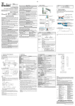
4. Precautions For Use
Q62AD-DGH Channel Isolated High Resolution AnalogDigital Converter Module (with Signal Conditioning Function)
Thank you for buying the Mitsubishi programmable logic controller MELSEC
Q Series.
User's Manual
(Hardware)
MODEL
MODEL
Code
Q-A/D-DGH-U-HW
13JT83
IB-0800224-A (0204) MEE
©2002 MITSUBISHI ELECTRIC CORPORATION
SAFETY PRECAUTIONS
Model name
Number of
Input
analog input
specification
Analog input
Supply
Connecting
voltage
section with
Maximum
2-wire
Supply power
transmitter specification supply
current
Short-circuit
protection
Check terminals
DANGER
Procedures which may lead to a dangerous condition and
cause death or serious injury if not carried out correctly.
CAUTION
Procedures which may lead to a dangerous condition and
cause superficial to medium injury, or physical damage
only, if not carried out correctly.
Depending on circumstances, procedures indicated by
CAUTION may also cause
to serious accidents.
In any case, it is important to follow the directions for usage.
Store this manual in a safe place so that you can take it out and read it whenever
necessary. Always forward it to the end user.
Available
Limit current: 25 to 35mA
Available
16-bit signed binary (-768 to 32767)
32-bit signed binary (-1538 to 65535)
±0.05%
*3
*3
Digital output value (32-bit): ±32digit Digital output value (16-bit): ±16digit
Reference
*2
Accuracy (Accuracy accuracy
relative to full-scale) Temperature
*4
coefficient
Conversion speed
±71.4ppm/°C (0.00714 %/°C)
Insulation
2
E PROM write count
Number of I/O occupied points
Connected terminal
Applicable wire size
Applicable solderless terminals
[INSTALLATION PRECAUTIONS]
CAUTION
• Use the PLC in an environment that meets the general specifications given in the User's
Manual of the CPU module being used.
Using this PLC in an environment outside the range of the general specifications may
cause electric shock, fire, malfunction, and damage to or deterioration of the product.
• When installing the module, securely insert the module fixing tabs into the mounting holes
of the base unit while pressing the installation lever located a t the bottom of the module
downward.
Incorrect installation may result in malfunction or breakdown, or cause the module to
loosen and drop. Securely fix the module with screws if it is subject to vibration during use.
• Tighten the screws within the range of specified torque.
If the screws are loose, it may cause the module to fallout, short circuits, or malfunction.
If the screws are tightened too much, it may cause damage to the screw and/or the module,
resulting in fallout, short circuits or malfunction.
• Switch all phases of the external power supply off when mounting or removing the module.
Otherwise, the module may be damaged.
• Do not directly touch the conductive area or electronic components of the module.
Otherwise, the module may malfunction or go down.
4
5
6
7
8
CH2
P
I/CHK+
CHK-
9
10
11
12
13
14
Tightening torque range
15
IN24VDC
36 to 48 N · cm
16
17
42 to 58 N · cm
(FG)
66 to 89 N · cm
18
4~20mA
90 (3.54)
22 (0.87)
27.4 (1.08)
unit (mm (in.))
Wiring precautions
(4) A solderless terminal with insulation sleeve cannot be used for the
terminal block. It is recommended to cover the cable-connection portion of
the solderless terminal with a marked tube or an insulation tube.
5.2
External wiring
Warranty
*3
2-wire
+
transmitter
(4 to 20mA) -
P
I/CHK+
V+
V
V-
Current
limiting circuit
Transmitter
power supply
24V
24G
Insulating
circuit
250
CHK-
Mitsubishi Electric shall not be liable for any loss caused by reasons for which Mitsubishi is not held
accountable, lost business opportunities or unrealized gain on the customer's side resulting from failure of
the product, or any other damage, secondary disaster, accident, damage to equipment other than the
product or disruption of other business operations arising out of special circumstances which may or may
not have been predicted at Mitsubishi.
For safe use of the product
*1 Shielded
!
*5
*2
DC24V
24V
!
24V
!
24G
Filter
FG
This product is manufactured as a general-purpose product intended for general industrial use only. It is
not designed nor manufactured for use in an equipment or system affecting human lives.
If you are considering to use this product in equipment or systems for nuclear power generation, power
generation, aerospace, medical or passenger transport applications, consult our sales representatives.
This product is manufactured under our strict quality control system. However, if the product is used in the
intended facility in such a way that a failure of the product may lead to serious accident or loss,
incorporate backup or fail-safe functions into the system design.
24G
*4
*1
*2
*3
*4
*5
This section explains the part names for the Q62AD-DGH.
1)
3)
Q62AD-DGH
RUN
ALM
ERR.
2)
CH1
P
I/CHK+
CHK-
1
2
3
4
5
6
4)
7
8
CH2
P
I/CHK+
CHK-
9
10
11
12
13
14
15
IN24VDC
5)
16
17
(FG)
18
4~20mA
Manual
Number
1)
RUN LED
Manual No. (Model code)
Conformation to the EMC Directive and Low Voltage Instruction
When complying with EMC Directives and Low-Voltage Directives by assembling a
Mitsubishi PLC compatible with EMC Directive and Low-Voltage Directives into the
user product, refer to Chapter 3 "EMC Directives and Low-Voltage Directives" in the
User's Manual (Hardware Section) for the CPU module being used. The CE logo is
printed on the rating plate on the main body of the PLC that conforms to the EMC
directive and low voltage instruction.
Q62AD-DGH
2
(3) Ground one point of the shield for shielded wires or shielded cables.
3. Part Names
CAUTION
SH-080277
(13JR51)
500VDC 10MΩ
more
Internal current consumption (5 VDC)
Weight
*1: User range setting is 2 to 24mA.
*2: Accuracy of offset/gain setting at ambient temperature
Q62AD-DGH needs to be powered on 30 minutes prior to operation for compliance to the specification
(accuracy).
*3: “digit” indicates a digital output value.
*4: Accuracy per temperature change of 1 °C
Example: Accuracy when temperature changes from 25 to 30 °C
0.05% (reference accuracy) + 0.00714 %/°C (temperature coefficient) × 5 °C (temperature change
difference) = 0.0857%
• Always ground the FG terminal for the PLC.
There is a risk of electric shock or malfunction.
• When turning on the power and operating the module after wiring is completed, always
attach the terminal cover included with the product.
There is a risk of electric shock if the terminal cover is not attached.
• Tighten the terminal screws within the range of specified torque.
If the terminal screws are loose, it may result in short circuits or malfunction.
If the terminal screws are tightened too much, it may cause damage to the screw and/or the
module, resulting in short circuits or malfunction.
• Be careful not to let foreign matters such as sawdust or wire chips get inside the module.
These may cause fires, failure or malfunction.
• The top surface of the module is covered with protective film to prevent foreign objects such
as cable offcuts from entering the module when wiring.
Do not remove this film until the wiring is complete. Before operating the system, be sure to
remove the film to provide adequate heat ventilation.
Related Manual
Isolation voltage
24VDC +20%, -15%
Ripple, spike within 500mVP-P
Inrush current : 5.5A, within 200µs
0.36A
0.22A
0.19kg
External supply power
[WIRING PRECAUTIONS]
The following manual is also related to this product. Order them if necessary.
Dielectric strength
Between I/O
Photocoupler
terminal and PLC
insulation
power supply
1780VAC rms
Between analog Transformer
/3 cycles
input channels
isolation
(elevation 2000m)
Between external
Transformer
supply power and
isolation
analog input
Maximum 100,000
16 points
18 points terminal block
2
0.3 to 0.75mm
R1.25 - 3 (A solderless terminals with sleeves cannot be used)
Item
• Do not bunch the control wires or communication cables with the main circuit or power
wires, or install them close to each other.
They should be installed 100 mm (3.94 inch) or more from each other.
Otherwise, noise may occur and result in malfunction.
Insulation
method
1
3
(1) Wire the external AC control circuit and the external input signal for Q62ADDGH and the external supply power with the separate cables to prevent the
influence of surge or induction from AC side.
(2) Do not mount the cables close to or bundle them with main circuit line, a
high-voltage cable or load cable from other than the PLC. This may
increase the effects of noise, surges and induction.
10ms/2 channels
Isolated part
CHK-
5. Wiring
5.1
P
I/CHK+
(6) To mount the module on the base, securely insert the module fastening
latch into the fastening hole on the base. Incorrect mounting may result in
a module malfunction, or may cause the module to fall off.
Maximum resolution Digital output Digital output
Analog input range
32-bit
16-bit value (32-bit) value (16-bit)
4 to 20mA
250.0nA 500.0nA
0 to 64000
0 to 32000
Users range setting 151.6nA 303.2nA
Model name
CAUTION
Screw location
Module mounting screw (M3 screw)
Terminal block terminal screw (M3 screw)
Terminal block mounting screw (M3.5 screw)
24mADC
I/O characteristics, Maximum resolution
[DESIGN PRECAUTIONS]
Manual Name
Channel Isolated High Resolution Analog-Digital Converter
Module Channel Isolated High Resolution Analog-Digital
Converter Module (with Signal Conditioning Function) User’s
Manual
2 points (2 channels)
26±2VDC
CH1
(5) Tighten the terminal screws for the module to the specified torque shown
below.
Insufficient tightening torque could result in shorts, failures or malfunction.
4 to 20 mADC *1(Input resistance 250 Ω)
ALM
ERR.
(4) The top surface of the module is covered with a protective film to prevent
foreign objects such as wire burrs from entering the module during wiring.
Do not remove this film until the wiring is complete. Before operating the
system, be sure to remove the film to provide adequate ventilation.
Q62AD-DGH
Item
RUN
(3) Be careful not to let foreign particles such as swarf or wire chips enter the
module. They may cause a fire, mechanical failure or malfunction.
The specifications for the Q62AD-DGH are shown in the following table. For
general specifications for the Q62AD-DGH, refer to the operation manual for
the CPU module being used.
Digital output
(Read these precautions before using.)
When using Mitsubishi equipment, thoroughly read this manual and the related
manuals introduced in the manual. Also pay careful attention to safety and handle the
module correctly.
These precautions apply only to this product. Refer to the user’s manual of the CPU
module to use for the PLC system safety precautions.
These
SAFETY PRECAUTIONS
classify the safety precautions into two
categories: "DANGER" and "CAUTION".
Q62AD-DGH
(2) Do not remove the PCB of the module from its case. This may cause the
module to fail.
2. Specifications
Prior to use, please read both this manual and detailed manual thoroughly
and familiarize yourself with the product.
6. External Dimensions
(1) Do not drop the module case or subject it to strong impact.
This manual explains the specifications and part names for the type Q62AD-DGH
Channel Isolated High Resolution Analog-Digital Converter Module (with Signal
Conditioning Function) (hereinafter Q62AD-DGH) to be used in combination with
the MELSEC-Q Series CPU module.
98 (3.86)
1. Overview
2)
3)
4)
5)
Name
Terminal number
Signal name *
1
P
2
I/CHK+
CH1
3
CHK4
Empty
5
Empty
6
Empty
7
Empty
8
Empty
9
P
10
I/CHK+
CH2
11
CHK12
Empty
13
Empty
14
Empty
15
Empty
16
24V
17
24G
18
FG
*P
: Power supply for 2-wire transmitter
I/CHK+ : 2-wire transmitter current input/check (+) terminal
CHK- : Check (-) terminal
Description
Displays the operating status of the Q62AD-DGH.
On
: Normal operation
Flickering : During offset/gain setting mode
Off
: 5V power supply interrupted, watch dog timer error or module
exchangeable status during online module replacement
ERR. LED
Displays the error status of the Q62AD-DGH.
On
: Error (A/D conversion continues.)
Flickering : Error (A/D conversion stops.)
Off
: Normal operation
ALM LED
Displays the alarm status of the Q62AD-DGH.
On
: An alarm (process alarm, rate alarm) is being generated.
Flickering : An input signal error is being generated.
Off
: Normal operation
Check terminals
Terminal used to check the analog input current value. (See Section 5.2)
External supply power terminal Terminal to connect 24VDC external supply power.
Use a 2-core twisted shielded wire for the power wire.
Shows input resistance.
To connect with the 2-wire transmitter, be sure to connect to P and I/CHK+.
Always use a ground. In addition, ground the FG of the power supply module.
The check terminals (I/CHK+, CHK-) are used to check the amount of input in mA
in relation to the 2-wire transmitter output. This can be checked since analog inputs
of 4 to 20mA are converted to analog outputs of 1 to 5V.
The relationship of this conversion can be expressed by the following formula:
Analog input (mA)
× 250 Ω
Analog output (V) =
1000
IMPORTANT
Q62AD-DGH needs to be powered on 30 minutes prior to operation for compliance to the specification (accuracy).
Therefore, power on 30 minutes prior to offset/gain setting or after online module replacement.
5.3
Switch setting for intelligent functional module
The settings for the intelligent function module are performed using the I/O
allocation settings for the GX Developer.
It can be easy to set by inputting in hexadecimal-4digits.
Setting
Input range setting
Switch 1
H
00H Fixed
CH2 CH1
Analog input range
4 to 20 mA
User range setting
Switch 2
Switch 3
Input range setting value
0H
FH
Empty
Empty
H
Switch 4
Country/Region Sales office/Tel
China
Ryoden International Shanghai Ltd.
3F Block5 Building Automation
Instrumentation Plaza 103 Cao Bao Rd.
Shanghai 200233 China
Tel : +86-21-6475-3228
Taiwan
Setsuyo Enterprise Co., Ltd.
6F., No.105 Wu-Kung 3rd.RD, Wu-Ku
Hsiang, Taipei Hsine, Taiwan
Tel : +886-2-2299-2499
Korea
HAN NEUNG TECHNO CO.,LTD.
1F Dong Seo Game Channel Bldg.,
660-11, Deungchon-dong Kangsec-ku,
Seoul, Korea
Tel : +82-2-3660-9552
Singapore
Mitsubishi Electric Asia Pte, Ltd.
307 ALEXANDRA ROAD #05-01/02,
MITSUBISHI ELECTRIC BUILDING
SINGAPORE 159943
Tel : +65-473-2480
Thailand
F. A. Tech Co.,Ltd.
898/28,29,30 S.V.City Building,Office
Tower 2,Floor 17-18 Rama 3 Road,
Bangkpongpang, Yannawa,
Bangkok 10120
Tel : +66-2-682-6522
Indonesia
P.T. Autoteknindo SUMBER MAKMUR
Jl. Muara Karang Selatan Block A Utara
No.1 Kav. No.11 Kawasan Industri/
Pergudangan Jakarta - Utara 14440
Tel : +62-21-663-0833
India
Messung Systems Put,Ltd.
Electronic Sadan NO:111 Unit No15,
M.I.D.C BHOSARI,PUNE-411026
Tel : +91-20-7128927
Australia
Mitsubishi Electric Australia Pty. Ltd.
348 Victoria Road, PostalBag, No 2,
Rydalmere, N.S.W 2116, Australia
Tel : +61-2-9684-7777
HEAD OFFICE : 1-8-12, OFFICE TOWER Z 14F HARUMI CHUO-KU 104-6212, JAPAN
NAGOYA WORKS : 1-14, YADA-MINAMI5, HIGASHI-KU, NAGOYA, JAPAN
000H Fixed
0H : Normal mode (A/D conversion processing)
1 to FH (numeric value other than 0H) : Offset/gain setting mode
Switch 5
Country/Region Sales office/Tel
U.S.A
Mitsubishi Electric Automation Inc.
500 Corporate Woods Parkway Vernon
Hills, IL 60061
Tel : +1-847-478-2100
Brazil
MELCO-TEC Rep. Com.e Assessoria
Tecnica Ltda.
Av. Rio Branco, 123-15 ,and S/1507,
Rio de Janeiro, RJ CEP 20040-005,
Brazil
Tel : +55-21-221-8343
Germany
Mitsubishi Electric Europe B.V. German
Branch
Gothaer Strasse 8 D-40880 Ratingen,
GERMANY
Tel : +49-2102-486-0
U.K
Mitsubishi Electric Europe B.V. UK
Branch
Travellers Lane, Hatfield, Herts., AL10
8XB,UK
Tel : +44-1707-276100
Italy
Mitsubishi Electric Europe B.V. Italian
Branch
Centro Dir. Colleoni, Pal. Perseo - Ingr.2
Via Paracelso 12, 20041 Agrate B.,
Milano, Italy
Tel:+39-039-60531
Spain
Mitsubishi Electric Europe B.V. Spanish
Branch Carretera de Rubi 76-80
08190 - Sant Cugat del Valles,
Barcelona, Spain
Tel:+34-935-653135
South Africa
Circuit Breaker Industries LTD.
Private Bag 2016, Isando 1600,
Johannesburg, South Africa
Tel : +27-11-928-2000
Hong Kong
Ryoden Automation Ltd.
10th Floor, Manulife Tower, 169 Electric
Road, North Point, HongKong
Tel : +852-2887-8870
0 : Fixed
When exported from Japan, this manual does not require application to the Ministry
of Economy, Trade and Industry for service transaction permission.
Specifications subject to change without notice.
Printed in Japan on recycled paper.