1
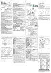
1. GENERAL DESCRIPTION [DESIGN PRECAUTIONS] DANGER High Speed Counter Module Type A1SD61 User’s Manual (Hardware) Thank you for buying the Mitsubishi general-purpose programmable z Failure of external output transistors could cause outputs to remain continually ON or continually OFF. Provide an external circuit to monitor output signals whose disruption could cause serious accidents. This manual describes specifications, handling and wiring of an A1SD61 high speed counter module (hereinafter referred to as the A1SD61). 1994 MITSUBISHI ELECTRIC CORPORATION zSAFETY PRECAUTIONSz (Read these precautions before using.) When using Mitsubishi equipment, thoroughly read this manual and the associated manuals introduced in the manual. Also pay careful attention to safety and handle the module properly. These precautions apply only to Mitsubishi equipment. Refer to the CPU module user’s manual for a description of the PC system safety precautions. These zSAFETY PRECAUTIONSz classify the safety precautions into two categories: "DANGER" and "CAUTION". DANGER CAUTION Procedures which may lead to a dangerous condition and cause death or serious injury if not carried out properly. Procedures which may lead to a dangerous condition and cause superficial to medium injury, or physical damage only, if not carried out properly. CAUTION may also Depending on circumstances, procedures indicated by be linked to serious results. In any case, it is important to follow the directions for usage. Store this manual in a safe place so that you can take it out and read it whenever necessary. Always forward it to the end user. 50K 10K 5V 12V 24V 2) 2. PERFORMANCE SPECIFICATIONS 5) CAUTION z Use the PC in the environment specified in the General Specifications section in this manual. Using it in an environment which does not meet the general specifications could cause electric shock, fire or malfunctions, and damage or deterioration of the module. z Do not bundle the control wire and the communication cable with the main circuit or power line or keep them close to one another. Keep the control wire and the communication cable at least 150 mm away from the main circuit or power line: otherwise, noise or malfunctions will occur. Item Counting speed selection pin Number of occupied I/O points Number of channels Phase Count input Signal levels signal ( A and B) Maximum counting speed Counting range [INSTALLATION PRECAUTIONS] CAUTION z Do not directly touch the conducting part of the module. Failure to observe this instruction will cause the module to malfunction or break down. z Install the module by engaging the module mounting projections on the lower part of the module in the mounting holes of the base unit. Incorrect installation could result in malfunctions, failure of detachment. Type Counter [WIRING PRECAUTIONS] CAUTION z The twisted shielded wire must be grounded to at least class 3 specifications at the encoder side (relay box). z Ground the AG terminal using third class grounding or higher exclusively for the PC. If you do not, the PC will malfunction. z Before connecting wires to the PC, check the rated voltage and the terminal arrangement. Connecting power of a different voltage or wiring incorrectly will result in fire or failure. z Do not apply the voltage higher than the value set with a jumper. Failure to observe this instruction will result in failure. z Tighten the terminal screws to the specified torque. Loose terminal screws will cause a short, fire or malfunctions. Tightening the terminal screws too far may cause damage to the screws resulting in short circuits or malfunctions. z Take all possible measures to prevent chips or wire scraps from entering the module. Entry of foreign material will cause fire, failure of malfunctions. Limit switch output External input External output z Do not touch the terminals while they are live. This will cause malfunctions. z Switch the power off before cleaning the module or retightening the terminal screws. If the power is left on, the module will break down or malfunction. CAUTION z Do not disassemble or tamper with the module. This will cause failure, malfunctions, injuries or fire. z Switch the power off before installing or removing the module. If the power is left on, the module will break down or malfunction. [DISPOSAL PRECAUTIONS] CAUTION z Dispose of the module as industrial waste. Detailed Manual Manual Name High speed counter module type A1SD61 User's Manual Manual No. (Type code) IB-66337 (13J674) 6 7 F.START 8 9 5V 12V 24V 1 3 50k pps 5 4) Isolation method 9) 6 7 8 + - NO. (1) (2) (3) (4) Dielectric Insulation withstand resistance voltage Between pulse input terminal and PLC power supply Between preset input terminal and PLC power supply Photocou 500V AC/1 Between function pler isolation minute. start input terminal and PLC power supply Between coincidence output terminal and PLC power supply or 5M more by 500V DC insulation resistance tester. 0.75 to 1.5 mm2 Applicable wire size Applicable solderless R1.25-3, 1.25-YSA, RAV1.25-3, V1.25-YS3A terminals Internal current 0.35 A consumption (5 VDC) Weight kg (lb) 0.27 (0.59) *1: The counting speed is influenced by the pulse leading edge/fall time. The following counting speeds are possible. If a pulse is counted with a leading edge/fall time that is too long, a counter error may be caused. Counting Speed 50k 10k Setting Pin Leading 1-phase 2-phase 1-phase 2-phase Edge/Fall input input input input Time t=5 s t t 50k pps 50k pps 10k pps 7k pps or less t=50 s 5k pps 5k pps 1k pps 700 pps or less — — 500 pps 250 pps t=500 s For the general specifications, refer to the User’s Manual for the PC CPU used. 10 11 12 13 14 15 16 17 18 19 COM 20 DC12/24V 0.1A A1SD61 10k pps About This Manual The following manuals are also related to this product. In necessary, order them by quoting the details in the tables below. 5 PRESET 4 50k pps 7k pps *1 2-phase input 32-bit binary -2147483648 to 2147483647 Equipped with UP/DOWN preset counter and ring counter functions Unit: s Unit: Specific isolated area Isolation specifications 3 4 2 1 1-phase and 2-phase inputs 5 VDC 12 VDC 2 to 5 mA 24 VDC 1-phase input 1 2 B L Minimum s count pulse 20 100 142 width Set input rise and fall times 71 71 50 50 10 10 or to 5 less. Duty (1-phase and 2-phase (1-phase (2-phase ratio: 50% input) input) input) Comparison 32-bit binary range A contact operation: Dog ON address < Count value < Dog OFF address Comparison B contact operation: Dog OFF address < Count value < result Dog ON address Preset 12/24 VDC 3/6 mA Function start 5 VDC 5 mA Coincidence Transistor (open collector) output output 12/24 VDC 0.1 A/point 0.8 A/common [STARTING AND MAINTENANCE PRECAUTIONS] DANGER 10K side 32 2 3 4 5 6 7 8 A 7) 8) 3) 1 B 5V 12V 24V Specifications 50K side OUT RUN A B PRESET FUNCTION 6) thoroughly and familiarize yourself with the product. MODEL A1SD61 (H/W)-U-E MODEL 13JE47 CODE IB(NA)-66486-B(0209)MDOC A1SD61 A 1) logic controller MELSEC-A Series Prior to use, please read both this manual and detailed manual 3. NOMENCLATURE (5) (6) (7) (8) (9) Name Description Counting speed selection Counts pulses at a maximum speed of 50k pps in pin 1-phase or 2-phase input. Counts pulses at 10k pps in 1-phase input, at 7k 50K pps in 2-phase input. (The factory-setting is 50k.) 10K (Set with the jumper) Select a pulse voltage that is input to Phase A or B. Input pulse voltage (The factory-setting is 24 V.) selection pin The module operation cannot be guaranteed when A B the pulse voltage higher than the set value is 5V 5V 12V 12V applied. 24V 24V (Set with the jumper) Select a voltage input to the PRESET/F.START External input voltage terminals. selection pin (The factory-setting is 24 V.) 5V The module operation cannot be guaranteed when 12V the voltage higher than the set value is applied. 24V (Set with the jumper). Used for protecting outputs 1 to 8 from overcurrent. Fuse (Circuit board soldering type) Lit when the module operates normally. RUN Flashes when a data write error has occurred. OFF when a watchdog timer error has occurred. Lit when voltage is applied to phase A pulse input A terminal. Lit when voltage is applied to phase B pulse input B terminal. LED Lit and latched when voltage is applied to the indicators PRESET terminal. PRESET OFF when external preset detection reset signal (Y16) is turned ON. ON when voltage is applied to the F.START FUNCTION terminal. ON when a corresponding limit switch is turned ON OUTs 1 to 8 by he limit switch output function. OFF when the limit switch is turned OFF. Pulse input terminals ( B is used as decrement A/ B count command.) The terminal in which voltage is applied when a PRESET preset is executed from an external device. The terminal in which voltage is applied when a F. START counter function selection is executed. An external output terminal used for limit switch OUTs 1 to 8 output. 5.2 Wiring example for the connection with the open collector output pulse generator 4. LOADING AND INSTALLATION 4.1 Cautions on Handling (1) The case of the A1SD61 is made of resin: do not drop it or subject it to strong impact. (2) Do not remove the printed circuit board from the case. This could cause failure. (3) Make sure that no wire offcuts or other debris enters the top of the module during wiring. If anything does enter the module, remove it. (4) Tighten the module mounting and terminal screws as specified below: (2) When a controller (source load type) is supplied with 5 V: A1SD61 External input voltage setting pin* (1) Connection of a 24 VDC pulse generator 680Ω 1/4W A1SD61 2.2kΩ Pulse generator E OUT P R E S E T or F.S TA R T Twisted pair wire 4.7kΩ1/4W φA +24V 470Ω1/4W Tightening Torque Range N·cm Screw [kg·cm] (lb·inches) Module mounting screw (M4 screw) 78 to 118 [8 to 12] (6.93 to 10.4) Terminal block terminal screw (M3.5 screw) 59 to 88 [6 to 9] (5.19 to 7.8) Terminal block mounting screw (M4 screw) 78 to 118 [8 to 12] φB OUT Twisted pair wire 4.7kΩ1/4W This diagram assumes that the internal circuit is set to PRESET. E Shield Pulse input voltage setting pin* 2.2kΩ 1/4W +24 φB REMARK * : Set the external input voltage setting pin to the E +24V External 24 VDC poser 0V supply 0V 5.4 Wiring examples at external output terminals (OUT1 to OUT8) To use an OUT terminal, the internal photocoupler should be activated. For this example, 10.2 to 30 VDC external power is necessary. Connection methods are as follows: A1SD61 The method for wiring a pulse generator to the A1SD61 is described here. 5.1 Wiring precautions Wire a pulse generator to the A1SD61 while paying attention to the followings; (1) For a high-speed pulse input, take the following counter measures against noise; (a) Be sure to use shielded twisted pair cables. Also, make sure they are grounded to the earth. (b) Do not run a twisted pair cable in parallel with power cables or other I/O lines which may generate noise. Run cables at least 150 mm (5.91in.) away from the above-mentioned lines and over the shortest distance possible. (2) For 1-phase input, connect count input signal to phase A only. (3) If the A1SD61 picks up pulse noise, it will count incorrectly. (4) The specific measures against noise are shown below; AISD61 A1SD61 OUT8 OUT φA R Fuse +24V Encorder 0V E + External power supply A1SD61 INCORRECT + - COM 10.2 to 30V OUT Since the same twisted pair wire is used for both the encoder +24V Encorder signal and the power supply, a reduction in the cancelling 0V effect and electromagnetic E induction may occur. φA φA A1SD61 *1 470Ω1/4W Pulse input voltage setting pin* 2.2kΩ 1/4W 4.7kΩ1/4W Pulse generator 6. OUTSIDE DIMENSIONS φA φA OUT Twisted pair wire GND A1SD61 RUN 470Ω1/4W Shield 2.2kΩ Joint box 1/4W V WE 4.7kΩ1/4W *2 φB φB Pulse input voltage setting pin* Twisted pair wire E φA φB PRESET FUNCTION OUT OUT 1 2 3 4 5 6 7 8 GND Carrier Shield Encoder *1: Metal piping Never run solenoid or inductive wiring through the same conduit. If sufficient distance cannot be provided between the high current line and input siring, use shielded wire for the high current line. *2: Distance between the encoder and the joint box should be as short as possible. If the distance from the A1SD61 to the encoder is too long, an excessive voltage drop occurs. Therefore, measure the voltage during operation and make sure that the voltage are within the rated voltage of the encoder. If the voltage drop is large, increase the size of wiring or use an encoder of 24 VDC with les current consumption. E +5VDC External +5 VDC poser 0V supply 0V REMARK * : Set the pluse input voltage setting pin to the position. 5.3 Wiring Example for the Connection of a Controller to External Input Terminals (PRESET and F.START) (1) When a controller (sink load type) is supplied with 12 V: y Ground twisted shielded wire on the encoder side (joint box) A1SD61 External input voltage setting pin* (This is a connection example for 24 V send load) Power supply for encorder L 12/24V REMARK * : Set the pulse input voltage setting pin to the position. (2) Connection of a voltage output pulse generator (5 VDC) Separate more than 150 mm from equipment such as inverters. (Also take care of wiring inside the panel) AC motor L CORRECT φA + External power supply Inverter Terminal block Terminal block OUT1 POINT The encoder signal and supply lines should be wired as shown below: 130 (5.1) PC 680Ω 1/4W +24V 0V To encorder φA φB To φA To φB To A1SD61 position. V Shield 5. WIRING - 4.7kΩ 1/4W φA 1/4W 5 VDC Twisted shield wire Pulse input voltage setting pin* 470Ω1/4W Controller P R E S E T or F.S TA R T Controller P R E S E T or F.S TA R T +12 VDC Twisted shield wire 4.7kΩ 1/4W E P R E S E T or F.S TA R T 24V E This diagram assumes that the internal circuit is set to PRESET. E Connect the encoder shield wire to the twisted pair shield wire of the encoder that is not grounded in the encorder Grounded it inside the joint box as indicated by dotted line 0 1 2 3 4 5 6 7 8 9 A B C D E F - 6.5 (0.26) 93.6 (3.69) 34.5 (1.36) Unit: mm (Inch) Warranty Mitsubishi will not be held liable for damage caused by factors found not to be the cause of Mitsubishi; machine damage or lost profits caused by faults in the Mitsubishi products; damage, secondary damage, accident compensation caused by special factors unpredictable by Mitsubishi; damages to products other than Mitsubishi products; and to other duties. For safe use y This product has been manufactured as a general-purpose part for general industries, and has not been designed or manufactured to be incorporated in a device or system used in purposes related to human life. y Before using the product for special purposes such as nuclear power, electric power, aerospace, medicine or passenger movement vehicles, consult with Mitsubishi. y This product has been manufactured under strict quality control. However, when installing the product where major accidents or losses could occur if the product fails, install appropriate backup or failsafe functions in the system. Country/Region Sales office/Tel U.S.A Mitsubishi Electric Automation Inc. 500 Corporate Woods Parkway Vernon Hills, IL 60061 Tel : +1-847-478-2100 Brazil MELCO-TEC Rep. Com.e Assessoria Tecnica Ltda. Av. Rio Branco, 123-15 ,and S/1507, Rio de Janeiro, RJ CEP 20040-005, Brazil Tel : +55-21-221-8343 Germany Mitsubishi Electric Europe B.V. German Branch Gothaer Strasse 8 D-40880 Ratingen, GERMANY Tel : +49-2102-486-0 U.K Mitsubishi Electric Europe B.V. UK Branch Travellers Lane, Hatfield, Herts., AL10 8XB,UK Tel : +44-1707-276100 Italy Mitsubishi Electric Europe B.V. Italian Branch Centro Dir. Colleoni, Pal. Perseo - Ingr.2 Via Paracelso 12, 20041 Agrate B., Milano, Italy Tel:+39-039-60531 Spain Mitsubishi Electric Europe B.V. Spanish Branch Carretera de Rubi 76-80 08190 - Sant Cugat del Valles, Barcelona, Spain Tel:+34-935-653135 South Africa Circuit Breaker Industries LTD. Private Bag 2016, Isando 1600, Johannesburg, South Africa Tel : +27-11-928-2000 Hong Kong Ryoden Automation Ltd. 10th Floor, Manulife Tower, 169 Electric Road, North Point, HongKong Tel : +852-2887-8870 Country/Region Sales office/Tel China Taiwan Korea Singapore Thailand Indonesia India Australia Ryoden International Shanghai Ltd. 3F Block5 Building Automation Instrumentation Plaza 103 Cao Bao Rd. Shanghai 200233 China Tel : +86-21-6475-3228 Setsuyo Enterprise Co., Ltd. 6F., No.105 Wu-Kung 3rd.RD, Wu-Ku Hsiang, Taipei Hsine, Taiwan Tel : +886-2-2299-2499 HAN NEUNG TECHNO CO.,LTD. 1F Dong Seo Game Channel Bldg., 660-11, Deungchon-dong Kangsec-ku, Seoul, Korea Tel : +82-2-3660-9552 Mitsubishi Electric Asia Pte, Ltd. 307 ALEXANDRA ROAD #05-01/02, MITSUBISHI ELECTRIC BUILDING SINGAPORE 159943 Tel : +65-473-2480 F. A. Tech Co.,Ltd. 898/28,29,30 S.V.City Building,Office Tower 2,Floor 17-18 Rama 3 Road, Bangkpongpang, Yannawa, Bangkok 10120 Tel : +66-2-682-6522 P.T. Autoteknindo SUMBER MAKMUR Jl. Muara Karang Selatan Block A Utara No.1 Kav. No.11 Kawasan Industri/ Pergudangan Jakarta - Utara 14440 Tel : +62-21-663-0833 Messung Systems Put,Ltd. Electronic Sadan NO:111 Unit No15, M.I.D.C BHOSARI,PUNE-411026 Tel : +91-20-7128927 Mitsubishi Electric Australia Pty. Ltd. 348 Victoria Road, PostalBag, No 2, Rydalmere, N.S.W 2116, Australia Tel : +61-2-9684-7777 HEAD OFFICE : 1-8-12, OFFICE TOWER Z 14F HARUMI CHUO-KU 104-6212, JAPAN NAGOYA WORKS : 1-14, YADA-MINAMI5, HIGASHI-KU, NAGOYA, JAPAN When exported from Japan, this manual does not require application to the Ministry of Economy, Trade and Industry for service transaction permission. Specifications subject to change without notice. Printed in Japan on recycled paper.