1
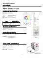
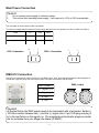
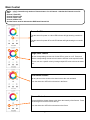
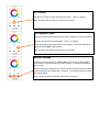
USER MANUAL
Table of Contents
Safety Information………………………………………………………………3
Specifications…………………………………………………………………...4
Main Power Connection………………………………………………………..5
DMX-512 Connection…………………………………………………………..5
Main Control Menu......................................................................................6
Installing the Fixture……………………..……………………………………...8
Cleaning & Maintenance.............................................................................8
Parts List.....................................................................................................8
Check that the unit has not been damaged during transport
Protection Against Fire
1.
3.
4.
5.
6.
Maintain a minimum of 1 foot distance from any type of flame.
Replace fuse only with the specified type and rating.
Do Not install the unit to close to a heat source.
Make sure cable are properly secured away.
Maximum surface operating temperature 104º.
Protection Against Fire
1.
2.
3.
4.
Disconnect power before servicing.
For connection to main power supply proceed to page 5.
This unit must be earthed. (electronically grounded)
Do not expose unit to rain or moisture.
Protection Against Mechanical Hazards
1. Use quality gang box when installing unit.
2. Use quality bolts when positioning unit
3. Do not open unit while it is on, risk of electrical shock.
3
Technical Information
Part Numbers
Fixture
MC-2030
MEA-APV-12-12
Xwitch
Mean Well 12V power Supply (included)
Mechanical Specifications
DMX Connectors:
.42”
2.95”
3 screw binding strip
Power Connections: 2 screw binding strip
Thermal:
Maximum ambient temperature 104°
Maximum surface temperature 140°
Display:
LED power indicator
Mounting System:
Single gang electrical wall mounting
4.72”
Fixture
2.05”
Packaged for Shipping
Size: 2.95”L x 1.19”W x 4.72”H
Size: 9” X 6.5” X 2.75”
Weight: 1 lbs
Weight: 3 lbs
1.19”
Electrical Specifications
Power Requirements:12-24VDC 0.2 Amps
Touch Sensor:
Single touch glass sensor
Control & Programming
Protocol:
DMX 512
DMX Channels:
4 DMX Channels
Operating Mode:
3 Programmable static scenes
10 Built in Preprogram chases with Speed control
3 Color Temperature presets
Dimmer intensity button
2.05”
Power Supply Specifications
Model:
Mean Well APV-12-12
Input Power
100-240VAC 50/60Hz
Output Power:
12 VDC 1 Amps
Power Connection:
Bare Cable
Mounting System:
2 hole screw mounting
4
Main Power Connection
Caution!
1.
2.
Do not connect power supply to a dimmer system.
This unit has Auto switching power supply. It will respond to 110V or 220V automatically
The occupation of the connection-cable is as follows:
This fixture is equipped with an electronic power supply that will let the unit operate from 100V to 240V from 50Hz to
Cable
Pin
110V
220V
Brown
Live
L
L
Light Blue
Neutral
N
L
110V—Connection
N
L
L
L
220V—Connection
DMX-512 Connection
The fixture is equipped with 3 Screw binding post for DMX output. Only use a shielded twisted pair cable designed for
RS-485 and 3 pin XLR plugs and connectors in order to connect the controller with the fixture.
DMX—output
GND =Shield= 1
D- =Signal (-)= 2
D+ =Signal (+)= 3
1
2
4. N/A
1
5
2
4
5. N/A
3
Caution!
3
At the last fixture the DMX signal needs to be terminated with a terminator. Solder a
120 Ohm resistor between the (-) and the (+) signal into a 3 pin XLR plug and plug it
in to the last fixture on the signal run. Pre-manufactured terminator plugs are available for purchase from your Mega-Lite dealer (P-DMXT).
5
Main Control
Note:
Controller only works on fixtures that are 3 or 4 Channel. And that the Channel are as follows.
Channel 1 Red LED
Channel 2 Green LED
Channel 3 Blue LED
Channel 4 White LED
And the fixture must be addressed to DMX start Channel 001
Power On/Off
Tap the screen for power on a blue LED indicator will light showing controller is
on.
Tap the screen for power Off a red LED indicator will light showing the controller
is off.
Single color Control
Tap the corresponding circular color for the LED to come on or off. Press and
hold the corresponding circular color to have the LED dim to the required intensity.
You can mix a to a specific color by having multiple LED color active at the same
time.
Color Wheel Control
Tap any where on the circular color wheel to have the color activated.
Note: the white color LED will not be active in the fixture
Dimmer Control
Press and hold the dimmer button to dim down the intensity of the fixtures. Press
and hold again to have the fixtures dim Up.
Note: the white color LED will not be active on the fixture.
7
CTO Control
Tap the CTO button to select the White mixed color. There is 3 options
Note: the white color LED will not be active on the fixture.
Pre Programs Control
Tap once to start the preprogram function, tap once again to pause the program.
Tap twice to select the next preprogram. There is 10 options.
Press and Hold to adjust the speed up of the program. Press and hold again to
adjust the speed down of the program.
Note: the white color LED will not be active on the fixture.
Record Functions
All functions can be recorder to a Record Button (S1,S2, S3) including Single
Color Control, Color Wheel Control, Dimmer Control, CTO Control and Pre Program Control.
Select a function you would like to control Press and Hold any of the the S Button
for 2 seconds and the program will be recorded. To recall the program recorded
just Tap the button.
Note: White LED will be recorded to the Playback if selected
Installing the fixture
Caution!
1. The installations must be carried out by an authorized dealer or trained professional.
2. Unit may cause severe electrical injures if you have doubts concerning the safety
do not install.
When installing a unit it is very important that you follow common safety procedures. Installing requires extensive experience including but not limited to calculating voltage loads, material being used and periodic safety inspections. If you
lack these qualifications, do not attempt the installation yourself, instead use a professional electrician.
When installing the controller please make sure all safety rules are followed and it is installed in a appropriate housing.
Installation should be checked at least one time a year by a skilled person.
Cleaning and maintenance
Cleaning: Clean the front glass of the fixture with soap and warm water, never clean with strong soluble detergents.
Installation Maintenance: The operator has to make sure that the unit is operating safely and has the installations and electronics checked by an expert every 2 years.
The following points have to be considered during the inspection:
1) All screws used for installing the device or part of the device have to be tightly connected and must not be corroded.
2) There must not be any deformations on the housing, fixation and installation spot.
3) The electronic power supply cables must not show any damages, material fatigue (e.g. porous cables) or sediments.
Further instructions depending on the installation spot and usage have to be adhered by a skilled installer and any
Note: There is no serviceable parts inside the device. Maintenance and service operations are to be carried out
by authorized dealers.
Should you have further questions , please contact your dealer.
Parts List
MEA-APV-12-12
Power Supply
8
Warranty Information
Warranty Conditions
-Unless otherwise stated in writing, your product is covered by a one year parts and labor limited warranty.
-LEDs are not guaranteed to match in color temperature or output.
-It is the owner’s responsibility to furnish receipts or invoices for verification of purchase, date, and reseller or distributor.
If purchase date cannot be provided, date of manufacture will be used to determine warranty period.
-Goods returned under warranty must follow the proper authorization procedure and must be accompanied by a copy of
the original invoice.
-Goods repaired under warranty will be returned to the owner with the freight prepaid by MSI via the most economical
means of shipment.
-Repair or replacement as provided for under this warranty is the exclusive remedy of the consumer. MEGA SYSTEMS
INC. makes no warranties, express or implied, with respect to any product, and Mega Systems specifically disclaims any
warranty of merchantability or fitness for a particular purpose. Mega Systems shall not be liable for any indirect, incidental or consequential damage, including lost profit, sustained or incurred in connection with any product or caused by
product defect or the partial or total failure of any product regardless of the form of action, weather in contract, tort
(including negligence), strict liability or otherwise, and weather or not such damage was foreseen or unforeseen.
- Warranty is void if the product is misused, damaged, modified in any way, or for unauthorized repairs or parts. This
warranty gives you specific legal rights, and you may also have other rights which vary from state to state.
Mega-Lite
5718 Kenwick St
San Antonio, TX 78238
Ph 210-684-2600 Fax 210-855-6279
www.mega-lite.com / [email protected]