1
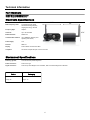
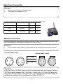
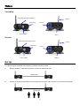
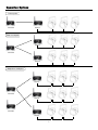
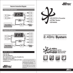
USER MANUAL
Safety Information
Specifications
Main Power Connection
DMX-512 Connection
Fixture Level
Set Up
Operation Options
Connection
Rigging the Fixture
Cleaning & Maintenance
Parts List
Table of Contents
3
4
5
5
6
6
7
8
9
9
9
Check that the unit has not been damaged during transport
Protection Against Fire
1.
3.
4.
5.
6.
Maintain a minimum of 1 foot distance from any type of flame.
Replace fuse only with the specified type and rating.
Do Not install the unit to close to a heat source.
Make sure cable are properly secured
Maximum surface operating temperature 120º.
Protection Against Fire
1.
2.
3.
4.
Disconnect power before servicing.
For connection to main power supply proceed to page 5.
This unit must be earthed. (electronically grounded)
Do not expose unit to rain or moisture.
Protection Against Mechanical Hazards
1. Use safety chain when hanging unit.
2. Use quality clamps or bolts when positioning unit
3. Do not open unit while it is on, risk of electrical shock.
3
Technical Information
Part Numbers
MC2040– Mega Air PRO DMX Transmitter
MC2041– Mega Air PRO DMX Receiver
Electronic Specifications
5.75”
Radio Frequency Used:
2.40-252G Automatic Select
126 Channels using frequency
Hopping technology—AFHSS
Frequency Agile:
Adaptive
Universes:
Up to 16 selectable
Broadcast Power:
20dBm max
Communication distance:
Up to 200Meters (Outdoor prime
operating environment)
Power Supply:
110v
Protocol:
DMX 512
Display:
Power indicator & Connection status
Compliant:
This device complies with part 15 of the FCC rules
4.70”
Mechanical Specifications
Fastening System:
Truss Mount Clamp & Mounting Holes
Power Connection:
Power Conn Type
Signal Connection:
XLR 3 & 5 pin In for Mega Air Pro Transmitter, XLR 3 & 5 Out for Mega Air Pro Receiver
Fixture
Packaging
Size: 5.75” x 5.5” x 4.70”
Size: 8” x 6.5” x 4”
Weight: 2lb
Weight: 3lb
5.5”
4
Main Power Connection
Caution!
1.
2.
Do not connect fixture to a dimmer system.
This fixture only operates on 110V
This fixture is equipped with a power supply that will let the unit operate from 100V to 110V
Cable (USA)
Cable (EU)
Pin
110V
Black
Brown
Live
L
White
Light Blue
Neutral
N
Green
Yellow/Green
Ground
Ground
DMX-512 Connection
The fixture is equipped with 3 and 5 pin XLR Sockets for DMX input or output. The sockets are wired in parallel. Only
use a shielded twisted pair cable designed for RS-485 and 3 or 5 pin XLR plugs.
Caution!
1.
Do not connect 2 input cable or 2 output cables at the same time from the input or output.
Transmitter DMX—input
Receiver DMX—output
1. Shield
2. Signal (-)
1
2
5
1
4
2
3
3. Signal (+)
3
1
2
2
4
3
Caution!
1
5
3
At the last fixture the DMX signal needs to be terminated with a terminator. Solder a
120 Ohm resistor between the (-) and the (+) signal into a 3 or 5 pin XLR plug and
plug it in to the last fixture on the signal run. Pre-manufactured terminator plugs are
available for purchase from your Mega-Lite dealer (P-DMX-T).
5
Fixture
Transmitter
Power ,DMX and Sending Indicators
Power Switch
Antenna
Power In
Function Button
DMX In
Receiver
Power ,DMX and Sending Indicators
Power Switch
Antenna
Power In
DMX Out
Function Button
Set Up
For optimum signal transmission the following conditions should be fulfilled.
A.
Distance between Transmitter and Receiver should not exceed 650 feet
650 feet max
B.
Position on the transmitter should be in clear sight of the receiver with a minimum of 3 feet above any person.
3 feet min
6
Operation Options
Point to point
Transmitter
Receiver
Point to multipoint
Receiver
Transmitter
Receiver
Multipoint to multipoint
Receiver
Transmitter
Receiver
Transmitter
Receiver
7
Connection
Point to Point Connection
1.1
1.2
1.3
1.4
1.5
Connect the Transmitter to power, the DMX indicator should be flashing green.
Connect DMX signal into the Transmitter, the DMX indicator should be solid green.
Connect the Receiver to power, the DMX indicator should be off ( if the receiver DMX light is not off you need to unlink your receiver)
Press and quickly release the Function button on the Transmitter. The transmitter will scan for all unlinked receiver for a period of 10 seconds– the
DMX indicator on both Transmitter and Receivers will flash rapidly.
If the connection is successful the DMX indicator on the Transmitter and Receiver will be green on. If the connection indicator is not on Green, check
the Receiver is in range and repeat the procedure.
that
Point to Multi Point Connection
1.1
1.2
1.3
1.4
1.5
Connect the Transmitter to power, the DMX indicator should be flashing green.
Connect DMX signal into the Transmitter, the DMX indicator should be solid green.
Connect the Receivers to power, the DMX indicator should be off ( if the receiver connection light is not off you need to unlink your receiver)
Press and quickly release the Function button on the Transmitter. The transmitter will scan for all unlinked receivers for a period of 10 seconds– the
connection indicator on both Transmitter and Receivers will flash rapidly.
If the connection is successful the DMX indicator on the Transmitter and Receivers will be solid green on. If the connection indicator is not on Green, check
that the Receiver is in range and repeat the procedure.
Multi Point to Multi Point Connection
1.1
1.2
1.3
1.4
1.5
1.6
1.7
1.8
1.9
1.10
1.11
Connect the First Transmitter to power, the DMX indicator should be flashing green.
Connect DMX signal into the First Transmitter, the DMX indicator should be solid green.
Connect the Receiver (s) to power, the DMX indicator should be off ( if the receiver connection light is not off you need to unlink your receiver)
Press and quickly release the Function button on the First Transmitter. The transmitter will scan for all unlinked receivers for a period of 10 seconds– the
DMX indicator on both Transmitter and Receivers will flash rapidly.
If the connection is successful the DMX indicator on the Transmitter and Receiver will be green on. If the connection indicator is not on Green, check
the Receiver is in range and repeat the procedure.
that
Connect the Second Transmitter to power, the DMX indicator should be flashing green.
Connect DMX signal into the Second Transmitter, the DMX indicator should be solid green.
Connect the Receiver (s) to power, the DMX indicator should be off ( if the receiver connection light is not off you need to unlink your receiver)
Press and quickly release the Function button on the Second Transmitter. The transmitter will scan for all unlinked receivers for a period of 10 seconds the
connection indicator on both Transmitter and Receivers will flash rapidly.
If the connection is successful the DMX indicator on the Transmitter and Receiver will be solid green on. If the connection indicator is not on Green, check
that the Receiver is in range and repeat the procedure.
You can repeat the process up to 16 Transmitters.
To unlink a Receiver
1.1
Press and hold the Function button on the Receiver for about 5 second until the DMX indicator flashes once and then goes off. Now the Receiver is unlinked
To unlink all Receiver
1.1
Press and hold the Function button on the Transmitter for about 5 second until the DMX indicator flashes once and then goes off. Now the Receivers are
unlinked
8
Rigging the fixture
Caution!
1. The installations must be carried out by an authorized dealer or trained professional.
2. Unit may cause severe injures if you have doubts concerning the safety do not install.
3. Unit is to be 24inches away from flammable materials (decoration material)
4. Use high quality installation equipment to hang unit.
When rigging a unit it is very important that you follow common safety procedures. Rigging requires extensive experience including but not limited to calculating working loads, material being used and periodic safety inspections. If you
lack these qualifications, do not attempt the installation yourself, instead use a professional structural rigger.
When rigging the unit always be secured with a secondary safety attachment. The installation location of the fixture has
got to be built in the way that it can hold 10 times the weight for 1 hour with out any harming. Installation should be
checked at least one time a year by a skilled person.
Cleaning and maintenance
Installation Maintenance: The operator has to make sure that the unit is operating safely and has the installations and electronics checked by an expert every year.
The following points have to be considered during the inspection:
1) All screws used for installing the device or part of the device have to be tightly connected and must not be corroded.
2) There must not be any deformations on the housing, fixation and installation spots (ceiling, suspension, trussing).
3) The electronic power supply cables must not show any damages, material fatigue (e.g. porous cables) or sediments.
Further instructions depending on the installation spot and usage have to be adhered by a skilled installer and any
safety problems have to be removed.
Note: There is no serviceable parts inside the device. Maintenance and service operations are to be carried out
by authorized dealers.
Replacing the power Supply: If the power supply of this device becomes damaged, it has to be replaced by authorized dealers or trained professional only.
Should you have further questions , please contact your dealer.
Parts List
9505-ANT
Replacement Antenna
MC2040-MPCB
Main PCB card Transmitter
MC2041-MPCB
Main PCB card Receiver
9
Warranty Information
Warranty Conditions
-Unless otherwise stated in writing, your product is covered by a one year parts and labor limited warranty.
-It is the owner’s responsibility to furnish receipts or invoices for verification of purchase, date, and reseller or distributor.
If purchase date cannot be provided, date of manufacture will be used to determine warranty period.
-Goods returned under warranty must follow the proper authorization procedure and must be accompanied by a copy of
the original invoice and Return Authorization Number given by MSI.
-Goods repaired under warranty will be returned to the owner with the freight prepaid by MSI via the most economical
means of shipment.
-Repair or replacement as provided for under this warranty is the exclusive remedy of the consumer. MEGA SYSTEMS
INC. makes no warranties, express or implied, with respect to any product, and Mega Systems specifically disclaims any
warranty of merchantability or fitness for a particular purpose. Mega Systems shall not be liable for any indirect, incidental or consequential damage, including lost profit, sustained or incurred in connection with any product or caused by
product defect or the partial or total failure of any product regardless of the form of action, weather in contract, tort
(including negligence), strict liability or otherwise, and weather or not such damage was foreseen or unforeseen.
- Warranty is void if the product is misused, damaged, modified in any way, or for unauthorized repairs or parts. This
warranty gives you specific legal rights, and you may also have other rights which vary from state to state.
Mega-Lite
5718 Kenwick St
San Antonio, TX 78238
Ph 210-684-2600 Fax 210-855-6279
www.mega-lite.com / [email protected]