1
IL MOD BK DI8 DO4-PAC
I2
C
4-PA
DO
DI8
BK 696
OD 78
IL M -No.: 28
CII
er
Ord
/AS
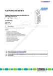
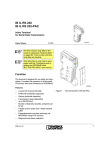
Inline bus coupler for Modbus with eight digital
inputs and four digital outputs
US
DB
MO
U
RT
S
ES 0
DR
AD
0 2
4
14
12
10
PWR
2
4
6
TR
UL
CO
US D
W
UM
D
E
2
1
4
3
2
1
4
3
7
5
8
6
98
x1
6
8
x1
I1
O1
0
MODBUS
AUTOMATION
Data sheet
7258_en_03
1
X1
© PHOENIX CONTACT - 09/2009
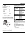
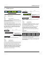
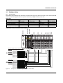
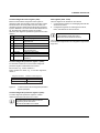
Description
The bus coupler is the link between the Modbus RTU/ASCII
system and the Inline installation system.
Up to 61 Inline terminals can be connected in any position to
an existing Modbus RTU/ASCII system using the bus
coupler. The bus coupler and the Inline terminals form one
station with a maximum of 63 local bus devices. Here, the
inputs and outputs of the bus coupler together form the first
and second local bus devices.
Up to eight PCP devices can be operated on the bus
coupler.
Features
–
–
–
–
–
–
–
–
–
–
–
–
Modbus RTU/ASCII
Modbus connection via 9-pos. D-SUB female
connector
Interface physics RS-485 for Modbus
Electrical isolation of Modbus interface and logic
Data transmission speed of 1.2 kbps to 115.2 kbps
(configurable)
Rotary encoding switches for setting the Modbus
address and for configuration
Supported Modbus addresses 1 to 99
Up to 8 PCP devices can be connected
Eight digital inputs
Four digital outputs
Diagnostic and status LEDs
Automatic baud rate detection on the local bus
(500 kbps or 2 Mbps)
WARNING: Explosion hazard when used in potentially explosive areas
When using the terminal in potentially explosive areas, observe the corresponding notes on page 11.
Make sure you always use the latest documentation.
It can be downloaded at www.phoenixcontact.net/download.
IL MOD BK DI8 DO4-PAC
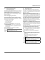
The intelligent wiring method used by Inline terminals
enables the station to be created quickly and easily, since,
e.g., time-consuming wiring of the terminal power supply is
not required.
In the simplest case, it is only necessary for the power
supply units integrated in the bus coupler to be supplied with
24 V DC on the input side. They then generate the required
operating voltages for the bus coupler and the connected
Inline terminals.
The end plate is supplied with the bus coupler. Place this
plate at the end of the Inline station. The end plate has no
electrical function. It protects the station from ESD pulses
and the user from dangerous contact voltage.
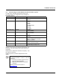
Table of contents
1
Description.................................................................................................................................. 1
2
Ordering data.............................................................................................................................. 3
3
Technical data ............................................................................................................................ 4
4
Basic circuit diagram................................................................................................................... 7
5
Local diagnostic and status indicators ........................................................................................ 8
6
Connecting Modbus, power supply, actuators, and sensors....................................................... 9
6.1
6.2
6.3
Connecting Modbus ....................................................................................................................................... 9
Mains termination resistors............................................................................................................................. 9
Terminal point assignment of input and output connectors........................................................................... 10
7
Connection example..................................................................................................................10
8
Notes on using the terminal in potentially explosive areas .........................................................11
9
Startup .......................................................................................................................................12
10 Hardware configuration..............................................................................................................12
10.1
10.2
10.3
10.4
10.5
Address setting ............................................................................................................................................ 12
Parameterization via rotary encoding switches............................................................................................. 12
Parameterizing the IL MOD BK DI8 DO4-PAC via Modbus registers ........................................................... 13
Modbus telegram watchdog (connection monitoring)................................................................................... 14
Plug and play mode...................................................................................................................................... 14
11 Modbus protocol........................................................................................................................15
12 Modbus functions ......................................................................................................................16
13 Examples for Modbus functions.................................................................................................17
14 Modbus tables ...........................................................................................................................23
14.1
14.2
14.3
7258_en_03
Process data ................................................................................................................................................ 23
Special registers........................................................................................................................................... 25
Description of special registers..................................................................................................................... 25
PHOENIX CONTACT
2
IL MOD BK DI8 DO4-PAC
2
Ordering data
Product
Description
Inline bus coupler for Modbus RTU/ASCII with eight digital inputs and four
digital outputs; complete with accessories (end plate, Inline connector, and
labeling fields)
Accessories: Additional system components
Description
Type
Order No.
Pcs./Pkt.
IL MOD BK DI8 DO4-PAC
2878696
1
Type
Order No.
Pcs./Pkt.
Pcs./Pkt.
FO interface converters for fiber optic data conversion and transmission (see INTERFACE catalog)
Power supply units for supplying the bus coupler (see INTERFACE catalog)
Accessories: Connectors
Description
Type
Order No.
SUBCON connector
SUBCON-PLUS-MODBUS/IL/BK
2310808
1
Connector set for Inline bus coupler with aligned I/Os (as replacement item)
IL BKDIO-PLSET
2778599
1
Accessories: Other
Description
Type
Order No.
Pcs./Pkt.
Quick mounting end clamp for securing the module/Inline station on the DIN
rail for a horizontal mounting position; to the right and left of the module/Inline
station
CLIPFIX 35-5
3022276
50
End clamp for securing the module/the Inline station on the DIN rail for a
vertical mounting position; above and below the module/Inline station
E/AL-NS 35
1201662
10
Keying profile
IL CP
2878696
100
Zack marker strip to label the terminals
ZB 6 ... see CLIPLINE catalog
ZB 12 ... see CLIPLINE catalog
DIN EN 50022 DIN rail, 2 meters
NS 35/7,5 PERF
NS 35/7,5 UNPERF
0801733
0801681
1
1
Description
Type
Order No.
Pcs./Pkt.
"I/O terminals at bus couplers" application note
AH IL BK IO LIST
9015358
1
"Automation terminals of the Inline product range" user manual
IL SYS INST UM E
2698737
1
"Inline terminals for use in zone 2 potentially explosive areas"
application note
AH EN IL EX ZONE 2
7217
1
"Peripherals Communication Protocol (PCP)" user manual
IBS SYS PCP G4 UM E
2745169
1
"Firmware services and error messages" user manual
IBS SYS FW G4 UM E
2745185
1
"Hardware and firmware manual for the FL IL 24 BK/FL IL 24 BK-PAC
Ethernet/Inline bus terminal" user manual
FL IL 24 BK-PAC UM E
9014205
1
Documentation
7258_en_03
PHOENIX CONTACT
3
IL MOD BK DI8 DO4-PAC
3
Technical data
General data
Housing dimensions (width x height x depth)
80 mm x 119.8 mm x 71.5 mm
Weight
320 g (with connectors)
Ambient temperatures (operation)
-25°C ... +60°C
Ambient temperature (storage)
-45°C ... +85°C
Humidity (operation/storage/transport)
10% ... 95% (according to DIN EN 61131-2)
Air pressure (operation/storage/transport)
70 kPa to 106 kPa (up to 3000 m above sea level)
Degree of protection
IP20
Protection class
Class III according to EN 61131-2, IEC 61131-2
Response time (aligned I/Os)
4 ms, typical
Connection data
Designation
Inline I/O connector
Connection method
Spring-cage connection
Conductor cross-section
0.08 mm2 ... 1.5 mm2 (solid or stranded), 28 - 16 AWG
Conductor cross section [AWG]
28 ... 16
Interface: Inline local bus
Connection method
Inline data jumpers
Transmission speed
500 kbps, 2 Mbps (automatic detection, no combined system)
Interface: Modbus
Connection method
9-pos. D-SUB female connector (electrically isolated supply; shielding directly
connected to functional earth ground)
Number of positions
9
Transmission speed
1.2 kbps to 115.2 kbps (configurable)
System data of the bus coupler
Number of supported devices
63, maximum (per station)
Number of connectable local bus devices
61, maximum (on board I/Os are two devices)
Number of devices with parameter channel (PCP)
8, maximum
Supply voltage for UBK, US, UM
Recommended cable lengths
30 m, maximum; do not route cable through outdoor areas
Continuation
Through potential routing
Nominal value
24 V DC
Permissible range (according to EN 61131-2)
19,2 V to 30 V (ripple included)
NOTE: Electronics may be damaged when overloaded
Provide external fuses for the 24 V areas UL, US, and UM. The power supply unit must be able to supply four times the nominal current of the
external fuse, to ensure that it trips in the event of an error.
Communications power UL (7.5 V) and the analog supply UANA (24 V) are generated from the bus coupler supply UBK.
Power consumption
Current consumption from UL (7.5 V)
0.07 mA, typical/0.8 A, maximum
Current consumption from US (24 V)
8 A, maximum
Current consumption from UM (24 V)
8 A, maximum
Current consumption from UANA (24 V)
0.5 A, maximum
Power dissipation
1.7 W, typical
7258_en_03
PHOENIX CONTACT
4
IL MOD BK DI8 DO4-PAC
Digital inputs
Number
8
Connection method for sensors
2 and 3-wire technology
Input design
According to EN 61131-2 Type 1
Definition of switching thresholds
Maximum low-level voltage
ULmax < 5 V
Minimum high-level voltage
UHmin > 15 V
Common potentials
Sensor supply US, ground
Nominal input voltage UIN
24 V DC
Permissible range
-30 V < UIN < +30 V DC
Nominal input current for UIN
3 mA, typical
Current flow
Limited to 3 mA, maximum
Response time
1.2 ms, typical
Permissible cable length to the sensor
100 m
Digital outputs
Number
4
Connection method for actuators
2 and 3-wire technology
Nominal output voltage UOUT
24 V DC
Differential voltage at Inom
<1V
Nominal current Inom per channel
0.5 A
Total current
2A
Nominal load
Ohmic
12 W
Lamp
12 W
Inductive
12 VA (1.2 H)
Switching frequency with nominal inductive load
0.5 Hz (1.2 H), maximum
Response time
1.2 ms, typical
Overload response
Auto restart
Response with inductive overload
Output may be damaged
Reverse voltage protection against short pulses
Protected against reverse voltages
Resistance to permanently applied reverse voltages
Protected against reverse voltages, permissible current 2 A, maximum
Response upon power down
The output follows the supply voltage without delay.
Limitation of the voltage induced on circuit interruption
-30.0 V, approximately
Maximum output current when switched off
10 µA (When not loaded, a voltage can be measured even at an output that is
not set.)
Protection
Supply
Surge voltage, polarity reversal
Suppressor diode parallel to supply voltage
Digital inputs
Polarity reversal
Diode for protection against polarity reversal
Digital outputs
Short circuit protection, overload protection
Free running circuit
Error messages to the higher-level control or computer system
Short circuit/overload of the digital outputs
Yes
Sensor supply not present
Yes
Mechanical tests
Vibration resistance according to IEC 60068-2-6
5g
Shock test according to IEC 60068-2-27
Operation: 25g, 11 ms period, half-sine shock pulse
7258_en_03
PHOENIX CONTACT
5
IL MOD BK DI8 DO4-PAC
Conformance with EMC directive 2004/108/EC
Noise immunity test according to EN 61000-6-2
Electrostatic discharge (ESD)
EN 61000-4-2/
IEC 61000-4-2
Criterion B
6 kV contact discharge
8 kV air discharge
Electromagnetic fields
EN 61000-4-3
IEC 61000-4-3
Criterion A
Field strength: 10 V/m
Fast transients (burst)
EN 61000-4-4/
IEC 61000-4-4
Criterion A
All interfaces: 1 kV
Criterion B
All interfaces: 2 kV
Surge voltage
EN 61000-4-5/
IEC 61000-4-5
Criterion B
DC supply lines:
0.5 kV/1 kV (symmetrical/asymmetrical)
Fieldbus cable shielding 1 kV
Conducted interference
EN 61000-4-6
IEC 61000-4-6
Criterion A
Test voltage 10 V
Noise emission test according to EN 61000-6-4
Noise emission of housing
EN 55011
Class A
Approvals
For the latest approvals, please visit www.phoenixcontact.net/download.
7258_en_03
PHOENIX CONTACT
6
IL MOD BK DI8 DO4-PAC
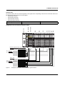
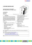
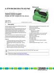
4
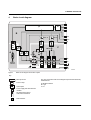
Basic circuit diagram
IB
µP
B
DO1...4
DI1...8
U L+
UANA
UL
RS485
5V
8x DI
7.5 V
A
7.5 V
24 V
24 V
24 V
C
4x
DO
US
UM
UBK
US
US
UM
Modbus
interface
PWR
7258C004
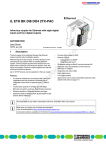
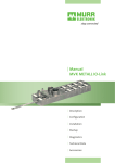
Figure 1
Basic circuit diagram for the bus coupler
Key:
µ P
Microprocessor
The gray areas in the basic circuit diagram represent the electrically
isolated areas:
IB
Protocol chip
A: Modbus interface
B: Logic
C: I/O
Optocoupler
Power supply unit with electrical
isolation
RS-485 interface driver
with electrical isolation
RS
485
PNP transistor
7258_en_03
PHOENIX CONTACT
7
IL MOD BK DI8 DO4-PAC
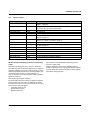
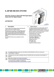
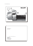
5
Local diagnostic and status indicators
MODBUS
PWR
I2
PWR
UL TR
US CO
UM WD
5 6
7 8
I2
I2
C
4-PA
DO
DI8 6
D BK 7869
IL MONo.: 28
CII
erOrd
/AS
MO
DB
US
AD
10
DR
U
RT
E
0 2
4
14
12
I1
O1
PWR
TR
UL
CO
US D
W
UM
SS
0 2
4
6
D
E
2
1
4
3
2
1
4
3
7
5
8
6
I1
98
x1
6
8
0
x1
MODBUS
1 2
3 4
O1
D E
X1
1 2
3 4
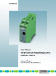
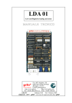
Figure 2
I1
O1
Indicators on the bus coupler
LED
PWR
UL
Color
Meaning
State
Description of the LED states
Green
ULogic
US
Green
USegment
UM
Green
UMain
TR
Yellow
TRaffic
CO
Red
COnfiguration
WD
Red
WatchDog
ON
OFF
ON
OFF
ON
OFF
ON
OFF
ON
OFF
ON
24 V bus coupler supply/7.5 V communications power present
24 V bus coupler supply/7.5 V communications power not present
24 V segment circuit supply present
24 V segment circuit supply not present
24 V I/O supply present
24 V I/O supply not present
Data exchange at the RTU/ASCII interface
No data exchange at the RTU/ASCII interface
The active station configuration differs from the saved configuration
The active station configuration matches the saved configuration.
Time between two Modbus telegrams exceeded during active connection
monitoring (Modbus telegram watchdog)
On power on reset:
Reading in new parameters
On power on reset:
Parameters transferred successfully
On power on reset:
Parameters not transferred
No error
Flashing
at 2 Hz
Flashing
at 0.5 Hz
Flashing
at 5 Hz
OFF
7258_en_03
PHOENIX CONTACT
8
IL MOD BK DI8 DO4-PAC
LED
O1
D
Color
Meaning
State
Green
Diagnostics
E
Red
Error
1-4
Yellow
Output 1
to
output 4
ON
Flashing
at 0.5 Hz
ON
OFF
ON
OFF
I1, I2
1-8
Yellow
Input 1 to
input 8
ON
OFF
Description of the LED states
Data transmission active within the station
Data transmission not active within the station
Short circuit/overload of local outputs
No short circuit/overload of local outputs
Outputs are active
Outputs are not active
Inputs are active
Inputs are not active
Error message sent to the higher-level control system
–
–
Sensor supply not present (peripheral fault)
Short circuit/overload at an output (peripheral fault)
See also "Local bus diagnostic status register (7997)" on
page 27.
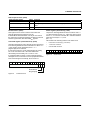
6
Connecting Modbus, power supply, actuators, and sensors
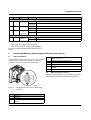
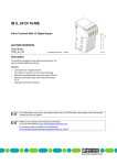
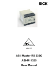
6.1
Connecting Modbus
4
Connect Modbus to the bus coupler using a 9-pos. D-SUB
connector (see "Ordering data" on page 3). For the pin
assignment, please refer to the figure and the table.
9
I2
4-PAC
DO
DI8 6
D BK 7869
IL MOr-No.: 28
CII
Orde
/AS
MO
DB
U
RT
US
AD
12
10
DR
ES
0 2
4
14
S
0 2
4
6
TR
UL
CO
US D
W
UM
D
E
2
1
4
3
2
1
4
3
7
5
8
6
6.2
Mains termination resistors
98
x1
6
8
0
MODBUS
X1
5
4
3
2
1
9
8
7
6
MODBUS
x1
I1
O1
PWR
5
6
7
8
CNTR-P (control signal for repeater),
direction control
DGND (reference potential to 5 V)
VCC
Reserved
RxD/TxD-N (receive/transmit data –),
cable A
Reserved
The use of this SUBCON connector ensures that the cable
termination meets the Modbus RTU/ASCII specification.
X1
7258B002
Figure 3
Pin
1
2
3
Pin assignment of the 9-pos. D-SUB female
connector
Assignment
Reserved
Reserved
RxD/TxD-P (receive/transmit data +),
cable B
7258_en_03
PHOENIX CONTACT
9
IL MOD BK DI8 DO4-PAC
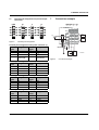
6.3
1.1
1.2
1.3
1.4
Terminal point assignment of input and output
connectors
PWR
O1
I1
I2
1.1 2.1
1.1 2.1
1.1 2.1
3.1 4.1
1
1
1.2 2.2
2
2
1.3 2.3
3
3
1.4 2.4
4
4
2.1
1.1
2.2
1.2
2.3
1.3
2.4
1.4
1
1
1.2 2.2
2
2
1.3 2.3
3
3
1.4 2.4
4
1
4
2.1
1.1
2.2
1.2
2.3
1.3
2.4
1.4
2
1
1
1.2 2.2
2
2
1.3 2.3
3
3
1.4 2.4
4
4
2.1
3.1
2.2
3.2
2.3
3.3
2.4
3.4
1
1
3.2 4.2
2
2
3.3 4.3
3
3
3.4 4.4
4
3
4
7
Connection example
1
2
3
4
4.1
4.2
US U M
4.3
4.4
4
UL
IN 6
+24 V
+
-
+24 V
IN 7
Figure 4
Terminal point assignment
Terminal point assignment of the power connector (1)
Terminal
points
US
2.1
UL
2.2
GND UL
2.3
Functional earth 2.4
ground (FE)
Assignment
UM
UM
GND UM, US
Functional earth
ground (FE)
Modbus
-
Assignment
+
Terminal
points
1.1
1.2
1.3
1.4
UM
OUT
3
Figure 5
OUT
2
7258A005
Connection example
Terminal point assignment of the output connector (2)
Terminal
points
1.1
1.2
1.3
1.4
Assignment
OUT1
PGND
FE
OUT3
Terminal
points
2.1
2.2
2.3
2.4
Assignment
OUT2
PGND
FE
OUT4
Terminal point assignment of the input connector (3)
Terminal
points
1.1
1.2
1.3
1.4
Assignment
IN1
US
PGND
IN3
Terminal
points
2.1
2.2
2.3
2.4
Assignment
IN2
US
PGND
IN4
Terminal point assignment of the input connector (4)
Terminal
points
3.1
3.2
3.3
3.4
7258_en_03
Assignment
IN5
US
PGND
IN7
Terminal
points
4.1
4.2
4.3
4.4
Assignment
IN6
US
PGND
IN8
PHOENIX CONTACT
10
IL MOD BK DI8 DO4-PAC
8
Notes on using the terminal in potentially explosive areas
Installation in zone 2
WARNING: Explosion hazard
1.
Before startup, ensure that the following points
and instructions have been observed.
2.
Approval according to EC directive 94/9
II 3G Ex nA IIC T4 X
3.
Installation notes
1.
2.
3.
4.
5.
6.
7.
8.
9.
This Inline terminal can be installed in zone 2.
The Inline terminal must only be installed, operated,
and maintained by qualified personnel.
Please follow the installation instructions given in the
IL SYS INST UM E user manual and the package slip.
When installing and operating the device, the
applicable safety directives (including national safety
directives), accident prevention regulations, as well as
general technical regulations, must be observed.
Please refer to the corresponding documentation (user
manual, data sheet, package slip) and the certificates
(EC type examination and other approvals, if
applicable) for safety-related data.
It is not permitted to access the circuits inside the Inline
terminal. Do not repair the Inline terminal by yourself but
replace it with a terminal of the same type. Repairs may
only be carried out by the manufacturer.
IP20 (EN 60529) protection of the device is provided for
a clean and dry environment.
Do not subject the Inline terminal to mechanical strain
and/or thermal loads, which exceed the limits specified
in the product documentation.
The Inline terminal has not been designed for use in
potentially dust-explosive atmospheres.
7258_en_03
4.
Observe the specified conditions for use in potentially
explosive areas.
When installing the terminal, use an appropriate and
approved housing with a minimum protection of IP54.
Please observe the EN 60079-14 requirements, e.g., a
steel housing with a wall thickness of 3 mm.
In potentially explosive areas, only snap the Inline
terminal onto the rail and connect the cables when the
power is switched off.
In zone 2, only connect devices to the supply and signal
circuits that are suitable for operation in potentially
explosive areas of zone 2 and the conditions at the
installation location.
Restrictions/limit values
1.
2.
3.
4.
Only Inline terminals that are approved for use in
potentially explosive areas may be snapped next
to this Inline terminal. Before using an Inline terminal
in a zone 2 potentially explosive area, first check that
the terminal has been approved for installation in this
area. For a list of terminals that are approved for the
potentially explosive areas of zone 2, please refer to the
AH EN IL EX ZONE 2 application note.
Please make sure that the maximum permissible
current of 4 A flowing through potential jumpers UM
and US (total current) is not exceeded when using the
Inline terminals in potentially explosive areas.
The supply of UM and US at the bus coupler must not
exceed 4 A.
Also ensure that the maximum permissible current
of 2 A flowing through potential jumper UL is not
exceeded.
PHOENIX CONTACT
11
IL MOD BK DI8 DO4-PAC
9
Startup
Default upon delivery/default settings
By default upon delivery, the following functions and
features are available:
Configuration of the RS-485 interface
- Transmission mode
RTU
- Baud rate
19200 bps
- Data bits
8
- Parity
Even
- Stop bits
1
Modbus telegram watchdog
10000 ms
(connection monitoring)
Plug and play mode
Enabled
Fault response mode
Reset fault mode
reset. "Parameter setting" mode is assumed when the
address switch for tens is set to a position that is not
assigned to an address, i.e., ≥ 10.
Tens switch (x10)
Position 10
(Transmission mode,
factory configuration,
plug and play mode
(P&P))
Position 11 (baud rate)
Position 12 (data bits)
10
Hardware configuration
10.1
Address setting
The address is set using two rotary encoding switches. The
left switch is used to set the position in tens and the right
switch is used to set the position in units. Addresses can be
set between 1 and 99. The figure shows the address setting
"74".
Position 13 (parity)
Position 14 (stop bits)
Position 15 (watchdog)
Units switch (x1)
Position 0: RTU (default)
Position 1: ASCII
Position 2: Factory
configuration
Position 3: P&P ON (default)
Position 4: P&P OFF
Position 0: 1200
Position 1: 2400
Position 2: 4800
Position 3: 9600
Position 4: 19200 (default)
Position 5: 38400
Position 6: 57600
Position 7: 115200
Position 0: 7 bits
Position 1: 8 bits (default)
Position 0: None
Position 1: Even (default)
Position 2: Odd
Position 0: 1 bit (default)
Position 1: 2 bits
Position 0: ON (default)
Position 1: OFF
By default upon delivery as well as after a
reset to factory configuration, the parameters
labeled "default" in the table are set.
I2
4-PAC
DO
DI8 6
D BK 7869
IL MOr-No.: 28
CII
Orde
/AS
MO
DB
U
AD
10
E
DR
0 2
4
14
12
TU
SR
PWR
SS
0 2
4
6
TR
UL
CO
US
WD
UM
D
E
2
1
4
3
2
1
4
3
7
5
8
6
In the event of a power on reset (voltage reset), only the set
operating parameter is read in and stored. To set several
parameters, this procedure must be repeated for each
individual parameter.
98
x1
6
8
x1
I1
O1
0
MODBUS
X1
14
While reading in a parameter, the watchdog LED flashes
quickly (2 Hz). If the parameter has been accepted, the
watchdog LED flashes slowly (0.5 Hz). If the parameter is
invalid, the watchdog LED flashes very quickly (5 Hz).
12
10
x1
Figure 6
ADDRESS rotary encoding switches
A valid address is applied on power up. It cannot be
modified during operation.
10.2
Example: The following is to be set: "Plug and play OFF"
and "ASCII".
•
Set "Plug and play OFF" first.
•
Execute a voltage reset.
•
After the parameter has been accepted, set "ASCII".
•
Execute a voltage reset again.
Parameterization via rotary encoding switches
In addition to the address, various operating parameters can
also be set via these rotary encoding switches. The
operating parameters are only read in following a power on
7258_en_03
PHOENIX CONTACT
12
IL MOD BK DI8 DO4-PAC
10.3
Parameterizing the IL MOD BK DI8 DO4-PAC via Modbus registers
In addition to the described setting options using rotary
encoding switches, the configuration can be modified via
the Modbus registers.
Register
2100 (16-bit word)
Parameter
Transmission mode
2101 (16-bit word)
Baud rate
2102 (16-bit word)
Data bits
2103 (16-bit word)
Parity
2104 (16-bit word)
Stop bits
1280 (16-bit word)
Watchdog
2002 (16-bit word)
Fault response mode
2006 (16-bit word)
Command register
Value
0: RTU (default)
1: ASCII
0: 1200
1: 2400
2: 4800
3: 9600
4: 19200 (default)
5: 38400
6: 57600
7: 115200
0: 7 bits
1: 8 bits (default)
0: None
1: Even (default)
2: Odd
0: 1 bit (default)
1: 2 bits
0: Watchdog deactivated
200 ms to 65000 ms (1 ms steps)
10000 ms (default)
0: Standard fault mode
1: Reset fault mode (default)
1: Enable plug and play mode (default)
0: Disable plug and play mode
The new parameters are applied following a positive
response. This response is transmitted again with the "old"
parameters. The next request is then made with the new
parameters.
Default values: 19200 baud, 8 data bits, even parity, 1 stop
bit, 10000 ms watchdog
Following a power up, the last valid parameter record
applies.
When the baud rate changes, the RTU framing
also changes by default, i.e., times t 1.5 and t 3.5
are adjusted.
t 1.5 = Maximum permissible gap between the
bytes of a Modbus telegram
t 3.5 = Minimum pause between two Modbus
telegrams
Detailed information can be found at:
www.modbus.org.
7258_en_03
PHOENIX CONTACT
13
IL MOD BK DI8 DO4-PAC
10.4
Modbus telegram watchdog
(connection monitoring)
The watchdog monitors Modbus telegrams and is triggered
each time a Modbus telegram is received correctly. It can be
enabled and disabled via the rotary encoding switches, see
"Parameterization via rotary encoding switches" on
page 12. The time can be set via register 1280 (0 = disabled;
200 ms to 65000 ms).
Actions after triggering the watchdog
The action taken when the watchdog is triggered depends
on the set fault response mode. By default upon delivery,
the fault response mode is set to reset fault mode. For reset
fault mode, the following applies:
– Set digital outputs to zero
– Freeze analog outputs
– Watchdog LED ON
Special feature when disabling the watchdog via write
access to register 1280:
– Settings modified by write access (disable watchdog,
modify monitoring time) are only applied following a
power up reset.
Watchdog activation via register 1280 is applied
immediately during operation.
The Modbus telegram watchdog does not
operate during plug and play mode.
10.5
Plug and play mode
The IL MOD BK DI8 DO4-PAC supports plug and play
mode (P&P). This mode enables Inline terminals connected
in the field to be started up using the bus coupler without a
higher-level computer.
P&P mode can be enabled and disabled with the ADDRESS
switches (see "Parameterization via rotary encoding
switches" on page 12). The switch position is mapped to the
command register (Modbus register 2006) (see page 26).
By default upon delivery, P&P mode is activated. The P&P
mode status (active or inactive) is stored retentively on the
bus coupler. In P&P mode, the connected Inline terminals
are detected and their function checked. If this physical
configuration is ready for operation, it is stored retentively on
the bus coupler as a reference configuration.
P&P mode must be deactivated again so that the reference
configuration is not overwritten the next time the bus coupler
is started. At the same time, the deactivation of P&P mode
also acknowledges the reference configuration and enables
process data exchange.
When P&P mode is deactivated, the reference configuration
is compared to the physical configuration. If they are the
same, the bus coupler can be set to the "RUN" state.
If the reference configuration and the physical configuration
differ, the CO LED lights up and process data exchange is
no longer possible for safety reasons.
In order to operate the bus you have the following two
options:
1. Restore the original configuration so that the reference
configuration and the physical configuration are the
same again
2. Activate P&P mode so that the active physical
configuration is accepted as the reference
configuration.
If plug and play mode is disabled, the bus is only
started up if the configuration of the connected
bus matches the saved configuration.
If plug and play mode is enabled, the writing of
process data is rejected by an exception. Read
access to the process data is possible.
7258_en_03
PHOENIX CONTACT
14
IL MOD BK DI8 DO4-PAC
11
Modbus protocol
Additional
Address
Client
Function
Code
Data
Error Check
Server
Initiate Request
PDU
ADU
Function Code Data Request
Error Detected in the Action
Initiate an Error
7258A018
Figure 7
Modbus protocol
Exception
Function Code
Exception
Code
Key:
Receive the Response
PDU
ADU
Protocol data unit
Application data unit (protocol frame)
The Modbus application protocol is created by the client that
initiates a Modbus transmission.
The function code field of the protocol (1 byte) informs the
server of which action it is to perform.
The data fields of messages, which are sent from a client to
a server, contain additional information that the server uses
in order to perform the action specified by the function code
field. This includes, e.g., digital addresses and register
addresses, the number of units to be managed, and the
number of actual data bytes.
Client
Server
7258A017
Figure 9
Modbus transmission (exception response)
Key:
Client
Server
Control system
Modbus devices
For an exception response, the server returns a code that
corresponds to the original function code of the request
PDU, whereby the MSB is set to logic 1.
There are two different transmission modes: RTU and
ASCII. Both differ in terms of the type and form of
information represented in a telegram. In a Modbus
network, each device must have the same transmission
mode.
Initiate Request
Modbus RTU
Modbus RTU telegrams consist of the following parts:
Function Code Data Request
Perform the Action
Initiate the Response
Function Code Data Response
Receive the Response
7258A016
Figure 8
Modbus transmission (without errors)
Function
Data
CRC
1 byte
0 - 252 bytes
2 bytes
Modbus RTU telegrams are separated by breaks known as
end of frame times. The time is at least 3.5 times the time of
a sent character. It cannot be adjusted.
The advantage the RTU transmission mode offers over the
ASCII transmission mode is a higher data throughput with
the same baud rate.
Key:
Client
Server
Station
address
1 byte
Control system
Modbus devices
If no error occurs in a correctly received Modbus protocol for
the requested Modbus function, the data field for a response
from a server to a client contains the requested data.
When the server responds to the client, it uses the function
code field to indicate either a normal (error-free) response or
to indicate an error (this is also known as an exception
response). For a normal response, the server returns the
original function code to the request.
7258_en_03
PHOENIX CONTACT
15
IL MOD BK DI8 DO4-PAC
Modbus ASCII
Modbus ASCII telegrams consist of the following parts:
Start
1 character (:)
Station address
2 characters
Function
2 characters
The transmitted characters comprise the ASCII code and
consist of 1 byte each.
The advantage the ASCII transmission mode offers over the
RTU transmission mode is non-time-critical data
12
Data
0 - 2 x 252
characters
LRC
2 characters
END
2 characters
(CR, LF)
transmission.
The frame start (:) and end (CR, LF) are specified using
special characters. Gaps between the bytes of a frame are
not important.
Modbus functions
The Modbus protocol functions determine whether data is to
be written or read and what type of data is involved.
The following Modbus functions are supported:
Code No.
fc1
fc2
fc3
fc4
fc5
fc6
fc15
fc16
Function code
Read coils
Read input discretes
Read multiple registers
Read input registers
Write coil
Write single register
Write multiple coils
Write multiple registers
Description
Read digital outputs
Read digital inputs
Read a multiple register (e.g., read back analog output)
Read an input register (e.g., analog input)
Write a digital output bit
Write an output register (e.g., analog output)
Write multiple digital outputs
Write multiple output registers
For additional information about Modbus
functions, please refer to the
FL IL 24 BK-PAC UM E user manual.
7258_en_03
PHOENIX CONTACT
16
IL MOD BK DI8 DO4-PAC
13
Examples for Modbus functions
Function code fc1
Request
Function code
Start address
Number of outputs
1 byte
2 bytes
2 bytes
01hex
0000hex ... FFFFhex
1 ... 2000 (7D0hex)
Response
Function code
1 byte
01hex
Number of bytes
1 byte
N*
Output status
n bytes
n = N or N+1
*N = (Number of outputs)/8; if the remainder is > 0: N = N+1
Error
Function code
Exception code
1 byte
1 byte
Function code + 80hex
01 or 02 or 03 or 04
Example for a request to read digital outputs 20 ... 38 38
Request
Response
Field name
(Hex)
Field name
Function
01
Function
Start address (high)
00
Number of bytes
Start address (low)
13
Output status 27 ... 20
Number of outputs (high)
00
Output status 35 ... 28
Number of outputs (low)
13
Output status 38 ... 36
(Hex)
01
03
CD
6B
05
Function code fc2
Request
Function code
Start address
Number of outputs
1 byte
2 bytes
2 bytes
02hex
0000hex ... FFFFhex
1 ... 2000 (7D0hex)
Response
Function code
1 byte
01hex
Number of bytes
1 byte
N*
Output status
N* x 1 byte
*N = (Number of inputs)/8; if the remainder is > 0: N = N+1
Error
Error code
1 byte
Modbus Application Protocol Specification V1.1a
Exception code
1 byte
7258_en_03
82hex
01 or 02 or 03 or 04
PHOENIX CONTACT
17
IL MOD BK DI8 DO4-PAC
Example for a request to read digital inputs 197 ... 218
Request
Response
Field name
(Hex)
Field name
Function
02
Function
Start address (high)
00
Number of bytes
Start address (low)
C4
Input status 27 ... 20
Number of inputs (high)
00
Input status 35 ... 28
Number of inputs (low)
16
Input status 38 ... 36
(Hex)
02
03
AC
DB
35
Function code fc3
Request
Function code
Start address
Number of registers
Response
Function code
Number of bytes
Register values
*N = Number of registers
Error
Error code
Exception code
1 byte
2 bytes
2 bytes
1 byte
1 byte
N* x 1 byte
1 byte
1 byte
03hex
0000hex ... FFFFhex
1 ... 125 (7Dhex)
03hex
2 x N*
83hex
01 or 02 or 03 or 04
Example for a request to read registers 108 ... 110
Request
Response
Field name
(Hex)
Field name
Function
03
Function
Start address (high)
00
Number of bytes
Start address (low)
6B
Register value (high) (108)
Register number (high)
00
Register value (low) (108)
Register number (low)
03
Register value (high) (109)
Register value (low) (109)
Register value (high) (110)
Register value (low) (110)
7258_en_03
(Hex)
03
06
02
2B
00
00
00
64
PHOENIX CONTACT
18
IL MOD BK DI8 DO4-PAC
Function code fc4
Request
Function code
Start address
Number of input registers
Response
Function code
Number of bytes
Input registers
*N = Number of input registers
Error
Error code
Exception code
1 byte
2 bytes
2 bytes
1 byte
1 byte
N* x 2 byte
1 byte
1 byte
Example for a request to read input register 9
Request
Field name
(Hex)
Function
04
Start address (high)
00
Start address (low)
08
Number of input registers (high)
00
Number of input registers (high)
01
04hex
0000hex ... FFFFhex
0001hex ... 007Dhex
04hex
2 x N*
84hex
01 or 02 or 03 or 04
Response
Field name
Function
Number of bytes
Input register 9 (high)
Input register 9 (low)
(Hex)
04
02
00
0A
Function code fc5
Request
Function code
Output address
Output value
1 byte
2 bytes
2 bytes
05hex
0000hex ... FFFFhex
0000hex ... FF00hex
Response
Function code
Output address
Output value
1 byte
2 bytes
2 bytes
05hex
0000hex ... FFFFhex
0000hex ... FF00hex
Error
Error code
Exception code
1 byte
1 byte
85hex
01 or 02 or 03 or 04
7258_en_03
PHOENIX CONTACT
19
IL MOD BK DI8 DO4-PAC
Example for a request to write output 173 ON
Request
Field name
(Hex)
Function
05
Output address (high)
00
Output address (low)
AC
Output value (high)
FF
Output value (low)
00
Response
Field name
Function
Output address (high)
Output address (low)
Output value (high)
Output value (low)
(Hex)
05
00
AC
FF
00
Function code fc6
Request
Function code
Register address
Register value
1 byte
2 bytes
2 bytes
06hex
0000hex ... FFFFhex
0000hex ... FFFFhex
Response
Function code
Register address
Register value
1 byte
2 bytes
2 bytes
06hex
0000hex ... FFFFhex
0000hex ... FFFFhex
Error
Error code
Exception code
1 byte
1 byte
86hex
01 or 02 or 03 or 04
Example for a request to write register 2 to 0003hex
Request
Response
Field name
(Hex)
Field name
Function
06
Function
Register address (high)
00
Register address (high)
Register address (low)
01
Register address (low)
Register value (high)
00
Register value (high)
Register value (low)
03
Register value (low)
7258_en_03
(Hex)
06
00
01
00
03
PHOENIX CONTACT
20
IL MOD BK DI8 DO4-PAC
Function code fc15
Request PDU
Function code
1 byte
0Fhex
Start address
2 bytes
0000hex ... FFFFhex
Number of outputs
2 bytes
0001hex ... 07B0hex
Byte counter
1 byte
N*
Output value
N* x 1 byte
*N = (Number of outputs)/8; if the remainder is > 0: N = N+1
Response PDU
Function code
Start address
Number of outputs
1 byte
2 bytes
2 bytes
0Fhex
0000hex ... FFFFhex
0001hex ... 07B0hex
Error
Error code
Exception code
1 byte
1 byte
8Fhex
01 or 02 or 03 or 04
Example for a request to write a series of 10 outputs, starting with output 20
The request data contains two bytes. The binary values are assigned to the outputs as follows:
Byte (hex)
CD
01
Bit
1
1
0
0
1
1
0
1
0
0
0
0
0
0
0
1
Output
27 26 25 24 23 22 21 20
29 28
The first transmitted byte (CDhex) addresses outputs 27 to 30, whereby the LSB in this setting
addresses output 20.
The next transmitted byte (01hex) addresses outputs 29 and 28, whereby the LSB in this setting
addresses output 28. In the last data byte, unused bits should be filled with zeros.
Request
Field name
Function
Start address (high)
Start address (low)
Number of outputs (high)
Number of outputs (low)
Byte counter
Output value (high)
Output value (low)
7258_en_03
(Hex)
0F
00
13
00
0A
02
CD
01
Response
Field name
Function
Start address (high)
Start address (low)
Number of outputs (high)
Number of outputs (low)
(Hex)
0F
00
13
00
0A
PHOENIX CONTACT
21
IL MOD BK DI8 DO4-PAC
Function code fc16
Request
Function code
Start address
Number of registers
Byte counter
Register value
*N = Number of registers
1 byte
2 bytes
2 bytes
1 byte
N* x 2 bytes
10hex
0000hex ... FFFFhex
0001hex ... 0078hex
2 x N*
Value
Response
Function code
Start address
Number of registers
1 byte
2 bytes
2 bytes
10hex
0000hex ... FFFFhex
1 ... 123 (78hex)
Error
Error code
Exception code
1 byte
1 byte
90hex
01 or 02 or 03 or 04
Example for a request to write two registers, starting with 2 to
000Ahex and 0102hex
Request
Response
Field name
(Hex)
Field name
Function
10
Function
Start address (high)
00
Start address (high)
Start address (low)
01
Start address (low)
Number of registers (high)
00
Number of registers (high)
Number of registers (low)
02
Number of registers (low)
Byte counter
04
Register value (high)
00
Register value (low)
0A
Register value (high)
01
Register value (low)
02
7258_en_03
(Hex)
10
00
01
00
02
PHOENIX CONTACT
22
IL MOD BK DI8 DO4-PAC
14
Modbus tables
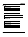
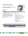
14.1
Process data
The Modbus register tables provide information about the location of process data in the control system. Generally, the bitoriented process data appears first in the registers followed by the byte-oriented process data.
Static table
Modbus register table
0 - 191 (16-bit word)
192 - 383 (16-bit word)
384 - 575 (16-bit word)
576 - 767 (16-bit word)
Digital Modbus
inputs table
0 - 3071 (bits)
–
–
–
Digital Modbus
outputs table
–
–
0 - 3071 (bits)
–
Internal IL MOD BK
tables
Digital inputs
Analog inputs
Digital outputs
Analog outputs
Function codes
that can be used
fc2
fc4
fc1, fc5, fc15
fc3, fc6, fc16
IL MOD BK DI8 DO4-PAC
Order-No.: 2878696
PWR
O1
I1
AO2
AO1
AI2
AI2
DI2
DI8
DO2
DO8
DI8 ETH BK
MOD BK
DO4 ETH BK
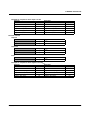
Assignment of the process data in static tables
I2
D E
MODBUS RTU/ASCII
UL TR
US CO
UM WD
1
3
2
4
1
3
2
4
5 7
6 8
ADDRESS
0
2
14
12
4
10
6
9 8
x10
x1
MODBUS
X1
Modbus register/location of process data
DATA IN
DI
AI
Address 0000
Address 0001
Address 0002
Address 0192
Byte-oriented
Address 0193
Address 0194
Address 0195
Address 0196
Address 0197
Bit-oriented
xxxxxxxx
xxxxxxxx
xx
Channel 1 value
Channel 2 value
Channel 1 value
Channel 2 value
Channel 1 status
Channel 2 status
DATA OUT
DO
AO
Address 0384
Address 0385
Address 0386
Byte-oriented Address 0576
Address 0577
Address 0578
Address 0579
Address 0580
Address 0581
Address 0582
Bit-oriented
Figure 10
7258_en_03
xxxx
xxxxxxxx
xx
Channel 1 parameter
Channel 2 parameter
Channel 1 parameter
Channel 2 parameter
Channel 1 value
Channel 1 value
Channel 2 value
7275C015
Example for the location of process data in static tables
PHOENIX CONTACT
23
IL MOD BK DI8 DO4-PAC
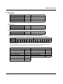
Dynamic table
For dynamic tables, there is no fixed assignment of the register areas. Depending on the structure of the Inline station, the
following general order of the process data applies:
– DATA IN (bit-oriented)
– DATA IN (byte-oriented)
– DATA OUT (bit-oriented)
– DATA OUT (byte-oriented)
Modbus register table
8000 - 8192 (16-bit word)
Internal IL MOD BK tables
Dynamic process data table
Function codes that can be used
fc2 to fc16
IL MOD BK DI8 DO4-PAC
Order-No.: 2878696
PWR
O1
I1
AO2
AO1
AI2
AI2
DI2
DI8
DO2
DO8
DI8 ETH BK
MOD BK
DO4 ETH BK
Assignment of the process data in dynamic tables
I2
D E
MODBUS RTU/ASCII
UL TR
US CO
UM WD
1
3
2
4
1
3
2
4
5 7
6 8
ADDRESS
0
2
14
12
4
10
6
9 8
x10
x1
MODBUS
X1
Modbus register/location of process data
DATA IN
DI
AI
Address 8000
Address 8001
Address 8002
Byte-oriented Address 8003
Address 8004
Address 8005
Address 8006
Address 8007
Address 8008
Bit-oriented
xxxxxxxx
xxxxxxxx
xx
Channel 1 value
Channel 2 value
Channel 1 value
Channel 2 value
Channel 1 status
Channel 2 status
DATA OUT
DO
AO
Address 8009
Address 8010
Address 8011
Byte-oriented Address 8012
Address 8013
Address 8014
Address 8015
Address 8016
Address 8017
Address 8018
xxxx
xxxxxxxx
Bit-oriented
Figure 11
7258_en_03
xx
Channel 1 parameter
Channel 2 parameter
Channel 1 parameter
Channel 2 parameter
Channel 1 value
Channel 1 value
Channel 2 value
7275C014
Example for the location of process data in dynamic tables
PHOENIX CONTACT
24
IL MOD BK DI8 DO4-PAC
14.2
Special registers
Modbus register table
1280 (16-bit word)
Access
Read/write
1400 – 1463 (16-bit word)
Read
2002 (16-bit word)
2004 (16-bit word)
2006 (16-bit word)
2100 (16-bit word)
Read/write
Read
Read/write
Write
2101 (16-bit word)
Write
2102 (16-bit word)
2103 (16-bit word)
Write
Write
2104 (16-bit word)
6020 - 6093 (16-bit word)
7996 (16-bit word)
7997 (16-bit word)
7998 (16-bit word)
7999 (16-bit word)
Write
Write
Read
Read
Read
Read
14.3
Internal IL MOD BK tables
Modbus telegram watchdog (connection monitoring),
(default = 10000 ms)
Up to 1400: Number of local bus devices
Above 1401: ID code of the relevant device
Fault response mode (default = reset fault mode)
Net Fail reason
Command register (command word)
Transmission mode: RTU, ASCII (default = 0 = RTU mode)
see table on page 13
Baud rate: 1200 ... 115200
(Default = 4 = 19200), see table on page 13
Data bits: 7, 8 (default = 1 = 8 bits), see table on page 13
Parity: None, even, odd (default = 1 = even parity),
see table on page 13
Stop bits: 1, 2 (default = 0 = 1 stop bit), see table on page 13
PCP
Status register (status word)
Local bus diagnostic status register
Local bus diagnostic parameter register 1
Local bus diagnostic parameter register 2
Description of special registers
Modbus telegram watchdog (connection monitoring),
(1280)
Special feature when disabling the watchdog via write
access to register 1280:
Valid values for the register are 0; 200 ms to 65000 ms.
Settings modified by write access (disable watchdog,
modify monitoring time) are only applied following a power
up reset. Watchdog activation via register 1280 is applied
immediately during operation.
The watchdog monitors Modbus telegrams and is triggered
each time a Modbus telegram is received correctly. It can be
enabled and disabled via the rotary encoding switches, see
"Parameterization via rotary encoding switches" on
page 12. The time can be set via register 1280 (0 = disabled;
200 ms to 65000 ms).
Actions after triggering the watchdog:
The action taken when the watchdog is triggered depends
on the set fault response mode. By default upon delivery,
the fault response mode is set to reset fault mode. For reset
fault mode, the following applies:
– Set digital outputs to zero
– Freeze analog outputs
– Watchdog LED ON
7258_en_03
PHOENIX CONTACT
25
IL MOD BK DI8 DO4-PAC
Fault response mode, (2002)
Fault response mode
Standard fault mode
Reset fault mode (default)
Hold last state mode
Value
0
1
2
Function
All outputs are set to "0".
The digital outputs are set to "0" and the analog outputs are held at the last
value.
All outputs are held at their last value.
Net Fail reason, (2004)
Status register (status word), (7996)
This register can be used to read the reason after the
Net Fail signal has been triggered. For the
IL MOD BK DI8 DO4-PAC there can only be one reason:
the connection monitoring watchdog has failed. In Net Fail
Reason register 2004, the value 000Dhex appears.
Only the two least significant bits have a function. If bit 0 =
"0", this means that an error (e.g., a bus error) has occurred.
If bit 0 = "1", no error has occurred. Bit 1 indicates whether a
Net Fail occurred (bit 1 = 1) or not
(bit 1 = 0).
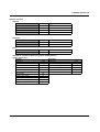
Command register (command word), (2006)
Activation/deactivation of plug and play mode is performed
in the least significant bit of the command word. Bit 0 = "0" > plug and play mode deactivated; bit 0 = "1" ->
plug and play mode activated.
If a Net Fail occurred, it can be acknowledged by setting
bit 1 in the command word. If the Net Fail has been
acknowledged successfully, bit 1 is reset to "zero".
This results in the following values for the status word:
– 0: An error occurred (e.g., bus error)
– 1: No error occurred
– 2: A Net Fail occurred
15 14 13 12 11 10 9 8 7 6
Reserved bits
Figure 13
5
4
3
2
1 0
X X
Status word
If a peripheral fault occurred, it can be acknowledged by
setting bit 2 in the command word. If the peripheral fault has
been acknowledged successfully, bit 2 is reset to 0.
15 14 13 12 11 10 9 8 7 6 5 4 3 2 1 0
Reserved bits
X X X
Clear peripheral fault
Clear Net Fail
Plug and play
Figure 12
7258_en_03
61560030
Command word
PHOENIX CONTACT
26
IL MOD BK DI8 DO4-PAC
Local bus diagnostic status register (7997)
PCP registers (6020 - 6093)
Each bit in the local bus diagnostic status register is
assigned a state of the local bus master on the bus coupler.
The states in the error bits (USER, PF, BUS, CTRL) are
described in greater detail using the diagnostic parameter
register. Whenever one of the error bits described above is
set, the diagnostic parameter register is rewritten.
Otherwise, the diagnostic parameter register has the value
0000hex.
The PCP registers are divided into two classes:
1. Communication registers for exchanging data with the
desired PCP device
2. Configuration registers for selecting the invoke ID,
index, and subindex of the PCP device
Bit Constant
0
USER_BIT
1
PF_BIT
2
3
4
Meaning
Application program error
Local bus device detected a
peripheral fault
BUS_BIT
Error on local bus
CTRL_BIT
Local bus master has an internal error
DETECT_BIT Error localization
("LOOK FOR FAIL")
RUN_BIT
Exchanging data cycles
ACTIVE_BIT Local bus master ACTIVE
READY_BIT Local bus master READY, selftest
completed
5
6
7
For additional information about PCP
communication, please refer to the
IBS SYS PCP G4 UM E user manual.
The terminal supports eight PCP devices, therefore eight
communication registers and 24 configuration registers are
supported.
Local bus diagnostic parameter register 1 (7998)
For detected local bus errors, the local bus diagnostic
parameter register contains the error location:
Error location, e.g., device number 0.3
Device number of a device, e.g., "0.3" for bus segment 0;
device 3
S e g m e n t n u m b e r
0
P o s itio n in th e s e g m e n t
0
0
7
3
n + 1
n
0
7
0
7 2 7 5 a 0 0 7
Figure 14
Contents of the local bus diagnostic parameter
register (example)
Local bus diagnostic parameter register 2 (7999)
Local bus diagnostic parameter register 2 contains
additional information about the error codes.
For additional information about local bus
diagnostics, please refer to the
IBS SYS FW G4 UM E user manual.
7258_en_03
PHOENIX CONTACT
27
IL MOD BK DI8 DO4-PAC
PCP registers
Communication
reference
CR 2
CR 3
CR 4
CR 5
CR 6
CR 7
CR 8
CR 9
7258_en_03
Example:
Communication
register
6020
Configura- Remark
tion register
6021
6022
6023
6024 - 6029
Index
Subindex
Invoke ID
Reserved
6031
6032
6033
6034 - 6039
Index
Subindex
Invoke ID
Reserved
6041
6042
6043
6044 - 6049
Index
Subindex
Invoke ID
Reserved
6051
6052
6053
6054 - 6059
Index
Subindex
Invoke ID
Reserved
6061
6062
6063
6064 - 6069
Index
Subindex
Invoke ID
Reserved
6071
6072
6073
60724 - 6079
Index
Subindex
Invoke ID
Reserved
6081
6082
6083
6084 - 6089
Index
Subindex
Invoke ID
Reserved
6091
6092
6093
6094 - 6099
Index
Subindex
Invoke ID
Reserved
6030
6040
In order to read object 5FE0hex of an IB IL RS 232 with
communication reference 4, first set the configuration
registers (6041 - 6043) to the desired values with the FC 16
command (e.g., 6041 index: 5FE0hex, 6042 subindex: 0hex,
6043 invoke ID: 0hex). The fc3 command can then be used
to read 29 words via communication register 6040.
A Modbus function is only ever used for read/write access to
a PCP index. For example, the fc3 command cannot be
used to read 20 words from registers 6020 to 6039.
The communication register contains a different value range
due to the selected values of the register and the terminal
used. Therefore, the IB IL RS 232 terminal, for example,
has three different PCP objects: two objects are one word
long, but the third is 29 words long. The three configuration
registers can be read/written with a single Modbus
command. An attempt to access a reserved register
generates an exception response.
6050
6060
6070
6080
6090
PHOENIX CONTACT GmbH & Co. KG • 32823 Blomberg • Germany • Phone: +49-(0) 5235-3-00
PHOENIX CONTACT • P.O.Box 4100 • Harrisburg • PA 17111-0100 • USA • Phone: +717-944-1300
www.phoenixcontact.com
28