1
IL ETH BK DI8 DO4 2TX-PAC
4 2T
DO
DI8 1
H BK 0398
IL ET-No.: 2700 .xx
/1 xx
er
Ord W: 00xx.xx.
/F
HW Addr.: ET
MAC
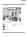
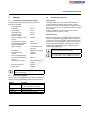
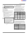
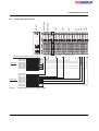
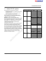
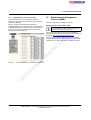
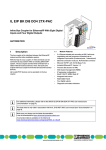
Inline bus coupler for Ethernet with eight digital
inputs and four digital outputs
E
E
TH
X-PA
I2
C
RN
I1
O1
PWR
RY
BO
PP
UL
NF
US
CO
UM
D
E
2
1
4
3
2
1
4
3
7
5
8
6
T
SE
RE
T1
AC
K1
LN
X1
AUTOMATION
T2
AC
K2
LN
co
© PHOENIX CONTACT - 05/2008
Description
–
–
–
–
ne
With the help of the bus coupler, 61 Inline devices can be
connected at any position within an existing Ethernet
system. The bus coupler and the Inline devices form one
station with a maximum of 63 local bus devices. Here, the
inputs and outputs of the bus coupler together form the first
and second local bus devices.
Process data access via XML
Ethernet TCP/IP
– Management via SNMP
– Integrated web server
IP address setting via BootP (can be switched off)
Automatic baud rate detection on the local bus
(500 kbps or 2 Mbps)
Diagnostic and status LEDs
Eight digital inputs
Four digital outputs
Approved for use in zone 2 potentially explosive areas
(observe the notes on page 11)
s.
The bus coupler is the interface between the Ethernet
network and the Inline installation system.
nt
1
m
X2
Data Sheet
7275_en_03
po
Up to 16 PCP devices can be operated on the bus coupler.
in
ec
–
–
–
–
2 x Ethernet twisted pair according to 802.3 with auto
negotiation and auto crossover connected via an
integrated 3-port switch (2 external ports, 1 internal
port)
Transmission speeds of 10 Mbps and 100 Mbps
Ethernet connection via 8-pos. RJ45 female connector
Electrical isolation of Ethernet interface and logic
Software interface: Modbus/TCP, Modbus/UDP or DDI
(Device Driver Interface)
on
l
–
om
Features
–
–
–
–
This data sheet is only valid in association with the IL SYS INST UM E user manual.
Make sure you always use the latest documentation.
It can be downloaded at www.download.phoenixcontact.com.
A conversion table is available on the Internet at www.download.phoenixcontact.com/general/7000_en_00.pdf.
IL ETH BK DI8 DO4 2TX-PAC
Table of contents
Description.................................................................................................................................. 1
2
Ordering data.............................................................................................................................. 3
3
Technical data ............................................................................................................................ 4
4
Circuit diagram............................................................................................................................ 7
5
Local diagnostic and status indicators ........................................................................................ 8
6
Reset button ............................................................................................................................... 9
7
Connecting the supply, actuators, and sensors .......................................................................... 9
8
Notes on using the terminal in potentially explosive areas .........................................................11
9
Startup .......................................................................................................................................12
co
m
1
s.
10 Web-Based Management (WBM)..............................................................................................13
nt
11 Startup behavior of the bus coupler ...........................................................................................18
ne
12 Monitoring functions ..................................................................................................................20
13 Modbus protocol........................................................................................................................23
po
14 Modbus/TCP PCP registers.......................................................................................................28
15 Device Driver Interface (DDI) .....................................................................................................29
om
16 Firmware services......................................................................................................................31
17 PCP communication ..................................................................................................................32
on
l
in
ec
18 Simple Network Management Protocol - SNMP ........................................................................33
7275_en_03
PHOENIX CONTACT
2
IL ETH BK DI8 DO4 2TX-PAC
2
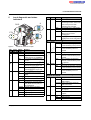
Ordering data
Product
Description
Order No.
Pcs./Pkt.
IL ETH BK DI8 DO4 2TX-PAC
2703981
1
Accessories: Ethernet
Description
Type
Order No.
Pcs./Pkt.
Gray RJ45 connector set for linear cable
FL PLUG RJ45 GR/2
2744856
2
Green RJ45 connector set for crossed cable
FL PLUG RJ45 GN/2
2744571
2
FL CAT5 HEAVY
FL CAT5 FLEX
2744814
1
2744830
1
Assembly tool for RJ45 connector
FL CRIMPTOOL
2744869
1
Type
Order No.
Pcs./Pkt.
IL BKDIO-PLSET
2878599
1
s.
Accessories: Additional system components
Description
co
Double sheathed Ethernet cable
Flexible Ethernet cable
m
Type
Inline bus coupler for Ethernet
with 8 digital inputs and 4 digital outputs,
including accessories (Inline connector, labeling fields and end plate)
FO interface converters for data conversion and data transmission using fiber optics (see INTERFACE catalog)
po
Connector set for Inline bus coupler with connected I/Os
ne
Accessories: Connector as replacement item
Description
nt
Power supply units for supplying the bus coupler (see INTERFACE catalog)
Accessories: Other
Description
Order No.
Pcs./Pkt.
CLIPFIX 35-5
3022276
50
End clamp for securing the module/the Inline station on the DIN rail for a
vertical mounting position; above and below the module/Inline station
E/AL-NS 35
1201662
10
IL CP
2742683
100
1
1
in
ec
om
Type
Quick mounting end clamp for securing the module/the Inline station on the
DIN rail for a horizontal mounting position; to the right and left of the module/
Inline station
Keying profile
ZB 6 ... see CLIPLINE catalog
ZB 12 ... see CLIPLINE catalog
DIN EN 50022 DIN rail, 2 meters
NS 35/7,5 PERF
NS 35/7,5 UNPERF
0801733
0801681
Documentation
Description
Type
Order No.
Pcs./Pkt.
"Automation Terminals of the Inline Product Range" user manual
IL SYS INST UM E
2698737
1
"I/O Terminals at Bus Couplers" application note
AH IL BK IO LIST
9015358
1
"Inline Terminals for Use in Zone 2 Potentially Explosive Areas"
application note
AH EN IL EX ZONE 2
–
"Driver Reference Manual for G4-Based Controller Boards Using PC Bus and
Ethernet" user manual
IBS PC SC SWD UM E
2745172
on
l
Zack marker strip to label the terminals
1
"Firmware Services and Error Messages" user manual
IBS SYS FW G4 UM E
2745185
1
"Peripherals Communication Protocol (PCP)" user manual
IBS SYS PCP G4 UM E
2745169
1
7275_en_03
PHOENIX CONTACT
3
IL ETH BK DI8 DO4 2TX-PAC
3
Technical data
General data
Housing dimensions (width x height x depth)
80 mm x 121 mm x 70 mm
Weight
260 g (with connectors)
Ambient temperatures (operation)
-25°C to +55°C
Ambient temperature (storage)
-25°C to +85°C
Humidity (operation/storage/transport)
10% to 95% according to EN 61131-2
Air pressure (operation/storage/transport)
70 kPa to 106 kPa (up to 3000 m above sea level)
Degree of protection
IP20 according to IEC 60529
Class of protection
Class 3 according to EN 61131-2, IEC 61131-2
Connection data for Inline connectors
Spring-cage terminals
Conductor cross-section
0.2 mm2 to 1.5 mm2 (solid or stranded), 24 - 16 AWG
co
m
Connection type
System data
63, maximum (including two devices on the bus coupler)
Maximum number of I/O data
512 bytes
s.
Number of devices per station
500 kbps or 2 Mbps (automatic detection)
Maximum power supply at UL (7.5 V)
0.8 A, maximum
Maximum power supply at UANA
0.5 A, maximum
Maximum power supply at US
8 A, maximum
Maximum power supply at UM
8 A, maximum
ne
nt
Transmission speed on the local bus
Interfaces
po
Ethernet interface
Number
Two
10Base-T and 100Base-TX with auto negotiation and auto crossover
8-pos. RJ45 female connector on the bus coupler
om
Connection format
Transmission speed
Connection method
in
ec
Inline local bus
Connection
10 Mbps (10Base-T), 100 Mbps (100Base-TX)
Half duplex, full duplex (automatic detection)
Twisted pair cable, CAT 5, RJ45 female connector
Data routing
61, maximum
– Limitation through power supply unit
Maximum logic current consumption of the connected local bus modules:
Imax ≤ 0.8 A DC
on
l
– Limitation through software
Observe the logic current consumption of each device when configuring an Inline station. This information is given in every module-specific
data sheet. The current consumption can differ depending on the individual module. The permissible number of devices that can be
connected therefore depends on the specific station structure.
Supply voltage for UBK, US, and UM
Recommended cable lengths
30 m, maximum; routing cables through outdoor areas is not admissible
Continuation
Via potential routing
Nominal value
24 V DC
Permissible range (according to EN 61131-2)
19.2 V to 30 V (ripple included)
NOTE: Module damage due to overload
This 24 V area must be externally protected. The power supply unit must be able to supply 4 times the nominal current of the external fuse,
to ensure that it trips in the event of an error.
The bus coupler supply UBK (24 V) generates the communications power UL (7.5 V) and the analog supply UANA (24 V).
7275_en_03
PHOENIX CONTACT
4
IL ETH BK DI8 DO4 2TX-PAC
Current consumption/power consumption
Current consumption from UBK (24 V)
Current consumption of module electronics
0.08 A, maximum
Current consumption of local bus (800 mA load at 7.5 V)
0.4 A, maximum
Current consumption from UANA (24 V)
0.5 A, maximum
0.98 A, maximum
Total current consumption from UBK
Current consumption from US (24 V)
3 mA +4 mA for each output set + load, typical; 8 A, maximum
Current consumption from UM (24 V)
3 mA 3 mA for each output set + load, typical; 8 A, maximum
Power dissipation of entire device
3 W, typical
4
Connection method for actuators
2 and 3-wire technology
Nominal output voltage UOUT
24 V DC
Differential voltage for Inom
<1V
0.5 A
Total current
2A
s.
Nominal current Inom per channel
co
Number
Nominal load
12 W
nt
Ohmic
Lamp
12 W
Inductive
12 VA (1.2 H)
0.5 Hz (1.2 H), maximum
ne
Switching frequency with nominal inductive load
m
Digital outputs
Overload response
Auto restart
Response with inductive overload
Output may be damaged
Protected against reverse voltages
Resistance to permanently applied reverse voltages
Response upon power down
po
Reverse voltage protection against short pulses
Protected against reverse voltages, permissible current 2 A, maximum
The output follows the supply voltage without delay.
Maximum output current when switched off
om
Limitation of the voltage induced on circuit interruption
Overcurrent shutdown
-30 V, approximately
0.7 A, minimum
10 µA
Digital inputs
Number
in
ec
When not loaded, a voltage can be measured even at an output that is not set.
8
2 and 3-wire technology
Input design
According to EN 61131-2 Type 1
on
l
Connection method for sensors
Definition of switching thresholds
Maximum low-level voltage
ULmax < 5 V
Minimum high-level voltage
UHmin > 15 V
Common potentials
Sensor supply UM, ground
Nominal input voltage UIN
24 V DC
Permissible range
-30 V < UIN < +30 V DC
Nominal input current for UIN
3 mA, typical
Current flow
Limited to 3 mA, maximum
Delay time
< 500 ms
Permissible cable length to the sensor
100 m
Use of AC sensors
AC sensors in the voltage range < UIN are limited in application
7275_en_03
PHOENIX CONTACT
5
IL ETH BK DI8 DO4 2TX-PAC
Safety equipment
Supply voltage
Surge voltage
Yes, suppressor diode 35 V
Polarity reversal
Yes, suppressor diode 35 V
Digital outputs
Short circuit
Yes, integrated free running circuit in the output chip
Overload
Yes, integrated free running circuit in the output chip
Digital inputs
Polarity reversal
Yes, diode connected in series as protection against polarity reversal
Yes
Actuator supply not present
Yes
Short circuit/overload of an output
Yes
co
Sensor supply not present
m
Error message sent to the higher-level control system
Mechanical requirements
5g load, 2 hours in each direction
Shock test according to IEC 60068-2-27; EN 60068-2-27
25g load for 11 ms, half sinusoidal wave,
three shocks in each direction and orientation
nt
ne
Conformance with EMC Directive 2004/108/EC
Noise immunity test according to EN 61000-6-2
s.
Vibration test; sinusoidal vibrations according to IEC 60068-2-6;
EN 60068-2-6
EN 61000-4-2/
IEC 61000-4-2
Electromagnetic fields
EN 61000-4-3
IEC 61000-4-3
Criterion A
Field strength: 10 V/m
Fast transients (burst)
EN 61000-4-4/
IEC 61000-4-4
Criterion A
All interfaces: 1 kV
om
po
Electrostatic discharge (ESD)
Conducted interference
in
ec
Surge voltage
Criterion B
6 kV contact discharge
8 kV air discharge
Criterion B
All interfaces: 2 kV
EN 61000-4-5/
IEC 61000-4-5
Criterion B
DC supply cables:
0.5 kV / 1 kV (symmetrical/asymmetrical)
Fieldbus cable shield 1 kV
EN 61000-4-6
IEC 61000-4-6
Criterion A
Test voltage 10 V
Noise emission test according to EN 61000-6-4
Approvals
on
l
Noise emission of housing
EN 55011
Class A
For the latest approvals, please visit www.download.phoenixcontact.com or www.eshop.phoenixcontact.com.
7275_en_03
PHOENIX CONTACT
6
IL ETH BK DI8 DO4 2TX-PAC
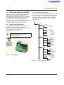
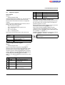
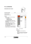
4
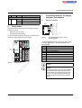
Circuit diagram
IB
µP
Local bus
DO1...4
7,5V
nt
8 x DI
24V
24V
4x
DO
US
µ P
IB
U L-
C
US
UM
7410A005
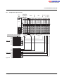
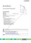
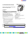
Circuit diagram of the Ethernet bus coupler
on
l
Key:
in
ec
PWR
om
UL
2 TX ETH
Figure 1
po
UM
A
UANA
ne
24V
U L+
s.
co
DI1...8
m
B
Microprocessor
The gray areas in the basic circuit diagram represent the electrically
isolated areas:
Protocol chip
A: Ethernet interface
B: Logic
C: I/O devices
Optocoupler
Ethernet switch
PNP transistor
Transmitter with electrical isolation
7275_en_03
PHOENIX CONTACT
7
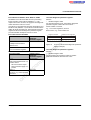
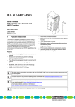
IL ETH BK DI8 DO4 2TX-PAC
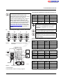
Local diagnostic and status
indicators
I2
PWR
BF
I2
PWR
BO
UL
US
UM
RY
PP
NF
CO PAC
DIA
X4 2T
DO
DI8 1
H BK 0398
IL ET-No.: 2700 .xx
/1 xx
er
Ord W: 00xx.xx.
/F
HW Addr.: ET
MAC RN
ETH
H
ET
LNK1
BF
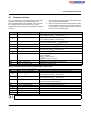
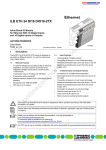
LED Color Status
NF
Red
ON
E
ACT1
OFF
5 6
7 8
CO
Red
I2
I1
O1
PWR
RY
PP
UL
NF
US
CO
UM
BO
D
E
2
1
4
3
2
1
4
3
I1
7
5
8
6
ON
I1
DIA
ACT2
RE
SE
A
LN
1 2
3 4
T
1
CT
O1
D E
K1
X1
AC
LN
T2
K2
1 2
3 4
X2
OFF
PWR: Power
UL
Green
O1
co
LNK2
Meaning
Network Failure
A network error occurred. The
monitoring function detected an
error or the process data
watchdog was activated.
No network error, normal state
COnfiguration
The active station configuration
differs from the saved
configuration
The active station configuration
matches the saved configuration
m
5
ULogic
24 V bus coupler supply / internal
communications power present
OFF
24 V bus coupler supply / internal
communications power not
present
US
Green
USegment
ON
24 V segment circuit supply /
internal communications power
present
OFF
24 V segment circuit supply /
internal communications power
not present
UM Green
UMain
ON
24 V main circuit supply / internal
communications power present
OFF
24 V I/O supply / internal
communications power not
present
O1: Diagnostics of the Inline station/diagnostics and
status of the outputs
D
Green
Diagnostics
ON
Data transmission within the
station active
Flashing Data transmission within the
station not active
E
Red
Error
ON
Short circuit/overload at one of
the outputs
OFF
No short circuit/overload of
outputs
1-4 Yellow
O1...O4
ON
Output active
OFF
Output not active
LED Color Status
ETH/PWR: Ethernet
LNK Green
1/2
ON
nt
Indicators on the bus coupler
Meaning
on
l
in
ec
om
po
Link of port 1/2
Connection via Ethernet to a
module via port 1/2 established.
OFF
No connection established via
port 1/2
ACT Yellow
Activity on port 1
1/2
ON
Transmission or reception of
Ethernet telegrams at port 1/2
OFF
No transmission or reception of
Ethernet telegrams at port 1/2
BO Green
Bootloader (Boot)
ON
Boot loader active, firmware
started
Flashing Waiting for BootP reply
OFF
Firmware started successfully
RY
Green
Ready
ON
Connection to a process data
client (Modbus/TCP (UDP) or
DDI) established
Flashing Firmware ready to operate
OFF
Firmware not active
PP
Yellow
Plug and Play
ON
Plug and play mode active
OFF
Plug and play mode not active
ne
Figure 2
s.
ON
7275_en_03
PHOENIX CONTACT
8
IL ETH BK DI8 DO4 2TX-PAC
LED Color Status Meaning
I1: Status of the inputs
1-8 Yellow
I1 ... I8
ON
Input active
OFF
Input not active
7
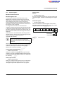
Connecting Ethernet, the supply,
actuators, and sensors
7.1
Ethernet connection
R J 4 5
6
Reset button
P in 1
T D +
P in 2
T D -
P in 3
R D +
The reset button is located on the front of the bus coupler.
P in 4
re s .
It has two functions:
– Restarting the bus coupler
– Restoring the default settings
P in 5
re s .
P in 7
RESET
O1
I1
BO RY
D E
UL PP
US NF
UM CO
1
3
2
4
1
3
2
4
5 7
6 8
po
RESET
LNK1
ACT1
om
X1
LNK2
ACT2
X2
co
Pin assignment of the 8-pos. RJ45
female connector
Connect Ethernet to the bus coupler via an 8-pos. RJ45
connector. Please refer to the pin assignment in the
following table:
I2
Pin
1
2
3
4
5
6
7
8
ne
ETHERNET
PWR
Figure 4
re s .
nt
IL ETH BK DI8 DO4 2TX-PAC
Order-No.: 2703981
HW/FW: 00/100
MAC Addr.: xx.xx.xx.xx
P in 8
re s .
s.
To restore the default settings (see page 12), hold down the
reset button when applying the power supply.
R D -
m
P in 6
Assignment
TxD + (transmit data +)
TxD - (transmit data -)
RxD + (receive data +)
Reserved
Reserved
RxD - (receive data -)
Reserved
Reserved
Reset button
on
l
Figure 3
in
ec
7275A006
7275_en_03
Both Ethernet interfaces have an auto crossover
function.
Shield
The shielding ground of the connected twisted
pair cables is electrically connected with the
socket. When connecting network segments,
avoid ground loops, potential transfers, and
voltage equalization currents via the braided
shield.
PHOENIX CONTACT
9
IL ETH BK DI8 DO4 2TX-PAC
Terminal point assignment of the power connector (1)
Observe the bending radii
Terminal
points
1.1
1.2
1.3
1.4
The housing dimensions specified under
"General data" on page 4 refer to the bus coupler
with Inline connectors without Ethernet
connection. When installing the bus coupler in a
control box observe the bending radii of the
Ethernet cables and the connectors used (e.g.,
FL CAT5 FLEX: 30 mm for permanent installation
and FL CAT5 HEAVY: 30 mm without outer
sheath and 45 mm with outer sheath; see also
www.interbusclub.com/itc/eth/). To keep these
bending radii use angled RJ45 connectors, if
required.
I2
1.1 2.1
3.1 4.1
2
1.2 2.2
2
1.3 2.3
1.3
3
3
1.4 2.4
1.4
4
4
2.1
1.1
1
2.2
1.2
2
2.3
2.4
1.3
1.4
1
Figure 5
UBK-
1
2
2.2
1.2
2
1.3 2.3
2.3
3
3
1.4 2.4
2.4
4
4
1.3
1.4
1
2.1
3.1
1
2
2.2
3.2
2
1.2 2.2
1.3 2.3
3
3
1.4 2.4
4
4
2.3
2.4
3.3
3.4
3
1
4.1
2
4.2
3.2 4.2
3.3 4.3
4.3
3
3
3.4 4.4
4.4
4
4
4
co
m
7275B003
Terminal point assignment of the Inline
connectors
PWR DO4 DI4 DI4
2
1
3
4
on
l
+
1.1
1.2 2.2
+
-
2.1
2
J
US
1
po
1.2
1
om
1
in
ec
1.1
For information on the power supplies, please
refer to the IL SYS INST UM E user manual.
s.
I1
1.1 2.1
UM
UM
GND UM, US
Functional earth
ground (FE)
Terminal points 1.3 and 2.3 on the connector can
be jumpered if the same reference potential is to
be used for the communications power and the
segment voltage.
nt
O1
1.1 2.1
Assignment
The module is designed exclusively for SELV
operation according to IEC 950 / EN 60950 /
VDE 0805.
Connecting the supply, actuators, and sensors
PWR
Terminal
points
2.1
US
UBK
2.2
GND UBK
2.3
Functional earth 2.4
ground (FE)
NOTE: Malfunction
ne
7.2
Assignment
Terminal point assignment of the output connector (2)
Terminal
points
1.1
1.2
1.3
1.4
Assignment
OUT1
GND
FE
OUT3
Terminal
points
2.1
2.2
2.3
2.4
Assignment
OUT2
GND
FE
OUT4
Terminal point assignment of the input connector (3)
IN6
+24 V
+24 V
IN8
Terminal
points
1.1
1.2
1.3
1.4
Assignment
IN1
UM
GND
IN3
Terminal
points
2.1
2.2
2.3
2.4
Assignment
IN2
UM
GND
IN4
UM
Figure 6
OUT2
-
+
Ethernet
OUT3
Terminal point assignment of the input connector (4)
Connection example
J: Internal jumper
7275B004
Terminal
points
3.1
3.2
3.3
3.4
Assignment
IN5
UM
GND
IN7
Terminal
points
4.1
4.2
4.3
4.4
Assignment
IN6
UM
GND
IN8
Connect the bus coupler according to Figure 6.
7275_en_03
PHOENIX CONTACT
10
IL ETH BK DI8 DO4 2TX-PAC
8
Notes on using the terminal in potentially explosive areas
Approval according to EC Directive 94/9 (ATEX)
II 3G Ex nAC IIC T4 X
WARNING: Explosion hazard
Before using an Inline terminal in a zone 2
potentially explosive area, check that the
terminal has been approved for installation in
this area.
4.
5.
ne
nt
For a list of terminals approved for use in zone 2
potentially explosive areas, please refer to the
AH EN IL EX ZONE 2 application note.
6.
po
7.
II 3G Ex nAC IIC T4 X
Potential routing 4 A maximum
for use in Ex areas
INTERBUS
UL
xx
LISTED
31ZN
Proc. Ctrl. Eqpt. For Haz. Locs.
Cl. I, Zn. 2, AEx nC IIC T5
Cl. I, Zn. 2, Ex nC IIC T5
Cl. I, Div. 2, Grp. A,B,C,D T5
5561C001
Typical labeling of terminals for use in
potentially explosive areas
on
l
in
ec
Figure 7
GL
om
IBx IL xx xx x
Order-No.: xxxxxxx
Module-ID: xx HW/FW XX/-
m
3.
When working on the Inline terminal, always disconnect
the supply voltage.
The Inline terminal may only be installed, started up,
and maintained by qualified specialist personnel.
Install the Inline terminals in a control cabinet or metal
housing. The minimum requirement for both items is
IP54 protection according to EN 60529.
The Inline terminal must not be subject to mechanical
strain and thermal loads, which exceed the limits
specified in the product documentation.
The Inline terminal must not be repaired by the user.
Repairs may only be carried out by the manufacturer.
The Inline terminal is to be replaced by an approved
terminal of the same type.
Only category 3G equipment may be connected to
Inline terminals in zone 2.
Observe all applicable standards and national safety
and accident prevention regulations for installing and
operating equipment.
co
1.
2.
WARNING: Explosion hazard
Only Inline terminals that are approved for
use in potentially explosive areas may be
snapped next to this Inline terminal.
Check the labeling on the Inline terminal and
the packaging (see Figure 7).
Before startup, ensure that the following
points and instructions are observed.
s.
This Inline terminal conforms to the requirements of
protection type "n" and can be installed in a zone 2
potentially explosive area. This Inline terminal is a category
3G item of electrical equipment.
Restrictions
WARNING: Explosion hazard
When using terminals in potentially explosive
areas, observe the technical data and limit
values specified in the corresponding
documentation (user manual, data sheet,
package slip).
WARNING: Explosion hazard
Restrictions regarding the Inline system
Please make sure that the maximum
permissible current of 4 A flowing through
potential jumpers UM and US (total current) is
not exceeded when using the Inline terminals in
potentially explosive areas.
The supply of UM and US at the bus coupler
must not exceed 4 A.
7275_en_03
PHOENIX CONTACT
11
IL ETH BK DI8 DO4 2TX-PAC
9
Startup
9.3
9.1
Default upon delivery/default settings
Initial startup:
During initial startup, the bus coupler transmits BootP
requests without interruption until it receives a valid IP
address. The requests are transmitted at varying intervals
(2 s, 4 s, 8 s, 2 s, 4 s, etc.) so that the network is not loaded
unnecessarily.
If valid IP parameters are received, they are saved as
configuration data by the bus coupler.
By default upon delivery, the following functions and
features are available:
–
Plug and Play Mode
Expert Mode
m
If the bus coupler already has valid configuration data and
BootP is not disabled, it only transmits three more BootP
requests on a restart. If it receives a BootP reply, the new
parameters are saved. If the bus coupler does not receive a
reply, it starts with the previous configuration. If BootP is
disabled and a valid configuration is available, the bus
coupler starts immediately.
co
Disable
500 ms
nt
IL ETH BK DI8 DO4
2TX-PAC
Ethernet bus terminal
Unknown
Unknown
s.
0.0.0.0
c2703981.fw
For the definition of the IP address via BootP, you
can use any BootP server available.
ne
–
Description:
Physical Location:
Contact:
Process Data Monitoring
Process Data Watchdog
Timeout:
Fault Response Mode:
Further restarts:
To check whether BootP is disabled, refer to the
"IP Configuration" menu in WBM, see page 14.
po
–
0.0.0.0
0.0.0.0
0.0.0.0
Enable
Reset Fault Mode
(Default)
Enable
Disable
om
–
IP Configuration
IP Address
Subnet Mask:
Default Gateway:
BootP Requests:
Software Update
Software Update on Next
Reboot:
TFTP Server IP Address:
Downloadable File Name:
System Identification
Name of Device:
in
ec
–
Sending BootP requests
By default upon delivery, the bus coupler has no
valid IP parameters.
Starting the firmware
on
l
9.2
Once you have connected the power to the bus coupler, the
firmware is started. The following LED sequence is shown:
Display
BO flashing
BO ON
BO OFF
RY flashing
7275_en_03
Meaning
Bootloader is started
BootP requests are transmitted
Extracting firmware
Firmware started
Firmware ready to operate
PHOENIX CONTACT
12
IL ETH BK DI8 DO4 2TX-PAC
10
10.2
Web-Based Management (WBM)
The bus coupler has a web server, which generates the
required pages for web-based management and,
depending on the requirements of the user, sends them to
the Factory Manager or a standard web browser. Webbased management can be used to access static
information (e.g., technical data, MAC address) or dynamic
information (e.g., IP address, status information) or to
change the configuration (password-protected).
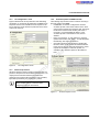
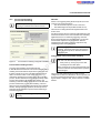
Structure of the web pages
The web pages for the Ethernet bus coupler are divided into
two sections. The left-hand side has the selection menu with
the relevant submenus. The right-hand side displays the
information related to the menu item. Static and dynamic
information about the bus coupler can be found in the
following menus.
< ip - a d d r e s s >
in d e x .h tm
10.1
Calling Web-Based Management
G e n e ra l
In s tr u c io n s
m
The IL ETH BK DI8 DO4 2TX-PAC web server can be
addressed using the IP address if configured
correspondingly. The bus coupler homepage is accessed
by entering the URL "http://IP address".
In fo r m a tio n
g e n in s t.h tm
co
D e v ic e
In fo r m a tio n
s.
Example: http://172.16.113.38
G e n e ra l d e v in fo .h tm
T e c h n ic a l D a ta te c h d a ta .h tm
H a r d w a r e In s ta lla tio n
h w in s ta l.h tm
L o c a l D ia g n o s tic s
lo c d ia g .h tm
-
-
D e v ic e
C o n fig u r a tio n
IP C o n fig u r a tio n
ip c o n fig .h tm
-
ip c o n in f.h tm
S y s te m
po
ne
nt
If you cannot access the WBM pages, check the
connection settings in your browser and
deactivate the proxy, if set.
Id e n tific a tio n
s y s c o n f.h tm
-
s y s in fo .h tm
S o ftw a re U p d a te
s w u p d a te .h tm
-
s w u p in fo .h tm
om
ftp in fo .h tm
C h a n g e P a s s w o rd
p a s s w o rd .h tm
-
p a s s in fo .h tm
In lin e
S ta tio n
in
ec
S e r v ic e s s e r v ic e s .h tm
s v p p in fo .h tm
s v p fin fo .h tm
P r o c e s s D a ta M o n ito r in g
p d m o n it.h tm
-
p d m o n in f.h tm
p d n fin fo .h tm
R e m o te D ia g n o s tic s
r e m d ia g .h tm
on
l
Figure 8
-
WBM homepage
B u s C o n fig u r a tio n
b u s c o n f.h tm
P C P C o n fig u r a tio n
p c p c o n f.h tm
-
p c p in fo .h tm
Figure 9
7275_en_03
Structure of the web pages
PHOENIX CONTACT
13
IL ETH BK DI8 DO4 2TX-PAC
10.3
"IP Configuration" menu
10.5
The following steps must be carried out when executing a
firmware update using WBM:
– In WBM click on "Device Configuration" and then
"Software Update". Enter the IP address of the TFTP
server in the "TFTP Server IP Address" field. Then enter
the file name of the firmware and the path name, if
necessary, in "Downloadable File Name". In the
"Software Update on Next Reboot" field, click on
"Enable".
– Enter your password. To wait until later to apply the
update with a restart, click "Apply". To start the update
immediately, click "Apply and Reboot".
– Check the execution of the update by checking the
firmware version under "Device Information/General".
In the event of an error during the download, a restart
repeats the download. To abort the update, set
"Disable" in the "Software Update on Next Reboot"
field.
10.4
"IP Configuration" menu
Password protection
om
Figure 10
po
ne
nt
s.
co
m
Figure 9 illustrates the set IP parameters and addressing
mechanism. To change the IP parameters via WBM, BootP
Requests must be set to Disable or BootP requests to the
bus coupler must not be answered (no BootP server can be
active in the network).
Firmware update via WBM and TFTP
in
ec
All status changes to the bus coupler require the entry of a
password. The password can be changed at any time. Your
unique password must be between four and twelve
characters long (note that the password is case-sensitive).
By default upon delivery, the password is "private".
on
l
If you forget the password, the only way to access
the bus coupler again is to reset the entire
configuration using the reset button.
Figure 11
7275_en_03
"Software Update" menu
PHOENIX CONTACT
14
IL ETH BK DI8 DO4 2TX-PAC
MODULE_NUMBER
Contains the number of connected Inline terminals,
including local I/Os. In the event of a bus error, the number
of the last known operable configuration is indicated.
If BootP is set to "Enable" and a reply with values
for "TFTP Server IP Address" and "Downloadable
File Name" is received, the entries done in WMB
are overwritten with these specifications. After
restart the values accepted are displayed in
WBM.
DIAGNOSTIC_STATUS_REGISTER
Contains the INTERBUS status, represented by all bits of
the diagnostic status register. A detailed description can be
found in the diagnostic parameter register. Whenever an
error bit is set, the diagnostic parameter register is rewritten.
In the event of an error during Flash programming
(e.g., voltage interrupt), the bus coupler can only
be restarted by repeating the update. The bus
coupler starts the update automatically after a
restart. Access to WBM is no longer possible.
m
IL_BUS
Process data access via XML
IL_MODULE
The integrated web server of the IL ETH BK DI8 DO4 2TXPAC offers the option of accessing the process data of the
connected Inline terminals via a web page in XML format.
MODULE_TYPE
Contains the terminal type. Possible types are DI, DO, DIO,
AI, AO, AIO, and PCP.
ne
You can access the web pages via a standard web browser.
For calling the XML pages with the process data enter the
address in the following format in the address line of the
browser:
s.
Frame for the data of an individual Inline terminal. The
terminals are numbered consecutively from one to a
maximum of 63.
nt
10.6
co
Frame for the connected Inline terminals.
http://<IP address>/procdata.xml
XML file structure
om
The XML file contains different data areas:
po
PD_CHANNELS
10.7
IL_STATION
IL_BUS_TERMINAL
in
ec
Frame for the entire XML file. The mandatory elements of
this frame are IL_BUS_TERMINAL and IL_BUS.
on
l
This data area contains information on the entire Inline
station (bus coupler and all connected terminals). This data
area includes: TERMINAL_TYPE, the module name NAME,
the IP address IP_ADDRESS, the number of connected
terminals MODULE_NUMBER, the local bus diagnostic
status register DIAGNOSTIC_STATUS_REGISTER, and
the local bus diagnostic parameter register
DIAGNOSTIC_PARAMETER_REGISTER.
TERMINAL_TYPE
This area contains the name of the bus coupler, which is
always IL ETH BK DI8 DO4.
Number of process data channels in an Inline terminal. For
digital terminals the number of channels is equal to the
number of supported bits. For other terminals, the number of
process data words is indicated. Example: An IB IL AO 2
has two process data channels and an IB IL 24 DO 8 has
eight bits and eight process data channels.
PD_WORDS
Number of process data words in an Inline terminal. Please
note that analog terminals always have the same number of
output and input words. An IB IL AO 2 therefore also has
two input channels and an IB IL AI 2 also has two output
channels.
PD_IN
This area is used by all terminals that occupy input data. The
number of process data words depends on the terminal
type.
Examples:
a) Inline terminal with two active inputs
NAME
Contains the user-specific station name. The station name
can be modified via WBM.
IP_ADDRESS
Contains the IP address of the station.
7275_en_03
<IL_MODULE number="1">
<MODULE_TYPE>DI</MODULE_TYPE>
<PD_CHANNELS>2</PD_CHANNELS>
<PD_WORDS>1</PD_WORDS>
<PD_IN word="1">3</PD_IN>
</IL_MODULE>
PHOENIX CONTACT
15
IL ETH BK DI8 DO4 2TX-PAC
b) Inline terminal with two digital inputs and only the second
input is active.
<IL_MODULE number="3">
<MODULE_TYPE>DI</MODULE_TYPE>
<PD_CHANNELS>2</PD_CHANNELS>
<PD_WORDS>1</PD_WORDS>
<PD_IN word="1">2</PD_IN>
</IL_MODULE>
PD_OUT
This area is used by all terminals with output data. The use
of bits is identical with that in PD_IN.
In the event of an error in the Inline station, this is indicated
in the diagnostic registers. The D LED flashes on the bus
coupler. The process data is invalid because only internal
values are indicated, not the values on the local bus.
c) Inline terminal with 16 digital inputs and the 13th and the
14th inputs are active.
m
<IL_MODULE number="7">
<MODULE_TYPE>DI</MODULE_TYPE>
<PD_CHANNELS>16</PD_CHANNELS>
<PD_WORDS>1</PD_WORDS>
<PD_IN word="1">12288</PD_IN>
</IL_MODULE>
In order to make sure that only valid data is displayed, the
diagnostic register must also always be requested. The
same is true in the event of a faulty configuration. In this
case, the local bus does not run and only internal values can
be read in the XML file.
s.
co
In the event of a peripheral fault, all data is valid, except for
the data of the faulty terminal.
nt
The input word returns the value 12288 (212 + 213).
po
on
l
in
ec
om
<IL_MODULE number="10">
<MODULE_TYPE>AI</MODULE_TYPE>
<PD_CHANNELS>2</PD_CHANNELS>
<PD_WORDS>2</PD_WORDS>
<PD_IN word="1">14970</PD_IN>
<PD_IN word="2">8</PD_IN>
<PD_OUT word="1">0</PD_OUT>
<PD_OUT word="2">0</PD_OUT>
</IL_MODULE>
ne
d) Inline terminal with two analog inputs, only the first
channel being active (14970).
7275_en_03
PHOENIX CONTACT
16
on
l
in
ec
om
po
ne
nt
s.
co
m
IL ETH BK DI8 DO4 2TX-PAC
Figure 12
7275_en_03
Screen for XML data
PHOENIX CONTACT
17
IL ETH BK DI8 DO4 2TX-PAC
11
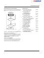
Startup behavior of the bus coupler
11.2
Expert mode
The startup behavior of the bus coupler is specified via two
system parameters, plug and play mode (Var ID 2240hex)
and expert mode (Var ID 2275hex). By default upon delivery,
plug and play mode is activated and expert mode is
deactivated.
Expert mode inactive
11.1
If expert mode is active, the bus is not started automatically.
The user must set the station to the RUN state using the
appropriate firmware commands such as
CREATE_CONFIGURATION, 0710hex and
START_DATA_TRANSFER, 0701hex. The PP and CO
LEDs are not used.
m
ne
The IL ETH BK DI8 DO4 2TX-PAC supports plug and play
mode (P&P). This mode enables Inline terminals connected
in the field to be started up using the bus coupler without a
higher-level computer. The P&P mode status (active or
inactive) is stored retentively on the bus coupler. The
current mode is displayed via the PP LED. In P&P mode, the
connected Inline terminals are detected and their function
checked. If this physical configuration is ready to operate, it
is started, however writing outputs is not enabled.
co
Plug and play mode active
s.
Please note that the following description is valid
when expert mode is deactivated.
Expert mode active
nt
Plug and play mode
If expert mode is deactivated (default upon delivery), the
bus coupler runs as described in 11.1.
po
To enable writing outputs, P&P mode must be deactivated.
The deactivation of P&P mode is also the signal to save the
active configuration as the reference configuration.
om
Plug and play mode inactive
When P&P mode is deactivated, the reference configuration
is compared to the physical configuration. If they are the
same, the bus coupler is set to the RUN state.
in
ec
If the reference configuration and the physical configuration
differ, the CO LED lights up and process data exchange is
no longer possible for safety reasons.
on
l
In order to operate the bus you have the following two
options:
1. Restore the original configuration so that the reference
configuration and the physical configuration are the
same again
2. Activate P&P mode and restart the bus coupler so that
the active physical configuration is accepted as the
reference configuration
7275_en_03
PHOENIX CONTACT
18
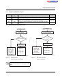
IL ETH BK DI8 DO4 2TX-PAC
Possible combinations of modes
P&P mode
Inactive
Expert
mode
Inactive
Active
Inactive
Any
Active
Diagram
Normal case - the station sets valid configurations to the RUN state. Process
data exchange is possible.
The connected configuration is stored as the reference configuration and the
station is set to the RUN state. Process data cannot be written.
The bus is not started automatically, instead it waits for firmware commands
from the user.
Figure 13 on
page 19
Figure 14 on
page 19
Startup diagrams for the bus coupler
m
11.4
Description/effect
co
11.3
s.
P o w e r u p
ne
S e P t o s w t a e tr i o U n p t o
"R U N " s ta te
Figure 13
p
P P
C O
D L E
E
in
d ia g n
S ta tio n in
"R U N " s ta te
P P L E D = O F F
C O L E D = O F F
D L E D = O N
on
l
= O F F
= O N
fla s h in g
u s e in
b u s
r e g is te r s
B M
in
ec
S e P t o s w t a e tr i o U n p t o
"R U N " s ta te
S to
P P L E D
C O L E D
D L E D =
E rro r c a
lo c a l
d ia g n o s tic
o r in W
C a n c o n fig u r a tio n b e
o p e ra te d ?
Y e s
om
Y e s
N o
po
N o
C o n fig u r a tio n =
r e fe r e n c e c o n fig u r a tio n ?
R e a d in
c o n n e c te d c o n fig u r a tio n
nt
L o a d a n d a c tiv a te
s a v e d c o n fig u r a tio n
P o w e r u p
S to
L E D
L E D
D =
rro r c
lo c a
o s tic
p
= O N
= O N
fla s h in g
a u s e
l b u s
r e g is te r s
S ta tio n in
"R U N " s ta te
P P L E D = O N
C O L E D = O F F
D L E D = O N
7 2 7 5 A 0 1 1
7 2 7 5 A 0 1 0
Standard mode/
P&P and expert mode inactive
Figure 14
P&P mode active and
expert mode inactive
When expert mode is deactivated, the bus
coupler must be restarted for the change to take
effect.
7275_en_03
PHOENIX CONTACT
19
IL ETH BK DI8 DO4 2TX-PAC
12
Switch off the supply voltage.
Change the configuration.
Switch on the supply voltage.
Monitoring
mechanism
Process data
watchdog
(process data
monitoring)
Connection
monitoring
for Modbus
and DTI
po
ne
A configuration is started as shown in the flowchart (see
Figure 13 and Figure 14). During startup, please observe
the following:
– Once the bus coupler has been switched on, the
previously found configuration is read and started, as
long as no errors are present.
– All connected Inline devices are integrated in the active
configuration if the DIAG LEDs are continuously lit on all
terminals.
– To prevent the accidental use of the wrong
configuration, process data can only be accessed when
P&P mode has been deactivated.
The monitoring functions differ according to the features/
functions that need to be monitored. Depending on the
application requirements, the appropriate monitoring
function can be activated. By default upon delivery, the
process data watchdog is activated.
m
The following steps must be carried out when changing an
existing configuration:
Monitoring functions with different features are available for
monitoring Ethernet communication.
– Process data watchdog (process data monitoring)
– Connection monitoring for Modbus (see "Modbus
connection timeout" on page 27) and DTI
on
l
in
ec
om
When P&P mode is active, access to process
data is rejected with the error message 00A9hex
(ERR_PLUG_PLAY). The outputs of the entire
Inline station are reset in P&P mode.
P&P mode is activated either using WBM, the
Modbus command register or the "Set_Value"
command via Ethernet. Once P&P mode has
been switched off, the bus is only started if the
existing configuration and the reference
configuration are the same.
7275_en_03
Monitoring …
... the
... the
... the
client indivi- Ethernet
applica- dual
connection
chantion
nels
X
–
X
s.
Ensure that plug and play mode is activated and
expert mode is deactivated.
Monitoring functions
co
Changing and starting a configuration in P&P
mode
nt
11.5
X
X
X
...
process
data exchange
X
–
In the event of an error the system responds with a fault
response. The user determines the required fault response
mode.
12.1
Setting the required fault response mode
The required fault response mode can be set via web-based
management, by writing to Modbus register 2002 or using
the "Set_Value" service for variable 2277hex. The following
fault response modes are available:
Fault
response
mode
Standard
fault mode
Reset fault
mode
(default)
Hold last
state mode
Value Function
0
All outputs are set to "0".
1
The digital outputs are set to "0".
Analog outputs are set to the default
value for the terminal.
All outputs keep their last value.
2
PHOENIX CONTACT
20
IL ETH BK DI8 DO4 2TX-PAC
12.2
Process data watchdog/
process data monitoring
NET FAIL
If there is no triggering during the timeout period, an error
occurred. Two responses follow:
– The selected fault response mode is executed
– The NetFail signal is set (the Net Fail LED is red).
By default upon delivery, the process data
watchdog is activated with a 500 ms timeout.
The reason for setting the Net Fail signal is listed in the
reason code.
co
m
For safety reasons, the user cannot stop the watchdog once
it has been activated. If the user terminates the controlling
application, there is no watchdog triggering; when the
timeout period elapses, the Net Fail signal is set and the
selected fault response mode is executed. After the
watchdog has performed its task, the outputs are only
enabled again after acknowledgment.
nt
s.
When the error is acknowledged, the watchdog is
restarted. This means that it must be triggered
during the timeout period, otherwise an error is
detected again.
Process data monitoring configuration in WBM
po
Figure 15
ne
Configuration of the process data watchdog
Process data watchdog function
om
A process data watchdog is integrated into the
IL ETH BK DI8 DO4 2TX-PAC to avoid uncontrolled setting/
resetting of the Inline station outputs in the event of an error.
When a timeout has occurred and fault response
has been activated, and Net Fail has not yet been
acknowledged.
The process data watchdog timeout period can be
configured from 200 ms to 65000 ms. Timeout periods can
be set via web-based management, by writing to Modbus
register 2000 or using the "Set_Value" service for variable
2233hex.
on
l
in
ec
If station outputs are set, the controlling process must be
able to access the station. In the event of an error, e.g.,
network line interrupted or function error in the controlling
process, the bus terminal can respond appropriately via the
process data watchdog. By default upon delivery, the
watchdog is activated with a 500 ms timeout. The first write
process activates the process data watchdog. The next
write process is expected during the timeout period (default:
500 ms). During error-free operation, the write process is
performed during the timeout period and the watchdog is
restarted (triggered).
Timeout can only be changed if the watchdog is in
INIT state. The INIT state is present:
– After power-up, as long as process data
exchange has not taken place
Reading calls do not trigger the process data
watchdog.
7275_en_03
PHOENIX CONTACT
21
IL ETH BK DI8 DO4 2TX-PAC
Deactivating the process data watchdog
Possible reasons:
The process data watchdog can only be deactivated if it is in
the INIT state. For deactivation, the timeout value is set to
zero.
P o w e r u p
"IN IT " s ta te
co
N o
s.
W a tc h d o g
T im e o u t > 0 ?
m
W r ite _ O K /
C le a r N e tF a il
ne
nt
Y e s
Y e s
N o
W a tc h d o g tim e o u t e la p s e s
S e t N e t F a il
F a u lt r e s p o n s e
Status diagram of the process data watchdog
0001hex
0002hex
0003hex
0004hex
0005hex
0006hex
0007hex
0008hex
0009hex
000Ahex
000Bhex
000Chex
000Dhex
in
ec
Figure 16
om
6 1 5 6 0 0 2 9
po
A C T IV E :
W r ite _ O K
DDI_NF_TASK_CREAT_ERR
/* Error when starting a task */
DDI_NF_LISTENER_ERR
/* Listener task error */
DDI_NF_RECEIVER_ERR
/* Receiver task error */
DDI_NF_ACCEPT_ERR
/* Accept function error */
DDI_NF_ECHO_SERVER_ERR
/* Echo server task error */
DDI_NF_HOST_CONTROLLER_ERR
/* Host controller task error */
DDI_NF_DTI_TIMEOUT
/* DTI timeout occurred */
DDI_NF_HOST_TIMEOUT
/* Host timeout occurred */
DDI_NF_USER_TEST
/* NetFail set by user */
DDI_NF_CONN_ABORT
/* Connection aborted */
DDI_NF_INIT_ERR
/* Initialization error */
DDI_NF_DTI_WATCHDOG
/* Process data watchdog triggered */
DDI_NF_MBUS_TIMEOUT
/* Modbus timeout occurred */
Fault response acknowledgment
on
l
The Net Fail signal can be acknowledged via web-based
management via Modbus, by writing command 0002hex to
command register 2006 or using the "ETH_ClrNet
FailStatus" function.
Reasons for fault response
The reasons for a fault response and a set Net Fail signal
can be accessed via web-based management, Modbus
register 2004 or the "ETH_GetNet FailStatus" service.
7275_en_03
PHOENIX CONTACT
22
IL ETH BK DI8 DO4 2TX-PAC
13
13.5
Modbus protocol
The bus coupler supports a Modbus/TCP server and a
Modbus/UDP server with the following features:
13.1
Modbus connections
The bus coupler supports up to eight Modbus/TCP
connections at the same time. In this way, a connection can
quickly be restored. This means that the client can
successfully restore an interrupted Modbus connection.
The UDP server is connectionless.
Modbus interface
s.
Modbus conformance classes
The bus coupler supports Modbus conformance class 0.
Modbus function codes
on
l
in
ec
7275_en_03
po
om
Function code
Read multiple registers
Read input registers
Write single register
Write multiple registers
Read/write registers
ne
The following function codes are supported:
Code no.
fc3
fc4
fc6
fc16
fc23
PCP
Modbus
Access
register table
(16-bit word)
6020 - 6173
Read/
write
nt
13.4
Function
Modbus connection
monitoring timeout
Process data watchdog
timeout
Fault response mode
NetFail reason
Command register
co
The Modbus interface according to standard port 502
supports Modbus communication via the bus coupler.
13.3
Special registers
Modbus
Access
register table
(16-bit word)
1280
Read/
write
2000
Read/
write
2002
Read/
write
2004
Read/
write
2006
Read/
write
m
13.2
Modbus tables
Function
See Modbus PCP registers
on page 28
Diagnostics
Modbus
Access
Function
register table
(16-bit word)
7996
Read only Status register
7997
Read only Local bus diagnostic status
register
7998
Read only Local bus diagnostic
parameter register 1
7999
Read only Local bus diagnostic
parameter register 2
Process data (dynamic table)
Modbus
Access
Function
register
table-(16-bit
words)
8000
Read only Local digital inputs
8001 Read only Bus inputs (X words)
(8000+X)
(8001+X)
Read/ Local digital outputs
write
(8002+X) Read/ Bus outputs (Y words)
(8001+X+Y)
write
PHOENIX CONTACT
23
IL ETH BK DI8 DO4 2TX-PAC
AO2
AO1
AI2
AI2
DI2
DI8
DO2
DO8
DI8 ETH BK
DO4 ETH BK
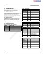
Assignment of process data
ETH BK
13.6
m
ETHERNET
RESET
LNK1
co
ACT1
X1
LNK2
s.
ACT2
nt
X2
Figure 17
7275_en_03
xx
po
Channel 1 value
Channel 2 value
Channel 1 value
Channel 2 value
om
Channel 1 status
Channel 2 status
xxxx
in
ec
DATA OUT
Address 8009
Address 8010
Address 8011
Address 8012
Address 8013
Address 8014
Address 8015
Address 8016
Address 8017
Address 8018
xxxxxxxx
xxxxxxxx
xxxxxxxx
xx
Channel 1 parameter
Channel 2 parameter
Channel 1 parameter
Channel 2 parameter
Channel 1 value
on
l
DATA IN
Address 8000
Address 8001
Address 8002
Address 8003
Address 8004
Address 8005
Address 8006
Address 8007
Address 8008
ne
Modbus register/location of process data
Channel 1 value
Channel 2 value
7275A014
Location of process data for dynamic tables
PHOENIX CONTACT
24
IL ETH BK DI8 DO4 2TX-PAC
13.7
Diagnostic registers
Bit
5
6
7
Status register
Address:
– Modbus: Register 7996
Using the Ethernet host controller, e.g., PLC, the user can
read current diagnostic information from the network
interface status word without the need for configuration
software.
The READY, ACTIVE and RUN operating indicators show
the current state of the local bus system. The diagnostic
parameter register is not used.
m
After the selftest, the local bus master is ready for operation.
The READY indicator bit is set (READY = 1).
co
If the local bus master has been configured and the
configuration frame activated without errors, the system
indicates it is active. The READY and ACTIVE indicator bits
are set (READY = 1, ACTIVE = 1).
s.
In addition, the RUN indicator bit is set when data exchange
is started (READY = 1, ACTIVE = 1 and RUN = 1).
nt
This results in the following values for the status word:
Status
Address:
– Modbus: Register 7997
po
om
Local bus diagnostic status register
ne
The errors are indicated until they are
acknowledged.
An error occurred (e.g., a bit in the
diagnostic register is set).
No error occurred.
A NetFail occurred.
0001hex
0002hex
Meaning
Exchanging data cycles
Local bus master ACTIVE
Local bus master READY, selftest
completed
Operating Indicators: READY, ACTIVE, RUN
Only the two least significant bits (bit 0 and bit 1) have a
function. Bit 2 to bit 15 are reserved.
– Bit 0 = 0: An error occurred
(e.g., a bit in the diagnostic register is set).
– Bit 0 = 1: No error
– Bit 1 = 0: No NetFail
– Bit 1 = 1: NetFail present
Register
contents
0000hex
Constant
RUN_BIT
ACTIVE_BIT
READY_BIT
Bit
0
1
2
3
4
on
l
in
ec
Each bit in the local bus diagnostic status register is
assigned a state of the local bus master on the bus coupler.
The states in the error bits (USER, PF, BUS, CTRL) are
described in greater detail using the diagnostic parameter
register. Whenever one of the error bits described above is
set, the diagnostic parameter register is rewritten.
Otherwise, the diagnostic parameter register has the value
0000hex.
Constant
USER_BIT
PF_BIT
Meaning
Application program error
Local bus device detected a
peripheral fault
BUS_BIT
Error on local bus
CTRL_BIT
Local bus master has an internal
error
DETECT_BIT Error localization
("LOOK FOR FAIL")
7275_en_03
PHOENIX CONTACT
25
IL ETH BK DI8 DO4 2TX-PAC
Error indicators: DETECT, CTRL, BUS, PF, USER
Local bus diagnostic parameter register 1
The DETECT error bit shows that an error is preventing
further operation of the local bus (DETECT = 1). The
outputs return to the set state, see page 20. The diagnostic
routine searches for the error cause.
Address:
– Modbus: Register 7998
Once the error cause has been detected, the DETECT error
bit will be reset (DETECT = 0) and the error indicated in the
USER, PF, BUS and CTRL bits. The diagnostic parameter
register and the extended diagnostic parameter register
provide a detailed description of the error cause.
For detected local bus errors, the local bus diagnostic
parameter register contains the error location:
Device number of a device,
e.g., "0.3" for bus segment 0; device 3
Error location, e.g., device number 0.3
Error with local bus shutdown
S e g m e n t n u m b e r
7
Error location
7
0
7 2 7 5 a 0 0 7
Contents of the local bus diagnostic parameter
register (example)
ne
Address:
– Modbus: Register 7999
Local bus diagnostic parameter register 2 contains
additional information about the error codes.
in
ec
om
po
Contents of the
diagnostic
parameter register
Error location
Fault on the peripheral side of a
local bus device:
– Short circuit at the output
– Sensor/actuator supply not
present
USER = 1
3
n + 1
Local bus diagnostic parameter register 2
Error without local bus shutdown
PF = 1
0
Figure 18
Error on a local bus segment.
Error bit/location
0
co
Probably local bus master/
hardware error.
BUS = 1
0
n
s.
CTRL = 1
0
P o s itio n in th e s e g m e n t
m
Contents of the
diagnostic
parameter register
Error code
nt
Error bit/location
Error code
on
l
User error, e.g., due to incorrect
parameters
7275_en_03
PHOENIX CONTACT
26
IL ETH BK DI8 DO4 2TX-PAC
NetFail reason
Special registers
Address:
– Modbus: Register 2004
To change the timeout value for the relevant TCP
connection, write the new timeout value to the timeout table
to the special address 1280 using the functions fc6 or fc16.
The value of this entry is the value of the timeout table. The
time is specified in milliseconds in the range from 200 ms to
65000 ms.
Modbus: Register 2006
The network interface command register can be used to
transmit commands with basic functions to the bus coupler
using the Ethernet host controller, e.g., PLC.
15 14 13 12 11 10 9 8 7 6 5 4 3 2 1 0
X X X
Reserved bits
Figure 19
Clear peripheral fault
Clear NetFail
Plug and play
61560030
Command word
po
Connection monitoring with the new timeout
values is only activated after a Modbus/TCP
function has been executed on the relevant TCP
connection.
–
ne
A timeout value of "0" deactivates the monitoring function.
Values between 1 ms and 199 ms, and values greater than
65000 ms generate exception response 3
(ILLEGAL DATA VALUE).
Command register
m
A monitoring mechanism can be activated for every
Modbus/TCP connection in order for the bus coupler to
detect an error on the network (e.g., faulty cable) or in the
client (operating system crash or error in the TCP/IP
protocol stack) and respond accordingly. The monitoring
mechanism is activated via the relevant TCP connection on
the first read or write procedure.
As soon as the NetFail signal is set, the cause can be read
out via this register. If there is no NetFail signal, the register
is 0.
co
Modbus: Register 1280
s.
Modbus connection timeout
nt
13.8
in
ec
om
After the first access by a Modbus/TCP function, all other
access must be carried out using the entered timeout value.
Otherwise, fault response mode is activated and the
Modbus/TCP connection is disabled.
Process data watchdog timeout
–
Modbus: Register 2000
on
l
Setting or reading the timeout value for the process data
watchdog. The time is specified in milliseconds in the range
from 200 ms to 65000 ms. A timeout value of "0" deactivates
the watchdog.
Fault response mode
–
Modbus: Register 2002
Setting or reading the fault response mode. For information
on fault response mode settings, please refer to Section
"Setting the required fault response mode" on page 20.
7275_en_03
PHOENIX CONTACT
27
IL ETH BK DI8 DO4 2TX-PAC
Modbus/TCP PCP registers
Communication
reference register
CR 2
6020
The IL ETH BK DI8 DO4 2TX-PAC supports 16 PCP
devices, therefore 16 communication registers and 24
configuration registers are supported.
CR 4
A Modbus function is only ever used for read/write access to
a PCP index. For example, the fc3 command cannot be
used to read 20 words from registers 6020 to 6039.
...
ne
The communication register contains a different value range
due to the selected values of the register and the terminal
used. Therefore, the IB IL RS 232 terminal, for example,
has three different PCP objects: two objects are one word
long, but the third is 29 words long. The three configuration
registers can be read/written with a single Modbus
command. An attempt to access a reserved register
generates an exception response.
Index
Subindex
Invoke ID
Reserved
6040
CR 16
...
CR 17
6041
6042
6043
6044 - 6049
Index
Subindex
Invoke ID
Reserved
...
...
6161
6162
6163
6164 - 6169
Index
Subindex
Invoke ID
Reserved
6171
6172
6173
6174 - 6179
Index
Subindex
Invoke ID
Reserved
6160
po
om
6031
6032
6033
6034 - 6039
6170
on
l
in
ec
Index
Subindex
Invoke ID
Reserved
6030
s.
Example: In order to read object 5FE0hex of an
IB IL RS 232 terminal with communication reference 4, first
set the configuration registers (6041 - 6043) to the desired
values with the fc16 command (e.g., 6041 index: 5FE0hex,
6042 subindex: 0hex, 6043 invoke ID: 0hex). The fc3
command can then be used to read 29 words via
communication register 6040.
Remark
6021
6022
6023
6024 - 6029
m
CR 3
Configuration
register
co
The PCP registers are divided into two classes:
– Communication registers for exchanging data with the
desired PCP device
– Configuration registers for selecting the invoke ID,
index, and subindex of the PCP device
nt
14
7275_en_03
PHOENIX CONTACT
28
IL ETH BK DI8 DO4 2TX-PAC
15
Device Driver Interface (DDI)
The IL ETH BK DI8 DO4 2TX-PAC bus coupler supports
access via the Device Driver Interface (DDI).
A driver for Windows NT, Windows 2000, and
Windows XP can be downloaded at
www.download.phoenixcontact.com under the
name "Ethernet Driver 2.0. exe". Drivers for other
operating systems are available from
Phoenix Contact on request.
co
m
Using this interface requires the appropriate driver to be
installed on the host. For a detailed description of the
services, please refer to the "Driver Reference Manual for
G4-Based Controller Boards Using PC Bus and Ethernet",
see page 3.
15.2
ETH_SetDTITimeoutCtrl ( )
ETH_ClearDTITimeoutCtrl ( )
ETH_SetNet Fail ( )
ETH_GetNet FailStatus ( )
ETH_ClrNet FailStatus ( )
ETH_SetNet FailMode ( )
ETH_GetNet FailMode ( )
15.3
–
–
nt
ne
Connection and error monitoring
in
ec
–
–
–
–
–
–
–
po
DDI_DevOpenNode ( )
DDI_DevCloseNode ( )
DDI_DTI_ReadData ( )
DDI_DTI_WriteData ( )
DDI_DTI_ReadWriteData ( )
DDI_MXI_SndMessage ( )
DDI_MXI_RcvMessage ( )
GetIBSDiagnostic ( )
on
l
–
–
–
–
–
–
–
–
Services for remote access to the DDI
om
15.1
s.
The following services are supported:
Services for process data monitoring
ETH_ActivatePDinMonitoring ( )
ETH_DeactivatePDinMonitoring ( )
7275_en_03
PHOENIX CONTACT
29
IL ETH BK DI8 DO4 2TX-PAC
AO1
AO2
DI8
AI2
DO8
AI2
DO4 DI8
ETH ETH
BK BK
ETH
BK
DI2
Assignment of process data
DO2
15.4
ETHERNET
LNK1
m
RESET
ACT1
LNK2
co
X1
ACT2
nt
s.
X2
Address/location of process data
Byte (x+1)
xxxxxxxx
Byte 2
xxxxxxxx
Channel 1 value
Byte 8
Channel 2 value
Byte 10
Channel 1 value
Channel 2 value
Byte 14
Channel 1 status
Byte 16
Channel 2 status
Byte 0
Byte 2
Byte 4
Byte 6
DATA OUT Byte
8
xxxx
xxxxxxxx
xx
Channel 1 parameter
Channel 2 parameter
Channel 1 parameter
on
l
Byte 10
in
ec
Byte 12
om
Byte 6
po
xx
Byte 4
DATA IN
ne
Byte x
Byte 0
Figure 20
7275_en_03
Byte 12
Channel 2 parameter
Byte 14
Channel 1 value
Byte 16
Channel 1 value
Byte 18
Channel 2 value
7275A013
Assignment of process data
PHOENIX CONTACT
30
IL ETH BK DI8 DO4 2TX-PAC
16
Firmware services
As it is not necessary to use each firmware service in both
operating modes (expert mode active/inactive), the
following table indicates the assignment of the services to
the operating modes. If the services are not used as
specified in the table, this may cause the firmware to behave
as follows:
030Bhex
Complete_Read_Configuration
0315hex
Read_Device_State
0316hex
032Ahex
032Bhex
Get_Error_Info
Get_Version_Info
Get_Diag_Info
0351hex
0714hex
Read_Value
Control_Device_Function
0750hex
0760hex
0956hex
Set_Value
Confirm_Diagnostics
Reset_Controller_Board
Function
Reads various entries of the configuration directory
Used_Attributes: 0002hex = Device code
Reads all device data for a configuration
Used_Attributes: 0002hex = Device code
Reads status of local bus devices
Device_State_Mask: 0008hex = Peripheral fault
Requests additional error information
Reads version information
Reads local bus counters
Diag_Info_Attr: 0004hex = Global_Count
Reads system parameters
Sends control commands to local bus devices
Device_Function:
0003hex = Conf_Dev_Err
0004hex = Conf_Dev_Err_All
Assigns new values to system parameters
Updates the diagnostic display and registers
Resets the controller board
m
Services
Read_Configuration
2.
The service is not permitted in this mode and is rejected
with a negative acknowledgment.
The service is executed and terminated with a positive
acknowledgment. The effect of this service is removed
by the firmware. Supported firmware services that can
be used in every operating mode:
om
po
ne
nt
s.
co
Code
0309hex
1.
in
ec
Supported firmware services that are only available in expert mode:
Services
Initiate_Load_Configuration
Load_Configuration
030Ahex
Complete_Load_Configuration
on
l
Code
0306hex
0307hex
Terminate_Load_Configuration
0308hex
Delete_Configuration
Control_Parameterization
Start_Data_Transfer
Create_Configuration
Activate_Configuration
Alarm_Stop
030Chex
030Ehex
0701hex
0710hex
0711hex
1303hex
Function
Loads a configuration frame (extension not supported)
Transmits the device data for a configuration
Used_Attributes: 0002hex = Device code
Transmits all device data for a configuration
Used_Attributes: 0002hex = Device code
Terminates the transmission of configuration data
only for automatic parameterization
Deletes a configuration
Starts or ends the parameterization phase
Starts data transmission
Reads in the connected configuration
Compares the saved and connected configuration
Resets the local bus
For additional information about firmware services, please refer to the IBS SYS FW G4 UM E user manual.
7275_en_03
PHOENIX CONTACT
31
IL ETH BK DI8 DO4 2TX-PAC
System parameters for the "Set_Value" (750hex) and "Read_Value" (351hex) services
Expert mode (32-bit word)
2277hex
2293hex
Fault response mode (32-bit word)
Process data watchdog timeout (32-bit word)
PCP communication
17.1
Transmission of parameter data
17.2
The MXI interface of the DDI can be used to send the
following PCP commands.
Service
Initiate_Request
Abort_Request
Read_Request
Write_Request
Information_Report_Request
Status_Request
Identify_Request
Load_Kbl_Par_Loc_Request
Read_Kbl_Loc_Request
po
ne
Intelligent devices such as frequency inverters or controllers
exchange process data with each other and also exchange
larger volumes of data with the control system. Such data
can, for example, be used for the startup phase of a
machine. This type of parameter data rarely changes and is
transmitted when necessary.
Supported PCP commands
nt
17
m
2275hex
Value/Comment
Read only
Read only
Read only
Read only
0: Plug and play mode inactive
1: Plug and play mode active
0: Expert mode inactive
1: Expert mode active
See page 20
See page 21
om
The INTERBUS protocol can transmit process data and
complex data records (parameter data) at the same time.
The comprehensive parameter data is divided into smaller
units, transmitted and then recombined.
in
ec
With INTERBUS, the Peripherals Communication Protocol
(PCP) divides the parameter data into individual segments.
After the transmission it recombines the data. The protocol
software is called PCP. This software provides the
necessary services for connection establishment and
connection abort, etc.
co
System parameter
Diagnostic status register (16-bit word)
Diagnostic parameter register 1 (16-bit word)
Diagnostic parameter register 2 (16-bit word)
Current PD cycle time (32-bit word)
Plug and play mode (32-bit word)
s.
Variable ID
0104hex
0105hex
010Dhex
2216hex
2240hex
Service code
008Bhex
088Dhex
0081hex
0082hex
0885hex
0083hex
0087hex
0264hex
0203hex
on
l
For detailed information on PCP communication,
please refer to the IBS SYS PCP G4 UM E user
manual.
Please note that a maximum of 16 PCP terminals
can be connected to a bus coupler.
7275_en_03
PHOENIX CONTACT
32
IL ETH BK DI8 DO4 2TX-PAC
17.3
Configuration of the PCP PDU size
18
The standard PDU size for communication with all
Phoenix Contact Inline devices is 64 bytes in the transmit
and receive direction.
Simple Network Management
Protocol (SNMP)
The bus coupler supports SNMP v1 and v2c.
System couplers such as the ILC 200 UNI have
configurable PDU sizes. If another size is configured and an
IL ETH BK DI8 DO4 2TX-PAC is used for communication,
the bus coupler must also be configured to the values
already set on the ILC 200 UNI.
Management Information Base - MIB
The latest MIBs can be found on the Internet at
www.download.phoenixcontact.com.
m
For the object descriptions, please refer to the ASN1
descriptions of this product. They can be downloaded from
Internet at www.download.phoenixcontact.com.
PCP configuration in web-based management
on
l
in
ec
Figure 21
om
po
ne
nt
s.
co
The password for read access is "public" and cannot be
modified. By default upon delivery, the password for read/
write access is "private" and can be modified at any time.
7275_en_03
PHOENIX CONTACT GmbH & Co. KG • 32823 Blomberg • Germany • Phone: +49-(0) 5235-3-00
PHOENIX CONTACT • P.O.Box 4100 • Harrisburg • PA 17111-0100 • USA • Phone: +717-944-1300
www.phoenixcontact.com
33