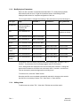
1
Video GUI
Video Matrix Graphic User Interface
User Manual
900.0412 - June 2005 - Rev. 1
ISSUE
DATE
1
June 2005
Rev. 1
REVISIONS
Initial Release
ii
900.0412
27-June-05
TABLE OF CONTENTS
1.1
OVERVIEW.................................................................................................................................... 1
2.1
OPERATING ENVIRONMENT REQUIREMENTS.......................................................................... 3
2.1.1 Hardware Requirements .................................................................................................. 3
2.1.2 Software Requirements.................................................................................................... 3
3.1
INSTALLATION ............................................................................................................................. 5
3.1.1 Obtaining a System Unlock Code ................................................................................... 5
3.1.2 Setting up Operating Preferences ................................................................................... 5
4.1
USER OPERATION ....................................................................................................................... 6
4.1.1 Starting the Program........................................................................................................ 6
4.1.2 Selecting a Monitor Output .............................................................................................. 6
4.1.3 Selecting a Camera Input ................................................................................................ 7
4.1.4 Controlling a PTZ Camera ............................................................................................... 7
4.1.5 Controlling a Video Cassette Recorder ........................................................................... 7
4.1.6 Controlling a Multiplexer .................................................................................................. 7
4.1.7 Opening a New Area for Display / Closing Area Display................................................. 7
4.1.8 Opening a New Site for Display / Closing Site Display ................................................... 7
4.1.9 Setting User Preferences ................................................................................................. 8
5.1
CONFIGURATION......................................................................................................................... 8
5.1.1 Entering Configuration Mode........................................................................................... 8
5.1.2 Adding Bitmaps, Metafiles and Icons .............................................................................. 8
5.1.3 Modifying Icon Parameters .............................................................................................. 9
5.1.4 Adding Areas.................................................................................................................... 9
5.1.5 Adding Sites................................................................................................................... 10
Rev. 1
iii
900.0412
27-June-05
Notes:
Rev. 1
iv
900.0412
27-June-05
1.1 OVERVIEW
The Honeywell VideoGUI is a program, which allows for control of the Honeywell Video
Matrix system from a PC platform.
Various displays may be set up to suit the requirements of the installation.
Rev. 1
1
900.0412
27-June-05
Notes:
Rev. 1
2
900.0412
27-June-05
2.1 OPERATING ENVIRONMENT REQUIREMENTS
2.1.1
Hardware Requirements
Hardware requirements for the PC on which the VideoGUI is to be installed are as
follows:
Hardware
Minimum
Recommended
Processor
80486
Pentium 166 MHz or better
RAM
8 MB
16 Mbyte or more
Hard Disk (free before install) 5 MB
50 Mbyte or more
Display
640 X 480 VGA
800 X 600 or better
Mouse
Required
Required
Installation disks may be ordered on
1.44 MB stiffy disks, but the standard
software is supplies on CD ROM
CD ROM
Network Adaptor
2.1.2
Required if more than 1 operating
point is to be used.
Yes
Required if more than 1 operating
point is to be used.
Software Requirements
The PC must be preloaded with a 32 bit version of Windows. This may be Windows 95,
Windows 98 or Windows NT. For systems with more than 1 VideoGUI, operating via a
network, the PC’s must have networking software for TCP/IP installed. Networked
systems also require the Betatech CCTV Server software package.
Configuration of the various maps to be displayed may be done in a variety of ways.
Tools which can generate / edit Windows Bitmap (.BMP), Windows Metafile (.WMF) and
Windows Enhanced Metafile formats are useful. The simplest tool would be the “Paint”
utility which is supplied with Windows. Other programs would be Corel Photo Paint or
Photo Express (Ulead Systems inc.). Often plans for sites are available in Drawing
Interchange Format (.DXF). To convert such files to bitmaps or Metafiles, AutoCad 12 or
later would be useful. The system also utilises database files in Paradox 7 format for
storing information on views and sites. Advanced editing features of the databases could
be carried out using Paradox 7.
Rev. 1
3
900.0412
27-June-05
Notes:
Rev. 1
4
900.0412
27-June-05
3.1 INSTALLATION
Insert the Honeywell distribution CD ROM into a CD ROM drive. Run the “Setup.exe”
program in the “VideoGUI” subdirectory on the CD. To install from stiffy disk (1.44 MB),
insert Disk 1 of the installation set into the disk drive and run the program “Setup.exe”
from the disk. To run the program, select “Start”, then choose “Run” on the menu which
appears. The program “Setup.exe” may be located by using the “Browse” option.
The installation program provides a number of options. Generally the default option will
work correctly and this may be accepted by pressing “Next”. Note that the serial number
will be required for program operation and this may be obtained from the label on the
CD ROM or stiffy disk.
Set up a shortcut to the program using one of the standard Windows techniques or start
the program by selecting “Start”, “Programs”, “VideoGUI” and then select “VideoGUI”.
Note that until the required system unlock code has been entered, the VideoGUI will
operate only in demonstration mode. The unlock code is a unique number, based on the
software serial number and the hard disk serial number. To obtain the hard disk serial
number, use “Run”, “Programs”, “MS-DOS Prompt”. At the command line type “Vol” and
press “Enter”. The hard disk serial number is displayed, e.g., “64D3-09FC”. To unlock
the VideoGUI, run the VideoGUI as described above and select “Configure”,
“System…”, “Security”. The hard disk serial number will be displayed, together with
fields for the “Serial Number” and “Unlock Code”. Enter the serial number and unlock
code and then press the “Check Code” button. When the “Unlock Code” box changes
from red to green, the correct code has been entered.
3.1.1
Obtaining a System Unlock Code
Registered users may obtain unlock codes from Betatech or from the distributor from
which the product was purchased. If the hard disk serial number is provided prior to
purchase of the product, then the unlock code will be shipped with the software. Should
it be necessary to obtain a new code, due to moving the product to another PC or
replacement of the hard disk, additional codes may be obtained as described above.
Using a single copy of the program simultaneously on more than 1 PC, when only a
single license has been purchased, will be seen as being a breach of the copyright of
the product.
3.1.2
Setting up Operating Preferences
Operating preferences are selected by means of the “Settings” page of the configuration
screens. Select the default site which is to be displayed when the program starts by
changing the “Default Site” name. This may be typed in or selected by choosing “Set”
and then selecting the required site.
The VideoGUI operates the Betatech video matrix via the RS232 port and simulates the
operation of a dedicated control keyboard (PCK). The “Keyboard Num” field on the
“Settings” page must be set either to the number of a keyboard which is not used on the
system (in the range 1 to 16), or to the number of the keyboard which will be operated in
conjunction with the VideoGUI.
Rev. 1
5
900.0412
27-June-05
3.1.2
Setting up Operating Preferences, Continued
Communications with the matrix are set up by choosing the “Communications” button
on the “Settings” page.
For systems which are connected directly to the matrix (serial number VGUI-xxxxxx-yyy),
set the required communications port to match the number of the port to which the video
matrix is attached. The default communication parameters of the matrix ore 19.2KB and
2 stop bits, so these options will generally remain unchanged.
For networked communications using Windows TCP/IP networking (serial number NGUIxxxxxx-yyy), check the “Use Network Communications” option. Enter either the host
TCP/IP network address or the host name, as well as the host network port number. This
information may be obtained from the diagnostic display screen of the CCTV Server
package.
After changing communications parameters, or setting the unlock code, it is strongly
recommended that the user exit the program and restart it.
There are two levels of password protection on the VideoGUI. The system will prompt for
a password should either password be configured. Should the user password be
entered when the program is started, then the system will not allow any of the
configuration options to be selected. Should the mater password be used, then
configuration options are available. Password may be changed using the “User
Password” and “Master Password” buttons on the configuration “Security” page.
4.1 USER OPERATION
4.1.1
Starting the Program
Set the VideoGUI by double clicking on the shortcut icon by selecting “Start”,
“Programs”, “VideoGUI” and then select “VideoGUI”.
Enter the user password in the displayed box and press enter or the “OK” button. The
configured start up screen will be displayed. Note that the system automatically
remembers the size and position of the VideoGUI main window from the last time the
program was shut down. The display may be resized by clicking on the bottom right
corner of the main window and “dragging” it to a new size using the mouse. The main
window may be moved around the screen by clicking on the top caption bar and
dragging it to a new location.
If the displayed area is larger than the area allowed based on the sizing of the main
window, it is possible to view different parts of the displayed area by clicking / dragging
the scroll bars located to the right and bottom of the area.
4.1.2
Selecting a Monitor Output
Select an output of the video matrix switcher by clicking on a video monitor icon. All
subsequent camera switch operations will be to the selected monitor.
Rev. 1
6
900.0412
27-June-05
4.1.3
Selecting a Camera Input
A camera input may be selected to be routed via the video matrix to the active monitor
by clicking on the camera, dome or PTZ icon associated with that camera.
When the mouse moves over a camera, dome or PTZ icon, the system allows for
selecting this camera to a dedicated video monitor output. For this quick selection to
operate, the matrix must be set up so that the associated keyboard is configured for a
dedicated monitor. Also fast selection must be enabled as described in section 4.9.
4.1.4
Controlling a PTZ Camera
To control the PTZ operation of a dome or PTZ, double click on it’s icon. Camera
operation is achieved by dragging the joystick symbol and / or clicking the zoom, focus
and iris buttons.
To recall a preset position, click the “Recall” drop down arrow and then select the
required preset position. To store the current PTZ position as a preset, press the “Store”
button, enter the required preset position number, and then press OK.
4.1.5
Controlling a Video Cassette Recorder
VCRs may be configured to auto select when their icon is clicked. In this case, when
configured as an input, the VCR will be automatically routed to the active monitor when
clicked. When configured as an output, the VCR becomes the active “monitor”, to which
selected video inputs will be routed.
Double clicking on the VCR icon brings up a VCR control panel. Operation of the various
functions is achieved by pressing the appropriate buttons. When the VCR control
operations are complete, press the “X” on the top right of the VCR control panel to close
the control panel.
4.1.6
Controlling a Multiplexer
Operation is identical to the VCR as described above, except that a Multiplexer control
panel is displayed.
4.1.7
Opening a New Area for Display / Closing Area Display
Different areas may be opened by selecting “File”, “Open Area” and then selecting the
required area file. Areas may be closed by selecting “File”, “Close”. This removes the
tab display for the selected area. It is possible to combine the above two operations by
selecting “File”, “Replace Area” and selecting the required area file. This causes the
previous area view to be removed and the required area view displayed.
It is possible to display icons which represent different areas on the screen. Clicking on
the icon will cause the tab which contains the required area to be selected. If the area
was not currently displayed on a tab, a new tab with the required area will be displayed.
4.1.8
Opening a New Site for Display / Closing Site Display
A site consists of a number of areas, each are has a tab associated with it. Selecting a
new site by “File”, “Open Site” causes all tabs to be closed and new tabs for the
required site to be displayed.
Rev. 1
7
900.0412
27-June-05
4.1.9
Setting User Preferences
Various parameters may be set up by the user and these will be automatically saved and
restored between different sessions with the VideoGUI. These options are selected by
“Configure”. Each option is displayed with a check mark, indicating that the option is
selected.
“Enable Name Display” causes the text associated with each icon to be displayed as a
hint when the mouse cursor moves over the icon.
“Enable Fast Select” causes the camera to be routed to the dedicated monitor for the
keuboard if this has been set up on the matrix.
5.1 CONFIGURATION
The ease of use of this program is largely dependent on how accurately the display
matches the real world site. It is therefore worth spending the time on generating a well
thought out setup.
To access the configuration options, it is necessary to log into the program using the
“Master” password. All operator functions as described in section 4 are available.
Additionally the configuration options described under “Installation” are available.
Note that area and site configuration information is stored in Paradox 7 database format.
The sites are saved with a .DBS extension, which must be changed to .DB if Paradox is
to access the information.
5.1.1
Entering Configuration Mode
In order to edit areas and sites, it is necessary to enter configuration mode. To do this
select “Edit”, “Enable”. A toolbar will appear which contains a set of icons representing
cameras, monitors, VCRs etc. will appear.
5.1.2
Adding Bitmaps, Metafiles and Icons
To add a new icon, click on the required item from the toolbar. If the required item is not
displayed, click “Add Image”. Note that “Add Image” automatically creates a new icon
which is the same as the icon previously edited (see 5.3.). Icons may readily be modified
as described in 5.3.
Displayed icons may be moved by clicking and dragging to the required location.
Rev. 1
8
900.0412
27-June-05
5.1.3
Modifying Icon Parameters
Each icon has a number of properties associated with it. To modify these properties,
either double click the icon, or right-click it with the mouse. A edit dialog will be
displayed which allows for complete configuration of the icon.
The icon type selection changes the meaning of the parameters as per the following list:
Icon Type
Background
Image
Parameter 1
Parameter 2
Bitmap, Metafile or
enhanced metafile to
be used for the
background
String Parameter
Name of area
database to display
Area
Icon to indicate area
Camera
Icon to indicate camera Matrix Camera Num
PTZ Camera
Icon to indicate PTZ
Monitor
Icon to indicate monitor Matrix Monitor Num
VCR
Icon to indicate VCR
Matrix Input Num
Matrix Output Num
Device number
VCR (Time
Lapse)
Icon to indicate VCR
Matrix Input Num
Matrix Output Num
Device number
Multiplexer
Icon to indicate MUX
Matrix Input Num
Matrix Output Num
Device number
Multiplexer
(Baxall)
Icon to indicate MUX
Matrix Input Num
Matrix Output Num
Device number
Matrix Camera Num
The position of the icon display may be modified by changing the “X Position” and “Y
Position”. To prevent the icon from being dragged, select “Lock Position”
Icons / backgrounds are displayed in the order that they were created. To change the
area use the 4 buttons to move the icon to the back, back 1, forward 1 or to the front.
This can be used to prevent backgrounds from hiding icons.
To erase an icon, select the “Delete” button.
Note that area files are not updated automatically and that for changes to be saved to
the disk file it is necessary to select “File” “Save Area” or “Save Area As”
5.1.4
Adding Areas
To add a new area, select “File”, “New Area”. Edit the area and then save it.
Rev. 1
9
900.0412
27-June-05
5.1.5
Adding Sites
To add a new site, select “File”, “New Site”. Note that this closes the previous site and
area databases and that changes are NOT saved automatically.
To set up a site, open the areas required in the order that the tabs should appear. Then
save the site. To use this as the site which is automatically displayed when the program
starts, set the name for the site under “Configure”, “System”, “Settings”, “Default Site”.
Rev. 1
10
900.0412
27-June-05
Notes:
Rev. 1
11
900.0412
27-June-05
Honeywell Video Systems (Head Office)
2700 Blankenbaker Pkwy, Suite 150
Louisville, KY 40299
www.honeywellvideo.com
TEL+1-800-796–2288
Honeywell Security Australia Pty Ltd.
Unit 5, Riverside Centre, 24-28 River Road West
Parramatta, NSW 2150, Australia
www.ademco.com.au
TEL +61-2-8837-9300
Honeywell Video Systems UK Ltd.
Aston Fields Road, Whitehouse Ind Est
Runcorn, Cheshire, WA7 3DL, UK
www.security.honeywell.com
TEL +44-1928-754-000
Honeywell Security Asia Pacific
Flat A, 16/F, CDW Building, 388 Castle Peak Road
Tsuen Wan, N.T., Hong Kong
www.security.honeywell.com/hk
TEL +852-2405-2323
Honeywell Security South Africa
Unit 6 Galaxy Park, Galaxy Avenue, Linbro
Business Park
P.O. Box 59904, Kengray, 2100, South Africa
www.honeywell.co.za
TEL +27-11-574-2500
Honeywell Security France
Parc Gutenberg, 13, Voie La Cardon
91120, Palaiseau, France
www.ademco.fr
TEL +33-1-6932-1090
Honeywell Security Germany
Großenbaumer Weg 8
40472 Düsseldorf, Germany
www.honeywell-security.de
TEL +49-211-415-090
Honeywell Security Italia SpA
Via della Resistenza 53/59, 20090 Buccinasco
Milan, Italy
www.ademco.it
TEL +39-02-457-1791
Honeywell Security Poland
Chmielewskiego 22a, 70-028
Szczecin, Polska
www.ultrak.pl
TEL +48-91-485-40-60
Honeywell Security Espana
Calle Vivero, 5, 28040
Madrid, Spain
www.ademco.es
TEL +34-91-533-4706
Honeywell Security Czech Republic
Havránkova 33, Brno
Dolní Heršpice, 619 00, Czech Republic
www.olympo.cz
TEL +420-543-558-111
Honeywell Security House (Netherlands)
Amperestraat 41
1446 TR Purmerend, Netherlands
www.SecurityHouse.nl
TEL +31-299-419-000
Honeywell Security Slovakia Republic
Vajnorskà 142, 83104 Bratislava
Slovakia
www.olympo.sk
TEL +421-2-444-54-660
Video Systems
www.honeywellvideo.com
1-800-796-CCTV (North America only)
© 2005 Honeywell International Inc.
All rights reserved. No part of this publication may be reproduced by any means without written permission from
Honeywell Video Systems. The information in this publication is believed to be accurate in all respects. However,
Honeywell Video Systems cannot assume responsibility for any consequences resulting from the use thereof. The
information contained herein is subject to change without notice. Revisions or new editions to this publication may
be issued to incorporate such changes.