1
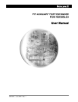
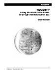
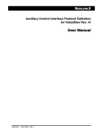
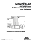
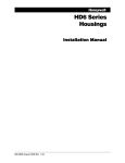
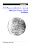
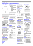
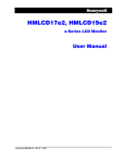
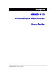
HVB16TPTX HVB16TPTX-KT UTP Video Transmitter User Manual 900.0571 - November 2005 – Rev. 1.01 ISSUE DATE REVISIONS HVBMU001133 A May 2005 Initial Release (PCN 1918) 900.0571 1 September 2005 Add HVB16TPTX-KT and HVB16TPTX-KTX (EC03485) 1.01 November 2005 Revise contents of HVB16TPTX and remove HVB16TPTXKTX Rev. 1.01 ii 900.0571 16-Nov-05 FCC COMPLIANCE STATEMENT INFORMATION TO THE USER: This equipment has been tested and found to comply with the limits for a Class A digital device, pursuant to part 15 of the FCC rules. These limits are designed to provide reasonable protection against harmful interference when the equipment is operated in a commercial environment. This equipment generates, uses, and can radiate radio frequency energy and, if not installed and used in accordance with the instruction manual, may cause harmful interference to radio communications. Operation of this equipment in a residential area is likely to cause harmful interference in which case the user will be required to correct the interference at his own expense. CAUTION: Changes or modifications not expressly approved by the party responsible for compliance could void the user’s authority to operate the equipment. CANADIAN COMPLIANCE STATEMENT This Class A digital apparatus complies with Canadian ICES-003. Cet appareil numérique de la Classe A est conforme à la norme NMB-003 du Canada. USERS OF THE PRODUCT ARE RESPONSIBLE FOR CHECKING AND COMPLYING WITH ALL FEDERAL, STATE, AND LOCAL LAWS AND STATUTES CONCERNING THE MONITORING AND RECORDING OF VIDEO AND AUDIO SIGNALS. HONEYWELL VIDEO SYSTEMS SHALL NOT BE HELD RESPONSIBLE FOR THE USE OF THIS PRODUCT IN VIOLATION OF CURRENT LAWS AND STATUTES. Rev. 1.01 iii 900.0571 16-Nov-05 Rev. 1.01 iv 900.0571 16-Nov-05 IMPORTANT SAFEGUARDS 1. READ INSTRUCTIONS – All safety and operating instructions should be read before the unit is operated. 2. RETAIN INSTRUCTIONS – The safety and operating instructions should be retained for future reference. 3. HEED WARNINGS – All warnings on the unit and in the operating instructions should be adhered to. 4. FOLLOW INSTRUCTIONS – All operating and use instructions should be followed. 5. CLEANING – Unplug the unit from the outlet before cleaning. Do not use liquid cleaners or aerosol cleaners. Use a damp cloth for cleaning. 6. ATTACHMENTS – Do not use attachments not recommended by the product manufacturer as they may result in the risk of fire, electric shock, or injury to persons. 7. WATER AND MOISTURE – Do not use this unit near water or in an unprotected outdoor installation, or any area which is classified as a wet location. 8. ACCESSORIES - Do not place this product on an unstable cart, stand, tripod, bracket, or table. The product may fall, causing serious injury to a child or adult and serious damage to the equipment. Use only with a cart, stand, tripod, bracket, or table recommended by the manufacturer, or sold with the product. Any mounting of the product should follow the manufacturer’s instructions and should use a mounting accessory recommended by the manufacturer. Wall or shelf mounting should follow the manufacturer’s instructions and should use a mounting kit approved by the manufacturer. 9. A product and cart combination should be moved with care. Quick stops, excessive force, and uneven surfaces may cause the product and cart combination to overturn. 10. VENTILATION - Slots and openings in the cabinet and the back or bottom are provided for ventilation and to ensure reliable operation of the equipment and to protect it from overheating. These openings must not be blocked or covered. The openings should never be blocked by placing the product on a bed, sofa, rug, or other similar surface. Equipment should never be placed near or over a radiator or heat register. This product should not be placed in a built-in installation, such as a bookcase or rack unless proper ventilation is provided or the manufacturer’s instructions have been adhered to. 11. POWER SOURCES – This product should be operated only from the type of power source indicated on the marking label. If you are not sure of the type of power supplied to your facility, consult your product dealer or local power company. 12. GROUNDING OR POLARIZATION – The unit must be connected to a good earth ground. 13. OVERLOADING – Do not overload outlets and extension cords as this can result in a risk of fire or electric shock. 14. POWER-CORD PROTECTION – Power supply cords should be routed so that they are not likely to be walked on or pinched by items placed upon or against them, paying particular attention to cords and plugs, convenience receptacles, and the point where they exit from the monitor. Rev. 1.01 v 900.0571 16-Nov-05 15. OBJECT AND LIQUID ENTRY – Never push objects of any kind into this unit through openings as they may touch dangerous voltage points or short-out parts that could result in a fire or electric shock. Never spill liquid of any kind on the unit. 16. SERVICING – Do not attempt to service this unit yourself as opening or removing covers may expose you to dangerous voltage or other hazards. Refer all servicing to qualified service personnel. 17. DAMAGE REQUIRING SERVICE – Unplug the unit from the outlet and refer servicing to qualified service personnel under the following conditions: a. When the power-supply cord or plug is damaged. b. If liquid has been spilled, or objects have fallen into the unit. c. If the unit has been exposed to rain or water. d. If the unit does not operate normally by following the operating instructions. Adjust only those controls that are covered by the operating instructions as an improper adjustment of any controls may result in damage and will often require extensive work by a qualified technician to restore the unit to its normal operation. e. If the unit has been dropped or the enclosure has been damaged. f. When the unit exhibits a distinct change in performance - this indicates a need for service. 18. REPLACEMENT PARTS – When replacement parts are required, be sure the service technician has used replacement parts specified by the manufacturer or have the same characteristics as the original part. Unauthorized substitutions may result in fire, electric shock or other hazards. 19. SAFETY CHECK – Upon completion of any service or repairs to this unit, ask the service technician to perform safety checks to determine that the unit is in proper operating condition. 20. LIGHTNING AND POWER LINE SURGES – For added protection of this unit during a lightning storm, or when it is left unattended and unused for long periods of time, unplug it from the wall outlet and disconnect the cable system. This will prevent damage to the unit due to lightning and power-line surges. 21. HEAT – The product should be situated away from heat sources such as radiators, heat registers, stoves, or other products (including amplifiers) that produce heat. 22. INSTALLATION – Do not install the unit in an extremely hot or humid location, or in a place subject to dust or mechanical vibration. The unit is not designed to be waterproof. Exposure to rain or water may damage the unit. 23. WALL OR CEILING MOUNTING – The product should be mounted to a wall or ceiling only as recommended by the manufacturer Rev. 1.01 vi 900.0571 16-Nov-05 EXPLANATION OF GRAPHICAL SYMBOLS The lightning flash with arrowhead symbol within an equilateral triangle is intended to alert the user to the presence of uninsulated "dangerous voltage" within the product's enclosure that may be of sufficient magnitude to constitute a risk of electric shock to persons. The exclamation point within an equilateral triangle is intended to alert the user to the presence of important operating and maintenance (servicing) instruction in the literature accompanying the product. CAUTION CAUTION RISK OF ELECTRIC SHOCK DO NOT OPEN CAUTION: TO REDUCE THE RISK OF ELECTRIC SHOCK, DO NOT REMOVE COVER (OR BACK). NO USER-SERVICEABLE PARTS INSIDE. REFER SERVICING TO QUALIFIED SERVICE PERSONNEL. WARNING WARNING: TO REDUCE THE RISK OF FIRE OR ELECTRIC SHOCK, DO NOT EXPOSE THIS PRODUCT TO RAIN OR MOISTURE. WARNING: DO NOT INSERT ANY METALLIC OBJECT THROUGH VENTILATION GRILLS . WARNING: THIS UNIT MUST BE OPERATED WITH A PROPERLY GROUNDED 3-PIN CONNECTION. NON-OBSERVANCE OF THIS STANDARD PRACTICE MAY RESULT IN A STATIC ELECTRICITY BUILD-UP THAT MAY RESULT IN AN ELECTRIC SHOCK WHEN EXTERNAL CONNECTIONS ARE TOUCHED. Rev. 1.01 vii 900.0571 16-Nov-05 Notes: Rev. 1.01 viii 900.0571 16-Nov-05 TABLE OF CONTENTS SECTION 1: INTRODUCTION ................................................................................................................ 1 1.1 PRODUCT DESCRIPTION............................................................................................................ 1 1.2 PACKAGE CONTENTS................................................................................................................. 1 SECTION 2: CONNECTIONS ................................................................................................................ 3 2.1 HVB16TPTX REAR PANEL ........................................................................................................... 3 2.2 RJ45 PIN CONNECTIONS............................................................................................................ 4 2.3 SYSTEM BLOCK DIAGRAM.......................................................................................................... 4 SECTION 3: CONTROLS AND OPERATION ........................................................................................ 5 3.1 HVB16TPTX FRONT PANEL......................................................................................................... 5 3.2 OPERATION.................................................................................................................................. 6 SECTION 4: SPECIFICATIONS ............................................................................................................. 7 LIST OF FIGURES Figure 1. HVB16TPTX Rear Panel.................................................................................................................. 3 Figure 2. RJ45 Plug Connector (Shown with Tab Underneath) .................................................................... 4 Figure 3. System Block Diagram ................................................................................................................... 4 Figure 4. HVB16TPTX FRONT PANEL........................................................................................................... 5 LIST OF TABLES Table 1: Rear Panel Connections .................................................................................................................. 3 Table 2: Front Panel Controls ........................................................................................................................ 5 Rev. 1.01 ix 900.0571 16-Nov-05 Notes: Rev. 1.01 x 900.0571 16-Nov-05 SECTION 1: INTRODUCTION 1.1 PRODUCT DESCRIPTION The HVB16TPTX and HVB16TXTXX are active video transmitters that provide for connection of 16 cameras using conventional coaxial cable with BNC connectors and converts the video signal for connection to unshielded twisted pair cabling. The twisted pair connections are RJ45 plugs. Each RJ45 plug provides 4 video outputs for twisted pair cabling and allows simple connection to a punch-down block. A switch is provided on the front panel for each video input channel for selection of short cable distances (0-1500 feet) and long cable distances (1500-3000 feet). 1.2 PACKAGE CONTENTS HVB16TPTX 1. HVB16TPTX, 16-Channel UTP Video Transmitter 2. Installation Manual, 900.0571 HVB16TPTX-KT 1. HVB16TPTX, 16-Channel UTP Video Transmitter 2. Transformer, Plug-in, 120Vac/60Hz Input, 18Vac/50VA Output, part number N8167 3. Installation Manual, 900.0571 Rev. 1.01 1 900.0571 16-Nov-05 Notes: Rev. 1.01 2 900.0571 16-Nov-05 SECTION 2: CONNECTIONS 2.1 HVB16TPTX REAR PANEL Input 16 Input 15 Power Input 14 Input 13 Input 12 Input 11 Output 13-16 Input 10 Input 9 Output 9-12 Input 8 Input 7 Input 6 Input 5 Input 4 Output 5-8 Input 3 Input 2 Input 1 Output 1-4 16-24 VAC/DC 0.4 Amps Figure 1. HVB16TPTX Rear Panel Table 1: Rear Panel Connections Connector Description Power (16-24VAC/DC, 0.4 Amps) Connect the power supply provided with the unit at the Power connector. Video Input 16 – 1: Connect cameras using conventional coaxial cable with BNC Connectors (maximum cable length = 3000 feet) Input 16 – Input 1 (BNC connectors) Output 1-4 (RJ45 Plug) Video Outputs 1-4: Connect using UTP (unshielded twisted pair) Standard CAT5 Straight-Through Ethernet Cable Camera 1 = Pins 4 & 5 Camera 2 = Pins 3 & 6 Camera 3 = Pins 7 & 8 Camera 4 = Pins 1 & 2 Video Outputs 5-8: Connect using UTP (unshielded twisted pair) Standard CAT5 Straight-Through Ethernet Cable Camera 5 = Pins 4 & 5 Camera 6 = Pins 3 & 6 Camera 7 = Pins 7 & 8 Camera 8 = Pins 1 & 2 Output 5-8 (RJ45 Plug) Output 9-12 (RJ45 Plug) Video Outputs 9-12: Connect using UTP (unshielded twisted pair) Standard CAT5 Straight-Through Ethernet Cable Camera 9 = Pins 4 & 5 Camera 10 = Pins 3 & 6 Camera 11 = Pins 7 & 8 Camera 12 = Pins 1 & 2 Video Outputs 9-13: Connect using UTP (unshielded twisted pair) Camera 13 = Pins 4 & 5 Camera 14 = Pins 3 & 6 Camera 15 = Pins 7 & 8 Camera 16 = Pins 1 & 2 Output 13-16 (RJ45 Plug) Rev. 1.01 3 900.0571 16-Nov-05 2.2 RJ45 PIN CONNECTIONS Figure 2. RJ45 Plug Connector (Shown with Tab Underneath) Table 2. Pin 1 2 3 4 5 6 7 8 2.3 RJ45 Pin-Outs Function Video In Channel 4 (+) Video In Channel 4 (-) Video In Channel 2 (+) Video In Channel 1 (-) Video In Channel 1 (+) Video In Channel 2 (-) Video In Channel 3 (+) Video In Channel 3 (-) SYSTEM BLOCK DIAGRAM The following illustration provides a typical system block diagram. Camera Camera Coax w/BNC Connector Input 16 Power Input 15 Input 14 Input 13 Input 12 Input 11 Output 13-16 Input 10 Input 9 Output 9-1 2 Input 8 Input 7 Input 6 Output 5-8 Input 5 Input 4 Input 3 Input 2 Input 1 Output 1-4 16-24 VAC/DC 0.4 Amps Power In RJ45 Twisted Pair X4 Cable Punch-Down Block UTP Trunk To Control Room Figure 3. System Block Diagram Rev. 1.01 4 900.0571 16-Nov-05 SECTION 3: CONTROLS AND OPERATION 3.1 HVB16TPTX FRONT PANEL HVB16TPTX Twisted Pair Transmitter CABLE LENGTHS INPUT Power 1 INPUT Off Off On On 4 5 Switch Off : 0-500 M ( 0 -1500 Ft ) INPUT 8 INPUT Off Switch On: 500-1000 M ( 1500 - 3000 Ft ) Off On 9 On 12 13 16 Figure 4. HVB16TPTX FRONT PANEL Table 2: Front Panel Controls Control Description Power LED lights when power is applied to unit. 4-Position DIP Switches Cable Lengths Off = 0-500M (0-1500 Ft) On = 500-1000M (1500-3000 Ft) Input 1 – 4 Switch 1 Switch 2 Switch 3 Switch 4 – – – – Video Input 1 Video Input 2 Video Input 3 Video Input 4 Input 5 - 8 Switch 1 – Switch 2 – Switch 3 – Switch 4 – Video Input 5 Video Input 6 Video Input 7 Video Input 8 Input 9-12 Switch 1 – Video Input 9 Switch 2 – Video Input 10 Switch 3 – Video Input 11 Switch 4 – Video Input 12 Input 13-16 Rev. 1.01 Switch 1 – Switch 2 – Switch 3 – Switch 4 – 5 Video Input 13 Video Input 14 Video Input 15 Video Input 16 900.0571 16-Nov-05 3.2 OPERATION After equipment connections are made and power is applied to the HVB16TPTX, operation of the unit is automatic. The video signal received at the video input BNC connector is converted for output on the appropriate RJ45 Video Output connector. For example, the video connected at Input 1 is outputted at RJ45 Output 1. Rev. 1.01 6 900.0571 16-Nov-05 SECTION 4: SPECIFICATIONS Cable Distances: Coaxial: 0-3000 feet UTP (CAT4/CAT5/CAT6: Frequency Compensation: Switchable for cable lengths 0-1500 and 15003000 Input Impedance: 75 Ohms Method: Active electronic balanced Bandwidth 5Hz to 5Mz –3db Differential Gain Error 0.5% Differential Phase Error 0.02% Distortion <72db @ 5MHz Supply Voltage 16-24 VAC/DC 0.4 Amps Power Consumption 2 Watts Connection Style Balanced video out via RJ45 Direct in video via BNC Rack Height 1U (1.75”) Operating Temperature 0to 40 C Rev. 1.01 7 900.0571 16-Nov-05 Notes: Rev. 1.01 8 900.0571 16-Nov-05 Notes: Rev. 1.01 9 900.0571 16-Nov-05 Honeywell Video Systems (Head Office) 171 Eileen Way Syosset, NY 11791, USA www.honeywellvideo.com TEL+1-516-921–6704 Honeywell Security Australia Pty Ltd. Unit 5, Riverside Centre, 24-28 River Road West Parramatta, NSW 2150, Australia www.ademco.com.au TEL +61-2-8837-9300 Honeywell Video Systems UK Ltd. Aston Fields Road, Whitehouse Ind Est Runcorn, Cheshire, WA7 3DL, UK www.honeywellvideo.com TEL +44-1928-754-000 Honeywell Security Asia Pacific Flat A, 16/F, CDW Building, 388 Castle Peak Road Tsuen Wan, N.T., Hong Kong www.security.honeywell.com.hk TEL +853-2405-2323 Honeywell Security South Africa Unit 6 Galaxy Park, Galaxy Avenue, Linbro Business Park P.O. Box 59904, Kengray, 2100, South Africa www.honeywell.co.za TEL +27-11-574-2500 Honeywell Security France Parc Gutenberg, 8, Voie La Cardon 91120, Palaiseau, France www.honeywell-security.fr TEL +33-1-6932-1090 Honeywell Security Germany Großenbaumer Weg 8 40472 Düsseldorf, Germany www.ultrak.com TEL +49-211-41-50-90 Honeywell Security Italia SpA Via della Resistenza 53/59, 20090 Buccinasco Milan, Italy www.security.honeywell.com/it TEL +39-02-457-1791 Honeywell Security Poland Chmielewskiego 22a, 70-028 Szczecin, Polska www.ultrak.pl TEL +48-91-485-40-60 Honeywell Security Espana Calle Vivero, 5, 28040 Madrid, Spain www.ademco.es TEL +34-91-533-4706 Honeywell Security Czech Republic Havránkova 33, Brno Dolní Herš pice, 619 00, Czech Republic www.olympo.cz TEL +420-543-558-111 Honeywell Video Systems Northern Europe Netwerk 121 1446 TR Purmerend, Netherlands www.SecurityHouse.nl TEL +31-299-410-200 Honeywell Security Slovakia Republic Vajnorskà 142, 83104 Bratislava Slovakia www.olympo.cz TEL +421-2-444-54-660 Video Systems www.honeywellvideo.com 1-800-796-CCTV (North America only) © 2005 Honeywell International Inc. All rights reserved. No part of this publication may be reproduced by any means without written permission from Honeywell Video Systems. The information in this publication is believed to be accurate in all respects. However, Honeywell Video Systems cannot assume responsibility for any consequences resulting from the use thereof. The information contained herein is subject to change without notice. Revisions or new editions to this publication may be issued to incorporate such changes.