Download PD12 TYPE
Transcript
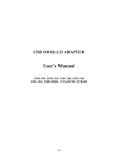
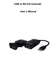
USB/RS-232 INTERFACE CONVERTER PD12 TYPE USERS MANUAL USB/RS-232 INTERFACE CONVERTER PD12 TYPE USERS MANUAL CONTENTS 1. APPLICATION ................................................................................ 5 2. CONVERTER SET ......................................................................... 5 3. CONVERTER INSTALLATION ...................................................... 6 3.1. Converter mounting ............................................................... 6 3.2. Description of converter leads .............................................. 6 3.3. Installation of the COM port for Windows ............................. 7 3.4. Installation of COM port controllers on the computer ........... 7 3.5. Example of Lumel-Heat and Lumel-Energy configuration to co-operate with PD12 ........................................................ 8 4. NOTES ........................................................................................... 8 5. TECHNICAL DATA ......................................................................... 9 6. ORDERING CODES ................................................................... 10 7. MAINTENANCE AND WARRANTY ............................................. 11 ! " 1. APPLICATION At present, more and more PC computers operating in industrial computer-based systems are equipped only with a USB (Universal Serial Bus) serial interface. This interface serves to communicate with other computers and devices in the framework of the USB network. The PD12 converter is a device enabling, in a very easy way, to create the connection between the USB and the RS-232 port , ensuring simultaneously between them the galvanic separation. The USB interface is destined to communicate with the computer, however the RS-232 interface is destined to communicate with devices in the object side. The maximal baud rate is 921.6 kb/s. The converter does not interfere in the structure of transmitted data and is compatible with a lot of industrial communication protocols, i.e. MODBUS RTU, MODBUS ASCII, LUMBUS, and the like. A programmed controller of the network serial port for the master system computer is added to the set. It allows supervising programs to exchange data with industrial objects via the PD12 converter. 2. CONVERTER SET The PD12 converter set includes: - PD12 converter - Users manual - Warranty card - Diskette with VCP drivers - Plate with controllers 1 1 1 1 1 pc pc pc pc pc When unpacking the converter, please check the delivery completeness and whether the type and version code on the data plate correspond to the order. # 3. CONVERTER INSTALLATION 3.1. Converter mounting The converter is a portable device supplied from z USB bus. The PD12 converter connection way is presented on the fig.1. RS-232 TxD RxD USB To RS-232 42,7 80,2 To USB Fig.1 Overall dimensions of the PD12 converter 3.2. Description of converter leads Markings of individual leads are shown on the fig. 2 USB TxD RxD USB RS-232 RS-232 Fig. 2 Leads of the PD12 converter External signals must be connected acc. to tables 1 and 2, in which the assignment of individual PD12 converter leads are described. There are two diodes on the frontal plate : Green (RxD) - signals the reception of data via RS-232 Yellow (TxD) - signals the transmission of data via RS-232 $ RS-232 interface leads DB9 RS-232 pin No 2 3 5 7 8 Table 1 RS-232 signals RxD TxD GND RTS CTS USB interface leads No of USB pin ( type B) 1 2 3 4 Table 2 USB signals +5 V d.c. -Data +Data GND 3.3. Installation of the COM port for Windows The PD12 converter unfair advantage of FTDIBUS and FTDIPORT driver controllers, licensed by Future Technology Devices International Ltd. This software creates a new device of the Universal Serial Bus system - USB RS232 converter of PD12 type and connected Port (Com) to it - PD12 USB-RS232 Port(COM). The installation of a controller in the Windows system causes the addition of the next COM serial port to the list of ports serviced by the operating system. 3.4. Installation of COM port controllers on the computer After connecting the converter to the USB port, the operating system will inform us about the occurrence of a new device by means of the system. The creator, finding the new hardware of the Universal Serial Bus will be started automatically. One must proceed acc. to the creator suggestions, choosing the Installation from the indicated location and giving the access path to controllers being on the plate added to the converter. On the plate with controllers, there are controllers for following operating systems: Windows 98, 98SE, 2000, ME and XP. When installing controllers, information that the software has not been submitted to tests in accordance with the Windows system % can occur. One must ignore such information and continue the further installation. After closing the creator, the system detects immediately the next device - USB Serial Port. The creator to find a new hardware will be started again. After the successful installation termination, the system will inform about the installation of a new hardware. Two new devices will appear in the device Manager - The USB-RS232 converter of PD12 type and PD12 USB-RS232 Port (COM). 3.5. Example of Lumel Heat and Lumel 3000 configuration to co-operate wit PD12 Lumel-Heat and Lumel 3000 systems communicate with industrial devices by means of COM serial ports. After installing additional COM serial ports, one can refer to them in systems of LUMEL series. Then, one must introduce in new and existing applications or system configurations, or change supervision cancellations to added communication ports. Lumel-Energy programs in older version than 2.5, service maximally 4 serial ports and in such systems, serial ports must be installed as COM1...4). 4. NOTES The PD12 converter can work with a maximal baud rate up to 921.6 kb/s on lines to 15 m length. ! & In the environment with unknown interference level it is recommended to observe following principles: l Connections of communication interface circuits must be conduct individually by twisted wires in a shield. l Apply the general principle that wires (group of wires) leading different signals should be led in the possible farthest distance between them (not less than 50 cm) and the crossing of such group of wires should be made at right angle. 5. TECHNICAL DATA USB: - compatible with - connector USB 1.0, 1.1, 2.0 USB type B RS-232: - Signals - Connector TxD, RxD, RTS, CTS, GND DB9 male Transmission data: - baud rate [kbit/s] - control of transmission flow - parity - data bits - stop bits - controllers 1.2... 921.6 RTS/CTS, XON/XOFF, WITHOUT CONTROL none, Even, Odd, Space, Mark 5, 6, 7, 8 1, 1.5, 2 Windows 98/98SE/Me, 2000/XP Converter power consumption 30 mA, at 5 V d.c. Rated operation conditions: - supply voltage - ambient temperature - relative humidity - external magnetic field - working position 5 V d.c., from the USB port 0... 55°C < 85% < 400 A/m any Storage and transport conditions: - ambient temperature - relative humidity - admissible sinusoidal vibrations: - frequency - displacement amplitude 10...150 Hz £ 0.35 mm Ensured protection grades: - from the housing side - from the terminal side Dimensions IP 40 IP 20 65 x 43 x 24 mm Weight 0.1 kg Housing portable 0...70°C < 85% ' Electromagnetic compatibility: - immunity - emission EN 61000-6-2 EN 61000-6-4 Safety requirements acc. EN 61010-1: - installation category III - pollution grade 2 Maximal working voltage in relation to earth: - for supplying circuits 50 V - for other circuits 50 V 6. ORDERING CODES PD12 version codes CONVERTER PD12 Table 4 X X X Galvanic insulation: with insulation ........................................................... 1 without insulation ...................................................... 2 Kind of version: catalog ............................................................................... 0 custom-made* ................................................................... X Acceptance tests: without extra requirements ......................................................... 0 with an extra quality inspection certificate ................................. 1 other requirements* .................................................................... X * The version code is established by the manufacturer Example of ordering: PD12 1 0 1 code means: PD12 - USB-RS485 interface converter: 1 - with galvanic insulation 0 - catalog version 1 - with an extra quality inspection certificate 7. MAINTENANCE AND WARRANTY The PD12 converter does not require any periodical maintenance. In case of some incorrect operations: 1. After the dispatch date and within the period stated in the warranty card One should return the instrument to the manufacturers Quality Inspection Dept. If the instrument has been used in compliance with the instructions, the manufacturer warrants to repair it free of charge. The disassembling of the housing causes the cancellation of the granted warranty. 2. After the warranty period One should send the instrument to repair it in an authorized service workshop. Spare parts are available for the period of five years from the date of purchase. Our policy is one of continuous improvement and we reserve the right to make changes in design and specifications of any products as engineering advances or necessity requires and revise the above specifications without notice. SALES PROGRAM § DIGITAL and BARGRAPH PANEL METERS § MEASURING TRANSDUCERS § ANALOG PANEL METERS (DIN INSTRUMENTS) § ANALOG and DIGITAL CLAMP-ON METERS § INDUSTRIAL and HOUSEHOLD CONTROLLERS § CHART AND PAPERLESS RECORDERS § POWER CONTROL UNITS and INVERTERS § AUTOMOTIVE DASHBOARD INDICATORS § ACCESSORIES FOR MEASURING INSTRUMENTS § MEASURING SYSTEMS (ENERGY, HEAT, CONTROL) § CUSTOM-MADE PRODUCTS MEASUREMENT CONTROL RECORDING WE ALSO OFFER OUR SERVICES IN THE PRODUCTION OF: § ALUMINIUM ALLOY PRESSURE CASTINGS § PRECISION ENGINEERING AND THERMOPLASTICS PARTS QUALITY PROCEDURES: According to ISO 9001 and ISO 14001 international requirements. All our instruments have CE mark . For more information, please write to or phone our Export Department Tel.: (48-68) 3295 100 (exchange) Fax: (48-68) 3295 101 e-mail:[email protected] http://www.lumel.com.pl Export Department: Tel.: (48-68) 3295 302 or 304 Fax: (48-68) 3254 091 e-mail: [email protected] )KCKIJ # Lubuskie Zak³ady Aparatów Elektrycznych LUMEL S.A. ul. Sulechowska 1, 65-022 Zielona Góra, Poland


