1
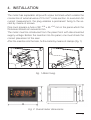
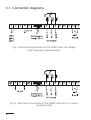
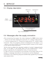
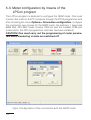
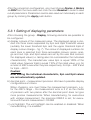
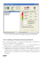
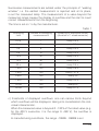
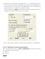
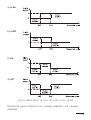
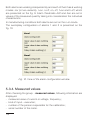
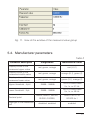
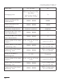
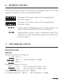
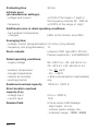
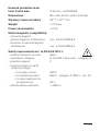
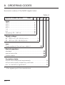
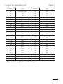
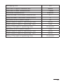
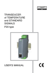
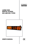
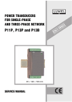
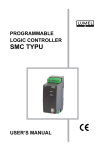
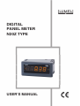
DIGITAL PANEL METER N20Z TYPE USER’S MANUAL 1 Contents 1. APPLICATION and METER DESIGN............................................ 5 2. METER SET....................................................................... 5 3. BASIC REQUIREMENTS, OPERATIONAL SAFETY........................... 6 4. INSTALLATION................................................................... 7 5. SERVICE........................................................................... 9 6. ERROR CODES.................................................................. 19 7. TECHNICAL DATA............................................................... 19 8. ORDER CODES.................................................................. 22 9. MAINTENANCE and GUARANTEE............................................. 26 1. APPLICATION and METER DESIGN The N20Z meter is a digital programmable panel instrument destined for measurements of a.c. voltages, a.c. currents, or frequency. The readout display is a LED display which enables the exposition of results in red, green or orange colour. The LPCon program is destined for the configuration of the N20Z meter. The meter must be connected with the PC computer through a PD14 converter. Parameters which can be reprogrammed are as follows: - display colour, individually in three intervals, - thresholds of displayed overflows, - display precision of the result (decimal point), - highlight of the unit, - kind of the measured signal a.c. or a.c. + d.c. (True RMS), - averaging time of the measurement, - recounting of indications (individual characteristic), - two alarms of OC type operating in six working modes. The switching of the output alarm on is signaled by the highlight of the triangular alarm index, at the left side of the display for the suitable alarm digit The highlight colour is always different from the colour of the displayed (measured) value. The protection level from the frontal side is IP 65. Meter overall dimensions: 96 ´ 48 ´ 64 mm (including terminals). 2. METER SET The set is composed of: - N20Z meter.......................................... 1 pc - User’s manual...................................... 1 pc - Guarantee card.................................... 1 pc - Clamps to fix in the panel.................... 4 pcs - Seal...................................................... 1 pc - Set of labels with units......................... 1 pc When unpacking the meter, please check whether the type and execution code on the data plate correspond to the order. 3. BASIC REQUIREMENTS, OPERATIONAL SAFETY In the safety service scope, the meter meets the requirements of the EN 61010-1 standard. Observations concerning the operational safety: · · · · · · · · All operations concerning transport, installation, and commissioning as well as maintenance, must be carried out by qualified, skilled personnel, and national regulations for the prevention of accidents must be observed. Before switching the meter on, one must check the correctness of connections to the network. Do not connect the meter to the network through an autotransformer. Before removing the meter housing, one must switch the supply off and disconnect measuring circuits. The removal of the meter housing during the guarantee contract period may cause its cancellation. The meter fulfills requirements related to electromagnetic compatibility in the industrial environment When connecting the supply, one must remember that a switch or a circuit-breaker should be installed in the building. This switch should be located near the device, easy accessible by the operator, and suitably marked as an element switching the meter off. Non-authorized removal of the housing, inappropriate use, incorrect installation or operation, creates the risk of injury to personnel or meter damage. For more detailed information, please study the User’s Manual. 4. INSTALLATION The meter has separable strips with screw terminals which enable the connection of external wires of 2.5 mm 2 cross-section. In execution for current measurement, the plug enables a permanent fixing to the socket by means of screws. One must prepare a hole of 92 +0.6 x 45 +0.6 mm in the panel which the thickness should not exceed 6 mm. The meter must be introduced from the panel front with disconnected supply voltage. Before the insertion into the panel, one must check the correct placement of the seal. After the insertion into the hole, fix the meter by means of clamps (fig. 1). Fig. 1 Meter fixing. Fig. 2 Overall meter dimensions 4.1. Connection diagrams Fig. 3 Electrical connections of the N20Z meter for voltage and frequency measurements Fig. 4 Electrical connections of the N20Z meter for a.c. current measurements 5. SERVICE 5.1. Display description Measured value Highlighted unit Alarm indexes Index displaying the current value Fig. 5 frontal panel 5.2. Messages after the supply connection After connecting the supply, the meter displays the N20ZL meter name – where L is the letter marking the execution: U – voltage measurement, I – current measurement, F – frequency measurement, S – custom-made execution. Next, the program version is displayed in the shape r x.xx – where x.xx is the number of the actual program version or the number of the custom-made execution. Till the time to obtain the required number of correct measurements (acc. to the table 1), the actual value from the measurement 1 is displayed, signaled by the highlighted index of the actual value. In case of an error occurrence or an overflow of the range value on the display, a message described in the section 6, will be displayed. Overflows of the measuring range are additionally signaled by the actual value signal index. 5.3. Meter configuration by means of the LPCon program The LPCon program is destined to configure the N20Z meter. One must connect the meter to the PC computer through the PD14 programmer and after choosing the menu Options-> Connection configuration, configure the connection (we choose for the N20Z meter, the address 1, baud rate 9600 kb/s, RTU 8N2 mode, timeout 1000 ms and the suitable COM port under which the PD14 programmer controller has been installed). CAUTION! One must carry out the programming of meter parameters when measuring circuits are switched off! Fig.6. Configuration of the connection with the N20Z meter 10 After the connection configuration, one must choose Device Meters N20Z from the menu and next click the icon Readout in order to read out all parameters. Parameters can be also read out individually in each group by clicking the Apply push-button. 5.3.1 Setting of displaying parameters After choosing the group: - Display, following elements are possible to be configured: a) display colours of the measured value. The displayed range is divided into three zones separated by KpL and KpH threshold values (suitably the lower threshold KpL and the upper threshold KpH of display colour change – fig. 7). The colour of displayed numbers for each zone is selected from three accessible colours: green, orange and red. KpL and KpH values are set by the user and concern the displayed value (i.e. taking also into consideration the individual characteristic). The manufacturer value KpL is equal 100% of the rated value, however KpH is equal 110% of the rated value, e.g. for a meter of 400 V execution they are respectively: for KpL – 400 V and for KpH – 440 V. Caution! After setting the individual characteristic, KpL and KpH values are not automatically updated. b) decimal point – measurement precision. We have 5 possible display configurations at choice. When choosing, one must follow the measurement precision, e.g.: for the 400 V range – the measurement error is 2 V, so the choice of precision with two places after the decimal point does not give more precise measurements. When manufacturing, for executions with voltage measurement, the precision 0000.0 is set; for executions with current measurement - 00.000 c) unit highlight. The unit highlight can be enabled or disabled. When manufacturing, it is enabled. 11 Fig. 7. View of the window of display parameter configuration 5.3.2. Setting of measurement parameters After choosing the group: - measurement parameters, following elements are possible for the configuration: a) kind of input: a.c. measurement, a.c. + d.c. measurement (True RMS), the a.c. measurement is set by the manufacturer. b) averaging time: till the time to obtain the required number of correct measurements (according to the table 1), the actual value from 1 measurement is displayed. After measuring a definite number of measurements, the arithmetic mean of measured measurements is displayed. 12 Successive measurements are added under the principle of “walking window”, i.e. the earliest measurement is rejected and at its place, is set the measured lately. The measurement of a value beyond the measuring range causes the display of overflow and the start to count correct measurements from the beginning. The time is set on 1 s by the manufacturer. Table 1 Averaging time Number of averaging measurements Updating of displayed values (duration of 1 measurements) 0.5 s 1 every 0.5 s 1 s 2 every 0.5 s 3 s 6 every 0.5 s 5 s 10 every 0.5 s 10 s 20 every 0.5 s 15 s 30 every 0.5 s 30 s 60 every 0.5 s 1 min 100 every 0.6 s 2 min 100 every 1.21 s 5 min 100 every 3 s 7 min 100 every 4.2 s 12 min 100 every 6 s 15 min 100 every 9.1 s c) thresholds of displayed overflows: one can narrow limits beyond which overflows will be displayed, taking into consideration the individual characteristic. When the measured value is beyond 0...120% of the rated value (e.g. for the 400 V execution, it is the range 0...480 V), the overflow is displayed. In manufacturing conditions, the range –19999... 99999 is set. 13 d) switching the individual characteristic on. In manufacturing conditions the characteristic is disabled. An example of configuration is given below for e.g. operation of the N20Z meter when choosing the kilovolt unit (kV) – the result is divided by 1000. After pressing the Apply push button, parameters a and b of the straight line equation are written on the meter. Fig. 8 View of the window of measurement parameter configuration. 5.3.3. Setting of alarm parameters After choosing the group: - alarm configuration, following elements are possible to be configured: a) alarm 1, b) alarm 2, 14 a) n-on b) n-off c) on d) off Fig. 9. Alarm types: a) n-on, b) n-off, c) on, d) off. Remaining types of alarms: h-on – always enabled; h-off – always disabled. 15 Both alarms are working independently and each of them has 6 working modes: nor (in two variants), n-on, n-off, on, off, h-on and h-off, which are presented on the fig. 9. Alarm thresholds Aoff and Aon are set in values of the measured quantity taking into consideration the individual characteristic. In manufacturing conditions both alarms are set on the n-on mode. The exemplary configuration of alarms 1 and 2 is presented on the fig. 10. Fig. 10. View of the alarm configuration window 5.3.4. Measured values After choosing the group: - measured values, following information are displayed: - measured value of current or voltage, frequency; - kind of input – execution; - number of the person responsible for the calibration; - serial number of the meter. 16 Fig. 11. View of the window of the measured value group 5.4. Manufacturer parameters Table 2 Parameter description Range/value Manufacturer value Display colour of the measured upper value red, green, orange red (U,I,f) Display colour of the measured middle value red, green, orange orange (U,I), green (f) Display colour of the measured lower value red, green, orange green (U,I), orange (f) Upper threshold - KpH -19999... 99999 110% of rated value Un, In, or 51 Hz Lower threshold - KpL -19999... 99999 100% of rated value Un, In, or 49 Hz 00000, 0000.0, 000.00, 00.000, 0.00000, 0000.0 for U,f or 00.000 for I disabled, enabled enabled Decimal point Highlight of the measured unit 17 (continuation) Table 2 Input type AC, AC+DC AC 0.5 s, 1 s, 3 s, 5 s, 10 s, 15 s, 30 s, 1 min, 2 min, 5 min, 7 min, 12 min, 15 min 1s Upper overflow of the measurement -19999... 99999 99999 Lower overflow of the measurement -19999... 99999 -19999 disabled, enabled, disabled Parameter a of the individual characteristic -19999... 99999 1 Parameter b of the individual characteristic -19999... 99999 0 Action mode of the alarm output 1 n-on, n-off, on, off, h-on, h-off n-on (U,I), off (f) Upper value of the alarm 1 switching - Aon -19999... 99999 110% of rated value Un, In, or 51 Hz Lower value of the alarm 1 switching - Aoff -19999... 99999 100% of rated value Un, In, or 49 Hz 0...120 0 second Action mode of the alarm output 2 n-on, n-off, on, off, h-on, h-off n-on (U,I), off (f) Upper value of the alarm 2 switching - Aon -19999... 99999 110% of rated value Un, In, or 51 Hz Lower value of the alarm 2 switching - Aoff -19999... 99999 100% of rated value Un, In, or 49 Hz Averaging time Individual characteristic Delay of the alarm 1 switching time 18 6. ERROR CODES After connecting the meter to the network, messages about errors may appears. Causes of errors are presented below: Overflow of the upper value of the programmed indication range. Overflow of the lower value of the programmed indication range. ErrCA Loss of meter calibration values – In such a case, one must contact an authorized service workshop. ErrEE Inappropriate values in meter configuration data. One must set up meter parameters again by means of the LPCon program 7. TECHNICAL DATA Measuring range INPUTS: Measuring range of voltage Un: 1...100...120 V 2.5... 250...300 V input resistance > 2 M 4... 400...480 V Measuring range of current In: 0.01... 1...1,2 A input resistance 50 m 10% 0.05... 5...6 A input resistance 10 m 10% Frequency measusurement: 20... 500 Hz (in voltage range 24... 480 V) input resistance > 2 M 19 Preheating time Intrinsic error (at manufacturer settings): - voltage and current - frequency 30 min. (0.5% of the range ±1 digit) in the frequency interval 20... 500 Hz (0.02% of the range ±1 digit) Additional errors in rated operating conditions: - from ambient temperature changes (50% of the intrinsic error/10K) Averaging time: - voltage, current (programmable) min 0.5s (1s by default) - frequency (not programmable) 1s Alarm outputs Rated operating conditions: outputs of O/C type (30 V, 20 mA), Passive outputs acc. to EN 62053-31 - supply voltage 85...253 V a.c. (45...65 Hz) or d.c. 20...40 V a.c. (45...65 Hz) or d.c. - ambient temperature - storage temperature - relative air humidity - working position - 10...23...55C - 25... + 85C < 95% (condensation inadmissible) any Sustained overload capacity 120% Un, 120% In Short duration overload capacity (3 s): - voltage input - current input 2 Un (< 1000 V) 10 In Readout field 5 three-colour LED displays: - digit height: 14 mm, - colours: green, orange, red, - indication range: -19999...99999 20 Ensured protection level from frontal side IP 65 acc. to EN 60529 Dimensions 96 48 64 mm (with terminals) Wymiary otworu w tablicy 92+0.6 45+0.6 mm Weight < 0.25 kg Power consumption < 6 VA Electromagnetic compatibility: – immunity against electromagnetic interference – emission of electromagnetic interference acc. to EN 61000-6-2 acc. to EN 61000-6-4 Safety requirements acc. to PN-EN 61010-1: – isolation between circuits basic – installation category III (for 400 V execution - category II) – pollution degree 2 – maximal phase-to-earth working voltage: – for supply circuit 300 V – for measuring input 600 V - category II (300 V - cat. III) – for input destined for programming 50 V – altitude above sea level < 2000 m 21 8. ORDERING CODES Execution codes of the N20Z digital meter Table 3 DIGITAL PANEL METER N20Z - X X XX XX X Input: 100 V ...........................................................1 250 V ...........................................................2 400 V ...........................................................3 1 A ...............................................................4 5 A ...............................................................5 frequency 20... 500 Hz . ..............................6 Supply voltage: 85... 253 V a.c. (45...65 Hz) or d.c. .................... 1 20... 40 V a.c. (45...65 Hz) or d.c. ...................... 2 Unit: Code number of the unit acc. table 4 ..................... XX Kind of execution: standard ......................................................................... 00 special execution ........................................................... XX custom-made ................................................................. 99 Acceptance tests: without extra additional requirements .....................................8 with an extra quality inspection certificate ..............................7 acc. to customer’s agreement* ...............................................X * - After agreeing with the manufacturer 22 Code of the highlighted unit Table 4 Code Unit Code Unit 00 01 02 03 04 05 06 07 08 09 10 11 12 13 14 15 16 17 18 19 20 21 22 23 without unit V A mV kV MA mA kA MA C F K Hz kHz Ah kAh m/s m mm cm m km l l/s 24 25 26 27 28 29 30 31 32 33 34 35 36 37 38 39 40 41 42 43 44 45 46 XX l/h ms s h N kN Pa hPa kPa MPa bar rad k % rev. rps rpm rph m/h km/h imp on order1) 1) After agreeing with the manufacturer 23 Ordering examples: Example 1: The code: N20Z - 3 1 01 00 8 means: N20Z – panel digital meter, 3 – with a 400 V a.c. input, 1 – supply voltage: 85... 253 a.c. (45... 65 Hz) or d.c. 01 – displayed unit: V 00 – standard execution, 8 – without an extra quality inspection certificate, Example 2: The code: N20Z - 3 2 04 99 8 (+ description) means: N20Z – panel digital meter, 3 – with a 400 V a.c. input, 2 – supply voltage: 20... 40 a.c. (45... 65 Hz) or d.c., 04 – displayed unit: kV, 99 – custom-made execution, with the description like in the table 5 (below), 8 – without an extra quality inspection certificate. Table 5 Parameter Colour of displayed measured upper value Colour of displayed measured middle value Colour of displayed measured lower value Upper threshold - KpH Lower threshold - KpL Decimal point Highlight of measured value Input type 24 Range/value red green orange 44.00 40.00 000.00 enabled AC Averaging time Overflow of upper measurement Overflow of lower measurement Individual characteristic Parameter a of individual characteristic Parameter b of individual characteristic Operation kind of alarm output 1 Upper value of alarm 1 switching - Aon Lower value of alarm 1 switching - Aoff Delay of the alarm 1 switching time Operation kind of alarm output 2 Upper value of alarm 2 switching - Aon Lower value of alarm 2 switching - Aoff Delay of the alarm 2 switching time 5s 99999 - 19999 enabled 0.1 0 on 40.00 0.00 0 second n-on 44.00 40.00 0 second 25 9. MAINTENANCE AND GUARANTEE The N20Z digital panel meter does not require any periodical maintenance. In case of some incorrect operations: 1. In the period of 12 months from the date of purchase: One should take the meter down from the installation and return it to the Manufacturer’s Quality Control Dept. If the unit has been used in compliance with the instructions, the Manufacturer warrants to repair it free of charge. 2. After the guarantee period: One should turn over the meter to repair it in a certified service workshop. The disassembling of the housing causes the cancellation of the granted guarantee. Our policy is one of continuous improvement and we reserve the right to make changes in design and specifications of any products as engineering advances or necessity requires and revise the above specifications without notice. 26 27 Lubuskie Zak³ady Aparatów Elektrycznych LUMEL S.A. ul. Sulechowska 1, 65-022 Zielona Góra, Poland Export Department: Tel.: (48-68) 329 53 02 Fax: (48-68) 325 40 91 e-mail: [email protected] 28 N20Z-07 Tel.: (48-68) 329 51 00 (exchange) Fax: (48-68) 329 51 01 e-mail:[email protected] http://www.lumel.com.pl