1
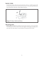
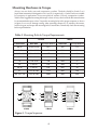
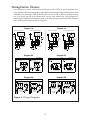
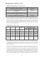
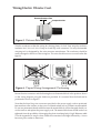
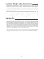
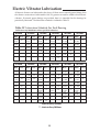
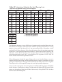
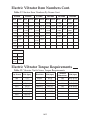
Italvibras USA
Industrial Electric Vibrators
Model MVSI
Operator’s Manual
Table of Contents
Section Title
Page
Tables and Figures Index . . . . . . . . . . . . . . . . . . . . . . . . . . . . . . . . .Below
Introduction . . . . . . . . . . . . . . . . . . . . . . . . . . . . . . . . . . . . . . . . . . . . . . . . .1
Installation Design Tips . . . . . . . . . . . . . . . . . . . . . . . . . . . . . . . . . . . . . . .2
Force Output Adjustment . . . . . . . . . . . . . . . . . . . . . . . . . . . . . . . . . . . .11
Lubrication requirements . . . . . . . . . . . . . . . . . . . . . . . . . . . . . . . . . . . .13
Electric Vibrator Repair & Maintenance . . . . . . . . . . . . . . . . . . . . . . . .15
Appendix
Electric Vibrator Item Numbers . . . . . . . . . . . . . . . . . . . . . . . . . . . . . .A1
Electric Vibrator Torque Requirements . . . . . . . . . . . . . . . . . . . . . . . .A2
Electric Vibrator Dimensions . . . . . . . . . . . . . . . . . . . . . . . . . . . . . . . . .A3
Electric Vibrator Parts List Diagrams . . . . . . . . . . . . . . . . . . . . . . . .A4-6
Figures
Figure #
Page
1
2
3
4
5
6
7
8
9
10
11
Electric Vibrator Mounting Examples . . . . . . . . . . . . . . . . . . . . . . .2
Safety Cable Installation . . . . . . . . . . . . . . . . . . . . . . . . . . . . . . . . . .3
Mounting Bolt Torque Sequence . . . . . . . . . . . . . . . . . . . . . . . . . . .4
Wiring Diagrams . . . . . . . . . . . . . . . . . . . . . . . . . . . . . . . . . . . . . . . . .5
Distance Between Flats . . . . . . . . . . . . . . . . . . . . . . . . . . . . . . . . . . .7
Proper Wiring Arrangement/Positioning . . . . . . . . . . . . . . . . . . . .7
Terminal Block Hardware Installation . . . . . . . . . . . . . . . . . . . . . .8
Wiring Block Assembly . . . . . . . . . . . . . . . . . . . . . . . . . . . . . . . . . . .8
Ground Bonding Screw . . . . . . . . . . . . . . . . . . . . . . . . . . . . . . . . . .10
Eccentric Weight Adjust . . . . . . . . . . . . . . . . . . . . . . . . . . . . . . . . . .11
Setting Sets of Eccentric Weights to Mirror Images . . . . . . . . . .11
I
II
III
IV
V
VI
VII
Mounting Bolt & Torque Requirements . . . . . . . . . . . . . . . . . . . . .4
Wiring Diagram Identification . . . . . . . . . . . . . . . . . . . . . . . . . . . . .6
Cord Grip Chart . . . . . . . . . . . . . . . . . . . . . . . . . . . . . . . . . . . . . . . . . .6
Lubrication Schedule for Each Bearing . . . . . . . . . . . . . . . . . .13-14
Vibrator Item Number By Frame . . . . . . . . . . . . . . . . . . . . . . . .A1-2
Vibrator Nut & Screw Torque Requirements . . . . . . . . . . . . . . .A2
Vibrator Dimensions By Frame . . . . . . . . . . . . . . . . . . . . . . . . . . .A2
Tables
Table
Page
© 2011 Italvibras USA
All rights reserved.
All materials subject to change.
3/11
Introduction
Italvibras USA industrial electric vibrators have been designed and manufactured in accordance
with the most exacting international industrial standards and requirements. Italvibras USA
industrial electric vibrators are designed for long life at continuous duty and maximum force
output. The electric vibrators are suitable for operation in ambient from -30°C to 40°C (operation
outside of this range needs engineering consideration).
Italvibras USA industrial electric vibrators have been evaluated for installation throughout the
world. Standard ratings include CSA (Canadian Standards Association) Approval, the CE
(European Directive) Mark, EX Approval for Zone 21 (ATEX II2D tD A21 IP66), Russian GOST
Mark and IECEx Approval (II2D tD A21 IP66). Check the electric vibrator nameplate for the
exact ratings and Approvals for the specific Model.
The electric vibrator can be referred to by its Model or Type designation or by its Item number.
The vibrator Model or Type designations referred to in this manual are as follows:
MVSI – Continuous duty industrial electric vibrator, single or three phase.
The electric vibrator may optionally be CSA Approved for Class I, Division 2, Group A, B, C and
D hazardous locations, or it may be marked as being suitable for Class II, Division 2, Group F
and G hazardous locations. Applications and installations requiring Division 1 equipment shall
use Italvibras’ CDX explosion-proof and dust-ignition-proof industrial electric vibrators.
General Safety requirements
Read this entire manual before proceeding. Compliance with all company, local and
OSHA regulations is essential. Any electrical work must be done in accordance with all
applicable local and national codes and must be performed only by qualified, licensed and
authorized personnel. Always follow lockout and tag out procedures and requirements and
always wear ear protection when in close proximity to operating vibratory equipment.
Comprehensive adherence to these documents at a minimum is required – The National
Electrical Code NFPA 70, ANSI z244.1 the American National Standard for Personnel Protection
– Lockout/Tag out of Energy Sources – Minimum Safety Requirements, CFR 29 Part 1910 –
Control of Hazardous Energy Sources (Lockout/Tag out) Final Rule and CFR 29 Part 1910.15
Occupational Noise Exposure.
Storage
Storage of the electric vibrator should be in an ambient not less than 5°C with a relative
humidity not more than 60%. If the vibrator has been stored for longer than two years, the
vibrator should be evaluated by authorized and trained personnel to ensure that the grease is
intact, that there is no bearing damage such as brinelling and that the ground insulation is
sound and not damaged from condensation.
1
Installation
Before installing the vibrator, make sure that you have everything that you will need and that
there is no shipping damage. Any product damage should be reported to the delivery service
immediately. Standard metric hand tools will be needed. Carefully handle the electric vibrator.
Dropping or impacting the electric vibrator may damage the bearings.
Welding – Never weld on a bin, hopper or machine with the electric vibrator mounted to it
since the welding may damage the vibrator bearings or electrical circuits. When you do weld,
especially in an enclosed area, make sure that the area is known to be nonhazardous and that
there are no flammable or explosive levels of gases, vapors or dusts.
Mounting Surface – The object of vibration on bins and hoppers is to transmit vibration energy
through the structure to the material within. The mounting surface must be rigid and strong for
this transfer of energy to take place. The mounting surface must also be clean, flat (0.010 in.
across mounting feet maximum), free of paint and have a minimum thickness equal to the
major diameter of the mounting bolt. Also make sure that the electric vibrator feet are clean
and free of debris.
Mounting Plate
The mounting plate should be at least the overall size of the electric vibrator feet. It should be
located on the bin and hopper wall at a height of ¼ to 1/3 of the sloped wall height. The
mounting plate or bracket should extend at least ¾ the length of the sloped wall. Reference
Figure 1. If a second electric vibrator is to be installed to the bin or hopper, install it at a height
of ½ of the sloped wall height and 180° from the first vibrator. Weld the mounting plate or
bracket to the structure wall with skip welds that are 3 in. long then skip 2 in. then 3 in. long
weld, etc. Do not weld at corners of mounting plate within 1 in. of the corner.
Figure 1. Mounting Examples
2
Safety Cable
Always install a safety cable metal rope from the electric vibrator to a reliable support should
the vibrator become free from its mount and fall more than 6 in. The metal rope should be taut
and positioned above the electric vibrator. Reference Figure 2.
6”
Figure 2. Safety Cable Installation
Mounting Kits
Mounting kits are available from Italvibras USA for frame sizes 00, 01, 10, 20, 30, 40 and 50.
The mounting kits include a channel mount with integral mounting plate, mounting screws
and washers and safety cable kit. Contact Italvibras USA by phone at 815-872-1350.
3
Mounting Hardware & Torque
Always use new bolts, nuts and compression washers. The bolts should be Grade 5 or 8
(equivalent international designation is 8.8 and 12.9, respectively). Grade 5 bolts are suitable
for a majority of applications. Do not use split lock washers. Use only compression washers.
Table I offers suggested mounting bolt torque values. Always check with the bolt manufacturer
for recommended torque values. Torque the mounting bolts in the proper sequence as shown
in figure 3 so as not to damage casting. After operating vibrator for 15 minutes, disconnect,
lockout/tag out, and torque the mounting bolts a second time. Periodically check the mounting
bolt torque thereafter.
Table I. Mounting Bolts & Torque Requirements
Frame Size
Bolt Size
British
Dry Torque Grade 5
Bolt Size
58
M12
288
M20
00, 01
5/16 in-18 NC
30, 33, 35 ,40, 50
5/8 in-11 NC
137
7/8 in -9 NC
430
10, 20
1/2 in-13 NC
60
3/4 in -10 NC
80
1 in-8 NC
70
90, 95
97
16.5
645
1 in-8 NC
100, 105, 110
4
2
3
4 Bolts
6
1
2
5
4
4
M16
19
M24
71
38
71
89
190
M42
3
Figure 3. Torque Sequence
8
M36
2090
6 Bolts
2.3
M27
1370
1-5/8 in-8 NC
Dry Torque Grade 8.8
M24
645
1-3/8 in-8 NC
1
M8
Metric
290
5
8
3
2
7
6
1
4
8 Bolts
Wiring Electric Vibrator
It is mandatory to comply with the National Electrical Code, NFPA 70, and all applicable local
codes. Identify which wiring diagram is applicable by referencing the Diagram designation on the
nameplate or by referring to Table II. Remove the four screws with washers securing the wiring
box cover along with the foam rubber block and set aside. Identify the wiring diagram by
referencing the predetermined Diagram noted on the wiring diagram found within the wiring box
or by referring to the Diagrams shown in Figure 4.
Diagram 1E
Diagram 1A
W2
U2
V2
U1
V1
W1
U1
V1
W1
cord
4-wire
W2
cord
4-wire
V1
V2
W2
W1
U1
3-wire cord
60 HZ
U2
V2
460 V
230 V
V1 W1
7
Ground
U1
1
8
9
2
3
3-phase
power supply
3-phase
power supply
Ground
6
Thermistor
W1
3-phase
power supply
To control
module
4
Thermistor
W2
U2
V2
7
U1
V1
W1
1
6
5
8
9
2
3
230 V
Thermistor
9
1
2
3
3-phase
power supply
To control
module
Figure 4. Wiring Diagrams
5
To control
module
DIAGRAM 5B
4
5
6
7
8
9
2
3
1
460 V
Thermistor
3-phase
power supply
3-phase
power supply
Ground
V1
6
8
60 HZ
High Voltage
Ground
Ground
U1
V2
5
7
Diagram 5B
DIAGRAM 5A
Low Voltage
4
3-phase
power supply
Ground
V1 W1
5
Ground
W2
V2
3-phase
power supply
U2
DIAGRAM 2C
High Voltage
U2
Diagram 5A
W2
power supply
115V, 60Hz
Diagram 2C
4
Ground
V2
W1
3-wire cord
DIAGRAM 2A
U1
Hot
power supply
115V, 60Hz
Diagram 2A
W2
V1
G L1 L2 T1 T2 T3
Neutral
Hot
power supply
115V, 60Hz
3-wire cord
Low Voltage
U2
cord
4-wire
G L1 L2 T1 T2 T3
Neutral
Hot
3-wire cord
Neutral
Hot
Neutral
power supply
115V, 60Hz
U1
U2
cord
4-wire
G L1 L2 T1 T2 T3
G L1 L2 T1 T2 T3
Rotation in opposite direction
Rotation in one direction
switch
box
V2
switch
box
U2
switch
box
Rotation in opposite direction
W2
switch
box
Rotation in one direction
To control
module
Wiring Electric Vibrator Cont.
Table II. Wiring Diagram Identification
00 through 01, single-phase, 3600 rpm
Diagram 1A
00 through 60, three-phase,1200,1800 & 3600 rpm; MVSI 9-590; &
575-volt 900 rpm
Diagram 2A
10 through 30, single phase, 3600 rpm
Diagram 1E
40 through 60, three-phase, 900 rpm except 575V
70 through 110, three-phase, 1200, 1800 & 3600 rpm; & 575V 900
rpm
70 through 110, three-phase, 900 rpm except 575V
Diagram 2C
Diagram 5A
Diagram 5B
Select a cord type that has a voltage rating not less than the power supply voltage, that has a
minimum temperature rating of 105°C, and that has an overall jacket diameter within the range
specified in Table III. This table also details the cord provided by the factory for reference. We
recommend Coleman black portable cord SEOOW Seoprene rated 600 V and 105°C. Coleman
Cable Inc. can be reached by phone at 847-672-2300 or at www.colemancable.com. Italvibras
USA also stocks the Coleman cable.
Table III. Cord Grip Chart
Frame Size
00, 01, 10
20-70
80-95
97-110
Thermistor
Circuit Cord
Size
mm x 1.5
Item No.
M25
511597
Suitable Cord
Diameter Range,
mm
M20
511596
M32
511598
13-21
511596
6.5-12
M32
M20
511598
6.5-12
9-16
13-21
Cord Provided By Factory
Size
Nominal
Diameter, in.
Distance Between
Flats, in.
14/4
0.575
1/16 to 1/8
8/4
0.807
3/32 to 5/32
0.39
1/16 to 1/8
16/4
10/4
16/3
0.42
0.705
1/16 to 1/8
1/16 to 1/8
When wiring the electric vibrator, leave enough slack in the cord so that the cord does not become
taut during operation causing stress on the connections. It is always best to position the cord down
so that should there be any moisture present the moisture would tend to run down instead of into
the vibrator wiring box.
Trim the cord by removing the jacket exposing the conductors and ground wire for approx. 6 in.
Be careful not to cut the conductor or ground wire insulation. Loosen the compression nut from
the cord fitting assembled to the side wall of the wiring box on the electric vibrator. Position the
compression nut on the cord and insert the cord through the opening in the side wall of the wiring
compartment. Position the jacket of the cord approx. ½ in beyond the inside wall of the wiring box
wall and secure the compression nut by threading it to a position equal to the “Distance Between
Flats” noted in Table III. Reference figure 5. which pictorially defines “Distance Between Flats”
6
Wiring Electric Vibrator Cont.
Distance Between Flats
Compression Nut
Figure 5. Distance Between Flats
Trim the conductors within the wiring box leaving plenty of slack. Next, strip the conductor
insulation for 1/4 in. to 3/8 in. Crimp on closed loop wire connectors. Use only the intended
crimping tool as designated by the wire connector manufacturer. The conductors should be
neatly arranged on the floor of the wiring box. The wires should not cross over each other. See
figure 6.
Figure 6. Proper Wiring Arrangement/Positioning
Secure the wire connectors and the shorting bars to the terminal block in the positions shown
on the wiring diagram using the hardware provided. It is essential that the hardware be
positioned as shown in Figure 7.
Note that the closed loop wire connectors provided on the power supply cord are positioned
between the two flat washers. A drop or two of thread sealant such as Locktite is recommended.
Do not use permanent thread sealant because the terminal block will be damaged should you
wish to remove and replace the power supply cord. The terminal block nuts should not be over
tightened since the possibility of damaging the plastic insulating body is high. Reference table
VI in the Appendix for torque values. Make the connections hand-tight followed by a ¼ turn
but never put a ratchet on these nuts.
7
Wiring Electric Vibrator Cont.
Figure 7. Terminal Block Hardware Installation
For wiring diagrams 1A, 1E, 2A and 2C (Fig.4), reinstall the rubber block over the power supply
conductors and install the wiring box cover being careful not to pinch the O-ring. Screw torque
is specified in the Appendix. See figure 8.
Figure 8. Wiring Block Assembly
For wiring diagrams 5A and 5B, you will note that there is a small 2-pole terminal block in the
wiring box. This is the thermistor circuit. Proceed to Thermistor Wiring.
8
Thermistor Wiring
Electric vibrators with Diagram 5A and 5B have thermistor circuits installed in the winding.
These devices are intended to protect the winding from over-temperature. Connect the
thermistors to the motor starter using a thermistor control module such as Siemens 3RN10121CK00. Never apply line voltage to the thermistor circuit. It is a low voltage +/- 5V dc circuit.
The thermistor control module is connected to the motor starter control circuit which commonly
operates at 120 Vac. Follow the wiring diagram provided with the thermistor control module.
The thermistors are our Item No. 0539503 and are rated 130°C. There are three PTC thermistors
wired in series that are installed in the vibrator winding and connected to blue or grey leads.
These leads are secured to the small 2-pole terminal block mounted in the wiring box.
To assemble the thermistor cord, remove the threaded metal plug assembled in the side wall of
the wiring box and install a M20 cord grip (our Item No. 0511596). Select a cord type that has
a voltage rating not less than the power supply voltage, that has a minimum temperature rating
of 105°C, and that has an overall jacket diameter within the range specified in Table III. This
table also details the cord provided by the factory for reference. We recommend Coleman black
portable cord SEOOW Seoprene rated 600 V and 105°C. Coleman Cable Inc. can be reached by
phone at 847-672-2300 or at www.colemancable.com. Italvibras USA also stocks the Coleman
cable.
Trim the cord by removing the jacket exposing the conductors for approx. 6 in. Be careful not
to cut the conductor wire insulation. Loosen the compression nut from the cord fitting
assembled to the side wall of the wiring box on the electric vibrator. Position the compression
nut on the cord and insert the cord through the opening in the side wall of the wiring
compartment. Position the jacket of the cord approx. ½ in beyond the inside wall of the wiring
box wall and secure the compression nut by threading it to a position equal to the “Distance
Between Flats” noted in Table III. Reference figure 5 which pictorially defines “Distance
Between Flats”.
Trim the conductors within the wiring box leaving plenty of slack. Next, strip the conductor
insulation for ¼ in. to 3/8 in. The conductors should be neatly arranged on the floor of the
wiring box. The wires should not cross over each other. Secure the wires to the 2-pole terminal
block by tightening the compression screws. Reinstall the rubber block over the power supply
and thermistor circuit conductors and install the wiring box cover being careful not to pinch the
O-ring. Screw torque is specified in the Appendix. Reference figure 8.
Grounding & Bonding
The electric vibrator must be grounded using the ground wire
provided in the cord. The ground wire shall be connected to a
closed loop wire connector which is then connected to the ground
terminal located within the wiring box (See figure 6). The ground
terminal is identified by the international symbol.
GROUND
It may be necessary to bond the electric vibrator to ground using the external ground screw
as shown in figure 9. The external ground terminal is identified by the international symbol.
Use a wire size no smaller than the internal ground wire.
9
Grounding & Bonding Cont.
Figure 9. Ground Bonding Screw
Overload, Short-Circuit & Ground-Fault Protection
In the USA, The National Electrical Code, NFPA 70, and all applicable local codes, govern how
to properly size, select and install overload protection (sometimes called heaters) and shortcircuit and ground-fault protection (fuses or circuit breakers). Proper selection and installation
of these devices is required and essential for not only protection of the electric vibrator and the
power supply circuit but also for protection of personnel.
If the overload or short-circuit and ground fault protection operate, have qualified personnel
locate and fix the problem before resetting.
When operating two electric vibrators, the vibrators should be controlled with a single motor
starter that has overload protection dedicated to each electric vibrator. The overloads shall be
electrically interlocked such that should there be a fault with one electric vibrator, both electric
vibrators will be de-energized.
Variable Frequency Inverter
The electric vibrators may be supplied with a variable frequency inverter. Never operate the
vibrators above the maximum frequency noted on the nameplate. If operating two vibrators,
use one variable frequency inverter along with overload protection dedicated to each electric
vibrator. The overloads shall be electrically interlocked such that should there be a fault with
one electric vibrator, both electric vibrators will be de-energized.
The nameplate current should never be exceeded throughout the entire frequency range.
10
Eccentric Weight Adjustment
The eccentric weights may be adjusted to produce the desired centrifugal force output. It is
always best to operate the electric vibrator at the lowest weight setting that produces the desired
result. This will result in lower energy expense and extend the bearing life. The factory setting
is 50% which would result in 50% of the centrifugal force noted on the nameplate. To adjust the
force output, lockout/tag out the electric vibrator. Remove each weight cover and set it and the
screws, washers and O-rings aside. The outer adjustable weight clamping screw or the shaft nut
may be loosened and then the adjustable weights may be rotated to the desired position.
Reference Figure 10.
Figure 10. Eccentric Weight Adjust.
The eccentric weights must be adjusted to mirror images of each other at the same setting
number as shown in Figure 11.
Figure 11. Setting Sets of Eccentric Weights to Mirror Images
Properly torque the clamping screw or shaft nut to secure the weights in position. Torque values
are outlined in the Appendix. Reinstall the weight covers making sure not to pinch the O-rings.
11
Eccentric Weight Adjustment Cont.
Check shaft rotation before replacing weight covers. Start vibrator for 1 second, stop and
lockout/tag out. Observe direction of rotation. If desired to reverse the direction of rotation,
switch two of the three power supply leads in the wiring box or at the motor starter for 3-phase
electric vibrators. For 1-phase electric vibrators, refer to the wiring diagram for changing the
direction of shaft rotation.
Replace weight covers using screws and washers being careful not to pinch the O-rings. The
screw torque is outlined in the Appendix. Never operate the electric vibrator without weight
covers in place. They provide a degree of protection for the bearings and a shield for the rotating
eccentric weights. Always replace broken weight covers immediately. Do not operate electric
vibrator with weight covers removed or with damaged weight covers.
Starting Up
After making sure that the power supply voltage matches the voltage marked on the nameplate,
that the mounting bolts are properly secured, that all covers are in place and secured, and that
the motor starter is properly installed and adjusted, turn the electric vibrator on. Excessive
noise would indicate a problem but slight bearing noise is normal due to the type of bearing
used. After a few hours of operation, check each line current and verify that it does not exceed
nameplate current. If the line current exceeds the nameplate current, then the mount needs to
stiffened, the vibrator weights need to be reduced or the vibrator needs to be moved to a more
rigid location. Never operate the vibrator above nameplate current.
After the first 8 hours of operation, check the line current to make sure that it does not exceed
nameplate and check mounting bolt torque. See MOUNTING HARDWARE AND TORQUE.
12
Electric Vibrator Lubrication
All electric vibrators are lubricated at the factory. If there are no external grease fittings, then
the vibrator construction is lubricated for life. No grease ever need be added to these electric
vibrators. If external grease fittings are provided, then it is intended that the bearings be
periodically lubricated. The lubrication schedule is outlined in Table IV.
Table IV. Lubrication Schedule For Each Bearing
Lubricate every 2000 hours unless specified otherwise.
00 Frame
01 Frame
10 Frame
20 Frame
30 Frame
33 Frame
Model
Grease, g
Model
Grease, g
Model
Grease, g
Model
Grease, g
Model
Grease, g
Model
Grease, g
MVSI
36-380
MVSI
18-100
Life
MVSI
36-480
MVSI
18-180
MVSI
18-250
Life
MVSI
36-660
MVSI
18-480
MVSI
12-110
MVSI
12-300
Life
MVSI
36-1050
MVSI
36-1500
MVSI
18-920
MVSI
18-1310
MVSI
12-580
MVSI
9-340
Life
MVSI
36-1680
MVSI
18-1690
MVSI
18-2280
MVSI
12-760
MVSI
9-590
Life
MVSI
36-2900
MVSI
36-3500
Life
Life
35 Frame
Life
Life
40 Frame
Life
Life
Life
50 Frame
Life
Life
Life
Life
Life
9
Life
Life
Life
Life
60 Frame
70 Frame
80 Frame
Model
Grease, g
Model
Grease, g
Model
Grease, g
Model
Grease, g
Model
Grease, g
Model
Grease, g
MVSI
36-2530
MVSI
18-2150
MVSI
12-1630
MVSI
12-1660
MVSI
9-910
MVSI
9-1160
7
MVSI
18-3190
MVSI
12-1990
MVSI
9-1440
9
MVSI
36-3280
MVSI
36-4080
MVSI
36-4100
MVSI
36-4910
MVSI
18-3870
MVSI
18-4500
MVSI
12-2540
MVSI
12-3110
MVSI
9-2030
9
MVSI
13-5380
MVSI
18-6850
MVSI
12-3410
MVSI
12-4700
MVSI
9-2920
MVSI
9-3850
19
MVSI
36-6860
MVSI
36-8240
MVSI
36-11000
MVSI
18-8300
MVSI
18-9420
MVSI
12-6050
MVSI
12-6600
MVSI
9-4640
26
MVSI
18-10900
MVSI
18-13400
MVSI
12-8450
MVSI
12-10400
MVSI
12-11400
MVSI
9-6830
MVSI
9-8400
40
7
Life
Life
Life
Life
Life
Life
Life
16
16
16
16
19
Life
Life
Life
Life
Life
Life
Life
* - Lubricate Every 750 Hours
** - Lubricate Every 200 Hours
13
26
30*
26
26
18
18
18
40
30
40
40
30
40
Table IV. Lubrication Schedule For Each Bearing Cont.
Lubricate every 2000 hours unless specified otherwise.
90 Frame
95 Frame
97 Frame
100 Frame
105 Frame
110 Frame
Model
Grease, g
Model
Grease, g
Model
Grease, g
Model
Grease, g
Model
Grease, g
Model
Grease, g
MVSI
36-14000
20**
MVSI
36-20000
25**
MVSI
18-19700
90
MVSI
18-25300
130
MVSI
12-31000
150
MVSI
12-45000
220
MVSI
18-14500
60
MVSI
18-17600
80
MVSI
12-14500
60
MVSI
18-32900
150
MVSI
12-37000
180
MVSI
12-55000
TBD
MVSI
12-11700
50
MVSI
12-17600
80
MVSI
12-20100
90
MVSI
12-26500
130
MVSI
12-40000
180
MVSI
9-49000
220
MVSI
12-12300
50
MVSI
12-19100
80
MVSI
12-24400
90
MVSI
9-24800
130
MVSI
9-31000
150
MVSI
9-57000
TBD
MVSI
12-14400
60
MVSI
9-14400
80
MVSI
12-29000
130
MVSI
9-38000
180
MVSI
12-15400
60
MVSI
9-14500
60
MVSI
9-9310
50
MVSI
9-21900
90
MVSI
9-11700
60
120 Frame
Model
Grease, g
MVSI
12-67000
MVSI
9-67100
260
* - Lubricate Every 750 Hours
** - Lubricate Every 200 Hours
260
The lubrication frequency is every 2000 hours of operation unless specified otherwise in the
table. There is an exception - 3600 rpm electric vibrators operating continuously or for long
periods of time should be lubricated in ½ the time specified using ½ the grease volume
specified. For all other vibrators, follow the table except when the operating temperature
exceeds 90°C. If the operating temperature exceeds 90°C, reduce the lubrication frequency and
lubrication volume by 50% for every 10°C increment above 90°C. If the electric vibrator
operating temperature exceeds 100°C, contact Italvibras USA by phone at 815-872-1350. The
electric vibrator should never operate above 120°C.
When adding grease through the grease fitting, make sure to clean the fitting so as not to
introduce dirt into the bearing. Add the specified amount of grease. Experiment with your
grease gun to determine how many grams are introduced with each pump. Never over-grease
a bearing since this will damage the bearing and cause high operating temperature.
Always use the correct grease. Never mix greases. Use Kluber NBU 15 grease in all MVSI 36
electric vibrators. All other electric vibrators are lubricated with Kluber NBU 8EP grease. Kluber
grease may be purchased direct from Kluber Lubrication by calling 800-447-2238. Italvibras
USA also stocks the Kluber grease.
14
Electric Vibrator Repair
If the electric vibrator needs repair, contact Italvibras USA at 815-872-1350 for instructions. Most
electric motor repair shops are not trained to repair our industrial electric vibrators. We
recommend that they be returned to the service center located in Princeton, IL. Attempting to
repair the electric vibrator or replace the bearings will void the warranty.
Electric Vibrator Maintenance
Every quarter, we recommend a thorough inspection of the electric vibrator. After lockout/tag
out, do the following:
1.) Inspect the cord for any visible damage or wear. Replace the cord if there are any
signs of damage or wear. This holds true for both the power supply cord and the
thermistor circuit cord.
2.) Remove the wiring box cover and inspect for any foreign matter or liquid.
Vacuum any foreign matter. If wet, remove electric vibrator from service and
have the ground insulation tested by a trained, qualified and licensed technician.
3.) Before replacing the wiring box cover, make sure the electrical connections are
tight (do not over-tighten) and inspect the cover O-ring and rubber compression
block. If the O-ring or rubber compression block is damaged or if they have lost
their compression set, replace them.
4.) Remove each weight cover and inspect for foreign matter. Vacuum if necessary.
Replace O-rings if they are damaged or if they have lost their compression set.
5.) Check the mounting bolt torque.
6.) Replace any broken parts.
15
Appendix
Electric Vibrator Item Numbers
The table below outlines a list of electric vibrator Model/Type designations next to their
respective Item No. The information is sorted by frame size. Please reference the Model/Type
designation and Item No. when ordering electric vibrators or their parts.
Table V. Vibrator Item Numbers By Frame
00 Frame
01 Frame
10 Frame
20 Frame
30 Frame
33 Frame
Model
Item No.
Model
Item No.
Model
Item No.
Model
Item No.
Model
Item No.
Model
Item No.
MVSI
36-380
MVSI
18-100
600311
MVSI
36-480
MVSI
18-180
MVSI
18-250
600312
MVSI
36-660
MVSI
18-480
MVSI
12-110
MVSI
12-300
600313
MVSI
36-1050
MVSI
36-1500
MVSI
18-920
MVSI
18-1310
MVSI
12-580
MVSI
9-340
600314
MVSI
36-1680
MVSI
18-1690
MVSI
18-2280
MVSI
12-760
MVSI
9-590
600381
MVSI
36-2900
MVSI
36-3500
600491
601340
35 Frame
601341
601366
40 Frame
601367
602296
602297
50 Frame
600366
601372
601373
602298
601408
600504
601513
602314
602575
602568
60 Frame
70 Frame
80 Frame
Model
Item No.
Model
Item No.
Model
Item No.
Model
Item No.
Model
Item No.
Model
Item No.
MVSI
36-2530
MVSI
18-2150
MVSI
12-1630
MVSI
12-1660
MVSI
9-910
MVSI
9-1160
600513
MVSI
18-3190
MVSI
12-1990
MVSI
9-1440
601217
MVSI
36-3280
MVSI
36-4080
MVSI
36-4100
MVSI
36-4910
MVSI
18-3870
MVSI
18-4500
MVSI
12-2540
MVSI
12-3110
MVSI
9-2030
600502
MVSI
13-5380
MVSI
18-6850
MVSI
12-3410
MVSI
12-4700
MVSI
9-2920
MVSI
9-3850
601220
MVSI
36-6860
MVSI
36-8240
MVSI
36-11000
MVSI
18-8300
MVSI
18-9420
MVSI
12-6050
MVSI
12-6600
MVSI
9-4640
600470
MVSI
18-10900
MVSI
18-13400
MVSI
12-8450
MVSI
12-10400
MVSI
12-11400
MVSI
9-6830
MVSI
9-8400
601211
601524
602402
602403
602615
602616
602380
602609
600503
600256
600257
601219
601267
602381
602382
602610
A-1
601268
602406
602407
602618
602619
600471
600472
601221
601269
602167
602230
602891
601447
602154
602204
602350
602884
602515
Electric Vibrator Item Numbers Cont.
Table V. Vibrator Item Numbers By Frame Cont.
90 Frame
95 Frame
97 Frame
100 Frame
105 Frame
110 Frame
Model
Item No.
Model
Item No.
Model
Item No.
Model
Item No.
Model
Item No.
Model
Item No.
MVSI
36-14000
600276
MVSI
36-20000
600201
MVSI
18-19700
601204
MVSI
18-25300
601205
MVSI
12-31000
602142
MVSI
12-45000
602144
MVSI
18-14500
601165
MVSI
18-17600
601166
MVSI
12-14500
602136
MVSI
18-32900
601271
MVSI
12-37000
602143
MVSI
12-55000
602273
MVSI
12-11700
602138
MVSI
12-17600
602092
MVSI
12-20100
602137
MVSI
12-26500
602134
MVSI
12-40000
602244
MVSI
9-49000
602873
MVSI
12-12300
602351
MVSI
12-19100
602093
MVSI
12-24400
602349
MVSI
9-24800
602863
MVSI
9-31000
602871
MVSI
9-57000
602535
MVSI
12-14400
602091
MVSI
9-14400
602827
MVSI
12-29000
602227
MVSI
9-38000
602872
MVSI
12-15400
602352
MVSI
9-14500
602551
MVSI
9-9310
602862
MVSI
9-21900
602870
MVSI
9-11700
602826
120 Frame
Model
Item No.
MVSI
12-67000
MVSI
9-67100
602336
Electric Vibrator Torque Requirements
602589
Table VI. Vibrator Nut & Screw Torque Requirements
Cap Screws
ft/lb (kgm)
Shaft Nuts
ft/lb (kgm)
Terminal
Block Nuts
M8
16.5 (2.3)
M15x1
36 (5)
M5
M12
58 (8)
M25x1.5
123 (17)
M16
137 (19)
M45x1.5
360 (50)
M20
275 (38)
M6
M10
M14
M18
7 (1)
35 (4.8)
95 (13)
195 (27)
M13x1
M20x1
22 (3)
72 (10)
M30x1.5
246 (34)
A-2
ft/lb (kgm)
M4
0.87 (0.12)
M6
2.17 (0.30)
M8
M10
1.45 (0.20)
4.70 (0.65)
9.80 (1.35)
42.13 (1070)
44.09 (1120)
45.28 (1150)
100
105
110
29.13 (740)
90
34.25 (870)
28.74 (730)
80
39.45 (1002)
26.22 (666)
70
95
24.29 (617)
97
22.36 (568)
14.21 (361)
33
60
15.00 (381)
30
50
13.54 (344)
20
17.13 (435)
11.83 (301)
10
19.69 (500)
9.25 (235)
01
35
8.31 (211)
00
40
A
Frame Size
D
M
A
23.90 (607)
20.71 (526)
17.87 (454)
17.17 (436)
15.55 (395)
14.57 (370)
13.66 (347)
12.64 (321)
10.94 (278)
9.69 (246)
9.75 (248)
9.17 (233)
8.39 (213)
8.27 (210)
7.99 (203)
7.05 (179)
6.02 (153)
6.02 (153)
B
ØG
24.02 (610)
22.44 (570)
20.87 (530)
18.11 (460)
15.43 (392)
15.35 (390)
13.39 (340)
12.20 (310)
10.83 (275)
9.06 (230)
9.06 (230)
8.07 (205)
8.46 (215)
8.07 (205)
6.57 (167)
5.98 (152)
4.92 (125)
4.92 (125)
C
L
5.51 (140)
5.51 (140)
5.51 (140)
4.92 (125)
7.87 (200)
7.87 (200)
7.09 (180)
6.10 (155)
6.10 (155)
5.51 (140)
5.51 (140)
4.72 (120)
3.94 (100)
4.72 (120)
4.13 (105)
3.54 (90)
2.44-2.84 (62-72)
2.44-2.84 (62-72)
D
E
C
N
**105 and 110 frame vibrators have 8 mounting holes (not pictured).
A-3
20.47 (520)
18.90 (480)
17.32 (440)
14.96 (380)
12.60 (320)
12.60 (320)
11.02 (280)
10.04 (255)
8.86 (225)
7.48 (190)
7.48 (190)
6.69 (170)
7.09 (180)
6.69 (170)
5.51 (140)
4.92 (125)
4.17 (106)
4.17 (106)
E
F
H
1.50 (38)
1.61 (41)
1.50 (38)
1.38 (35)
4.13 (105)
3.78 (96)
3.15 (80)
3.03 (77)
2.76 (70)
2.13 (54)
2.13 (54)
2.13 (54)
1.54 (39)
1.77 (45)
1.18 (30)
1.10 (28)
0.94 (24)
0.94 (24)
F
B
1.77 (45)
1.77 (45)
1.73 (44)
1.50 (38)
1.10 (28)
1.10 (28)
1.02 (26)
0.93 (24)
0.87 (22)
0.67 (17)
0.67 (17)
0.67 (17)
0.67 (17)
0.67 (17)
0.51 (13)
0.51 (13)
0.35 (9)
0.35 (9)
ØG
H
M
A
D
10.55 (265)
11.69 (297)
8**
9.06 (230)
8.46 (215)
7.56 (192)
7.56 (192)
6.50 (165)
6.18 (157)
5.31 (135)
4.57 (116)
4.57 (116)
4.11 (104)
3.60 (91)
3.60 (91)
3.25 (83)
2.87 (73)
2.40 (61)
2.40 (61)
D
8**
6
6
4
4
4
4
4
4
4
4
4
4
4
4
4
4
No.
Foot Holes
*Dimensions given are maximum for each frame size and will vary depending on the rpm of the vibrator.
B
I
11.71 (297)
11.02 (280)
11.02 (280)
11.81 (300)
10.04 (255)
9.45 (240)
7.87 (200)
7.01 (178)
6.97 (177)
6.61 (168)
5.28 (134)
4.63 (118)
2.56 (65)
3.46 (88)
3.68 (94)
3.03 (77)
2.28 (58)
1.83 (47)
I
ØG
I
21.34 (542)
19.49 (495)
17.64 (448)
16.30 (414)
13.98 (355)
12.99 (330)
12.01 (305)
10.91 (277)
9.37 (238)
8.27 (210)
8.27 (210)
7.36 (187)
6.30 (160)
6.61 (168)
5.71 (145)
5.00 (127)
4.06 (103)
4.06 (103)
L
L
21.85 (555)
20.08 (510)
14.57 (370)
12.60 (320)
10.63 (270)
10.63 (270)
9.45 (240)
8.46 (215)
8.07 (205)
7.09 (180)
7.09 (180)
6.38 (162)
5.51 (140)
6.30 (160)
5.51 (140)
5.04 (128)
3.94 (100)
3.94 (100)
M
E
C
N
22.91 (582)
20.31 (516)
18.39 (467)
17.52 (445)
14.76 (375)
13.78 (350)
12.60 (320)
11.61 (295)
9.96 (253)
8.86 (225)
8.86 (225)
7.99 (203)
6.89 (175)
6.93 (176)
6.30 (160)
5.55 (141)
4.61 (117)
4.61 (117)
N
F
H
Electric Vibrator Dimensions (in./mm)
Table VI. Vibrator Dimensions By Frame
A-4
Part# - -Description
1 - -CASE
2 - -STATOR
3 - -BEARING FLANGE
4 - -SCREW
5 - -SCHNORR WASHER
6 - -O-RING
7 - -SHAFT
8 - -FLANGE ADAPTER
9 - -SHAFT WASHER
10 -BEARING
11 -BEARING COVER
12 -SHAFT SEAL
13 -SHFT KEY
14 -FIXED WEIGHT
15 -ADJUSTABLE WEIGHT
16 -SCREW
17 -SCHNORR WASHER
18 -BRASS WASHER
19 -WEIGHT ADJUSTMENT DISC
20 -EXTERNAL SNAP RING
21 -SHAFT NUT
22 -O-RING
23 -WEIGHT COVER
24 -SCREW
25 -SCHNORR WASHER
26 -TERMINAL BLOCK
27 -SCREW
28 -SCHNORR WASHER
29 -GROUND SCREW
30 -SCHNORR WASHER
31 -GROUND LABEL
32 -RUBBER COMPRESSION BLOCK
33 -O-RING
34 -WIRING BOX COVER
35 -SCREW
36 -SCHNORR WASHER
37 -CORD GRIP
38 -GREASE FITTING/PLUG
39 -LEAD PROTECTOR
40 -INTERNAL SNAP RING
41 -SCHNORR WASHER
42 -SHAFT SEAL
45 -FAN
46 -BEARING COVER
47 -SCREW
48 -SCHNORR WASHER
49 -THERMISTOR TERMINAL BLOCK
50 -SCREW
51 -ADAPTER SCREW
52 -PLUG
53 -SCREW
54 -SCHNORR WASHER
55 -SCHNORR WASHER
59 -SPACER
60 -SCREW
61 -WIRING BOX COVER
64 -SCREW
66 -GREASE SEAL RING
67 -SPLIT WEIGHT COVER
71 -SHAFT SEAL
75 -WEIGHT SPACER
11
600314
600366
601372
601373
602298
602568
20 Frame
600313
601367
602296
602297
10 Frame
600312
601341
601366
01 Frame
600311
601340
00 Frame
6
Item Numbers;
10
5
600513
601524
602402
602403
602615
602616
35 Frame
600491
600504
33 Frame
600381
601408
601513
602314
602575
30 Frame
8
7
2
9
14
17, 19
3
12
15
13
4
1
11
16
18, 20, 21
A-5
Part# - -Description
1 - -CASE
2 - -STATOR
3 - -BEARING FLANGE
4 - -SCREW
5 - -SCHNORR WASHER
6 - -O-RING
7 - -SHAFT
8 - -FLANGE ADAPTER
9 - -SHAFT WASHER
10 -BEARING
11 -BEARING COVER
12 -SHAFT SEAL
13 -SHFT KEY
14 -FIXED WEIGHT
15 -ADJUSTABLE WEIGHT
16 -SCREW
17 -SCHNORR WASHER
18 -BRASS WASHER
19 -WEIGHT ADJUSTMENT DISC
20 -EXTERNAL SNAP RING
21 -SHAFT NUT
22 -O-RING
23 -WEIGHT COVER
24 -SCREW
25 -SCHNORR WASHER
26 -TERMINAL BLOCK
27 -SCREW
28 -SCHNORR WASHER
29 -GROUND SCREW
30 -SCHNORR WASHER
31 -GROUND LABEL
32 -RUBBER COMPRESSION BLOCK
33 -O-RING
34 -WIRING BOX COVER
35 -SCREW
36 -SCHNORR WASHER
37 -CORD GRIP
38 -GREASE FITTING/PLUG
39 -LEAD PROTECTOR
40 -INTERNAL SNAP RING
41 -SCHNORR WASHER
42 -SHAFT SEAL
45 -FAN
46 -BEARING COVER
47 -SCREW
48 -SCHNORR WASHER
49 -THERMISTOR TERMINAL BLOCK
50 -SCREW
51 -ADAPTER SCREW
52 -PLUG
53 -SCREW
54 -SCHNORR WASHER
55 -SCHNORR WASHER
59 -SPACER
60 -SCREW
61 -WIRING BOX COVER
64 -SCREW
66 -GREASE SEAL RING
67 -SPLIT WEIGHT COVER
71 -SHAFT SEAL
75 -WEIGHT SPACER
24, 25
600502
600503
600256
600257
601219
601267
602381
602382
602610
50 Frame
601217
602380
602609
40 Frame
55
Item Numbers;
23
4, 5
20
3
601220
601268
602406
602407
602618
602619
60 Frame
15
16
14
38
46
40
10
7
9
39
26
27, 28
49
32
35, 36
13
22
51
50
34
1
38
29
33
52
37
A-6
Part# - -Description
1 - -CASE
2 - -STATOR
3 - -BEARING FLANGE
4 - -SCREW
5 - -SCHNORR WASHER
6 - -O-RING
7 - -SHAFT
8 - -FLANGE ADAPTER
9 - -SHAFT WASHER
10 -BEARING
11 -BEARING COVER
12 -SHAFT SEAL
13 -SHFT KEY
14 -FIXED WEIGHT
15 -ADJUSTABLE WEIGHT
16 -SCREW
17 -SCHNORR WASHER
18 -BRASS WASHER
19 -WEIGHT ADJUSTMENT DISC
20 -EXTERNAL SNAP RING
21 -SHAFT NUT
22 -O-RING
23 -WEIGHT COVER
24 -SCREW
25 -SCHNORR WASHER
26 -TERMINAL BLOCK
27 -SCREW
28 -SCHNORR WASHER
29 -GROUND SCREW
30 -SCHNORR WASHER
31 -GROUND LABEL
32 -RUBBER COMPRESSION BLOCK
33 -O-RING
34 -WIRING BOX COVER
35 -SCREW
36 -SCHNORR WASHER
37 -CORD GRIP
38 -GREASE FITTING/PLUG
39 -LEAD PROTECTOR
40 -INTERNAL SNAP RING
41 -SCHNORR WASHER
42 -SHAFT SEAL
45 -FAN
46 -BEARING COVER
47 -SCREW
48 -SCHNORR WASHER
49 -THERMISTOR TERMINAL BLOCK
50 -SCREW
51 -ADAPTER SCREW
52 -PLUG
53 -SCREW
54 -SCHNORR WASHER
55 -SCHNORR WASHER
59 -SPACER
60 -SCREW
61 -WIRING BOX COVER
64 -SCREW
66 -GREASE SEAL RING
67 -SPLIT WEIGHT COVER
71 -SHAFT SEAL
75 -WEIGHT SPACER
24, 25
601211
601447
602154
602204
602350
602884
602515
80 Frame
600470
600471
600472
601221
601269
602167
602230
602891
70 Frame
20
Item Numbers;
16
23
17
601204
602136
602137
602349
602227
602551
602870
97 Frame
600201
601166
602092
602093
602827
95 Frame
600276
601165
602138
602351
602091
602352
602862
602826
90 Frame
22
19
4
5
15
602336
602589
120 Frame
602144
602273
602873
602535
110 Frame
602142
602143
602244
602871
602872
105 Frame
601205
601271
602134
602863
100 Frame
14
40
3
7
10
46
39
26
32
13
28
27
35, 36
1
29
51
49
50
34
52
37
38
Order Information
When ordering, please specify the following:
Vibrator Model______________________________________________
Series ______________________________________________________
Serial number _______________________________________________
Voltage, frequency & number of phases ________________________
Part#/Description
Quantity Required
1 CASE ________________________________
2 STATOR ______________________________
3 BEARING FLANGE ______________________
4 SCREW ______________________________
5 SCHNORR WASHER ____________________
6 O-RING ______________________________
7 SHAFT ______________________________
8 FLANGE ADAPTER ______________________
9 SHAFT WASHER________________________
10 BEARING ____________________________
11 BEARING COVER ______________________
12 SHAFT SEAL __________________________
13 SHFT KEY ____________________________
14 FIXED WEIGHT ________________________
15 ADJUSTABLE WEIGHT __________________
16 SCREW ______________________________
17 SCHNORR WASHER ____________________
18 BRASS WASHER ______________________
19 WEIGHT ADJUSTMENT DISC ____________
20 EXTERNAL SNAP RING __________________
21 SHAFT NUT __________________________
22 O-RING ______________________________
23 WEIGHT COVER ________________________
24 SCREW ______________________________
25 SCHNORR WASHER ____________________
26 TERMINAL BLOCK ______________________
27 SCREW ______________________________
28 SCHNORR WASHER ____________________
29 GROUND SCREW ______________________
30 SCHNORR WASHER ____________________
31 GROUND LABEL ________________________
Fax, Phone or E-Mail to:
Italvibras USA
1940 Vans Way
Princeton, IL 61356
Part#/Description
Quantity Required
32 RUBBER COMPRESSION BLOCK __________
33 O-RING ______________________________
34 WIRING BOX COVER ____________________
35 SCREW ______________________________
36 SCHNORR WASHER ____________________
37 CORD GRIP ____________________________
38 GREASE FITTING/PLUG __________________
39 LEAD PROTECTOR ______________________
40 INTERNAL SNAP RING __________________
41 SCHNORR WASHER ____________________
42 SHAFT SEAL __________________________
45 FAN__________________________________
46 BEARING COVER ______________________
47 SCREW ______________________________
48 SCHNORR WASHER ____________________
49 THERMISTOR TERMINAL BLOCK __________
50 SCREW ______________________________
51 ADAPTER SCREW ______________________
52 PLUG ________________________________
53 SCREW ______________________________
54 SCHNORR WASHER ____________________
55 SCHNORR WASHER ____________________
59 SPACER ______________________________
60 SCREW ______________________________
61 WIRING BOX COVER ____________________
64 SCREW ______________________________
66 GREASE SEAL RING ____________________
67 SPLIT WEIGHT COVER __________________
71 SHAFT SEAL __________________________
75 WEIGHT SPACER ______________________
Italvibras USA
1940 Vans Way
Princeton, IL 61356
p. 815-872-1350
f. 866-337-2693
[email protected]
www.italvibrasusa.com