1
LA-100P User’s Manul
LA-100P User’s Manul
Contents
Chapter One: Product Instructions....................01
1-1 Product Overview
1-2 Safety & Caution
1-3 Specifications and Characteristics of Product
1-4 Standard Accessories of LA Series
1-5 Optional Accessories
Chapter Two: Installation of Instrument...........06
2-1 Inspection before Installation
2-2 Places for Placement
2-3 Specifications of Input Power Supply
2-4 Use of Standby Fuse
2-5 Connection of LA System
2-6 Switch Test
Chapter Three: Instructions on Instrument Panel...10
3-1 Instructions on Front Panel
3-2 Instructions on Side Interface
3-3 Instructions on Rear Panel
Chapter Four: Operation Instructions................25
4-1 Quick View for Operations
4-2 starting up System Power Supply
4-3 Setting Channel Quantity and Titles
4-4 Adjusting the level of Channels
4-5 Setting the Trigger State of Channels
4-6 Executing Trigger Signal Capture
LA-100P User’s Manul
Contents
4-7 Observing the Wave Form of Capture Signal
4-8 Save and Load of Wave Form
4-9 Power off LA System
Chapter Five: Use of PC-LINK..........................38
5-1 Installation of PC-LINK
5-2 Operations of PC-LINK
5-3. Observing Signal Wave Form
5-4. Exit Operations:
Chapter Six: Application Example.....................48
6-1 Capture of Simple
6-2 Capture of Specific Events
6-3 Details of Signal Analysis
6-4 Setup of Advance or Delay Trigger
6-5 Save of Test Results
6-6 State Test
6-7 Remote Control
Chapter Seven: Instrument calibration...............55
7-1 Calibration Manner
Chapter Eight: Repair & Maintenance...............56
8-1 Maintenance by Users
8-2 Sending the Instrument for Repair
8-3 Elimination of Operation and Use Problems
LA-100P User’s Manul
Instructions on Warranty of Logic Analyzer
Leaptronix provides its manufactured and sold products with a
one-year warranty on the parts and assembly dating from the delivery
date. In event of a defect merging during the warranty period,
Leaptronix will provide data for free and repair the products suffering
from a defect; however, disposable data are beyond the warranty
scope.
To share the service provided by this warranty, customers should, in
the beginning of the warranty period, make Leaptronix it known to
Leaptronix through following manners and conduct proper
arrangement for the smooth realization of services:
(1) To fill in the product warranty with complete content and deliver it
to Leaptronix through fax.
(2) To inform personnel in Leaptronix's service center of the complete
contents of various items in the product warranty through a
telephone call.
In case of a occurrence of warranty event, a customer should be liable
to pack the product suffering from a defect properly and to deliver it
to a agent or distributor service center designated by Leaptronix, with
freight born on him or herself. In case that the customer is in a
country the same as the service center of Leaptronix, Leaptronix will
be liable to pay the back freight of product. Otherwise, the customer
needs to pay all freight, duty, tax and any other expense.
This warranty is not applied to defects, invalidation or damage caused
by any improper use, and improper or insufficient maintenance and
attention. During the warranty period, Leaptronix shall not provide
services to customers under following circumstances:
(1) Damages caused by personnel on behalf of Leaptronix during
installation, repair or services
(2) Damages caused by improper use or connection with incompatible
equipment
(3) Any damage or functional abnormality caused by a use of
disposable data not provided by Leaptronix
(4) Any amendment or combination with other products which results
in the fact that difficulty or time of service-providing thereby rises
This warranty is provided by Leaptronix. Leaptronix shall bear any
responsibility for any sale or resale bearing a specific purpose.
Repairing or replacing products suffering from defects is a
supplementary measure of Leaptronix to protect the rights and
interests of customers during the warranty period. Leaptronix shall
bear no any responsibility for any indirect, particular, accidental or
consequential damage, no matter whether a pre-reminder is available
or not.
LA-100P User’s Manul
Instructions on Warranty on Consumptive
Accessories of Logic Analyzer
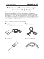
Parts or subassemblies beyond the main machine itself and external
box are all consumptive accessories and therefore are not in the
warranty scope. It is necessary for a customer to check whether there
is any defect of parts and subassemblies within 30 days dating from
the purchase date and, if any abnormality, to deliver the product to an
agent designated for marketing with the part or subassembly attached
so as to replace it with a new one.
List of Consumptive Parts or Subassemblies
●
8CH Data Pod
(Including rainbow strand group)
●
8CH Lead Set
●
Test Probe
●
USB A to B Cable
LA-100P User’s Manul
Chapter One: Product Instructions
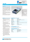
1-1 Product Overview
Since its establishment in 1980, Leaptronix has been devoting itself
to the record and measurement of IC, with the goal to provide
manufactures with a perfect R & D environment and superior
measuring instruments. Considering the measuring need of various
products in digital era, our company has intensified the combination
with various industries and established a measuring instrument
business group (Leaptronix), providing digital system with the most
important and basic instruments, i.e. the series products of logic
analyzer. The LA-100P is one of the representative of products of
the Test & Measurement.
The LA-100P is 32 channels, 250MHz timing, 100 state Logic
Analyzer. It help minimize the risk by providing the most reliable,
accurtate data captre and the most complete view of system
behavior, These products are ideally suited for you on hardwae &
software debug, parametric and mixed signal testing and complex
debugging. Moreover, their compact size and ability to connect to a
PC make it an ideal solution for use at remote sites.
-1-
LA-100P User’s Manul
Chapter One: Product Instructions
1-2 Safety and Precautions
All operations, maintenance and repair services should be subject to
following safety precautions; our company shall bear no
responsibility to any unpredictable phenomenon resulting from an
improper use of this instrument while failing to follow the
precautions presented in this manual.
1. Please confirm advance to the use of power supply that a correct
input AC voltage has been adopted and that a correct fuse has
been installed. Specific standards and specifications are shown in
the instructions of the product.
2. Before turning on the instrument, you must connect the
protective earth terminal of the instrument to the protective
conductor of the mains power cord. You must not negate to
protective action by using an extension card (power cable)
without a protective conductor (grounding). Grounding one
conductor of a two-conductor outlet is not suffieient protection.
3. Only fuses with the required rated current, voltage, and specified
type should be used.
4. Do not operate or use this product beside any flammable gas or
fumes.
5. It is prohibited to use this product with its shell dismantled, or to
adjust or replace internal parts so as to avoid improper motions
of instrument and unnecessary dangers.
WARNING!
This sign means that attention should be paid to
dangers may happen and that personal injuries will
possibly happen in case that the operator fails to operate correctly
or to follow the procedure. Under his circumstance, the operator
should not continue with the operation with a exception that he or
she indeed knows the operation procedure.
CAUTION!
The Caution sign demotes a hazard. It calls attention
to an operating procedure, practice, or the like, which,
if not corretly performed or adhered to, could result in damage to or
destruction of part of the product. Do not proceed beyond a
Caution symbol until the indicated conditions are fully understood
or met.
-2-
LA-100P User’s Manul
Chapter One: Product Instructions
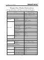
1-3 Specifications and Characteristics of Product
Items
Specifications
Time sequence analysis (frequency capture) 250MHz~25Hz(4ns~40ms)
State analysis (external clock)
100MHz~1Hz(10ns~1sec)
Bandwidth
100MHz
Channel
MEMORY
TRIGGER
Threshold Range
8CH x 4(0~31)
2M Bytes
RAM Size
Storage Depth per Channel 512kbits x 32CH
Trigger Counter
1~255
Condition
Pattern / Edge / AND / OR
Channels
32CH
Pre/Post Trigger
YES
Trigger Levels
3 (Edge or Pattern)
Continue Trigger
YES
Trigger out
YES(TTL Level)
Pulse Width Trigger
YES
Bus Analysis
YES
Glitch Capture
YES
Range
-4V~+4V
Acuracy
±50mV
Maximum Input Voltage
±30V
Impedance
100KΩshunted by 10pF
Temperature
Operating
0℃~45℃(32℉~113℉)
Storage
-40℃~75℃(-56℉~167℉)
Data Skew(Channel to Channel)
2ns typical, ±4ns MAX
Interface
USB 2.0
Power
Power Dissipation
Dimension
Power Source
AC:90~240V,50~60Hz
Fuse
AC 250V/2.0A
Normal consumed power 18.0W
Max Power Dissipation 20.0W
(Length x Width x Height) 31cm x 9cm x 15cm
3.8kg
Weight
-3-
LA-100P User’s Manul
Chapter One: Product Instructions
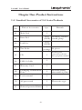
1-4 Standard Accessories of LA Series Products
NO
Title of Accessories
Qty
Remark
1
01
Main Unit
02
Data Pod
4sets Including rainbow
(32CH) strand group
03
Lead Set
4sets
(32CH)
04
Test Probe
05
CD
1
06
USB 2.0 Cable
1
07
Warranty Card
1
08
Packaging Confirmation
Form
1
09
User's manual
1
10
AC power cord
1
11
Chinese Operation Edition
1
1
package 36 pieces
-4-
Including,line,
connecting software,
drive program, manual
List out the packing
subassemblies of product
Three-wire type
LA-100P User’s Manul
Chapter One: Product Instructions
1-5 Selection of Accessories
●
8CH Data Pod
(Including rainbow strand group)
●
8CH Lead Set
●
Test Probe
●
USB A to B Cable
-5-
LA-100P User’s Manul
Chapter Two: Installation of Instrument
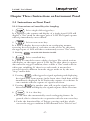
2-1 Inspection Advance to Installation
1. Although the instruments has undergone a precise test and
inspection ahead of the delivery, customers are also expected,
after unfolding the box, to confirm whether there is any
abnormality advance to use so as to confirm whether there is any
damage occurring during the delivery. After that, the product can
be used if no problem found.
2. Customers should, based on the accessory tables of various
machine types, check whether the items and quantity of
accessories in the package are correct and complete and, if not,
present the problem to our company or our local distributor
immediately for a disposal.
2-2 Places for Placement and Use
1. This instrument is formed a circulatory heat elimination system
through the fans and air holes on shell. Therefore, it should be
placed at a ventilated place. In addition, it is prohibited to block
the circulatory heat elimination holes.
2. Environmental temperature for operations and use: 0℃~45℃
3. During the operations of this product, there may be an
electromagnetic field occurring and instruments placed near it
will possibly affect one another during operations. In case of the
latter phenomenon, please keep a distance between this
instrument and any other instrument larger than 10cm. It is also
required to use it at a place far away from any high magnetic
field or interference.
2-3 Specifications of Input Power Supply
1. Advance to connecting AC power supply, please confirm the
adopted AC power supply meets the specifications of the input
voltage accepted by this instrument. The input voltage of
instrument is shown in the literal instructions on the backboard.
2. Specifications of the input voltage can be used by this instrument
are AC 90~240V, 50/60Hz.
Caution: Please confirm whether the input voltage adopted by this
instrument is in line with its specifications of voltage first.
-6-
LA-100P User’s Manul
Chapter Two: Installation of Instrument
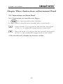
2-4 Use of Standby Fuse
In case of a need of the standby fuse, please confirm the
specifications of fuse first:
• Specifications of the adopted fuse should be 220V/2Amp.
• The product has already been enclosed with a standard fuse in the
fuse base.
Caution: Buying a new fuse to replace the original one should follow
the standard specifications, or it may lead to the damage of
instrument.
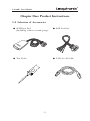
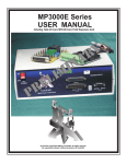
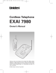
2-5 Connection of LA System
2-5-1 Connecting Sequence of LA System
(1)LA main unit →(2)Data Pod(Including rainbow strand group)
→(3)Lead Set →(4)Test Probe
Connecting Relation of system is as bellow:
(1)
(3)
(2)
(4)
※Caution: Please do not place the Lead Set on the port the LA main
unit directly to avoid the damage of the LA.
※In event of any fracture or damage, it is necessary to send the
product to the manufacturer for a repair or replacement.
-7-
LA-100P User’s Manul
Chapter Two: Installation of Instrument
2-5 Connection of LA System
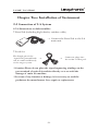
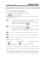
2-5-2 Instructions on Subassemblies
• Data Pod (including high-density rainbow cable)
→ Connect the Data Pod to the LA
main unit.
• Lead Set
The Single-pin of the
signal and graound leads
can be connected directly
to the target system.
→
→
Connector plugs into
the socket of data pod.
※Caution: Please do not place the signal captureing windings on the
port terminal of main LA machine directly so as to avoid the
damage of main LA machine.
※In event of any fracture or damage, it is necessary to send the
product to the manufacturer for a repair or replacement.
-8-
LA-100P User’s Manul
Chapter Two: Installation of Instrument
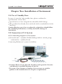
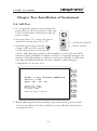
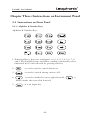
2-6 Self-Test
1. It is required to insert one terminal of
power line on AC-in position at left side
of LA and another terminal on the AC
power socket.
2. Pressing down "1" on the AC power
switch to switch from "0" to "1".
← AC Power Switch
3. And then pressing down the
← Power Socket
orange-yellow power switch
on the upper part of front panel
of LA, and then the product will be under on state; the red LED
indicator light will lighten; buzzer will give a sound lasting for one
minute; LA will undergo a self-test of system. Finally, it will enter
into the initialization frame shown as bellow, indicating the
completion of on-state test.
Moudel : Logic Analyzer 100MHz/4ns
Version : 1.01
Date : 06 / 12 / 01
System Test...PASS
Memorys Test...PASS
Load Boot...PASS
Press any key to contiune
4. While shutting down the machine, press down the power switch
for 2-3s and then loosen it, and the system will shut down after
storing the data.
-9-
LA-100P User’s Manul
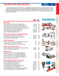
Chapter Three: Instructions on Instrument Panel
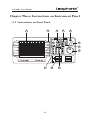
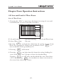
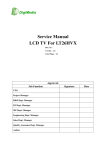
3-1 Instructions on Front Panel
3
2
1
4
5
6
7
8
Trigger Out
5V
0
LA-100P
11
-10-
10
9
LA-100P User’s Manul
Chapter Three: Instructions on Instrument Panel
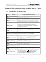
3-1 Instructions on Front Panel
NO.
Item
Function Description
1
It is a system display zone, displaying wave form,
Display Function
information and functions.
2
They are detailed hot keys of system and their
Hot keys F1~F6 adjustment should be made through the connection
with primary function-control keys on the panel.
3
Menus
Such keys include Channel, Change Page,
Auto-Scale, Cursors, File, Utility, Main delays,
Grid and Logic levels.
4
Capture
Such keys include three capture manner hot keys
(Single, Auto-store and Run/Stop) and wave form
erase hot key.
5
Power-control key It is the key acting as a power switch.
6
Direction key
It is used to control the wave form through
left-right move, zooming up & down, and to
set Sample Rate.
7
Trigger key
It is used to choose between Int/Ext Clock
and setup of Triggering state.
8
Rotary Encoder
It can be used to make left-right and bottom-top
motions of various items.
9
Character key
It is used to realize figure input and literal
editing functions.
10
Signal input port It can provide 4 sets of signal input ports.
11
Trigger Out
It can send out a " (rising) signal" to
provide to another set machine. It can be
adopted during a synchronous action.
-11-
LA-100P User’s Manul
Chapter Three: Instructions on Instrument Panel
3-1 Instructions on Front Panel
3-1-1 Instructions on Menus (Project) Control Key
1.
Channel setup key: in event of a need to set a channel,
pressing down the channel key. There are 6 functional
boxes at right side of LCD which can be used in correspondence
with hot keys F1~F6. Functions of these hot keys are as follows:
CK:4ns
S0 Delay : 0ps
100ns
Channel
On/Off
Bus
Disp Value
On/Off
Reorder
0<一 一>31
Name
On/Off
Name : GRAYWANG
Exit
-Channel on/off: to set the on or off state of various channels.
-Bus: to set bus.
-Display of numerical value: to display numerical values on
wave forms. Such item can be set as on or off state.
-In order of precedence 0~31: to conduct the order and display
various channels and their names (CH0~CH31)
-Name on/off: to switch between the display state and
non-display state of channel names. When it is on, such names
will be displayed completely; when it is off, no even one such
name can be displayed. As shown in above diagram, motion
state is on and "On" is in red.
-Exit: to set functions for the exit channel.
-12-
LA-100P User’s Manul
Chapter Three: Instructions on Instrument Panel
3-1 Instructions on Front Panel
3-1-1 Instructions on Menus (Project) Control Key
2.
It is a key to switch page.
a. In case that the quantity of channels or bus displayed on the
screen is bigger than 16, pressing down this key will switch to
the second page, that is, to display signals beyond these 16
channels; if pressing down again, will switch back to the
original.
b. If use together with the "Utility", can also realize the switch of
functional frame.
c. If use together with "Trigger", can also realize the switch of
functional frame.
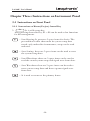
3.
Automatic adjustment key: it is for automatic search
function, search for the capture signal wave forms under existing
state and, after the search, give out a "bi" sound and automatically
display on LCD. This needs 3-5 second to show the results.
4.
It is a key to realize setup of cursor. Pressing this key
can display cursor T (there are 7 vertical cursors, i.e. A-F) and
display the time interval among various groups, i.e A~B,A~T,
B~T C~D,C~T,D~T,E~F,E~T,F~T, shown with a unit of
ns/us/ms.
※Press key "A←→B" in cooperation, and it will display that B is a
full line, which indicates that B is under the enable state; "←" and
"→"can move cursor B and change the time interval between
B~A and B~T; pressing it for another time, and it will display
cursor C and C is under a intelligent state; "←" and "→" can move
cursor C and change the time interval between C~D and C~T.
※Press key "<" to make cursor T to be enable the axis and the
fame to face left; while press ">" ,and the frame will go to right;
pressing "Λ" and "Ⅴ" will make the frame wave form switch to a
zooming-in and zooming-out state respectively.
※Pressing the cursor-setup key can return to T cursor frame. At
this time, it can be used together with the our direction keys to
make the switch among left, right, zooming-in and zooming-out.
-13-
LA-100P User’s Manul
Chapter Three: Instructions on Instrument Panel
3-1 Instructions on Front Panel
3-1-1 Instructions on Menus (Project) Control Key
5.
File
It is a file-setup key.
After pressing down this key, F1~F4 can be used as hot functions
for file management.
- Load Setting: It possesses 5 space items for choice. The
precondition is that there must be system setup data
stored, only under this circumstance, setup can be read
and used.
- Save Setting: there are 5 space items can be used to store
the system setup data.
- Load Waveform: there are 5 space items can be used to
read the stored system setup and signal wave form data.
- Save Waveform: there are 5 space items can be used to
store system setup data and those capture signal wave
form data.
- It is used to return to the primary frame.
-14-
LA-100P User’s Manul
Chapter Three: Instructions on Instrument Panel
3-1 Instructions on Front Panel
3-1-1 Instructions on Menus (Project) Control Key
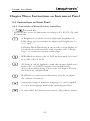
6.
General Key:
Press this key to use its functions according to F1, F2, F3, F4, and
F5 functions.
- a. Brightness: it can be used to adjust the brightness of
LCD; there are two manners to adjust such brightness, i.e.
"++" and "- -".
b.Display Mode Waveform: it can set the screen display in
a wave form or in literal. (If used together with "Change
Page", it can also be used to switch page.
- B/W (black or white color of LCD background): it is used
to set the color of LCD.
- PC-Link: it can be applied to send the capture signal wave
form to PC via USB2.0 interface for magnification,
observation and printing. Please refer to Chapter Five for
the details of computer link.
- RAM Size: it can be used with rotary encodor to adjust
the volume of memory.
- Language (setup of interface language): it can be applied
to select the language used in the operating interface.
- It can realize the function to return to the primary frame.
-15-
LA-100P User’s Manul
Chapter Three: Instructions on Instrument Panel
3-1 Instructions on Front Panel
3-1-1 Instructions on Menus (Project) Control Key
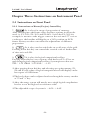
7.
It is a key for setup of proportion of memory.
After entering into the frame, there are three options in all can be
used, i.e. F1: 10%, F2: 50% and F3:90%. Let's take F2: 50% for
example, it means to take trigger center as the axis and “T” axis as
a reference, the baseline will display at a 50% position on LCD
frame. Rotary encoder can realize the adjustment of different
proportions.
8.
It is a key used to switch the on or off state of the grid .
Pressing down this key can control the vertical scale of broken line
of time axis on LCD.
9.
It is a key for logical comparison level key.
Pressing down this key can cooperate with hot keys F1~F3 to set
and change logical comparison level key. System preset value are:
TTL:1.5V CMOS:2.5V ECL:-1.3V
※After pressing down this key and selecting one option among F1,
F2 and F3, the value of logical comparison level will display on the
lower part of LCD frame.
※The level values can be adjusted and set through the rotary encoder
or"V"and"Λ"key.
※After the setup, system will merely use a single logical compilations
level to act as the high or low reference value.
※The adjustable scope of system is -4.0V~+4.0V.
-16-
LA-100P User’s Manul
Chapter Three: Instructions on Instrument Panel
3-1 Instructions on Front Panel
3-1-2 Instructions on Control Keys for Sampling:
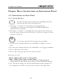
1.
It is a single-click trigger key:
It is applied to the capture and display of a single signal. LCD will
display a "Pat" mark on the upper part of LCD. The signal capture
will stop immediately once realized.
2.
It is an auto-store key:
It is used to display the test results in an overlapping manner,
reserving the test results of each time on the screen. At this time,
the upper part of LCD will show continuously reverse "Pat" mark.
※ Pressing
3.
can make this function invalid.
It is a start/halt key.
It is used to control the start or halt of trigger. The switch actions
will display on the upper part of LCD. In case that there is capture
data meet the trigger condition, there will be a "Pat" mark with its
white part twinkling. If there is no such mark, it means that
external signal is different from the trigger mode set by the user.
"Stop" means halt.
※ Pressing
will trigger the signal, updating and displaying
the signal wave form capture in the latest time. Such data will be
immediately displayed on LCD after the capture of each time. It
can continue with the capture of signal wave form.
※ Pressing
for another time will stop the signal capture.
After that, LCD will display the signals capture in the last time.
4.
It is a clear key.
a. It can clear the automatically saved overlapping frames. In
general, this is a function in cooperation with the auto-store key.
b. Under the functional list of Trigger, pressing such key which
can set the trigger condition for all channels to be "Don't Care".
-17-
LA-100P User’s Manul
Chapter Three: Instructions on Instrument Panel
3-1 Instructions on Front Panel
3-1-3 Instructions on Control Keys for Trigger
1.
It is an internal/external clock key.
It can be used to switch between internal and external modes.
- Internal mode: it is triggered by the internal clock signal
of LA, i.e. asynchronous trigger mode or time mode.
- External mode: it is triggered by the external clock signal
of LA, i.e. the synchronous trigger mode or state mode.
※The selected mode will make the characters in blue.
-18-
LA-100P User’s Manul
Chapter Three: Instructions on Instrument Panel
3-1 Instructions on Front Panel
3-1-3 Instructions on Control Keys for Trigger
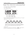
2.
It is the trigger key.
After pressing down this key, F1~F5 stand for the trigger manners
which can be selected.
- a. Continuous on/off: it is used to set the multi-level trigger
condition to be continuous or non-continuous.
b. Trigger times: it is used to set which times of the trigger.
(Can be switchable by using
).
- a.Pat 1: it means to select the single-level trigger condition
(Can be switchable by using
).
b. Pulse wave width: it is used to set the trigger condition
of pulse wave width by making use of ">", "=" and "<".
- Pat 2: it means to select the two-level trigger condition.
- Pat 3: it means to select the three-level trigger condition.
- OR Pat: it means to execute the trigger condition of "OR".
※Setting for trigger condition:
F1: L (Low)
F4:
F2: H (High)
F3: X (Don't Care)
F5:
F6:Back
(Active High rising) (Active Low falling)
※Use the rotary encoder to move the red cursor to the various channels.
※Then, pressing keys F1~F5 for seting the trigger state of this channel.
※Each channel can be displayed on screen for setup or amendment.
Those channels beyond consideration can be set as "Don't Care" or
to not display on the LCD screen. To quit this setup, just press F6.
-19-
LA-100P User’s Manul
Chapter Three: Instructions on Instrument Panel
3-1 Instructions on Front Panel
3-1-4 Alphabet & Number Keys
Alphabet & Number Keys
.﹝﹞
1. Numerical keys: there are ten figures, i.e. 0, 1, 2, 3, 4, 5, 6, 7, 8
and 9. The English letters and other symbols contained by these
numerical keys can be showed by pressing this key.
2.
: it can be used to cancel characters.
3.
: it used to switch among cursors A-F.
4.
5.
is used to make the cursor right forward,
used to make the cursor left forward.
: it is an input key.
-20-
is
LA-100P User’s Manul
Chapter Three: Instructions on Instrument Panel
3-1 Instructions on Front Panel
3-1-5 Special Hot Keys:
Is a key for selection of directions including upward,
downward, leftward and rightward.
1. Pressing "Λ" and "Ⅴ" can realize the magnification,
zooming-down, logical level, trigger level and Sample Rate
selection of wave form.
2. Pressing "<" and ">" can make the wave form to be observed
from forward and backward directions. Under the trigger, the key
can move the level.
Is a rotary encoder. It has functions as bellow:
1. To select the channel which you would like to display or to set
title.
2. To select the channel which you would like to set trigger condition.
3. To set the logic level value.
4. To set the storage proportion of memory data.
Hot keys: F1~F6
1. They are used to relate to F1~F6 functions during setup of
Channel/File/Utility/Main delays/Logic levels/INT/EXT/Trigger.
2. F1~F6 can be subject to the functional instructions display on
the right side of LCD screen by the system at the right time.
-21-
LA-100P User’s Manul
Chapter Three: Instructions on Instrument Panel
3-1 Instructions on Front Panel
3-1-6 Trigger Out Port:
1. Port1~4: there are 4 sets of
Trigger Out
5V
0
Port 1 stands for CH0~CH7.
Port 2 stands for CH8~CH15.
Port 3 stands for CH16~CH23.
Port 4 stands for CH24~CH31.
Each port will use one set of data pod and one Lead set of 10-signal
capture lead (including GNDx2).
2. Base square-wave Clock:
LA-100P provides one set of 5v square-wave Clock for the
calibration and self-measurement of each channel. During the
operation, the base square-wave of a channel can be displayed
on the screen via contacting the Probe Lead or hook.
3. Trigger Out:
When the LA is triggered, it will send out a "
" (rising) signal to
provide to another instrument for synchronous motions.
-22-
LA-100P User’s Manul
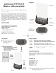
Chapter Three: Instructions on Instrument Panel
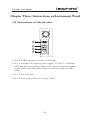
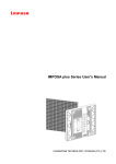
3-2 Instructions on Side Interface
1
2
3
4
1. It is a USB2.0 interface for use of PC-Link.
2. It is a switch for AC input power supply ("0" and "1" stands for
OFF and ON respectively). The power switch on the front panel
can be valid only when this AC power switch is under an ON
state.
3. It is an AC fuse base.
4. It is a three-plug socket for AC power line.
-23-
LA-100P User’s Manul
Chapter Three: Instructions on Instrument Panel
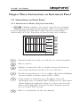
3-3 Instructions on Rear Panel
Diagram for Rear Panel:
1. Instructions on cautions
2. Instructions on Product Title and S/N
3. Safety regulations
-24-
LA-100P User’s Manul
Chapter Four: Operation Instructions
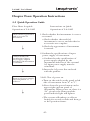
4-1 Quick Operation Guide
Instructions on Quick
Operations of LA-100P
Flow Chart for quick
Operations of LA-100P
check model, appearance
and accessories of
instrument
↓
confirm whether the
specification of input
power supply adopted
and that of the instrument
is coincident.
↓
Turn-on of power supply
and completion of
self-test
↓
1.Check whether the instrument is correct
or normal.
a.Check whether the model of
instrument is correct and whether its
accessories are complete.
b.Check the appearance of instrument
is normal.
2.Confirm the specifications of input
power supply of instrument.
a.Confirm that the specifications of
power supply adopted by the
instrument and that of the external
AC input power supply must be
coincident.
b.Insert the AC power line enclosed
with the product.
3.Self -Test of power on
a.Turn on the switch on the panel at left
side of instrument from "0" to "1”.
b.Press down the power button on the
upper right on front panel of
instrument. When power on, there is a
“bi” given by the buzzer and the
power indictor light will lighten.
c.The system will undergo a self-test
lasting for several seconds and then go
to the operation frame.
-25-
LA-100P User’s Manul
Chapter Four: Operation Instructions
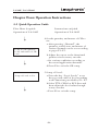
4-1 Quick Operation Guide
Flow Chart for quick
Operations of LA-100P
↓
(0~32) Set the quantity
(0~32) and names of CH
to use
↓
Instructions on Quick
Operations of LA-100P
4.Set the quantity and names of CH to
use
a.After pressing “Channel”, the
quantity, on/off state and names of
various channels can be set according
to pages F1~F5.
b.Adjust the cursor to the functional
position via the rotary encoder.
c.Set various conditions according to
the actual application demands.
d.Press F6 to exit the CH setup.
5.Setup of Level:
Setup of Level to Use
↓
a.Press the key “Logic Levels” to set
the type and value of level according
to the functions provided by F1~F3.
b.Select TTL, CMOS or ECL first and
then adjust the level value through
rotary encoder.
c.Press F6 to exit the setup.
-26-
LA-100P User’s Manul
Chapter Four: Operation Instructions
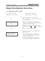
4-1 Quick Operation Guide
Flow Chart for quick
Operations of LA-100P
↓
Set the trigger state of
each CH (Trigger State)
↓
Execute the trigger and
complete the signal
contraction. OK
Instructions on Quick
Operations of LA-100P
6.Set the trigger state of each CH
a.Press “Trigger” to enter into the setup
of trigger state.
b.Move to various channel through
rotary encoder. The red position is the
place for channel setup.
c.And then select one among the Low,
High, X and〝 〞〝 〞according
d.Press F6 to exit the setup.
7.Execute the trigger and complete the
signal capture.
a.Power on the DUT and then press
down "RUN/Stop" to capture the
trigger signal in need.
b.Or to press "Single" to capture the
single trigger signal and then stop.
-27-
LA-100P User’s Manul
Chapter Four: Operation Instructions
4-2 Turn on the System Power Supply
1. Confirm that the specification of AC power supply adopted is
coincident with that specification concerning input of the
instrument.
2. Pull the AC power switch
on left side of LA from "0" to "1"
so as to start up the AC power supply.
3. After pressing down the power switch on the upper right of front
panel of LA, the red LED light will lighten, buzzer will give a
sound sounding like "bi" and LCD screen will display characters
such as self-test.
4.After the completion of self-test of system, LCD will, at its lower
part, display information of "
Press any key to continue . . . ".
Then, enter into the operator interface by pressing any key (except
for the power switch), or enter into the interface automatically after
8 seconds.
-28-
LA-100P User’s Manul
Chapter Four: Operation Instructions
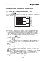
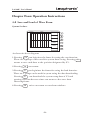
4-3 Setup the Channel Quantity and Titles
1.Pressing
can login into the channel-setting page as bellow:
To select the channel which you would like to amended by using the
rotary encoder first.
CK:4ns
S0 Delay : 0ps
100ns
Channel
On/Off
Bus
Disp Value
On/Off
Reorder
0<一 一>31
NameOn/Off
Name : BUS00
Exit
↑
It is used to set or change the channel names. At the LCD lower left
side shown:
Name : BUS00
↑
Instruction: 1. BUS00 under "Name" refers to the name of CHO.
2."↑" is the place where the channel name should be input. After
changing it, the surplus characters can be deleted by pressing
"DEL" directly. The channel name can include 8 letters at most
and can be a combination of English letters and figures.
3. After pressing
, CHO can change the name and switch the
channel via rotary encoder.
4. Pressing
can quit out this setup.
F1 :It is used to display or not display this channel. Rotate the
rotary encoder to set the selected channel and then press
down F1.
F2 :It can provide 16 sets of bus display. Each set of bus can
bear 2-16 channels.
F3 :It is used to set the numerical values, ON means to display
and OFF means not to display.
F4 :It is used to display channels on the screen in a CH0~CH31
sequence.
F5 :It is used to select the display or non-display state of switch
key of this channel. When “On” is in red, it means to
dispaly names of various channels; when OFF is in red, it
means not to display such names.
F6 :Pressing it can quit out this page.
-29-
LA-100P User’s Manul
Chapter Four: Operation Instructions
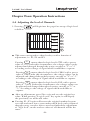
4-4 Adjusting the level of Channels
1. Pressing
as bellow:
will login into the page fore setup of logic level
2
TTL
16 C E
17 O E
18 W E
19
20
21
22
23
CMOS
ECL
24
25
26
27
28
29
30
31
Tr i gge r Vo l t age
1.3V
●
This state corresponds to three hot keys with a function of
adjustment, i.e. F1, F2 and F3.
Pressing F1 means that the logic level is TTL with a preset
value of 1.5v. Under this circumstance, the voltage values can be
adjusted and changed through the rotary encoder or "V" or "Λ"
according to the voltage of signal which would like to capture.
Pressing F2 means that the logic level is CMOS with a preset
value of 2.5v. Under this circumstance, the voltage values can be
adjusted and changed through the rotary encoder or "V" or "Λ"
according to the voltage of signal which would like to capture.
Pressing F3 means that the logic level is ECL with a preset
value of -1.3V. Under this circumstance, the voltage values can
be adjusted and changed throught eh rotary encoder or "V" or
"Λ" according to the voltage of signal which would like to
capture.
●
After an adjustment, press F6 to exit and save the original set
value. When pressing “Logic Levels” key again, it will dispaly
the previously set mode and value.
●
Pressing F1~F3 again will restore the original standard system
set value and enter into a state under which level can be adjusted
through rotary encoder. After a user has finished the adjustment
of "logic level", modes and set values of all channels will be the
same.
-30-
LA-100P User’s Manul
Chapter Four: Operation Instructions
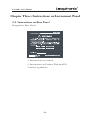
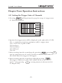
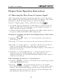
4-5 Setting the Trigger State of Channels
1.Pressing
will login into the page for setup of trigger state
of channels as bellow:
CK:4ns
Delay : 0ps
100ns
Coutinuous
On/Off
Part 1
Part 2
Part 3
OR Pat
Exit
2.Options for trigger states will be displayed at the right side of LCD.
F1: a. continuous (on)/non-continuous (off) b. trigger times
F2: a. level one, b. pulse width
F3: level two
F4: level three
F5: OR level
F6: exit
3.After entering into the second page by pressing
, pressing F1
can, in cooperative use of rotary encoder or numeric keyboard, set
the which times the trigger to be happen.
4.After entering into the second page through pressing
,
the trigger condition of pulse wave width can be set by ">", "="
and "<" after pressing
(setting manner is shown in 6-2-b
F2
of Chapter Six).
-31-
LA-100P User’s Manul
Chapter Four: Operation Instructions
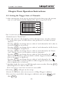
4-5 Setting the Trigger State of Channels
5.After entering into level one by pressing F2 on the first page, the present
state of each channel will be displayed at the lower part of LCD.
CK:4ns
S0 Delay : 0ps
100ns
LowL
L
HighH
H
Don't Care
X
Active High
Active Low
Part 1 xxxxxxxx xxxxxxxx xxxxxxxx xxxxxxxx
Back
Pat 1 xxxxxxxx xxxxxxxx xxxxxxxx xxxxxxxx
※Initial state is "Don't Care".
6.Move the cursor to the channel position through rotary encoder, and the
"x" at the lower part of LCD refers to the position of set value for such
channel.
Pressing F1 can change the set value of such channel to be L, that is,
to set the trigger at a low level.
Pressing F2 can change the set value of such channel to be H, that is,
to set the trigger at a high level.
Pressing F3 can change the set value of such channel to be "Don't
care", that is, to set it to be under a state of ignorance.
Pressing F4 can change the set value of such channel to be "
",
that is, to set it under a state in which it will be triggered when switching
from a low level to a high level.
Pressing F5 can change the set value of such channel to be "
",
that is, set it under a state in which it will be triggered when switching
from a high level to a low level.
7.And then make the cursor to CH1 through rotary encoder. Pressing F2
will change the set value of CH1 to H.
Pat 1 xxxxxxxx xxxxxxxx xxxxxxxx xxxxxxHL
8.Pressing F6 will quit out the setup.
※In the 32 channels, only can set one set of Edge Trigger condition.
※In a need to cancel all of the trigger conditions, just press
then Erase
-32-
and
LA-100P User’s Manul
Chapter Four: Operation Instructions
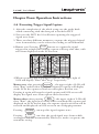
4-6 Executing Trigger Signal Capture
1. After the completion of the whole setup, use the probe hook
which connecting with the data pod to hook the DUT.
2. Power on the DUT, the LA will start capturing the triggered
signal wave form.
3. There are three different manners to capture the triggered signal
wave form and they can be selected according to actual demand.
4.Manner one: Pressing Single means to capture the signal
triggered in a single time and the capture will stop after that, with
wave form displayed on the LCD screen.
※When executing and stopping the capture, the upper right of
LCD will display "Run" and "Stop" respectively.
Manner two: after pressing Run/Stop , the upper right of LCD will
show "Run" and the first signal wave form the capture will display
on the LCD; the capture second one will replace the first one.
Pressing it again will stop the signal capture and LCD screen will
display the signal wave form capture in the last time.
Auto-
Manner three: after pressing
, the upper right of LCD will
Store
show "Run"; the signal wave form will be automatically capture and
displayed on LCD. At this time, the capture signal wave form will be
reserved and displayed on LCD screen in an overlapping manner.
Pressing
Run/Stop
can stop this signal capture state.
Erase
Pressing
can clear the saved signal wave forms which
overlapped on LCD automatically. This key is used to cooperate the
automatic saving.
-33-
LA-100P User’s Manul
Chapter Four: Operation Instructions
4-7 Observing the Wave Form of Capture Signal
After captureing the trigger signals through any one of the above
three manners, the observation can be done according to the actual
demands to check the signal forms of various channels.
Switch of display pages can be realized by pressing
1. LA-100P can use and display 32 CH; while one LCD screen can
display 16 CH. The observed page can be changed to Page1 or
Page2 though the page-switch key.
2. Contents displayed on Page1 and Page2 are CH0~CH15 which is
the preset value and CH16~CH31 respectively.
Zooming-in, zooming-out and T Cursor Replacement of Wave Form:
1. Pressing
LCD screen
above "Λ"can zoom in the wave form on
2.Pressing "Ⅴ" below can zoom out the wave form on LCD screen.
3.Pressing "< "at left side of < can move the T cursor to left; in
event of a fixed sampling rate, then the recruitment of
replacement a delay of each time should be subject to the times of
zoom-in or zoom-out.
4. Pressing ">" at the right side of > can move the T cursor to
right; in event of a fixed sampling rate, then the data of
replacement delay of each time should be subject to the times of
zoom-in or zoom-out.
Time Calculation of Cursors A~F and T Cursor:
1. Pressing Cursors , cursors A~F and T Cursor will emerge on the
LCD page at the same time.
2.Pressing
can switch among cursors A~F and the
selected one will be a solid line. "→" and "←" can be used to move
cursor to the initial and ending position of the wave form to be
calculated, and the lower part of the wave form will display the
time difference between the two cursors.
-34-
LA-100P User’s Manul
Chapter Four: Operation Instructions
4-8 Save and Load of Wave Form
Save of Wave Form
1. Pressing the “File” to enter into the frame for setup of save and
load functions of wave form data as bellow:
CK:4ns
Delay : 0ps
100ns
Load Setting
Save Setting
Load Waveform
Save Waveform
Exit
F1: Load Setting
F4: Save Wave form
F2: Save Setting
F6: exit
F3: Load Wave form
F4
2.Pressing
can login into the frame for saving of wave form.
F1
There are 5 groups for saving wave form data. Press
to
save such data on the position by F1.
3. Pressing
F6
will return.
F3
4. Pressing
can login into the frame for seting loading the
wave form. There are 5 groups of data for downloading.
F1
Pressing
at this time can download the wave form data
F6
of F1 and pressing
for another two times can return to
the wave form observing frame.
-35-
LA-100P User’s Manul
Chapter Four: Operation Instructions
4-8 Save and Load of Wave Form
System Set Save
CK:4ns
Delay : 0ps
100ns
User 1
User 2
User 3
User 4
User 5
Back
As shown in above diagram:
1.Pressing F2 can login into the frame for seting the save function.
There are 5 groups can be used for system data saving. Pressing F1
means to save such data to the position designated by F1.
2.Pressing
F6
can return.
3.Pressing F1 can login into the frame for seting the load function.
There are 5 groups can be used for sytem seting the data downloading.
Pressing F1 can download the system setup data of F1 and
pressing it for another two times can return to the wave form
observing frame.
4.Pressing
F6
twice can return to wavefrom windows.
-36-
LA-100P User’s Manul
Chapter Four: Operation Instructions
4-9 Power off LA System
1.Under the power on state, in order to shut down LA, just press
down
2.Will emerge at the lower part of LCD screen after that.
Save Boot Wait . . . .
The LA will be shot down after 3-4s after the system save the data.
3.Shut down AC power supply or pull put AC power line.
In case that the instrument will not be used for a long term, it is
necessary to close the AC Power switch at left side of LA by
switching from "1" to "0".
-37-
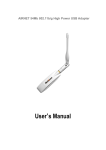
LA-100P User’s Manul
Chapter Five: Use of PC-LINK
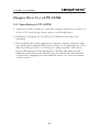
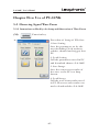
5-1 Installation of PC-LINK
1. Adoption of PC- Link is to send the capture signal wave forms on
LA to a PC for saveing, observation, search and print.
2. USB 2.0 is adopted by LA. The LA USB driver needs to be
installed.
3. To install the PC-Link application software which enclosed with
LA-100P (or downloaded from the website of Leaptronix) to a PC.
The first thing to do is to decompress the program. After that,
there will emerge the install button. Clicking this button and
following what shown on the PC page can finish the installation.
4. After the completion of installation, there is a LA icon shown
on the screen.
-38-
LA-100P User’s Manul
Chapter Five: Use of PC-LINK
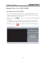
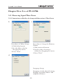
5-2 Operations of PC-LINK
1.In case that the LA-100P has capture the triggered signal wave
forms, such signal wave forms can be uploaded to PC through a
USB 2.0 interface for observation.
2.After pressing
on the LA main unit, LCD will display
F1~F5.
Selecting F3, the PC Link function and pressing it down. The
LA-100P has prepared for the transmission of wave form data.
3.Clicking icon of
on the PC, get into the following page.
-39-
LA-100P User’s Manul
Chapter Five: Use of PC-LINK
5-2 Operations of PC-LINK
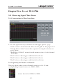
5-2-1 Uploading the Signal Data of the LA Main unit into PC
1. After logging into the operating system, click "Start/Stop".
2. After detecting the hardware of LA, PC will download the signal
wave form capture motions of LA shown the following page:
3. If the PC shows signal wave forms, it means the uploading has
been finished.
-40-
LA-100P User’s Manul
Chapter Five: Use of PC-LINK
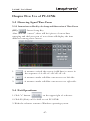
5-3 Observing Signal Wave Form
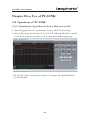
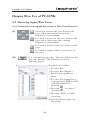
5-3-1 Instructions for Wave Form Data
1. List the signal wave by 8 channels on the upper part of page.
"Scale =2.5ms" means that the time of each grid on the page is 2.5s.
"Sample Rate=100us" means that capture the singal each time on
every 100us.
"RAM Size=512 bits" means that the memory size of each channel
is 512 bits.
"Pat1" refers to the trigger condition for level one.
"Pat2" refers to the trigger condition for level two.
"Pat3" refers to the trigger condition for level three.
5-3-2 Quantity and Names of Channels
The page shows that current channel quantity is 24 ~31 and
corresponding channel names are CH24~CH31.
means the title of CH24' is CH24.
-41-
LA-100P User’s Manul
Chapter Five: Use of PC-LINK
5-3 Observing Signal Wave Form
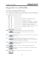
5-3-3 Instructions on Setup and Observation of Wave Form Functions
(I) :It used to zoom in the wave form on the
page and to increasing the scanning
frequency of instrument.
:It is used to zoom out the wave form on the
page and to decreasing the scanning
frequency of instrument.
:It is used to leftward the wave forms on the
page.
:It is used to rightward the wave forms on
the page.
(II) :it is a channel function key. You can click to set the
bus and channels. The functions are as the
following figure:
a.
Procedure of set Bus.
1.To select Bus.
2.To select Bus (Bus00~
Bus15) in the pulldown
menu.
3.To select the channels in a
sequence from MSB to LSB
and add channels by
pressing
4.Pressing
to remove
channels.
5.Pressing "YES" to finish
the setup.
6.Pressing Exit to quit out
the setup.
-42-
LA-100P User’s Manul
Chapter Five: Use of PC-LINK
5-3 Observing Signal Wave Form
5-3-3 Instructions on Hot Keys for Setup and Observation of Wave Forms
b.
Procedure of Channel Setup
1.To select channel.
2.Click the box ahead of channel
which you would like to display.
3.Pull-down menu is able to
display or delete all the passages.
4.Pressing "YES" to exit.
(III)
Auto-Scale: it means to search the channels
possessing signals and display them on screen
automatically.
(IV)
Auto-Store: it means to save all of the test results on
the screen.
(V)
Erase (deletion key): it means to erase the test
results on the screen. This key is to be used with the
automatic adjustment function.
(VI)
Change Page ( page switch key): it is used to switch
the display page.
(VII)
Single: it refers to single-time signal capture.
(VIII)
Run/Stop: it means to continue or stop the signal
capture.
(IX)
Print: it means to print the test results.
-43-
LA-100P User’s Manul
Chapter Five: Use of PC-LINK
5-3 Observing Signal Wave Form
5-3-3 Instructions on Hot Keys for Setup and Observation of Wave Forms
(X)
a.
Trigger Opt (trigger function key): it is used to set
trigger level and mode. Press and enter into trigger
function as the following page:
Procedure of Setup of Trigger
level:
1.Directly click to set the chosen
elements.
2.Drag the cursor to set the trigger
level.
3.Press "Yes".
4.Press "Exit".
b.
Procedure for Setup of Trigger Mode
1. To set continuous trigger on/off.
2. To select the level quantity through pulldown menu.
3. Click the frame of Pat to set the trigger mode.
4. Press "Yes" key.
5. Press "Exit" key.
-44-
LA-100P User’s Manul
Chapter Five: Use of PC-LINK
5-3 Observing Signal Wave Form
5-3-3 Instructions on Hot Keys for Setup and Observation of Wave Forms
(XI)
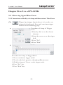
a.
Function key
Procedure of Setup of File Save
1.Save Setting
Save the parameters set by the
user (including Clock, memory
volume, channel and trigger) into
PC.
2. Load Setting
Call the parameters saved in PC
and download them to LA-100P.
3. Save Image
Save the current test results of
the wave to the PC in a bmp
format.
4. Load Image
Call the wave form results saved
in PC. However such results can
not be downloaded to LA-100P.
-45-
LA-100P User’s Manul
Chapter Five: Use of PC-LINK
5-3 Observing Signal Wave Form
5-3-3 Instructions on Hot Keys for Setup and Observation of Wave Forms
b.
c.
Procedure of Delay Setup:
1.Click delay button.
2.Set the delay value by
dragging the cursor.
3.Press "Exit"
Procedure of Setup the Memory
Volume
1.Click universal button.
2.Set the value of memory
volume by dragging the cursor.
3.Press "Exit"
d.
Language Setup
Language can be selected among
English, classified Chinese and
simplified Chinese.
-46-
LA-100P User’s Manul
Chapter Five: Use of PC-LINK
5-3 Observing Signal Wave Form
5-3-3 Instructions on Hot Keys for Setup and Observation of Wave Forms
(IIX)
Cursor Setup Key
After click the “cursor”, there will be 6 pieces of cursor lines
emerging and the lower part of wave form will display the time
difference among these cursors.
1.
: it means to switch the cursors (solid lines) to move in
the sequence of A→B→C→D→E→F→A.
2.
: it means to make solid-line cursors move to left side.
3.
: it means to make solid-line cursors move to right side.
5-4 Exit Operations:
1. Click "x" button
on the upper right of software.
2. Click F6 (Exit) on LA-100P to exit PC-LINK.
3. Make the software return to Windows operating system.
-47-
LA-100P User’s Manul
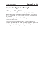
Chapter Six: Application Example
6-1 Capture of Simple Data
In case that you would like to observe the signals for DUT, but no
idea about the logic level and trigger manner. Please just connect
the LA. The signals will show on the LCD quickly. Operating steps
are as bellow:
1. Connect the probe hook with the DUT signals.
2. Press key Auto-Scale.
The LA can set the sampling frequency, logic level and trigger
condition automatically. No matter how many channels, Auto-Scale
function will automatically set each channel and display the
measuring results with an optimum display manner.
-48-
LA-100P User’s Manul
Chapter Six: Application Example
6-2 Capture of Specific Events
a.In case of a need to observe the specific events, you can use the
function of set trigger condition. For example, to capture the
continuous data 00, 01, 02 of counting register on 8 bits. The
procedure is as follows.
1. Press down the key of “Logic Levels” to set a logic level.
2. Press down the key “Trigger”.
3. Press F1 to set on.
4. Press down F4 to set three-level trigger condition.
5. Rotate the rotary encoder to set the conditions of channels on
the level one as
XXXXXXXX XXXXXXXX XXXXXXXX LLLLLLLL
orderly.
6.Press "Ⅴ" to make the red cursor downward move to the level
two.
7.Rotate the rotary encoder to set the conditions of channels on
the level two as
XXXXXXXX XXXXXXXX XXXXXXXX LLLLLLLH
orderly.
8.Press "Ⅴ" to let the red cursor downward move to the level
three.
9. Rotate the rotary encoder to set the conditions of channels on
the level three as
XXXXXXXX XXXXXXXX XXXXXXXX LLLLLLHL
orderly.
10. Press F6 to return and exit.
11. Press Run/Stop to execute the signal capture.
-49-
LA-100P User’s Manul
Chapter Six: Application Example
6-2 Capture of Specific Events
b.In case of a need to observe the specific events input with digital
signals, you can use of the function of set the trigger condition.
For example, to capture the pulse wave width smaller than 4uS on
the condition of the 8 bits counter CH0 High.
1. Press key Trigger.
2. Press Change Page to enter into the next page.
3. Press F2 to set the conditions of pulse wave width.
4. Rotate the rotary encoder to set Channel as Ch.0.
5. Press ">" to move the cursor leftward.
6. Rotate the rotary encoder to set condition H.
7. Press ">" to move the cursor rightward.
8. Rotate the rotary encoder to set the condition as "<".
9. Press ">" to move the cursor rightward.
10. Input figure "4" through the rotary encoder or the figure key.
11. Press
to rotate the rotary encoder to set the unit as uS.
12. Press F6 to exit the setup.
13. Press Run/Stop to execute the signal capture.
-50-
LA-100P User’s Manul
Chapter Six: Application Example
6-3 Details of Signal Analysis
To analyze the measured signals, you can use the following three
procedures. For example, if you would like to search information
"00". And would like to know whether the interval among such
information emerging each time is the same or not.
The procedure is as below:
a. Setup of Bus Function
1. Press "Channel".
2. Press F2 to set Bus.
3. Rotate the rotary encoder to select Bus00. Pressing "<", can
combine the selected channel in this Bus.
4. After rotating the rotary encoder and selecting channel. Press
down Enter, the selecting order should be MSB~LSB. After
completely selecting, the channel is combined, press down F6 to
return and exit.
5. Press Run/Stop to execute the signal capture.
6. Pressing Run/Stop for again to halt the signal capture.
b. Running of Search Function
1. Press down key Enter.
2. Press F2 to set the search condition.
3. Rotate the rotary encoder to select Bus00. Pressing ">" and
rotate the rotary encoder to set the condition as "00".
4. Press key Enter.
5. Press F4 to search the last data.
-51-
LA-100P User’s Manul
Chapter Six: Application Example
6-3 Details of Signal Analysis
c. Measurement by Useing Cursors
1. Press key “Cursors.”
2. Move cursor A to the initial position 00 of the wave form by
useing " → "and " ← ".
3. Press F5 to search the next data.
4. Press
to select cursor B.
5. Move cursor B to the initial position 00 of the wave form by
using" → "and " ← ".
6. Press F5 to search the next data.
7. Press
to select cursor C.
8. Move cursor C to the initial position 00 of the wave form by
using" → "and " ← ".
9. Press F5 to search the next data.
10. Press
to select cursor D.
11. Move cursor D to the initial position 00 of the wave form by
using" → "and " ← ".
12. The time difference between any two cursors will display at the
lower part of the wave form.
13. Press F6 to exit the search function.
-52-
LA-100P User’s Manul
Chapter Six: Application Example
6-4 Setup of Advance or Delay Trigger
To look up the data of the certain time point advance or behind the
trigger point, you can use the Advance/delay function. For example,
if you would like to look up the data of 1ms behind the trigger
point. The procedure is as below.
1. Set Trigger condition.
2. Press key Enter.
3. Press F1 and there will be a dialog box reading
"±000s000m000u000n000p" emerge on the screen.
4. Rotate the rotary encoder to move the cursor.
5. Press the figure key 0 and set symbol as "+", which means to
delay the trigger (press the figure key - and set symbol as "-",
which means to set the advance trigger.
6. Rotate the rotary encoder to set the time as 1ms.
7. Press key Enter.
8. Press Run/Stop to execute the signal capture.
6-5 Save of Test Results
In case of a need to keep the test results for further analysis, you
can save the wave form data by following steps:
1. Press key File.
2. Press F4 to save the wave forms.
3. Press F1 to save the wave forms to USER 1.
4. Press F6 to return and exit.
5. Press Rrn/Stop to execute the signal capture.
-53-
LA-100P User’s Manul
Chapter Six: Application Example
6-6 State Test
To conduct a state test, following steps should be done:
1. Connect the external CLK with the 32nd channel.
2. Press key Int/Ext.
3. Press F2 to set it as an external CLK. At this time, the CK
position of the upper left of screen will display Ext.
4. Press F6 to return and exit.
5. Press Rrn/Stop to execute the signal capture.
6-7 Remote Control
In case of a connection need with PC, operating steps are as bellow:
1. Connect USB Cable with the LA and PC.
2. Press key Utility.
3. Press F3 to connect with PC.
4. Run the LA software on PC.
5. When finish the Remote Control, press F6 to end the connection
with PC.
-54-
LA-100P User’s Manul
Chapter Seven: Instrument Calibration
Instruction
The instrument, after a period of use (one year in general), will be
error between the defined value and the value at input/output
because of many factors. Therefore, the LA needs to do calibration.
7-1 Calibration Manner
There are two conditions of calibration:
1. The instrument user sends the instrument back for a calibration.
Our company will present a calibration statement on ex-factory
check result. The calibration charge is needed.
2. When the goods send back for repair, we will change the spare
part and suggest the user to do the calibration if necessary. (The
calibration fee shall be extra listed in the Maintenance Fee List).
※The maintenance and calibration during the warranty period
should be subject to the provisions of Warranty.
※We currently do not provide self-calibration of users.
-55-
LA-100P User’s Manul
Chapter Eight: Repair, Maintenance and Use
Instruction
The difference between maintenance and repair of instrument is as
bellow: maintenance is implemented by users themselves. The repair
is implemented through sending the instrument to the
manufacturer. Instructions are as bellow:
8-1 Maintenance Implemented by Users
1. The users should implement maintenance under the precondition
not to dismantle the shell of machine.
2. In case that the instrument adopts a correct AC input power
supply, under this circumstance, if there is no any reaction by
power on the Power Switch on the panel at left side on "1" and
pressing the key Power on the front pannel. The problem may be
the burning of fuse. When replacing the fuse, please pull off the
AC power line first, and then open the fuse case and replace the
old fuse with a standard one.
◎Caution: The failure of adopting the standard fuse will possibly
lead to damage, burning of the instrument or a serious fire
hazard. If so, the users fail to enjoy the warranty services.
3. Do not to cover or block the air holes of instruments so as to
ensure a long-term normal use.
4. Water or any other liquid should be prevented from entering into
the instrument.
5. It is necessary to avoid the use of any cleanser or solution which
is easy to lead to a corrosion or chemical change.
6. Please do not contact the LCD panel with any sharp article or
heavy thump in a bid to avoid any scratch or damage.
-56-
LA-100P User’s Manul
Chapter Eight: Repair, Maintenance and Use
8-2 Sending the Instrument to Manufacturer for Repair
In case of any circumstance as bellow, please send the instrument
back to the manufacturer or a distributor for repair or replacement
of parts.
1. After replacing a correct fuse and confirming that AC power
supply is on, still fails to start up the instrument normally to
reach to the operator interface for use.
2. After the start-up, the instrument lingers at the start-up page all
the time and fail to login into the operator interface.
3. The instrument shows error information during the operation,
and can not be operated any more.
4. Partial parts on front, left and rear panels of the instrument can
not be used due to damage and the shell must be dismantled when
replacing parts.
※Caution during sending it for repair at the manufacturer: Please
send the instrument back to the manufacturer packed it with the
original package or other material properly so as to prevent the
product from being damaged due to vibration, dropping or
collision.
-57-
LA-100P User’s Manul
Chapter Eight: Repair, Maintenance and Use
8-3 Trouble Shooting:
1. Instruction: before the operation for the LA, please study the
Users' Manual first.
2. Problems Rising from Operation and Corresponding Measures:
Q1: When the instrument is powered on, the power indicator light
fails to lighten. What's the reason of this phenomenon?
Ans: Check whether the power line is firm, whether the fuse in the
fuse base is normal and whether the AC power switch is on the
position of "1" or not.
Q2: The power indicator light after starting up, however, there is no
display on the screen. What's the reason of this phenomenon?
Ans: The problem may be that the system fails to be started up.
Please press Power Switch again.
Q3: There is no signal reaction after pressing down keys F1~F6.
What's the reason of this phenomenon?
Ans: The keys F1~F6 at the right side of screen can merely be
applied to a functional adjustment under the precondition that
hot keys are pressed and keys F1~F6 emerge at the right side
of LCD screen. It is not true that such keys can be operated
under any circumstance.
Q4: How to enable the probe lead to work with probe hook.
Ans: It can be a resolution to input the probe lead tip to the pin of
the probe hook. And then, use the probe hook to fix the DUT.
Q5: Why signal wave forms fail to be capture while the DUT works
normally?
Ans: 1. Confirm the probe hook and the DUT point contact well
first.
2. Confirm that there is no damage of signal cables at both
ends of data pod and that the contact with the LA is well.
-58-
LA-100P User’s Manul
Chapter Eight: Repair, Maintenance and Use
8-3 Trouble Shooting:
Q6: How to know the probe lead singal and loop of each channel are
normal or not?
Ans: It can be a resolution to connect the probe lead to the LA base
square wave to observe whether the square wave is capture or
not.
Q7: The DUT works normally, but fails to capture the wave forms
after executing a trigger (whether the hardware lines connect
well or not?) What's the reason?
Ans: Confirm whether the trigger state, mode and level of LA are in
line with the specifications of the DUT or not.
Q8: The DUT test works normally; however, it fails to capture wave
form after executing a trigger. What’s the reason?
Ans: It can be a resolution to press the blue key Auto-Scale (an
automatic adjustment key) on the control panel. After that the
signals of the point to be tested will be scanned automatically.
Adjust the T cursor and zoom-in, zoom-out and other
parameters after LA has captured the signal wave forms for
observation.
Q9: How to get the probe lead or hook and other consumable spare
parts?
Ans: Such items can be purchased from our service centers or sales
departments
-59-