1
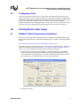
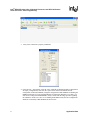
Intel® IXP42X Product Line of
Network Processors and IXC1100
Control Plane Processor: Flash
Programming
Application Note
October 2004
Document Number: 254273-002
Intel® IXP42X Product Line of Network Processors and IXC1100 Control
Plane Processor: Flash Programming
INFORMATION IN THIS DOCUMENT IS PROVIDED IN CONNECTION WITH INTEL® PRODUCTS. NO LICENSE, EXPRESS OR IMPLIED, BY
ESTOPPEL OR OTHERWISE, TO ANY INTELLECTUAL PROPERTY RIGHTS IS GRANTED BY THIS DOCUMENT. EXCEPT AS PROVIDED IN
INTEL'S TERMS AND CONDITIONS OF SALE FOR SUCH PRODUCTS, INTEL ASSUMES NO LIABILITY WHATSOEVER, AND INTEL DISCLAIMS
ANY EXPRESS OR IMPLIED WARRANTY, RELATING TO SALE AND/OR USE OF INTEL PRODUCTS INCLUDING LIABILITY OR WARRANTIES
RELATING TO FITNESS FOR A PARTICULAR PURPOSE, MERCHANTABILITY, OR INFRINGEMENT OF ANY PATENT, COPYRIGHT OR OTHER
INTELLECTUAL PROPERTY RIGHT. Intel products are not intended for use in medical, life saving, life sustaining applications.
Intel may make changes to specifications and product descriptions at any time, without notice.
Designers must not rely on the absence or characteristics of any features or instructions marked “reserved” or “undefined.” Intel reserves these for
future definition and shall have no responsibility whatsoever for conflicts or incompatibilities arising from future changes to them.
Contact your local Intel sales office or your distributor to obtain the latest specifications and before placing your product order.
Copies of documents which have an ordering number and are referenced in this document, or other Intel literature may be obtained by calling
1-800-548-4725 or by visiting Intel's website at http://www.intel.com.
BunnyPeople, Celeron, Chips, Dialogic, EtherExpress, ETOX, FlashFile, i386, i486, i960, iCOMP, InstantIP, Intel, Intel Centrino, Intel Centrino logo,
Intel logo, Intel386, Intel486, Intel740, IntelDX2, IntelDX4, IntelSX2, Intel Inside, Intel Inside logo, Intel NetBurst, Intel NetMerge, Intel NetStructure,
Intel SingleDriver, Intel SpeedStep, Intel StrataFlash, Intel Xeon, Intel XScale, IPLink, Itanium, MCS, MMX, MMX logo, Optimizer logo, OverDrive,
Paragon, PDCharm, Pentium, Pentium II Xeon, Pentium III Xeon, Performance at Your Command, Sound Mark, The Computer Inside., The Journey
Inside, VTune, and Xircom are trademarks or registered trademarks of Intel Corporation or its subsidiaries in the United States and other countries.
*Other names and brands may be claimed as the property of others.
Copyright © Intel Corporation, 2004
2
Application Note
Intel® IXP42X Product Line of Network Processors and IXC1100 Control
Plane Processor: Flash Programming
Contents
1.0
Introduction.................................................................................................................................... 1
1.1
1.2
2.0
Scope of this Document........................................................................................................ 1
Related Documents and Web Sites ...................................................................................... 1
Flash Programmers...................................................................................................................... 2
2.1
2.2
3.0
JTAG Interface...................................................................................................................... 2
Host Interface ....................................................................................................................... 2
Flash Programming — A Brief Overview .................................................................................... 2
3.1
3.2
4.0
Script Files ............................................................................................................................ 2
Configuration Files ................................................................................................................ 3
Flashing Boot Loader Image ........................................................................................................ 3
4.1
5.0
RedBoot* Flash Programming Using Raven* ....................................................................... 3
Swapping the Bootloader Images................................................................................................7
5.1
5.2
Swapping-Out Bootloaders ................................................................................................... 9
5.1.1 Swapping to the OpenRG* RG Bootloader.............................................................. 9
5.1.1.1 Downloading the Bootloader .................................................................... 9
5.1.1.2 Copying the Image to the Boot-Flash Location ........................................ 9
5.1.2 Swapping to the RedBoot* Bootloader .................................................................. 10
5.1.3 Programming the RedBoot* Image over visionICE* .............................................. 11
Loading the Images ............................................................................................................ 11
5.2.1 Programming LSP and iGateway* Images into Flash............................................ 11
5.2.2 Ethernet Download ................................................................................................ 11
5.2.3 Serial Download..................................................................................................... 12
5.2.4 Programming OpenRG* Image into Flash ............................................................. 12
6.0
Summary ...................................................................................................................................... 13
A
.s19 File Handling ........................................................................................................................ 15
A.1
A.2
Saving the Contents of a Flash to .s19 File Format............................................................ 15
Programming the Flash from the Saved .s19 File .............................................................. 17
Tables
1
2
Related Information/Web Sites ..................................................................................................... 1
Intel® IXP425 Network Processor: Memory Map.......................................................................... 8
Revision History
Date
Revision
September 2004
002
Updated product branding.
February 2004
001
Initial release.
Application Note
Description
3
Intel® IXP42X Product Line of Network Processors and IXC1100 Control
Plane Processor: Flash Programming
This page is intentionally left blank.
4
Application Note
Intel® IXP42X Product Line of Network Processors and IXC1100 Control
Plane Processor: Flash Programming
1.0
Introduction
The IXP42X product line supports interfacing flash memory in its Expansion bus. This document
discusses flash programming using the Joint Test Action Group (JTAG) interface, and discusses
swapping-out the bootloaders and loading the flash image.
Discussion involving specific flash programmers is for illustration purposes only; recommendation
of any particular flash programmer is not intended.
1.1
Scope of this Document
This document is intended for system developers using the IXP42X product line. Step-by-step
instructions are provided to:
1. Program a (blank) flash device with a binary image (typically downloaded from Intel’s Web
site).
2. Swap-out the bootloaders and load the flash image.
3. Save the contents of a flash in a .s19 file format.
4. Program a flash device with the contents of the (saved) .s19 file.
For illustration purposes, the Intel® IXDP425 / IXCDP1100 Development Platform and Coyote*
Gateway Reference Design are used.
This document is not intended to cover JTAG implementation in detail, compare flash
programmers, or provide endianness and byte-swap specifics; however, Table 1 provides links to
such information.
1.2
Related Documents and Web Sites
Table 1.
Related Information/Web Sites
Description
Web Site Link
IXP42X product line of Network Processors and IXC1100
Control Plane Processor: Understanding Big and Little
Endian Modes Application Note
http://www.intel.com/design/network/applnots/
254237.htm
Intel XScale® Microarchitecture for the PXA255
Processor User Manual (Soft Debug chapter)
http://www.intel.com/design/pca/
applicationsprocessors/manuals/278796.htm
The ZEN of BDM, Macraigor Systems* Inc.
http://www.ocdemon.net/zenofbdm.pdf
Macraigor Systems Inc. software
http://www.ocdemon.net/Merchant2/
merchant.mv?Screen=CTGY&Store_Code=MTS&
Category_Code=Software
Green Hills Software*
http://www.ghs.com
Wind River*
http://www.windriver.com
File format/programming information
http://www.wotsit.org
Application Note
1
Intel® IXP42X Product Line of Network Processors and IXC1100 Control
Plane Processor: Flash Programming
2.0
Flash Programmers
2.1
JTAG Interface
The IXDP425 / IXCDP1100 platform has a JTAG receptacle on its base board. JTAG flash
programmers have two interfaces:
1. JTAG interface, which connects to the IXDP425 JTAG receptacle.
2. a host interface, typically connected to a PC that runs the flash programming software.
Note:
You must ensure that your system board has a JTAG connector that is mechanically and electrically
compatible with your chosen flash programmer.
Caution:
Also be sure to NOT reverse the connector; reversing the connector may lead to electrical damage.
It is also advisable to simultaneously power on both the flash programmer and the target system
board.
2.2
Host Interface
Flash programmers vary in price and performance and are available for different host interfaces.
Cost-effective JTAG flash programmers employ the parallel port for the host interface whereas
higher-performance programmers use Ethernet as the host interface.
In this application note, the parallel port is used for the host interface. The parallel port can operate
in multiple modes, the most common of which are ECP and EPP. The JTAG flash programmers
generally require the parallel port to be configured in EPP mode — not in ECP mode.
3.0
Flash Programming — A Brief Overview
‘Transparent’ to the user — and through the JTAG interface — flash programmers download
software-debug code directly into the IXP42X product line Intel XScale core instruction cache.
This downloaded code, executing on the IXDP425 / IXCDP1100 platform, handshakes and begins
communicating with the flash programming software executing on the host (for further details,
please see the “Software Debug” chapter in the Intel XScale® Microarchitecture for the PXA255
Processor User Manual).
3.1
Script Files
The target board has devices that need to be initialized to function properly. For cases where flash
programmer software uses these devices (for example, when relying on SDRAM functioning), the
flash programmer uses script files specific to the platform. The script files contain the initialization
sequences executed to initialize these devices, and developers can adopt and modify these scripts
as needed.
In cases where flash programmer software does not use board-specific devices (for example, only
uses on-chip cache and does not rely on SDRAM functioning), then the flash programmer does not
use the initialization scripts.
2
Application Note
Intel® IXP42X Product Line of Network Processors and IXC1100 Control
Plane Processor: Flash Programming
3.2
Configuration Files
Similar to initialization scripts specific to a target board, many flash programmers have boardspecific configuration files for storing parameters such as flash start/end addresses, SDRAM start/
end addresses, and endianness. When using the flash programmer with a particular board, the user
can select the appropriate configuration file (for example, one specific to the IXDP425 /
IXCDP1100 platform). Some flash programmers provide a GUI to select these parameters, which
can then be saved in a configuration file; board developers can create their own custom file.
4.0
Flashing Boot Loader Image
4.1
RedBoot* Flash Programming Using Raven*
This section provides step-by-step instructions and screen captures for flash programming using
Raven from Macraigor Systems. The Red Hat* RedBoot image is available via the following Intel
Web site:
http://www.intel.com/design/network/products/npfamily/ixp425swr1.htm
If the flash is not blank, and you intend to save its contents prior to flashing the device with the new
image, then follow the steps listed in Appendix A, “Saving the Contents of a Flash to .s19 File
Format” to save the existing image and then follow the instructions listed here:
1. Connect the Raven JTAG cable to the IXDP425 / IXCDP1100 platform (or your IXP42X
product line–based target board). Simultaneously power up both the board and the Raven.
Connect the Raven to the parallel port and set up the communication method for the parallel
port (shown below). Set up the parallel port in your host for EPP mode.
2. Start the test software.
Application Note
3
Intel® IXP42X Product Line of Network Processors and IXC1100 Control
Plane Processor: Flash Programming
3. Verify if the connection is properly established.
4. Using the File -> Open Menu, select the xscale_richfield.ocd flash programmer configuration
file (open_configurations), then click the “open” button. Please note that the default
configuration is LITTLE ENDIAN; change the configuration to BIG ENDIAN for flashing the
RedBoot bootloader. If you are flashing EBOOT (for Microsoft* Windows* CE .NET), you
don’t need to change the ENDIANNESS. Always consult with the image provider regarding
the endianness. In this case, since we are flashing the RedBoot loader, the CPU configuration
should be set manually to BIG ENDIAN as shown below.
4
Application Note
Intel® IXP42X Product Line of Network Processors and IXC1100 Control
Plane Processor: Flash Programming
5. Byte-swap the image by running a byteswap utility (available via the Web). Please note that
the byteswap utility may require input and output file names to be unique and may not allow
special characters in the file name. (In general, the release notes/documentation accompanying
the image will mention if byte swapping is needed or not.)
6. Run the BinToS19 utility for converting to the .s19 format required by the flash programmer.
Please note below that 0x50000000 is the starting address of the flash device in the IXDP425 /
IXCDP1100 platform.
7. Now that the connection is verified, the image is byte-swapped and converted to the
appropriate (.s19) format, the programmer is configured with a correct configuration file and
updated for this particular flashing to be BIG ENDIAN, and the next step is to program the
flash. You can choose the Erase option to erase prior to programming as shown below. Click
the Program button. Wait for the progress bar to go through Erase followed by Program /Verify
operation (not shown here).
Application Note
5
Intel® IXP42X Product Line of Network Processors and IXC1100 Control
Plane Processor: Flash Programming
8. Wait for the progress bar to finish the Erase. The following screens show stages of completion
of the Programming/Verifying operation.
a. The Programming/Verifying operation in progress:
6
Application Note
Intel® IXP42X Product Line of Network Processors and IXC1100 Control
Plane Processor: Flash Programming
b. The Programming/Verifying operation completing:
5.0
Swapping the Bootloader Images
This section discusses how to change the image that is loaded into the flash.
Below is the memory map of the for reference. The IXP425 network processor implements a single
address map that is used for all internal memory and register space; see Table 2.
Application Note
7
Intel® IXP42X Product Line of Network Processors and IXC1100 Control
Plane Processor: Flash Programming
Table 2.
Intel® IXP425 Network Processor: Memory Map
Start Address
End Address
Size
Description
0000_0000
0FFF_FFFF
256 Mbyte
0000_0000
3FFF_FFFF
1 Gbyte
4000_0000
47FF_FFFF
128 Mbyte
(Reserved)
4800_0000
4FFF_FFFF
128 Mbyte
PCI data
5000_0000
5FFF_FFFF
256 Mbyte
Expansion-bus data
6000_0000
63FF_FFFF
64 Mbyte
Queue manager
6400_0000
BFFF_FFFF
C000_0000
C000_00FF
C000_0100
C3FF_FFFF
C400_0000
C400_00FF
C400_0100
C7FF_FFFF
C800_0000
C800_0FFF
1 Kbyte
Fast UART
C800_1000
C800_1FFF
1 Kbyte
Console UART
C800_2000
C800_2FFF
1 Kbyte
Internal Bus Performance Monitoring Unit (PMU)
C800_3000
C800_3FFF
1 Kbyte
Interrupt controller
C800_4000
C800_4FFF
1 Kbyte
GPIO controller
C800_5000
C800_5FFF
1 Kbyte
Timers
C800_6000
C800_6FFF
1 Kbyte
WAN/HSS NPE — Not user-programmable
C800_7000
C800_7FFF
1 Kbyte
Ethernet NPE A — Not user-programmable
C800_8000
C800_8FFF
1 Kbyte
Ethernet NPE B — Not user-programmable
Expansion-bus data
SDRAM data
(Reserved)
256 byte
PCI configuration registers
256 byte
Expansion-bus configuration registers
(Reserved)
(Reserved)
C800_9000
C800_9FFF
1 Kbyte
Ethernet MAC A (ETH-0)
C800_A000
C800_AFFF
1 Kbyte
Ethernet MAC B (ETH-1)
C800_B000
C800_BFFF
1 Kbyte
USB controller
C800_C000
C800_FFFF
(Reserved)
C801_0000
CBFF_FFFF
CC00_0000
CC00_00FF
(Reserved)
CC00_0100
CEFF_FFFF
(Reserved)
D000_0000
FFFF_FFFF
(Reserved)
256 byte
SDRAM configuration registers
If you are swapping-out the LSP or iGateway* image for the Jungo* OpenRG* image, you first
must swap-out the bootloaders; this is because the OpenRG image currently works with a
proprietary bootloader: RG Loader*.
For that reason, the following sections discuss:
• Swapping-out the bootloader
• Loading the flash image
8
Application Note
Intel® IXP42X Product Line of Network Processors and IXC1100 Control
Plane Processor: Flash Programming
5.1
Swapping-Out Bootloaders
Please note that this section pertains to the Coyote* Gateway Reference Design.
5.1.1
Swapping to the OpenRG* RG Bootloader
There are two basic steps to this procedure:
1. Downloading the bootloader.
2. Copying the image to the boot-flash location.
5.1.1.1
Downloading the Bootloader
This procedure can be executed via a serial interface or an Ethernet download.
If downloading the bootloader through a serial interface:
1. Display the RedBoot prompt.
2. Start an x-modem transfer of the zImage file in your COM program, by typing the following
command:
RedBoot> load -r -b 0x11400000 -m x
This command copies the image from your host PC to the beginning of SDRAM location
0x11400000.
3. Proceed to the procedure for copying the image to the boot-flash location.
If downloading the bootloader through an Ethernet download:
1. Install a PCI EtherPRO* card by first inserting the miniPCI adapter installed in the Coyote
gateway platform.
2. Insert the PCI NIC into the miniPCI adapter — ensuring that the Ethernet port faces inwards.
3. Power on Coyote gateway platform.
4. At the RedBoot prompt, use the fconfig command to assign an IP address to your EtherPRO
card.
5. Type the following command:
RedBoot> load -r rgloader.img -b 0x11400000
6. Proceed to the procedure for copying the image to the boot-flash location.
5.1.1.2
Copying the Image to the Boot-Flash Location
After either of the preceding download procedures, copy the image to the boot-flash location using
the following steps:
1. Display the RedBoot prompt.
2. Type the following command at the RedBoot prompt:
RedBoot> fis create rgloader -f 0x50000000 -b 0x11400000 -l 0x100000
Application Note
9
Intel® IXP42X Product Line of Network Processors and IXC1100 Control
Plane Processor: Flash Programming
This command copies the image rgloader — 1 Mbyte in size — from the beginning of SDRAM
location 0x11400000 to the beginning of the flash address location at 0x500000000.
3. Reset the board.
The board boots up with an RG bootloader prompt.
5.1.2
Swapping to the RedBoot* Bootloader
To download the RedBoot bootloader from the RG Bootloader:
1. Reset the Coyote gateway platform.
2. During the reset, stop the auto-boot process and display the RG Bootloader prompt by
pressing [Esc].
3. Connect your Ethernet interface on the PC to the IXP0 Ethernet interface on the Coyote
gateway platform.
The RG Bootloader supports image download over the IXP425 network processor LAN Ethernet
NPE.
4. Configure your PC IP address to be on the same subnet as your IXP0 interface:
• The default address for the IXP0 interface is:
192.168.1.10
• You can configure your PC IP address to:
192.168.1.20
It also is possible to change the RG Bootloader IP through the ifconfig command. If using this
technique:
• Ensure that you are familiar with the procedure.
• If using the Microsoft Windows operating system, ensure that the TFTP server has a TFTP
directory.
To change the loader’s IP:
1. Ensure that there is a working TFTP server on your PC.
2. Place the image to be burned (flash.img) into one of the following directories on the PC:
• /tftpboot
• Any directory that the PC uses to set the server
3. Download the unswapped RedBoot image into the Coyote gateway platform flash from the
PC. To execute, type the following command:
OpenRG boot> load -u tftp://192.168.1.10/redboot.bin -r 0
If successful, a download-complete message appears. The download process takes about three to
five minutes.
4. Verify that the new image has been created. To execute, type the following command:
OpenRG boot> flash_layout
10
Application Note
Intel® IXP42X Product Line of Network Processors and IXC1100 Control
Plane Processor: Flash Programming
5. Verify that Section 2 of the flash layout is initialized with an OpenRG image and Section 4 of
the flash layout is initialized with factory settings.
6. Delete the old configuration files. To execute, type the following command:
OpenRG boot> flash_erase 5
OpenRG boot> flash_erase 6
7. Hard-reset the board and allow RG Loader to load the RedBoot loader.
5.1.3
Programming the RedBoot* Image over visionICE*
To load the RedBoot image for the very first time:
1. If not already displayed, access the Windows command prompt.
2. Convert image.redboot to a flat bin image, using the visionICE command utility. To do this,
type the following commands:
cd c:\estii
convert -s image.redboot -a binimage.bin
3. On the Coyote gateway platform, connect the J15 connector to the visionICE device JTAG
interface.
4. Burn the RedBoot image using a visionICE device.
5. Hard-reset the Coyote gateway platform.
5.2
Loading the Images
5.2.1
Programming LSP and iGateway* Images into Flash
Coyote gateway platform images may be loaded to flash by either of the following methods:
• Ethernet download
• Serial download
5.2.2
Ethernet Download
The Coyote gateway platform demo images must reside in the default directory of the TFTP server
on your server PC. In order to use the following procedure, you must:
• Have an Intel EEPRO100 Ethernet PCI card in one of the PCI slots
• Connect the PCI card with a host PC that has loaded the image
To perform an Ethernet download:
1. Launch your TFTP-server application.
2. In the RedBoot shell, execute fconfig.
3. Configure the IP addresses for the Coyote gateway platform and the remote server where the
image resides.
Application Note
11
Intel® IXP42X Product Line of Network Processors and IXC1100 Control
Plane Processor: Flash Programming
4. Reset the board and confirm that RedBoot has found the Ethernet card and the IP addresses
that you assigned.
5. This information will appear in the RedBoot startup message.
6. Load the platform’s demo images to the flash by using the following commands at the
RedBoot prompt:
RedBoot> load -r LSP -b 0x11400000
Redboot> fis create LSP -f 0x50940000 -b 0x11400000 -l 0x300000
RedBoot> load -r iGateway -b 0x11400000
Redboot> fis create iGateway -f 0x5004000 -b 0x11400000 -l
0x900000
5.2.3
Serial Download
To perform a serial download:
1. Start an x-modem transfer of the zImage file in your COM program by typing the following
command at the RedBoot prompt:
RedBoot> load -r -b 0x11400000 -m x
2. Start an x-modem transfer of the Image file in your COM program.
5.2.4
Programming OpenRG* Image into Flash
1. Power up the Coyote gateway platform.
The RG Loader greeting will appear on the serial modem console screen.
2. Connect your Ethernet interface on the PC to the IXP0 Ethernet interface on the board.
The RG Bootloader supports image downloads over the IXP425 network processor LAN Ethernet
NPE.
3. Configure your PC IP address to be on the same subnet as your IXP0 interface.
• The default address for the IXP0 interface is:
192.168.1.10
• You can configure your PC IP address to:
192.168.1.20
It also is possible to change the RGLoader IP through the ifconfig command. If using this
technique:
• Ensure that you are familiar with the procedure
• If using the Windows operating system, ensure that the TFTP server has a TFTP directory
To change the loader’s IP:
1. Ensure that there is a working TFTP server on your PC.
2. Place the image to be burned (flash.img) into one of the following directories on the PC:
• /tftpboot
12
Application Note
Intel® IXP42X Product Line of Network Processors and IXC1100 Control
Plane Processor: Flash Programming
• Any directory that the PC uses to set the server
3. Download the new image into the board's flash from the PC by typing the following command:
OpenRG boot> load -u tftp://192.168.1.10/flash.img -r 0
If this step is successful, a download-complete message appears. The download may take about
three to five minutes.
4. Verify that the new image has been created. To execute, type the following command:
OpenRG boot> flash_layout
5. Verify that Section 2 of the flash layout is initialized with an OpenRG image and that Section 4
of the flash layout is initialized with factory settings.
6. Delete the old configuration files. To execute, type the following commands:
OpenRG boot> flash_erase 5
OpenRG boot> flash_erase 6
7. Hard-reset the board and allow RGLoader to load the OpenRG image.
Note:
It is important to hard-reset the board and not use the reboot command; using the command will
cause the old configuration files to be burned back to the flash and may cause problems in loading
the new image.
The RG Bootloader auto-loads the RG image in about three seconds.
6.0
Summary
The above sections cover various aspects of flash programming using the JTAG interface in a
IXDP425 / IXCDP1100 platform (or IXP42X product line–based target board).
Application Note
13
Intel® IXP42X Product Line of Network Processors and IXC1100 Control Plane
Processor: Flash Programming
This page is intentionally left blank.
14
Application Note
Intel® IXP42X Product Line of Network Processors and IXC1100 Control
Plane Processor: Flash Programming
Appendix A .s19 File Handling
A.1
Saving the Contents of a Flash to .s19 File Format
1. After choosing the IXDP425 (xscale_richfield as shown below) option, select upload flash
option . Please note that in the case of saving a file (for future flashing purposes), leave the
endianness to default to “LITTLE ENDIAN”.
2. Select the file name to save the image to in the required format (in the following screen, the
.s19 format is chosen).
Application Note
15
Intel® IXP42X Product Line of Network Processors and IXC1100 Control
Plane Processor: Flash Programming
3. Provide the start and end address of the flash device; refer to the flash tab of the flash
programmer menu to determine the end address from the last sector address and the size of the
sector.
4. Enter the start address and end address of the flash.
16
Application Note
Intel® IXP42X Product Line of Network Processors and IXC1100 Control
Plane Processor: Flash Programming
5. Select Upload and wait until it successfully completes.
A.2
Programming the Flash from the Saved .s19 File
1. Select the Program File option.
Application Note
17
Intel® IXP42X Product Line of Network Processors and IXC1100 Control
Plane Processor: Flash Programming
2. Note that the start and end address automatically loaded from the .s19 file.
3. The flash gets erased. The following screens show stages of completion of the Programming/
Verifying operation.
18
Application Note
Intel® IXP42X Product Line of Network Processors and IXC1100 Control
Plane Processor: Flash Programming
a. The Programming/Verifying operation in progress:
b. The Programming/Verifying operation completing:
Application Note
19
Intel® IXP42X Product Line of Network Processors and IXC1100 Control
Plane Processor: Flash Programming
20
Application Note