1
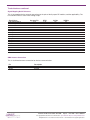
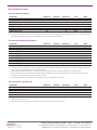
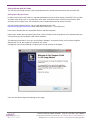
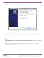
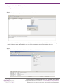
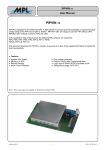
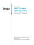
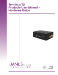
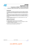
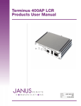
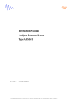
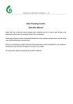
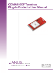
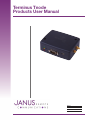
Terminus Tnode
Products User Manual
Bulletin
Revision
Date
JA18-UM
A00
08 Oct 2014
TABLE OF CONTENTS
TABLE OF CONTENTS and DISCLAIMER.............................................................................................................................. 2
Tnode General Description..................................................................................................................................................... 3
Block Diagram......................................................................................................................................................................... 3
Tnode User Interfaces......................................................................................................................................................... 4-6
USB
RS232
30P Header Access
DIP Selector
Reset
LED Indicators
Signal Mapping Quick Reference
Antenna Connection
Electrical Specifications...................................................................................................................................................... 7-9
Getting Started with the Tnode....................................................................................................................................... 10-14
Setting up Synapse Portal
Connecting to the Tnode
Ordering Information............................................................................................................................................................. 15
Revision History.................................................................................................................................................................... 15
DISCLAIMER
The information contained in this document is the proprietary information of Connor-Winfield Corporation and its affiliates (Janus Remote Communication). The contents are confidential and any disclosure to
persons other than the officers, employees, agents or subcontractors of the owner or licensee of this document, without the prior written consent of Connor-Winfield, is strictly prohibited. Connor-Winfield
makes every effort to ensure the quality of the information it makes available. Notwithstanding the foregoing, Connor-Winfield does not make any warranty as to the information contained herein, and does
not accept any liability for any injury, loss or damage of any kind incurred by use of or reliance upon the information. Connor-Winfield disclaims any and all responsibility for the application of the devices
characterized in this document, and notes that the application of the device must comply with the safety standards of the applicable country, and where applicable, with the relevant wiring rules. ConnorWinfield reserves the right to make modifications, additions and deletions to this document due to typographical errors, inaccurate information, or improvements to programs and/or equipment at any time and
without notice. Such changes will, nevertheless be incorporated into new editions of this application note.
All rights reserved 2011 Connor-Winfield Corporation
Terminus Tnode User Guide JA18-UM
Page 2
Rev: A00
Date: 10/08/14
© Copyright 2014 Janus Remote Communications Specifications subject to change without notice
All Rights Reserved See website for latest revision.
Not intended for life support applications.
Tnode Terminus General Description
The Terminus Tnode is a communication control terminal with a compact, rugged enclosure that encapsulates
everything needed for short range M2M capabilities. The two orderable frequency types allow for system deployment
in different networks with little change in design or investment.
Powered by the Synapse RF engine, the Tnode contains all circuitry required to operate in 2.4Ghz or 915Mhz
frequency ranges. It can receive power from a 12v wall wart or a 5v mini USB connection, contains a serial RS-232
for programming and debugging, and has discrete and analog inputs for monitoring.
Figure 1: Tnode 2.4 GHz Block diagram, denotes external connections and internal routing
Figure 1: Tnode 915 MHz Block diagram, denotes external connections and internal routing
Terminus Tnode User Guide JA18-UM
Page 3
Rev: A00
Date: 10/08/14
© Copyright 2014 Janus Remote Communications Specifications subject to change without notice
All Rights Reserved See website for latest revision.
Not intended for life support applications.
Tnode Interfaces:
DC Power jack
The 2.1mm center conductor power jack accepts input voltages from 6 to 60VDC.
Pin
Description
Center Pin
Outer Conductor
Supply (+)
Supply (-)
Supply power can also be applied to the unit through the 30 Pin locking header.
USB
The Mini AB USB connector is an alternate power supply connection. It accepts input voltages from 4.75 to 5.5v.
Pin
1
2
3
4
5
Name
VBUS
N/C
N/C
N/C
GND
RS232
The DB9 port follows the standard for RS-232 communications and gives the connections for serial interaction with
hardware handshaking. It is, however, pinned as the DCE (host) since the application running abilities make the
Tnode an autonomous unit that can control external components. Hardware flow control is not available.
Pin
Description
Direction
2
3
5
1, 4, 6, 7, 8, 9
RXD
TXD
GND
N/C
Input
Output
Supply
-
Reset
The reset button is connected to the reset pin of the Synapse RF module. The reset signal, broken out to the 30P
header must be controlled via open collector only, do not use a pull up on this signal.
Input Logic State
Description
HIGH-Z
0
Active State
Reset State
LED Indicators
GPIO controlled LED stack. These are application controlled, by default they are OFF. Drive the noted GPIO HIGH to
activate the respective LED.
LED Color
Description
Red
Yellow
Green
Synapse GPIO18
Synapse GPIO9
Synapse GPIO10
Terminus Tnode User Guide JA18-UM
Page 4
Rev: A00
Date: 10/08/14
© Copyright 2014 Janus Remote Communications Specifications subject to change without notice
All Rights Reserved See website for latest revision.
Not intended for life support applications.
Tnode Interfaces continued
30P Header Access
The Tnode’s header gives access to many signals not available through standardized connectors. It uses a Samtec
polar and locking connector that allows the user to create their own harness to suit the application.
Pin
Description
1
2
3
5
6
7
8
9
10
13
14
15
16
18
19
20
21
22
23
24
25
26
29
30
4, 11, 12, 17, 27, 28
Reset
Power Supply Input
N/C
N/C
N/C
RS232 RX
RX232 TX
N/C
N/C
Low Voltage ADC A
O/C Input E
Low Voltage ADC B
O/C Input A
O/C Input B
O/C Input D
O/C Input C
N/C
N/C
Synapse GPIO 14
Synapse GPIO 13
Synapse GPIO 12
N/C
0-10V ADC B
0-10V ADC A
Supply Ground
Samtec Part Number:
Housing:
IPD1-15-D-K
Janus Store Part Number:
Housing:
XT-507-G
Direction
Input
Supply
Input
Output
Input
Input
Input
Input
Input
Input
Input
Bidirectional
Bidirectional
Bidirectional
Input
Input
N/A
Contacts:
CC79L-2024-01-L
Contacts:
XT-479-G
Terminus Tnode User Guide JA18-UM
Page 5
Rev: A00
Date: 10/08/14
© Copyright 2014 Janus Remote Communications Specifications subject to change without notice
All Rights Reserved See website for latest revision.
Not intended for life support applications.
Tnode Interfaces continued
Signal Mapping Quick Reference
This is the mapping for the external connections to the pins of the Synapse RF modules, and the applicability. The
Pin and GPIO value is useful when writing scripts.
Signal Name
Low Voltage ADC A
Low Voltage ADC B
0-10V ADC A
0-10V ADC B
O/C Input A
O/C Input B
O/C Input C
O/C Input D
O/C Input E
Synapse GPIO 14
Synapse GPIO 13
Synapse GPIO 12
Red LED
Yellow LED
Green LED
UART RX
UART TX
Synapse Pin
GPIO
2.4Ghz
915Mhz
7, 18
8, 19
17
13
2
3
4
5
6
16
15
14
20
11
12
9
10
5, 16
6, 17
15
11
0
1
2
3
4
14
13
12
18
9
10
7
8
Yes
Yes
Yes
Yes
Yes
Yes
Yes
Yes
Yes
Yes
Yes
Yes
Yes
Yes
Yes
Yes
Yes
Yes
Yes
Yes
No
Yes
Yes
Yes
Yes
Yes
No
No
No
Yes
Yes
Yes
Yes
Yes
SMA Antenna Connection
This is a bulkhead antenna connection for wireless communication.
Pin
Description
Center Pin
Shield
Signal
Ground
Terminus Tnode User Guide JA18-UM
Page 6
Rev: A00
Date: 10/08/14
© Copyright 2014 Janus Remote Communications Specifications subject to change without notice
All Rights Reserved See website for latest revision.
Not intended for life support applications.
Electrical Specifications
Absolute Maximum Ratings:
Parameter
Minimum
Nominal
Maximum
Unit
Note
Operating Temperature
Supply (Supply & Enable Input)
VIN (GPIO)
VIN (Open Collector Input)
VIN (0-10V ADC)
VIN (Low Voltage ADC)
VIN (RS-232 Inputs)
-40
6
0
0
0
0
-25
-
-
-
-
-
-
-
85
76
3.6
3.6
10.5
3.6
25
°C
Volts
Volts
Volts
Volts
Volts
Volts
1
1,2
1
1
1
1
Notes:
1) Operation of the device at these or any other conditions beyond those listed under Recommended Operating Conditions is not implied. Exposure to
Absolute Maximum Rating conditions for extended periods of time may affect device reliability.
Recommended Operating Conditions:
Parameter
Minimum
Operational Temperature
-30
2.1mm Barrel Jack Supply
7
• Peak Supply Current
93
• Average Supply Current
Mini USB Jack
4.7
• Peak Supply Current
109
• Average Supply Current
-
Lithium Ion Battery
-
• Peak Supply Current
-
• Average Supply Current
-
Nominal
Maximum
Unit
-
12
-
-
5
-
-
3.7
112
28
80
28
-
23
5.5
-
27
-
-
-
°C
Volts
mA
mA
Volts
mA
mA
Volts
mA
mA
Note
1,4
2,4
1,4
2,4
3,4
3,4
Notes:
1) Peak Supply Current specification is stated as the minimum amount of current the external power supply must be capable of supplying during the
TX burst of the embedded radio across the rated input voltages.
2) Average Supply Current specification is stated as the maximum average current the Tnode should draw across the rated voltages.
3) Peak current draw noted for operating via the internal battery pack during the Tx burst of the embedded radio. Average current draw noted for
operating via the internal battery pack during an idle/Rx condition.
4) Peak and average draws noted while RS-232 is operating and active and the GPIO are in idle state.
I/O Levels (GPIO – 915Mhz only)
Parameter
Minimum
Input Voltage Low - Vil
Input Voltage High - Vih
2.7
Output Voltage Low – Vol
-
Output Voltage High – Voh
2.6
Output Current - Io
-
Nominal
Maximum
-
0.6
-
-
0.6
-
-
-
8
Unit
Volts
Volts
Volts
Volts
mA
Note
1
1
Notes:
1) All typical specifications for 25°C
2) These go directly to the Synapse radio, consult the Synapse RF300 datasheet for more information.
Terminus Tnode User Guide JA18-UM
Page 7
Rev: A00
Date: 10/08/14
© Copyright 2014 Janus Remote Communications Specifications subject to change without notice
All Rights Reserved See website for latest revision.
Not intended for life support applications.
Electrical Specifications
I/O Levels (O/C Input)
Parameter
Minimum
Nominal
Maximum
Unit
Note
Output Voltage Low – Vol
Output Voltage High – Voh
Rpu - Pull Up Resistance
Output Current - Io
-
2.7
-
-
-
3.3
10k
-
0.1
-
-
0.9
Volts
Volts
Ohms
mA
1,2
1,2
2
1,2
Notes:
1) All typical specifications for 25°C
2) These connections are designed with a clamped, PNP based isolation stage. They should ONLY be controlled via open collector. Do not put a pull
up on these signals, there is already one tied to 3.3v.
I/O Levels (0-10V ADC)
Parameter
Minimum
Nominal
Maximum
Unit
Pin Input Voltage – 2.4Ghz
0
-
10
Volts
ADC Range
0
-
1.8
Volts
Load Resistance
-
5.3k
-
Ohms
Input Scaling
-
0.188
-
Pin Input Voltage – 915Mhz
0
10
Volts
ADC Range
0
3.3
Volts
Load Resistance
-
3.0k
-
Ohms
Input Scaling
-
0.33
-
Conversion Resolution
10
Bits
Note
1
3
2
3
Notes:
1) The 2.4Ghz variant voltage reference is a programmable 1.5v, 1.6v, or 1.8v.
2) The 915Mhz variant voltage reference is an internal 1.65v source, or selectable to use an external reference (3.3v). Consult the Synapse RF300
manual for doing so.
3) To ensure the full 10v range can be used for various sensors, we scale the input voltage to a safe level. (E.G. 8v * 0.188 = 1.504v ADC input).
I/O Levels (Low Voltage ADC)
Parameter
Minimum
Nominal
Maximum
Pin Input Voltage – 2.4Ghz
0
-
3.3
ADC Range
0
-
1.8
Load Resistance
-
150
-
Pin Input Voltage – 915Mhz
0
3.3
ADC Range
0
3.3
Load Resistance
-
150
-
Conversion Resolution
10
Unit
Note
Volts
Volts
Ohms
Volts
Volts
Ohms
Bits
1
1
3
2
2
3
Notes:
1) The 2.4Ghz variant voltage reference is a programmable 1.5v, 1.6v, or 1.8v. The I/O is tolerant of 3.3v but the ADC will not read above 1.8v.
2) The 915Mhz variant voltage reference is an internal 1.65v source, or selectable to use an external reference (3.3v). Consult the Synapse RF300
manual for doing so.
3) Keep note of the increased load of the LV ADC section. If your sensor cannot source this, an inline resistor may be needed.
Terminus Tnode User Guide JA18-UM
Page 8
Rev: A00
Date: 10/08/14
© Copyright 2014 Janus Remote Communications Specifications subject to change without notice
All Rights Reserved See website for latest revision.
Not intended for life support applications.
Electrical Specifications
Radio RF Specifications (2.4Ghz)
Parameter
Radio Name
Outdoor LoS Range
Transmit Power
Data Rates
Receiver Sensitivity
Modulation
Number of Channels
Agency Approvals
RF200PD1
3 Miles @ 250Kbps
15dBm
250Kbps
500Kbps
1Mbps
2Mbps
-103dBm (1%PER)
Q-QPSK
16
FCC ID: U9O-RF200
IC: 7084A-RF200
RF Antenna (2.4Ghz)
Parameter
Connector Type
Impedance
Approved FCC/IC Antenna
Type
Gain
Application
Min. Separation
RP-SMA
50 Ohms
Pulse W1027
Dipole (quarter-wave RPSMA)
3.2 dBi
Fixed/Mobile
20 Centimeters
Radio RF Specifications (915 Mhz)
Parameter
Radio Name
Outdoor LoS Range
Transmit Power
Data Rates
Receiver Sensitivity
Modulation
Number of Channels
Agency Approvals
RF300PD1
3 Miles @ 150Kbps
20dBm
150Kbps
-99dBm (1%PER)
GFSK
16
FCC ID: U9O-RF300
IC: 7084A-RF300
RF Antenna (915 Mhz)
Parameter
Connector Type
Impedance
Approved FCC/IC Antenna
Type
Gain
Application
Min. Separation
RP-SMA
50 Ohms
Linx ANT-916-CW-RCL
Dipole (quarter-wave RPSMA)
0.47dbi
Fixed/Mobile
20 Centimeters
Terminus Tnode User Guide JA18-UM
Page 9
Rev: A00
Date: 10/08/14
© Copyright 2014 Janus Remote Communications Specifications subject to change without notice
All Rights Reserved See website for latest revision.
Not intended for life support applications.
Getting Started with the Tnode
This will take you through the basic steps required to power the Tnode and communicate with the Portal IDE.
Setting up the Synapse Portal
In order to fully evaluate the Tnode it is required to download and run the latest Synapse Portal IDE. This will allow
you to do many things such as set parameters of the radio, and upload scripts via local communications. With
evaluation kits or multiple units, this functionality can be expounded further for wireless transfers.
Visit the Synapse Wireless forums, sign up, and download the latest IDE.
http://forums.synapse-wireless.com (look under Software Releases -> latest Releases).
Portal comes bundled with the latest SNAP firmware and documentation
Note that the Tnode does not require Portal to be used in the field, but for the purposes of this demonstration you
will familiarize yourself with both the IDE and the hardware.
The following screenshots assume you are installing in Windows. Your precise Portal version number might be
different from 2.2.39, but the process should be very similar.
A dialog box similar to the following will appear (your version number will be higher).
Click ther Next button to get the following on next page:
Terminus Tnode User Guide JA18-UM
Page 10
Rev: A00
Date: 10/08/14
© Copyright 2014 Janus Remote Communications Specifications subject to change without notice
All Rights Reserved See website for latest revision.
Not intended for life support applications.
Getting Started with the Tnode continued
Read the license agreement at the specified URL, check the “I agree” box and then click Next
You can either enter the desired destination folder manually, browse to the desired folder, or just click on Next to
accept the default.
Terminus Tnode User Guide JA18-UM
Page 11
Rev: A00
Date: 10/08/14
© Copyright 2014 Janus Remote Communications Specifications subject to change without notice
All Rights Reserved See website for latest revision.
Not intended for life support applications.
Getting Started with the Tnode continued
Make sure the desired components are checked, and click on Install.
After several files have been processed, if you specified that USB drivers should be installed you will get the
following dialog box:
To ensure that the latest Synapse USB drivers can be installed, you must not be running the old versions of these
drivers. Disconnect any Synapse USB devices to ensure this, and then click on the “OK” button. The installation
process will continue.
Terminus Tnode User Guide JA18-UM
Page 12
Rev: A00
Date: 10/08/14
© Copyright 2014 Janus Remote Communications Specifications subject to change without notice
All Rights Reserved See website for latest revision.
Not intended for life support applications.
Getting Started with the Tnode continued
You have now successfully installed Portal. There will be a Portal icon on your Windows Desktop (if you specified
there should be), as well as in the Start Menu. We recommend that you do not run Portal until you have completed
the bridge device driver installation through the following steps, so you should uncheck the “Run Synapse Portal”
checkbox before clicking “Finish”.
Connecting to the Tnode
Step 1
Connect the Tnode to the host PC via a serial cable. The Tnode serial interface is pinned as a host, so it’s required
to use a null modem. By default, the DIP switch of the Tnode is set to enable RS-232.
Step 2
Apply power to the Tnode via the 2.1mm barrel jack, or through the mini USB connection. There will be no
feedback until we connect it to Portal.
Terminus Tnode User Guide JA18-UM
Page 13
Rev: A00
Date: 10/08/14
© Copyright 2014 Janus Remote Communications Specifications subject to change without notice
All Rights Reserved See website for latest revision.
Not intended for life support applications.
Getting Started with the Tnode continued
Connecting to the Tnode continued
Step 3
Launch Portal, once open you should see a screen similar to this
You should find a SNAP bridge device on the COM port associated with the physical RS232 serial port being
used. If it doesn’t come up immediately, you can use the green arrow to the right to refresh the scan.
Step 4
Press Connect. You will see the unit’s information filled out in the Node Info window.
Terminus Tnode User Guide JA18-UM
Page 14
Rev: A00
Date: 10/08/14
© Copyright 2014 Janus Remote Communications Specifications subject to change without notice
All Rights Reserved See website for latest revision.
Not intended for life support applications.
Terminus Tnode
Products User Manual
Ordering Information
Ordering Information
Description
Tnode v1.0
Revision History
Revision Date
Note
A00
Advanced Release - User Manual
10/08/14
Division of The Connor-Winfield Corporation
2111 Comprehensive Drive • Aurora, Illinois 60505
630.499.2121 • Fax: 630.851.5040
www.janus-rc.com
Janus Remote Communications Europe
Bay 143
Shannon Industrial Estate
Shannon, Co. Clare, Ireland
Phone: +353 61 475 666