1
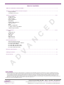
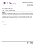
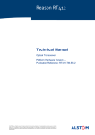
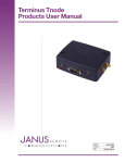
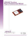
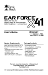
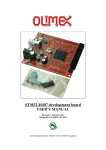
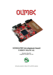
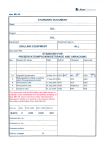
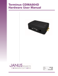
Terminus T2
Products User Manual –
Hardware Guide
Bulletin
Revision
Date
JA15-UM
A03
17 Sept 2014
TABLE OF CONTENTS
TABLE OF CONTENTS and DISCLAIMER............................................................................................................................... 2
Terminus T2 Cellular Platform General Description................................................................................................................. 3
Plug-In Terminals
Cortex M3™ Processor
E
D
Terminus T2 Peripherals...................................................................................................................................................... 4-12
Accelerometer
SD Memory Card
USB OTG (FS)
RS-232 Serial Port
DB9 (MALE)
RS-485 J1708 Serial Port
CAN Transceiver
GPIO
Optical Isolated Input
4 - 20ma Current Loop Outputs
Cellular Plug-In Terminal
N
C
External Interfaces............................................................................................................................................................ 13-14
LEDs
Cellular RF Port
GPS RF Port
SIM Card
SD Card
DB9 Connector
USB Connector
A
Electrical Specifications......................................................................................................................................................... 15
Absolute Maximum Ratings
Recommended Operating Conditions
I/O Levels (2.8V CMOS)
I/O Levels (RS-232 Transceiver)
I/O Levels (RS-485 Transceiver)
I/O Levels (CAN Transceiver)
V
Mechanical Specifications..................................................................................................................................................... 16
Ordering Information.............................................................................................................................................................. 17
A
D
Revision History..................................................................................................................................................................... 17
DISCLAIMER
The information contained in this document is the proprietary information of Connor-Winfield Corporation and its affiliates (Janus Remote Communication). The contents are confidential and any disclosure to
persons other than the officers, employees, agents or subcontractors of the owner or licensee of this document, without the prior written consent of Connor-Winfield, is strictly prohibited. Connor-Winfield
makes every effort to ensure the quality of the information it makes available. Notwithstanding the foregoing, Connor-Winfield does not make any warranty as to the information contained herein, and does
not accept any liability for any injury, loss or damage of any kind incurred by use of or reliance upon the information. Connor-Winfield disclaims any and all responsibility for the application of the devices
characterized in this document, and notes that the application of the device must comply with the safety standards of the applicable country, and where applicable, with the relevant wiring rules. ConnorWinfield reserves the right to make modifications, additions and deletions to this document due to typographical errors, inaccurate information, or improvements to programs and/or equipment at any time and
without notice. Such changes will, nevertheless be incorporated into new editions of this application note.
All rights reserved 2011 Connor-Winfield Corporation
Terminus T2 User Guide JA15-UM
Page 2
Rev: A03
Date: 09/17/14
© Copyright 2014 Janus Remote Communications Specifications subject to change without notice
All Rights Reserved See website for latest revision.
Not intended for life support applications.
Terminus T2 Cellular Platform:
A
N
C
E
D
The Terminus T2 provides a complete wireless communication device with integrated ARM Cortex M3™ processor,
expanded peripheral set and cellular communication protocols to fit any application. The ARM Cortex M3™
processor has a large support community available to reference while developing applications. Additionally, Janus
has hardware/software partners waiting to assist users in quickly getting your product to market.
Plug-In Terminals:
D
V
Cellular communication protocols for the Terminus T2 are powered by Terminus Plug-In terminals. Plug-In Terminus
offer easy integration and interchangeability of communication protocols between GSM/GPRS, CDMA, HSPA and
more by combining full M2M functionality with the flexibility of a standard “plug-in” DIP design. These terminals
share the same mechanical footprint and offer users the ability to configure their applications for communications
via any cellular protocol. By using these modules to power the cellular technology of the Terminus T2, users can
easily change cellular technology without having to change platforms. The Terminus T2 provides one platform that
supports current cellular technology with the future in mind.
A
Terminus T2 Cortex M3™ Processor:
The Terminus T2 has an internal ARM 32-bit Cortex M3™ 150MIPS processor with 256KB Flash/96KB+4KB RAM.
For a complete description of the processor refer to the ST Microelectronics data sheet.
ST Microelectronics Part Number: STM32F205ZCT6
Terminus T2 User Guide JA15-UM
Page 3
Rev: A03
Date: 09/17/14
© Copyright 2014 Janus Remote Communications Specifications subject to change without notice
All Rights Reserved See website for latest revision.
Not intended for life support applications.
Terminus T2 Peripherals:
The following section describes the connections of external peripherals.
Accelerometer:
A digital 3-axis accelerometer is connected to the I2C2 interface of the Cortex M3™ processor. The
accelerometer has programmable acceleration range, low pass filter and motion triggered interrupts. For a
complete description of the accelerometer refer to the Bosch data sheet.
Bosch data sheet: BMA222
STM32F205ZCT6
Pin Name
Pin Description
2
12
1
5
6
PF0
PF1
PE1
PE4
PE5
I2C2_SDA
I2C2_SCL
GPIO
GPIO
GPIO
E
C
SDA
SCL
SA0
INT1
INT2
D
Accelerometer Interconnects:
BMA222
Pin
Name
N
SD Memory Card:
A microSD memory card socket is connected to the SDIO Interface of the Cortex M3™ processor. The SDIO
interface is complaint with the SD Memory Card Specification V2.0.
SD Memory Card Interconnects:
SD Card
STM32F205ZCT6
Pin Name
Pin Name
Pin Description
SDIO_CLK
SDIO_CMD
SDIO_D0
SDIO_D1
SDIO_D2
SDIO_D3
D
V
A
CLK
PC12
CMD
PD2
D0
PC8
D1
PC9
D2
PC10
D3
PC11
CDPC0
GPIO
A
USB OTG (FS):
A USB OTG connector is connected to the full-speed device/host/OTG port of the Cortec-M3 processor. The
USB OTG FS peripheral is compliant with the USB 2.0 specification and with the OTG 1.0 specification. It has
software-configurable endpoint setting and supports suspend/resume. The Terminus T2 does not supply VBUS.
USB OTG Interconnects:
USB OTG
Pin
Name
STM32F205ZCT6
Pin Name
Pin Description
1
2
3
4
PA9
PA11
PA12
PA10
VBUS
D-
D+
ID
OTG_FS_VBUS
OTG_FS_DM
OTG_FS_DP
OTG_FS_ID
Terminus T2 User Guide JA15-UM
Page 4
Rev: A03
Date: 09/17/14
© Copyright 2014 Janus Remote Communications Specifications subject to change without notice
All Rights Reserved See website for latest revision.
Not intended for life support applications.
Terminus T2 Peripherals continued:
RS-232 Serial Port:
An RS-232 level serial port is connected to USART3 of the Cortex M3™ processor. This serial port supports RTS/
CTS handshaking. An addition RS-232 level serial port is exposed via the 30-pin locking header and is directly
connected to the diagnostic port of the Plug-in Terminus. For a complete description of the RS-232 line driver
refer to the Intersil data sheet.
Intersil data sheet: ISL83387
DB9 RS-232 Interconnects:
DB9 (MALE)
Pin
Name
STM32F205ZCT6
Pin Name
Pin Description
2
3
7
8
5
PB11
PB10
PD12
PD11
N/A
D
USART3_RX
USART3_TX
USART3_RTS
USART3_CTS
N/A
E
RXD (Input)
TXD (Output)
RTS (Output)
CTS (Input)
GROUND
30-pin Locking Header RS-232 Interconnects:
30-pin Locking Header
Plug-in Terminus
Pin
Name
Pin Name
Pin Description
Line Driver Interconnects:
ISL83387
Pin
Name
9
11
24
14
13
TRACE_RX
TRACE_TX
C
TRACE_RX (Input)
TRACE_TX (Output)
STM32F205ZCT6
Pin Name
Pin Description
INVALID (Output)
FORCEON (Input)
FORCEOFF (Input)
N
7
8
PE15
PF3
PF4
GPIO
GPIO
GPIO
A
Note: Refer to Intersil data sheet for a complete description of these control I/O.
RS-485 J1708 Serial Port:
D
V
An RS-485 level serial port is connected to USART2 of the Cortex M3™ processor. This serial port is configured
for J1708 operation. No external termination or filtering is required for J1708 operation. For a complete
description of the RS-485 line driver refer to the Intersil data sheet.
Intersil data sheet:ISL8487
Pin Description
5
6
Non-inverting receiver I/O
Inverting receiver I/O
A
30-pin Locking Header RS-485 Interconnects:
30-pin Locking Header
ISL8487
Pin
Name
Pin
RS-485A
RS-485B
6
7
Line Driver Interconnects:
ISL8487
Pin
Name
STM32F205ZCT6
Pin Name
Pin Description
1
N/A
PD6
PD5
Note:
RO (Output)
DIN (Input)
USART2_RX
USART2_TX
DIN input is inverted and connected to DE pin of the Intersil line driver. DI and RE inputs of the Intersil line driver are pulled-low.
Terminus T2 User Guide JA15-UM
Page 5
Rev: A03
Date: 09/17/14
© Copyright 2014 Janus Remote Communications Specifications subject to change without notice
All Rights Reserved See website for latest revision.
Not intended for life support applications.
Terminus T2 Peripherals continued:
CAN Transceiver:
A CAN transceiver is connected to the CAN1 controller of the Cortex M3™ processor.
The CAN controller is compliant with the 2.0A and B (active) specifications with a bitrate up to 1 Mbit/s. The CAN
interface can receive and transmit standard frames with 11-bit identifiers as well as extended frames with 29-bit
identifiers. The CAN interface has three transmit mailboxes, two receive FIFOS with 3 stages and 28 scalable filter
banks. The 256 bytes of SRAM that is allocated for the CAN interface is not shared with any other Cortex M3™
peripheral. For a complete description of the CAN transceiver refer to the NXP data sheet.
NXP data sheet:
TJF1051
TJF1051
Pin
Pin Description
9
10
6
7
LOW-level CAN bus line
HIGH-level CAN bus line
E
CAN_LO
CAN_HI
D
30-pin Locking Header CAN Interconnects:
30-pin Locking Header
Pin
Name
STM32F205ZCT6
Pin Name
Pin Description
1
4
8
PD1
PD0
PE6
Operating Modes
Mode
Inputs
Pin S
CAN_TX
LOW
LOW
HIGH
LOW
HIGH
X [2]
Outputs
CAN Driver
CAN_RX
A
Normal
Silent
CAN1_TX
CAN1_RX
GPIO
N
CAN_TX (Input)
CAN_RX (Output)
S (Input)
C
CAN Transceiver Interconnects:
TJF1051
Pin
Name
Active [1]
Active [1]
Active [1]
Dominant
Recessive
Recessive
LOW if the CAN bus is dominant, HIGH if the CAN bus is recessive
[2]
X = don’t care.
A
D
V
[1]
Terminus T2 User Guide JA15-UM
Page 6
Rev: A03
Date: 09/17/14
© Copyright 2014 Janus Remote Communications Specifications subject to change without notice
All Rights Reserved See website for latest revision.
Not intended for life support applications.
Terminus T2 Peripherals continued:
GPIO:
The Terminus T2 exposes 14 CMOS level general propose I/O’s. The GPIO can be used as GPIO or alternate
functions including SPI, I2C, USART, ADC and DAC. The GPIO’s are available via the 30-pin locking header.
30-pin Locking Header
Pin
Description
STM32F205ZCT6
Pin Name
Alternate Function
14
16
18
20
22
24
26
28
30
29
25
23
21
19
PA15
PB3
PB4
PB5
PB8
PB9
PA0
PA1
PA2
PA3
PA4
PA5
PA6
PA7
E
D
SPI1_NSS
SPI1_SCK
SPI1_MISO
SPI1_MOSI
I2C1_SCL
I2C1_SDA
UART4_TX , ADC123_CH0, WKUP
UART4_RX , ADC123_IN1
ADC123_IN2
ADC123_IN3
ADC12_IN4 , DAC1_OUT
ADC12_IN5 , DAC2_OUT
ADC12_IN6
ADC12_IN7
C
GPIO1
GPIO2
GPIO3
GPIO4
GPIO5
GPIO6
GPIO7
GPIO8
GPIO9
GPIO10
GPIO11
GPIO12
GPIO13
GPIO14
N
Optical Isolated Input:
An optical isolated input is available on the Terminus T2. The output of the isocoupler is connected to the
Cortec-M3 via GPIO PC13. PC13 can be configured as an RTC Alternate Function that can wake the STM32 from
power savings modes.
7 – 28 Vdc
3,750 Vrms
A
Voltage Input Range:
Input-output isolation Voltage: D
V
4 – 20ma Current Loop Outputs:
Two 4-20ma current loop outputs are connected to ADC inputs of the Cortec-M3 processor. Sensor power supply
is directly connected to the supply input of the Terminus T2. The sensor supply outputs are available via the 30pin external locking header. The current loop circuits protect against over current events. If there is an over current
event the sensor supply output is latched off and the CL_ITRIPn output transitions low. To reset the sensor supply
the CL_RESETn input must be held low between 2us to 15us. To put the current loop sensors in shutdown mode
hold the CL_RESETn input low at least 150us.
STM32F205ZCT6
Pin Name
Pin Description
VIN
CL_ITRIP1
CL_RESET1
CLV1
NC
PD13
PD14
PB0
A
4-20ma Current Loop-1 Interconnects:
Current Loop 1
Pin Name
Description
Sensor Supply Input
Over Current Output
Reset Input
Sensor Current Output
N/A
GPIO
GPIO
ADC12_IN8
4-20ma Current Loop-2 Interconnects:
Current Loop 2
Pin Name
Description
STM32F205ZCT6
Pin Name
Pin Description
VIN
CL_ITRIP2
CL_RESET2
CLV2
NC
PD15
PE0
PB1
Sensor Supply Input
Over Current Output
Reset Input
Sensor Current Output
Terminus T2 Peripherals continued:
N/A
GPIO
GPIO
ADC12_IN9
Terminus T2 User Guide JA15-UM
Page 7
Rev: A03
Date: 09/17/14
© Copyright 2014 Janus Remote Communications Specifications subject to change without notice
All Rights Reserved See website for latest revision.
Not intended for life support applications.
Cellular Plug-In Terminal:
A socket for a Janus Remote Communication Plug-In terminal is available on the Terminus T2. There are GSM/
GPRS, CDMA/1xRTT, and HSPA versions of the Plug-In terminal available. All required I/O to control the Plug-In
terminal including USB; USART and GPIO’s are described below. For a complete technical description of the
Plug-In Terminus, please refer to the Janus Remote Communications User Guide.
Janus Remote Communications Part Numbers: GSM865CF, CDMA864CF and HSPA910CF
Plug-In MODEM Interconnects:
STM32F205ZCT6
Pin Name
Function
Plug-In MODEM
Pin
Name
Function
PC1
PC2
PC3
PG0
PC4
PG1
PD10
PB7
PB6
NC
NC
PC6
PC7
PG12
PG15
PD3
PD9
PD8
PD7
PB15
PB14
PB12
PG6
PG5
PG8
PG7
PG2
PG3
PG4
3
19
20
18
17
16
35
34
33
13
14
9
4
11
6
5
10
8
7
28
27
30
43
42
41
40
38
37
36
Plug-In Enable Input
ON OFF Toggle Input
Cellular Reset Input
Power Monitor Output
Service Input
Status LED
MS20 GPS Reset Input
MS20 NMEA TXD Output
MS20 NMEA RXD Input
Trace Port – TXD Output
Trace Port – RXD Input
DCE Serial Port – TXD Input
DCE Serial Port – RXD Output
DCE Serial Port – RTS Input
DCE Serial Port – CTS Output
DCE Serial Port – DSR Output
DCE Serial Port – DTR Input
DCE Serial Port – DCD Output
DCE Serial Port – RING Output
USB D+
USB DUTG USB_ID Analog Input
General Purpose IO #1
General Purpose IO #2
General Purpose IO #3
General Purpose IO #4
General Purpose IO #5
General Purpose IO #6
General Purpose IO #7
D
V
E
D
ENABLE SUPPLY
ON_OFF
RESET
PWRMON
SERVICE
CELLULAR_LED
GPS_RESET
GPS_TX
GPS_RX
TRACE_TX
TRACE_RX
TXD
RXD
RTS
CTS
DSR
DTR
DCD
RING
USB_D+
USB_D-
USB_ID
GPIO1
GPIO2
GPIO3
GPIO4
GPIO5
GPIO6
GPIO7
C
N
A
GPIO – OD
GPIO – OD
GPIO – OD
GPIO
GPIO
GPIO
GPIO – OD
USART1_RX
USART1_TX
NC
NC
USART6_TX
USART6_RX
USART6_RTS
USART6_CTS
GPIO
GPIO
GPIO
GPIO
OTG_HS_DP
OTG_HS_DM
OTG_HS_USBID
GPIO
GPIO
GPIO
GPIO
GPIO
GPIO
GPIO
A
Terminus T2 Peripherals - Continued:
Terminus T2 User Guide JA15-UM
Page 8
Rev: A03
Date: 09/17/14
© Copyright 2014 Janus Remote Communications Specifications subject to change without notice
All Rights Reserved See website for latest revision.
Not intended for life support applications.
Cellular Plug-In Terminal - Continued:
ENABLE SUPPLY Truth Table:
ENABLE SUPPLY (PC1, GPIO – OD)
Function
0
High-Z
Plug-In terminal power supply is disabled.
Plug-In terminal power supply is enabled.
ON_OFF Truth Table:
ON_OFF (PC2, GPIO – OD)
Function
0
High-Z
D
Hold time to turn Plug-In terminal on: > 1s
Hold time to turn Plug-In terminal off: > 2s
Run state. Input should remain in this state after the Plug-In terminal has been turned on or off.
HSPA910CF Hold time to turn Plug-In terminal on: > 5s
HSPA910CF Hold time to turn Plug-In terminal off: > 3
E
Note:
Toggle state. Input should remain in this state for a specified amount of time in order to turn On or Off the Plug-In terminal.
Function
0
High-Z
Reset State.
Hold time to reset Plug-In terminal: > 200ms
Run state. Input should remain in this state when Plug-In terminal is operational.
C
RESET Truth Table:
RESET (PC3, GPIO – OD)
N
PWRMON Truth Table:
PWRMON (PC13)
Function
0
1
When turning off the Plug-in Terminus or when in an off state all driving I/O must be set to high-z and pull-ups disabled. If inputs are driven high while the Plug-in Terminus is in an off state, the POWERMON pin might read logic 1 giving a false on state status.
0
High-Z
SERVICE state is enabled.
SERVICE state is disabled.
Applies to GSM Terminus T2 models only. The service pin is used to upgrade the cellular module firmware from TRACE RX, TRACE TX that
is exposed via the 30-pin locking header.
D
Note: Function
V
SERVICE Truth Table:
SERVICE (PC4, GPIO – OD)
A
Note:
Plug-In terminal is in an off state.
Plug-In terminal is in an on state.
Function
0
1
Run state. Input should remain in this state when MS20 GPS receiver is
operational.
MS20 GPS Receiver Reset State.
Hold time to reset MS20 GPS receiver: > 1ms
A
GPS_RESET Truth Table:
GPS_RESET (PD10, GPIO - OD)
Note: Applies to GSM Terminus T2 with MS20 GPS receiver only.
ENABLE VBUS Truth Table:
ENABLE VBUS (PC5 GPIO - OD)
Function
0
High-Z
Plug-In terminal VBUS input is set to ground.
Plug-In terminal USB_VBUS input is set to 5Vdc.
Note: Applies to CDMA and HSPA Terminus T2 models only.
Terminus T2 User Guide JA15-UM
Page 9
Rev: A03
Date: 09/17/14
© Copyright 2014 Janus Remote Communications Specifications subject to change without notice
All Rights Reserved See website for latest revision.
Not intended for life support applications.
Terminus T2 Peripherals - Continued:
A
D
V
A
N
C
E
D
Cellular Plug-In Terminal - Continued:
Cellular Plug-In Terminal: Turn on Sequence
Terminus T2 User Guide JA15-UM
Page 10
Rev: A03
Date: 09/17/14
© Copyright 2014 Janus Remote Communications Specifications subject to change without notice
All Rights Reserved See website for latest revision.
Not intended for life support applications.
Terminus T2 Peripherals - Continued:
A
N
C
E
D
Cellular Plug-In Terminal - Continued:
A
D
V
* HSPA models = 3 s
Cellular Plug-In Terminal: Turn off Sequence
Terminus T2 User Guide JA15-UM
Page 11
Rev: A03
Date: 09/17/14
© Copyright 2014 Janus Remote Communications Specifications subject to change without notice
All Rights Reserved See website for latest revision.
Not intended for life support applications.
Terminus T2 Peripherals - Continued:
Cellular Plug-In Terminal: Reset Sequence
A
D
V
A
N
C
E
D
Cellular Plug-In Terminal - Continued:
Terminus T2 User Guide JA15-UM
Page 12
Rev: A03
Date: 09/17/14
© Copyright 2014 Janus Remote Communications Specifications subject to change without notice
All Rights Reserved See website for latest revision.
Not intended for life support applications.
External Interfaces:
Reset Button:
The Reset button is connected to the reset input of the Cortex M3™ processor.
LED
Color
STM32F205ZCT6
Pin Name
Function
RED
YELLOW
GREEN
PE12
PE13
PE14
GPIO
GPIO
GPIO
Description
Center Pin
Outer Conductor
Cellular Signal
SIGNAL Ground
C
SMA - FEMALE
Pin
E
Cellular RF Port:
D
LEDs:
The Terminus T2 has three LEDs available. Each LED is controllable via a GPIO of the Cortex M3™ processor.
For Cellular RF Port details, view the Plug-In Terminus Manual as reference.
N
GPS RF Port:
Description
Center Pin
Outer Conductor
GPS Signal, 3.7 Vdc nominal supplied from Terminus to power active antenna.
Signal ground
A
MCX - FEMALE
Pin
V
For GPS RF Port details, view Plug-In Terminus User Manual as reference
D
SIM Card:
Standard locking SIM card connector available on bottom of enclosure.
A
Power Supply:
The Terminus T2 power supply jack accepts input voltages from 7 to 28 VDC and requires a nominal current
sourcing capacity of 5W (maximum 10W). This jack accepts a barrel type plug with a receptacle for a 2.1mm
center conductor. Power supply connection is also available via the 30-pin locking header.
Pin
Center Pin
Outer Conductor
Description
Supply (+)
Supply (-)
SD Card:
Standard microSD card (15 mm × 11 mm × 1.0 mm)
Terminus T2 User Guide JA15-UM
Page 13
Rev: A03
Date: 09/17/14
© Copyright 2014 Janus Remote Communications Specifications subject to change without notice
All Rights Reserved See website for latest revision.
Not intended for life support applications.
External Interfaces continued:
DB9 Connector:
Standard DB9 male connector
PIN
Description
2
3
5
7
8
RXD
TXD
Ground
RTS
CTS
Input
Output
Supply
Output
Input
Supply Input
Bi-Dir
Bi-Dir
Input
Ground
Ground
30-Pin Locking Header:
Description
1
2
3
5
6
7
8
9
10
13
14
15
16
18
19
20
21
22
23
24
25
26
28
29
30
4,11,12,17,27
Supply Enable
Power Supply Input
Optical Isolated Input
RS485_A
RS485_B
TRACE Port Receive
TRACE Port Transmit
CAN_LO
CAN_HI
Current Loop Supply Channel 1
GPIO1
Current Loop Supply Channel 2
GPIO2
GPIO3
GPIO14
GPIO4
GPIO13
GPIO5
GPIO12
GPIO6
GPIO11
GPIO7
GPIO8
GPIO10
GPIO9
Supply Ground
A
V
D
A
Direction
Level
Input
N/A
Input
Bi-Directional
Bi-Directional
Input
Output
Bi-Directional
Bi-Directional
Output
Bi-Directional
Output
Bi-Directional
Bi-Directional
Bi-Directional
Bi-Directional
Bi-Directional
Bi-Directional
Bi-Directional
Bi-Directional
Bi-Directional
Bi-Directional
Bi-Directional
Bi-Directional
Bi-Directional
N/A
Supply
Supply
Supply
RS-485
RS-485
RS-232
RS-232
CAN
CAN
Supply
2.8V CMOS
Supply
2.8V CMOS
2.8V CMOS
2.8V CMOS
2.8V CMOS
2.8V CMOS
2.8V CMOS
2.8V CMOS
2.8V CMOS
2.8V CMOS
2.8V CMOS
2.8V CMOS
2.8V CMOS
2.8V CMOS
Ground
N
PIN
E
Description
1
VBUS
2
D+
3
D-
4
USB_ID
5
Shield
C
PIN
D
USB Connector:
Standard mini AB USB connector
Samtec Part Number:
Housing:
IPD1-15-D-K
Janus Store Part Number:
Housing:
XT-507-G
Contacts:
CC79L-2024-01-L
Contacts:
XT-479-G
Terminus T2 User Guide JA15-UM
Page 14
Rev: A03
Date: 09/17/14
© Copyright 2014 Janus Remote Communications Specifications subject to change without notice
All Rights Reserved See website for latest revision.
Not intended for life support applications.
Electrical Specifications:
Absolute Maximum Ratings:
Parameter
Minimum
Storage Temperature
Supply (Supply & Enable Input)
VIN (Digital Inputs 2.8V CMOS)
VIN (RS-232 Inputs)
VIN (RS-485 Inputs)
VIN (CAN Inputs)
Nominal
Maximum
Unit
Note
-
-
-
-
-
-
85
60
3.6
25
12.5
58
°C
Volt
Volt
Volt
Volt
Volt
1
1,2
1
1
1
1
-40
-40
-0.3
-25
-8
-58
Nominal
Maximum
-
-
-
-
-
-
50
50
50
28
-
TBD
-30
-30
-30
7
1.5
-
Unit
Note
E
Operational Temperature:
GSM865T2
CDMA864T2
HSPA910T2
Supply (Supply & Enable Input)
Peak Supply Current
Average Supply Current
°C
Volt
Amp
Amp
C
Recommended Operating Conditions:
Parameter
Minimum
D
Notes:
1)
Operation of the device at these or any other conditions beyond those listed under Recommended Operating Conditions is not implied.
Exposure to Absolute Maximum Rating conditions for extended periods of time may affect device reliability.
2)
The supply inputs are protected from reverse voltage and transients beyond the Recommended Operating Conditions. If transients persist the
supply will be latched in a disable state. Once disabled the supply will need to be cycled off and on to reset.
1
2
N
Notes:
1)
Peak Supply Current specification is stated as the minimum amount of current the external power supply must supply during the TX burst of
the embedded cellular radio. Please refer to the Plug-In User Manual for power supply characteristics of the embedded Plug-In Module embedded
in the Terminus T2. Plug-In User Manual can be downloaded at http://www.janus-rc.com/terminuscf.html
2)
Average Supply Current specification is stated as the maximum average current the Terminus T2terminal can draw while maintaining junction
temperatures within the internal power supply IC’s specifications. It is the applications responsibility to maintain operation within this limit to maintain
reliable operation over the life of this terminal product.
Minimum
Nominal
Maximum
Unit
Note
Input Voltage Low - Vil
Input Voltage High - Vih
Output Voltage Low – Vol
Output Voltage High – Voh
Output Current - Io
Pull-up Resistance - RPULLUP
-0.3
1.96
-
2.4
-
30
-
-
-
-
-
40
0.84
3.1
0.4
-
8
50
Volt
Volt
Volt
Volt
mA
kOhm
1
1
V
A
I/O Levels (2.8V CMOS)
Parameter
D
Notes:
1) Test conditions: Max Io.
A
I/O Levels (RS-232 Transceiver)
Please refer to Intersil’s data sheet for a complete listing of specifications for the RS-232 transceiver used in the
Terminus T2.
Intersil Part Number:
ISL83387
I/O Levels (RS-485 Transceiver)
Please refer to Intersil’s data sheet for a complete listing of specifications for the RS-485 transceiver used in the
Terminus T2.
Intersil Part Number:
ISL8487
I/O Levels (CAN Transceiver)
Please refer to NXP’s data sheet for a complete listing of specifications for the CAN transceiver used in the
Terminus T2.
NXP Part Number:
TJF1051T
Terminus T2 User Guide JA15-UM
Page 15
Rev: A03
Date: 09/17/14
© Copyright 2014 Janus Remote Communications Specifications subject to change without notice
All Rights Reserved See website for latest revision.
Not intended for life support applications.
A
D
V
A
N
C
E
D
Mechanical Specifications:
Terminus T2 User Guide JA15-UM
Page 16
Rev: A03
Date: 09/17/14
© Copyright 2014 Janus Remote Communications Specifications subject to change without notice
All Rights Reserved See website for latest revision.
Not intended for life support applications.
Terminus T2
Products User Manual –
Hardware Guide
Ordering Information
Ordering Information
Description
GSM865T2 v1 GSM865T2 v2
CDMA864T2 v2
CDMA864T2 v3
CDMA864T2 v4
HSPA910T2 v1
EVDO910T2 v3
WiFi1500T2 v1
WiFi1500T2 v2
GSM/GPRS GPS Enabled
GSM/GPRS without GPS
CDMA-1xRTT (Sprint)
CDMA-1xRTT (Verizon)
CDMA-1xRTT (Aeris)
HSPA+/UMTS/EDGE/GPRS/GSM
EV-DO (Verizon) (coming soon)
Wi-Fi GPS Enabled (coming soon)
Wi-Fi without GPS (coming soon)
Revision History
Revision Revision Date
Note
A00
A01
A02
A03
Advanced Release - User Manual
Edits to Peripherals Section
Updates to Ordering Information
Update to Operating Temperature
03/13/12
08/10/12
09/06/12
09/14/14
Division of The Connor-Winfield Corporation
2111 Comprehensive Drive • Aurora, Illinois 60505
630.499.2121 • Fax: 630.851.5040
www.janus-rc.com
Janus Remote Communications Europe
Bay 143
Shannon Industrial Estate
Shannon, Co. Clare, Ireland
Phone: +353 61 475 666