1
VoiceRecognition
Controlled
Sailboat
FEATURE
ARTICLE
Mike Smith, Todd Turner,
& Steve Alvey
Speech-Recognition Control
Aids Disabled Sailors
For his engineering
design project at the
University of Calgary,
Todd and his team
created a prototype for
a voice-recognition
system that enables
quadriplegic sailors to
independently control
a Martin 16 sailboat.
Batten down the
hatches for a storm of
information about this
practical and
resourceful project.
www.circuitcellar.com/online
t
he Canadian
Engineering Accreditation Board
(CEAB) now requires all
graduating engineering students to
have significant team design experience to prepare them for “real life” in
industry. At the University of
Calgary, to meet CEAB requirements,
students have the opportunity of developing a semiacademic project, but
many are taking an alternative approach that is more work, more fun,
and far more real.
Students are finding their own
projects from local industry or the
community, which gives them a full
year working with real projects and
customers. Four students must act as
project managers and engineers, work
as a team, and follow a proper lifecycle approach to planning, designing,
implementing, and testing. A public
presentation of the work brings things
together and serves as the final acceptance test.
After completing a 16-month internship at MCK Communications,
Todd Turner returned for his final
year and his design project. His team
decided to create a prototype for a
voice-recognition system for a Martin
16 sailboat. Steve Alvey, Todd’s customer, and the Disabled Sailing Association of Alberta had modified the
Martin 16, shown in Photo 1, so quadriplegic sailors could sail independently. The boat, funded by a grant
from the Royal Bank of Canada, includes a 300-kg keel to prevent capsizing and a custom-designed seat to
support the disabled sailor.
Quadriplegic sailors have already
used this boat at regattas in Calgary
and throughout Canada. The
Autohelm, pictured in Photo 2, provides the necessary electronics to
control the sails and helm using a
joystick or a sip-and-puff mechanism.
The controller also accepts commands
Photo 1—The Martin 16 sailboat,
Royal Liberty, funded by the Royal
Bank of Canada, has a 300-kg
keel and is designed for quadriplegic sailors. The sailor controls the
sails and helm using a sip-and-puff
mechanism. An able-bodied
companion comes along for the
ride. His hand can be seen near
the back of the boat.
CIRCUIT CELLAR ® ONLINE
December
1999
1
and a variety of basic
debugging tools.
CONTROLLING THE
MARTIN 16
address flag, so a device recognizes
when the address refers to it. The
remaining values define the command
to be acted on.
This approach is referred to as a
multidrop mode because the master
controller can direct commands to
multiple devices connected to the
same serial link. Each slave device is
programmed to recognize its own
address and a global-broadcast address, enabling the master to efficiently command slaves
simultaneously or individually. The
transmitting device first sends a 9-bit
value containing the receiver’s address. When this address is recognized, the receiver acts on the data
that follows.
With this device,
sailors can remotely
control the Martin 16,
adjusting both the sail
and helm, through the
speech-recognition
system. Because a high
degree of control is
Photo 2—A joystick or a sip-and-puff controller allows a disabled person to
needed, the voicemanage the Martin 16 Autohelm/Windlass System.
control system supports both discrete
word commands and continuous
over a serial link from the
sound commands.
companion’s remote control. A variFor example, the command “RUDety of devices remotely send comDER” places the system into ruddermands or information to the
controller or each other over this link. control mode. The continuous sound
“EEEEE” causes the Autohelm to
Todd’s team needed to add a voiceCREATING A SOFTWARE UART
change course by +1°. The course
control component to the serial link
For this project, we need a univerchange continues to increase as long
without disturbing its other funcsal asynchronous receiver transmitter
as the sailor holds the sound. Alternations.
(UART) to transmit data asynchroThe design project was divided into tively, if the sailor holds the sound
nously. To avoid adding external de“AAAAH,” the Autohelm alters the
three technical sections:
vices to the design, many
course in –1° increments.
microcontrollers have on-chip
The system also greatly increases
• conditioning voice input
UARTs. In fact, the SHARC processor
the confidence of the disabled sailors
• developing a speech-recognition
has two on-chip time-divisionby adding the equivalent of a push-toengine
mulitplexing serial ports (known as
talk command for the safety.
• interfacing between the speechSPORTs), which it uses to transfer
recognition engine and the Mardata at up to 40 Mbps in numerically
tin 16 controller using a 9-bit
intensive real-time applications.
PLUG AND SAY
UART
However, these ports are synchroThe SeaTalk bus from Raytheon
nous, not asynchronous.
forms the serial connection between
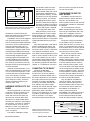
As you can see in Figure 1, the EZThis article focuses on the interthe speech-recognition system and the
Kit Lite evaluation board has a stanface. The other sections will be covassociated controller. Because the
dard 16550 PC UART. However, this
ered in subsequent papers.
controller already supports the
UART is not easily accessible as it is
SeaTalk commands sent by the
companion’s safety
THE HARDWARE
remote, we could
They chose the Analog Devices
Pushbutton switches
Flag LEDs
Power
easily add the voiceSHARC EZ-Kit Lite evaluation board
Flag
LED
control system to the
for a number of reasons. This board’s
IRQ
Power
existing system just
main processor, the ADSP-21061
RESET
connector
by plugging the
SHARC DSP, operates at 40 MIPS,
JTAG
Emulator
port
Line in stereo
connector
voice-control box
peaking at 120 MFLOPS. As you can
SHARC
CODEC
Mic in stereo
Link
Line
out stereo
into the SeaTalk
see in Figure 1, the board includes an
External link ports(2)
connectors
port.
AD1847 stereo CODEC, which takes
(unpopulated)
External
External
serial port
processor
The serial comvoice input via a microphone. A synconnector
bus
Expansion
(unpopulated)
mands for the
chronous serial line to the SHARC
connectors
(unpopulated)
SeaTalk bus are sent
processor connects to the CODEC,
UART
PROM
in an asynchronous
which is a sigma-delta oversampling
format at 4800 bps
converter that digitally filters the
Asynchronous
with 8 data bits, 1
signal to avoid aliasing problems.
serial port
RS-232
connector
drivers
The development software includes address/data flag, 1
start, and 1 stop bit.
both an optimizing C compiler and an
Figure 1—The SHARC EZ-Kit Lite evaluation board uses an ADSP-21061
The first value in a
assembler. Program development can
SHARC DSP as its main processor. The chip operates at 40 MIPS and peaks at
command sets the
be handled using the onboard kernel
120 MFLOPS.
2
December
1999
CIRCUIT CELLAR ® ONLINE
www.circuitcellar.com/online
service routine to process the characthat SHARC stands for Super
ter from the DUART.
Harvard
ARChitecture)
has
1
47
40 39
24 23
32 31
16 15
8 7
0
MB of internal RAM that can be
EPROM
configured as independent proCONFIGURING THE DSP FOR
boot
gram and data memory. To read
UART ACCESS
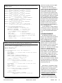
16-bit packed
and write to an off-chip external
The SHARC processor has four
Float or fixed, D31-D0, 32-bit packed
memory location, you activate
external memory selects and three
Extended float
the appropriate memory select
IRQ pins. On the EZ-Kit Lite,
Instruction fetch
(MS) line. When the MS signal is memory-select line MS3 and interrupt
activated, an address is placed on line IRQ0 are available to manipulate
Figure 2—The 48-bit SHARC external port handles a variety of
the memory bus and a read (RD)
the DUART.
data and instruction formats. Transmission of 8-bit data requires
or write (WR) signal is asserted.
On microcontrollers, like the
special positioning of the device on the SHARC data bus.
This approach differs from
68332, manipulating the chip-select
other processors, which multilines can get complicated. Each chipplex READ/WRITE* control signals.
select line is mapped to a block of
intended for communications beaddresses anywhere in memory space
tween the board kernel and diagnostic Some processors even require additional decoding logic, as there are no
and configured for 8- or 16-bit operatools running on the host PC.
The SHARC user’s manual suggests a external memory-select or chip-enable tions.
signals generated directly by the proThings are a little more wasteful
way around the problem by using the
on the 21061. Here you choose bepins on the evaluation board’s expansion cessor.
After the MS and RD or WR signal
tween 48-bit access or no access. As a
connector to clock out and receive bits
asserts, the DSP places data on the
result, you manipulate bits to ensure
from the multidrop serial line. The
bus in a write operation (the periphthat the 8-bit value is correctly placed
software UART uses the SHARC general does it with a read). To match the for transmission and to clear unneceseral-purpose I/O flag pins as well as the
slow speed of the external device,
sary bits from received values.
onboard programmable timer interrupt.
wait states can be programmed for the
There are four external memory
The UART is emulated by detecting the
DSP to access a specific memory loca- banks, which correspond to the
start bit through programming and
tion. On the 21061, you can control
memory-select signals, on the
oversampling the received signal. The
the number of wait states through an
SHARC starting with memory bank 0
nine bits needed for communications
external acknowledge signal (ACK),
at address 0x00400000. Memory bank
are clocked by reading one of the flag
an internally programmed wait-state
1 follows memory bank 0, memory
pins. Similarly, transmission occurs by
register, or a combination of the two.
bank 2 follows memory bank 1, and
setting and clearing a second flag pin to
so on. Each bank is the same size and
clock out characters.
can be configured from 8-KB of 32-bit
Although a software UART is feaCONNECTING TO THE DUART
words to 256-MB of words. Although
sible, the implementation would take
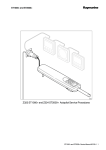
The Exar XR-88C681A
the base address of memory bank 0 is
a lot of time. More important, it was
UART(actually a dual UART or
the same, the base address of the folnot clear that there would be enough
DUART since it has two separate
lowing memory banks varies based on
room in the SHARC’s internal
transceiver channels) handles the 9the size of the preceding banks.
memory for this and the speech-recog- bit serial transmission to the SeaTalk
Only 16 registers are needed to
nition software. Clearly, we had to
bus. Figure 4 shows the connections
control the UART. We innocently
develop a standard interface to an
necessary to interface the 88C681
decided to code the setting for the
external UART chip.
DUART to the 21061 external data
external memory banks to their miniport, address, and control signals.
mum 8-KB size, which makes the
HARDWARE INTERFACE TO THE Although the *INTR interrupt signal
base address of the DUART on
output on the DUART can be proSHARC
memory select line MS3 at
grammed to assert a number of
Interfacing between a UART and
events, in this application, it is assert- 0x00406000. Only address lines A0 to
a DSP bus involves interesting conA3 are explicit in the schematic as
ing *INTR on the reception of a chartradictions. Although the UART
the line MS3 provides all the addiacter on channel A. This signal
sends and receives 9-bit data, the
tional decoding necessary to specify
activates the DSP’s IRQ0 interrupt
device has an external 8-bit wide
data port. The ADSP-21061 48-bit
external port handles a wide range of
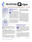
Clock
data formats, including an interface
Address
read address/write address
to an 8-bit device, such as a boot
*MSx, *SW
EPROM or UART chip (see Figure
*RD or *WR
2). The timing control signals are
Data
Read data/ write data
Figure 3—Although the data bus of the
given in Figure 3.
SHARC external port is unusual, the timing
Ack
The SHARC 21061(don’t forget
of the control signals is conventional.
Data 47-0
www.circuitcellar.com/online
CIRCUIT CELLAR ® ONLINE
December
1999
3
ADSP-21061
U5
ADDR0 13
ADDR1 14
ADDR2 16
ADDR3 17
XR88C861
U4
1 A0
3 A1
5 A2
6 A3
25 D0
16 D1
24 D2
17 D3
23 D4
18 D5
22 D6
19 D7
Data16 158
Data17 157
Data18 155
Data19 154
Data20 153
Data21 151
Data22 150
Data23 149
MS3 54
/RD 93
/WR 94
/IRQ0 238
/ACK
35
9
8
21
/CE
/RD
/WR
/INTR
Figure 4—Here you can see the necessary connections
of the XR-88C681 DUART to the SHARC external data
port.
the memory locations.
What we didn’t realize was that the
DSP kernel’s 16550 UART is mapped
to memory-select line MS2. Changing
the size of the memory banks should
have changed the addresses for the
16550 registers, cutting the communications necessary for debugging.
However, somebody at Analog
Devices was way ahead of us, and we
got lucky! The kernel assumes that
the average user code is written by the
dim-witted. The kernel accounts for
this by recalculating the effective
address of the onboard 16550 before
every access just in case the user code
changes the bank size from the default value.
Because the DUART doesn’t produce an ACK signal suitable for controlling the speed of memory
accesses, you use the internal WAIT
register to generate the six memory
wait states to synchronize the 21061
and DUART
TALKING TO THE DUART
The C program DuartAlive() (see
Listing 1) tests the bus connection. It
first sets the 21k processor interface
for 8-KB memory blocks and six wait
states. If the values stored or received
from the DUART Interrupt Vector
Register (IVR) are the same, the
DUART and SHARC are communicating.
Any register in the DUART can be
4
December
1999
accessed in C by casting a pointer to
the address of the register. Because
the EZ-SHARC g21k C compiler from
Analog Devices treats characters as a
32-bit number, care must be taken to
mask out the upper 24 bits when
reading the DUART registers.
The registers must be treated as
volatile char, which lets the compiler
know that the stored char values may
be changed by a process outside of the
C program. By assigning this, we
avoid the problem of the compiler
incorrectly replacing multiple reads
with a single read when the same
memory location is read repeatedly
without writes.
Because both mode registers have
the same address, the protocol for
accessing the DUART’s mode registers makes Listings 2 and 3 a little
confusing. After a read or write of a
value to the one-mode register, the
DUART automatically switches to
allow access to the second-mode register. The function ResetToMODE1( )
ensures that the correct register is
accessed.
With the interface tested, the next
step is to set up routines to initialize
and control the DUART. Listing 2
shows you how to initialize both the
21k interface and the DUART.
Listing 3’s routine verifies that it’s
possible to send commands from the
SHARC to the multidrop bus for receipt by the Autohelm. The full protocol for handling bus collisions is not
given.
TEST RUN
When the voice-recognition system
was put to the test, the interface component did well. Todd was able to
demonstrate that the voice-control
system was communicating via the
Listing 1—We used a dead-or-alive function test to check communications between the XR-88C681 UART
and the ADSP-21061 DSP.
#define SYSCON21K ((unsigned int *) 0x00)
// 21K processor definitions
#define BANKS8K 0xFFFF0FFF
// Set External Banks to 8K size
#define WAIT21K
((unsigned int *) 0x02)
// Wait state register
#define BANK3MASK 0xFFF07FFF
// Need 6 internally generated wait states for bank 3
#define WAIT6BANK3 0x000B8000
#define DUARTBASE 0x00406000
// DUART definitions
#define IVR ((volatile char *) 0x0C+DUARTBASE)
// Memory mapped System Configuration Register
// IVR register has 0x0C offset in the DUART
/************************************
Function: char DuartAlive(void)
Descriptions:
Returns ALIVE if the DSP can talk to DUART.
Returns DEAD if no communication
*************************************/
#define ALIVE 1
#define DEAD 0
#define TESTVALUE 0xA5
char DuartAlive(void){
*SYSCON21K &= BANKS8K;
*WAIT21K &= BANK3MASK;
*WAIT21K |= WAIT6BANK3;
// Set 21k bank size
// Clear Bank 3 bits
// 6 Waits to set
// Try to say hello to DUART
*IVR = TESTVALUE;
// Write a value to IVR
if ((*IVR) & 0xFF) != TESTVALUE) // and then bring back
return DEAD;
// Oops!
else return ALIVE;
// Success!
}
CIRCUIT CELLAR ® ONLINE
www.circuitcellar.com/online
Listing 2—The XR-88C681A DUART goes into multidrop 9-bit operation and interrupt generation when a
character is received.
// Full DUART Register Definitions
#define MODE1 ((volatile char *) 0x00 + DUARTBASE)
// Mode 1 Register Channel A
#define MODE2 ((volatile char *) 0x00 + DUARTBASE)
// Mode 2 Register Channel A
#define TXDONE ((volatile char *) 0x01+ DUARTBASE)
// Status Register Channel A
#define CLOCK
((volatile char *) 0x01+ DUARTBASE)
// Clock Select Register Channel A
#define CMD
((volatile char *) 0x02+ DUARTBASE)
// Command Register Channel A
#define INTMASK ((volatile char *) 0x05+ DUARTBASE)
// Interrupt Mask Register
#define TXHOLD ((volatile char *)0x03+ DUARTBASE)
// Transmit Hold Register
#define ResetToMODE1() *CMD = 0x10 | (*CMD & 0x0F)
// Macro to force access to Mode Register 1
void Initialize21KplusDUART(void) {
// 21k processor configuration
*SYSCON21K &= BANKS8K;
// Set bank size
*WAIT21K &= BANK3MASK;
// Clear Bank 3 bits
*WAIT21K |= WAIT6BANK3; // 6 Waits to set
// XR-88C681A Channel A Configuration
*CLOCK = 0x99;
// 4800 Baud
*CMD = 0xD5;
// TX and RX enabled
ResetToMODE1();
// Access first-mode register
*MODE1 = 0x1F;
// 9-bit char, multidrop mode
// Interrupt asserted on RXRDY
*MODE2 = 0x07;
*INTMASK = 0x02;
// Activate interrupt
}
Listing 3—Transmitting a value using multidrop protocol is a two-stage operation. First, the drop address
must be sent, then the character. The protocol for handling bus contentions is not given.
#define SENDMultiDropADDRESS 0x80
// Transmit using multidrop protocol
#define WRITEREADY 0x04
#define CLOCKED 0x08
void MultiDropSend(char value, char dropaddress) {
char temp;
ResetToMODE1( ); // Configure DUART to send 9-bit address
temp = *MODE1;
ResetToMODE1( );
*MODE1 = temp | SENDMultiDropADDRESS;
while((TXDONE & WRITEREADY) != WRITEREADY)
// Wait till DUART can send
*TXHOLD = dropaddress; /* Wait */ ;
while((*TXDONE & CLOCKED) != CLOCKED)
// Wait till value has been clocked out
/* Wait */ ;
ResetToMODE1( ); // Configure DUART to send 9-bit value
temp = *MODE1;
ResetToMODE1( );
*MODE1 = temp & ~ SENDMultiDropADDRESS;
}
while((*TXDONE & WRITEREADY)
// Wait till DUART
/* Wait */ ;
* TXHOLD = value;
while((*TXDONE & CLOCKED) !=
// Wait till value
/* Wait */ ;
www.circuitcellar.com/online
!= WRITEREADY)
can send
CLOCKED)
has been clocked out
serial link correctly with the signals
coming in at the right time.
However, the voice-recognition
system was only responding appropriately to approximately 20% of the
commands it was given. Both the
voice conditioning and speech-recognition engine components are back on
the drawing board, waiting for another
team of students to pick the project
up. Certainly, the next crew will have
an easier time as Analog Devices has
donated its Visual DSP development
simulator as well as an in-circuit
emulator. Many of the problems of
this first team were exacerbated by a
lack of debugging tools.
In the meantime, Todd’s interface
is being put to work in other projects.
It’s currently playing a significant role
in an MP3 compression/decompression.
ACKNOWLEDGEMENTS
We appreciate the help of Con
Korirus of Analog Devices University
Support and Jim Forsythe and Stan
Parker of BBD Electronics, Calgary,
the local distributor for Analog Devices, who donated a class set of
SHARC EZ-Kit Lite demo boards,
documentation, and in-circuit emulators. Rob Thompson at Raytheon
Marine, U.K. was only an e-mail away
with info on SeaTalk protocols.
Thanks to the project design team—
Stuart Bergen, Chris Leskiw, and
Sunny Sandu—for their expertise and
moral support. Thanks also to Ron
Johnston, head of Electrical and Computer Engineering, for making the
laboratory facilities available after
hours. And, last but not least, without
the help and patience of Alberta Disabled Sailing Association, this project
would have sunk. I
Mike Smith is a professor of Engineering at the University of Calgary.
He specializes in microprocessor
applications with a biomedical slant
or any project he thinks might be
interesting. You may reach Mike at
mailto:[email protected].
Todd Turner graduated in May
1999 with a B.Sc. in Electrical Engi-
CIRCUIT CELLAR ® ONLINE
December
1999
5
neering. He has returned to MCK
Communications to continue his
work with embedded systems. You
may reach Todd at
[email protected].
Steve Alvey continues to improve
the Martin 16’s control system. He’d
be pleased to hear from others who
would like to help get disabled sailors
on the water. He can be contacted at
[email protected].
SOURCES
Analog Devices DSP applications
(800) ANALOGD
(617) 329-4700
Fax: (617) 329-1241
www.analogdevices.com
Disabled Sailing Association of
Alberta
www.inventmgmnt.ab.ca/
sipandpuff/
Exar XR-88C681A DUART reference manual
www.exar.com/products/
xr88c681.html
Raytheon Marine
www.autohelm.com
Circuit Cellar, the Magazine for Computer Applications.
Reprinted by permission. For subscription information,
call (860) 875-2199, [email protected] or
www.circuitcellar.com/subscribe.htm.
6
December
1999
CIRCUIT CELLAR ® ONLINE
www.circuitcellar.com/online