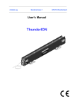
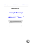
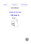
1
relstatic ag
Gublenstrasse 1
CH-8733 Eschenbach
Operating instruction
Thunder Ion Control Module
abcde
ThunderIon Control Modul
CONTENTS
Page
1. Introduction
2. Safety
3. Technical specifications
4. Installation
5. Commissioning
6. Functional check
7. Maintenance
8.Faults
9. Repair
10. Disposal
11. Spare parts
Appendix 1: Wiring diagram
Appendix 2: ThunderIon System overview
www.relstatic.ch
3
3
4
5
8
8
9
9
11
11
11
12
13
Page 2
ThunderIon Control Modul
Preface
Read the whole manual before you install and commission the product.
Follow the instructions set out in this manual to ensure proper operation of the product and to
retain your entitlement under the guarantee.
The term Control Module in this user manual refers to the ThunderION Control Module.
The terms of the guarantee are set out in the Relstatic AG General Terms and
Conditions of Sale.
1. Introduction
The Control Module forms, together with connected ThunderION anti-static bars, a system for
neutralising static electricity.
The Control Module has a switched power supply that converts mains voltage to 24 V DC to
operate a maximum of 4 ThunderION units.
LEDs on the Control Module show whether the ThunderION is switched on and whether a fault
has occurred.
The ThunderION incorporates functions for being switched on and off remotely, as well as for
remote read out of high voltage (not wireless).
2. Safety
− The Control Module is only meant for use with the ThunderION.
− Read the ThunderION user manual as well as this user manual.
− Electrical installation, maintenance and repairs may only be carried out by a skilled electrical
fitter.
− Before working on the equipment, disconnect the power supply.
− Ensure that the equipment is properly earthed (see Installation, H4).
Equipment must be earthed to ensure that it works properly and safely.
− The Control Module is protected against overload by a glass fuse.
− If changes, adjustments etc. have been made without prior consent in writing, or if nonoriginal parts have been used for repairs, the equipment loses its CE approval and will no
longer be under guarantee.
www.relstatic.ch
Page 3
ThunderIon Control Modul
3. Technical specifications
Power supply
Mains voltage
Frequency
Max. power consumption
Mains connection
100 – 240 V AC
50/60 Hz
100 W
1.8 m 3-core mains cable.
Output
Output voltage
Max. output current
Max. power output
Short-circuit protection
24 V DC
2.8 A (4x0.7 A)(4 ThunderIONs of max. length)
68 W
By 3.15 AT, 250 V AC glass fuse
Environment
Cooling
Ambient temperature
Sealing
Operating environment
Input/output connectors
Local signalling
[Power On] signalling
[Remote On] signalling
[Local On] signalling
[Bar On] signalling
[Bar Fault] signalling
I/O:
Remote On/Off
Bar Operating OK
Power source for I/O
www.relstatic.ch
Convection
0 – 50°C
IP-54
Industrial
4x connectors required for ThunderION
1x connector required for remote I/O
Green LED
Green LED
Green LED
Green LED (4x)
Red LED (4x)
Control voltage specifications:
10 V DC, 10 mA min.
30 V DC, 25 mA max.
Max. permitted value: 30 V DC, 50 mA (4x)
24 V DC, 100 mA max.
Page 4
ThunderIon Control Modul
4. Installation
4.1. Prior check
− Check whether the Control Module has been received undamaged.
− Check that the details on the packing slip correspond to the details shown on the product
received.
If you have any problems and/or if in doubt:
please contact Relstatic AG
4.2. General
Install the Control Module in the desired position within the range of the connection leads of the
ionization equipment.
Fit the Control Module so that the switch on the front is clearly visible and can be easily
reached.
−
−
−
−
−
Warning:
Before working on the equipment, disconnect the power supply.
Equipment must be earthed to ensure that it works properly and safely.
Read the ThunderION user manual as well as this user manual.
Electrical installation, maintenance and repairs may only be carried out by a skilled
electrical fitter.
Connect only the specified voltages to the control circuits.
4.3. Assembling the Control Module
− Attach the power unit using the fixing holes in the base plate.
4.4. Connection
4.4.1. Connecting the ThunderION(s)
4.4.1.1. With standard cable
Connect one end of the Control Module connecting cable to the Control Module (6-pole round
connector) and connect the other end to the ThunderION (6-pole rectangular connector).
These cables can be delivered by Simco, namely:
- 6 m Control Module connecting cable
- 12 m Control Module connecting cable
www.relstatic.ch
Art. No. 7510014480
Art. No. 7510014490
Page 5
ThunderIon Control Modul
4.4.1.2. Making your own cables
It is also possible to make the cables yourself. 6x AWG20 unshielded wire is recommended.
The connectors can be delivered separately, namely:
-6-pole (bar) Control Module connector
-6-pole ThunderION connector
Art. No. 4510140125
Art. No. 6603060120
This cable must be wired 1:1, i.e. Pin 1 to Pin 1, Pin 2 to Pin 2 etc. (See Fig. 1)
PIN
1
2
3
4
5
6
Function
+24 V
Remote ON/OFF +
HV OK open collector
HV OK open emitter
Remote ON/OFF 0V
Fig. 1 Layout of 6-pole connectors: Control Module + ThunderION
(chassis front view).
4.4.2. Connecting the Control Module
Route the mains connecting cable to the (mains) supply connection point such that it cannot
suffer mechanical damage.
− Connect up the connection cable as shown in Fig. 2, or fit a plug.
Fig. 2 Mains cable connection
www.relstatic.ch
Page 6
ThunderIon Control Modul
4.4.3. Connecting the I/O Control Module (optional)
For various remote functions, a 12-pole connector is fitted (Fig. 3).
For installation of I/O, 12x 0.12mm2 unshielded cable is recommended.
The following connectors can be delivered separately:
-12-pole (I/O) Control Module connector Art. No. 4510140130
Fig. 3 Layout of 12-pole (I/O) Control
Module connector (chassis front view).
PIN
1
2
3
4
5
6
7
8
9
10
11
12
Function
Remote on bar 1
Bar 1 operating OK
Remote on bar 2
Bar 2 operating OK
Remote on bar 3
Bar 3 operating OK
Remote on bar 4
Bar 4 operating OK
Remote on common cathode
Bar Operating OK common collector
+24 V DC out
0 V (internally connected to earth)
4.4.3.1. Connecting the remote ON/OFF function
To use the remote ON/OFF function, the switch behind the stopper must be set (see Fig. 4).
The switch must be moved to the left (remote).
Fig. 4 Remote/local switch
Attention:
-
If the remote ON/OFF function is not or no longer required:
Set the switch behind the stopper back to local
www.relstatic.ch
Page 7
ThunderIon Control Modul
Connect the remote ON/OFF power via the I/O connector 0 V must be connected to Pin 9
(remote ON common cathode)
The switch voltage must be connected to:
Pin 1 for bar 1
Pin 3 for bar 2
Pin 5 for bar 3
Pin 7 for bar 4
(see also the circuit diagrams in the appendix)
If 0 V is supplied, the corresponding ThunderION is switched off, if 10–30 V DC is supplied, the
corresponding ThunderION is switched on. This control voltage is present on the I/O connector
(Pin 11 + Pin 12), but can also be supplied externally.
4.4.3.2. Connecting Bar Operating OK
Connect Pin 10 (Bar Operating OK common collector) to the voltage to be switched (max. 30
V). (This voltage is present on the I/O connector (Pin 11 + Pin 12), but can also be supplied
externally. This voltage must be present at the open emitter of the optocoupler when the correct
output voltages are present on the ThunderIONs.
Open emitters (Bar Operating OK):
Pin 2 for bar 1
Pin 4 for bar 2
Pin 6 for bar 3
Pin 8 for bar 4
(see also the circuit diagrams in the appendix)
5. Commissioning
− Check whether all cables have been connected correctly.
− Switch on the voltage for the power unit or insert the plug into the wall socket.
− Switch on the Control Module.
6. Functional check
6.1. Remote/local switch set to local
When the Control Module is switched on, the [Power ON] LED and [Local ON] should light up.
The [Bar ON] LEDs should light up if the corresponding ThunderIONs are connected.
If a [Bar Fault] LED lights up, this means that the corresponding ThunderION is generating
insufficient or no high voltage. This may be caused by short-circuited or fouled emitters (see the
ThunderION user manual).
The "Bar Operating OK" function can be remotely controlled for each ThunderION. If it is
operating correctly, voltage is present at the Bar Operating OK outputs of the I/O connector.
www.relstatic.ch
Page 8
ThunderIon Control Modul
6.2. Remote/local switch set to remote
When the Control Module is switched on, [Power ON] and [Remote ON] should light up.
With the remote/local switch in the remote position, the ThunderION output voltage is switched
with the aid of a control voltage (10–30 V). This voltage must be supplied via the I/O connector
(see 4.4.3.1.).
If 0 V is supplied, the corresponding ThunderION is switched off and the associated [BAR ON]
LED does not light up. If 10–30 V DC is supplied, the corresponding ThunderION is switched on
and the associated [BAR ON] LED lights up.
The "Bar Operating OK" function can be remotely controlled for each ThunderION. If it is
operating correctly, voltage is present at the Bar Operating OK outputs of the I/O connector.
7. Maintenance
Keep the Control Module clean and dry.
The Control Module does not contain any parts that require maintenance.
8. Faults
Warning:
− When carrying out work on the equipment, disconnect the power supply.
− The work must be carried out by a skilled electrical fitter.
Depending on the configuration, the cause of a fault can be found in five places, namely:
-the ThunderION(s)
-the wiring between the ThunderION(s) and the Control Module
-the Control Module
-the I/O connector wiring
-peripherals connected to the I/O connector, e.g. a PLC
www.relstatic.ch
Page 9
ThunderIon Control Modul
Table 1 Summary of faults
○ [...] LED does not light up
☼ [...] LED lights up
Led status
Control Module:
○ [Power On]
Control Module:
○ [Bar ON] &
ThunderION(s):
○ [ON]
Control Module:
☼ [Bar Fault]
ThunderION(s):
☼ [Fault]
Control Module:
☼ [Bar Fault] &
ThunderION(s):
○ [Fault]
Cause
No mains voltage
Control Module switched off
Fuse in Control Module
blown
Control Module faulty
ThunderION(s) not
connected
Solution
Switch on mains voltage
Switch on Control Module mains
switch
Replace fuse (3.15 AT, 250 V)
Return Control Module for repair
Connect ThunderION(s)
Control Module - Bar
connecting cable faulty
Control Module is in remote
position; an I/O connector is
not connected
Repair connecting cable
(See Section 4.4.1.)
Place Control Module in local
position or connect I/O connector
(See Section 4.4.2.1.)
Control Module is in remote
position, Remote on Bar
contacts are not activated
Control Module is in remote
position; an I/O connector is
wrongly wired
ThunderION faulty
Control Module faulty
ThunderION(s) placed too
close to conducting parts
ThunderION(s) heavily fouled
ThunderION(s) faulty
Control Module - Bar
connecting cable faulty
Restore input signals for Remote on
Bar
(See Section 4.4.2.)
Connect I/O connector wiring
according to Section 4.4.2.
See ThunderION user manual
See ThunderION user manual
Repair connecting cable
(See Section 4.4.1.)
ThunderION(s) faulty
See ThunderION user manual
Control Module faulty
Return Control Module for repair
See ThunderION user manual
Return Control Module for repair
See ThunderION user manual
Or:
Control Module:
○ [Bar Fault] &
ThunderION(s):
☼ [Fault]
www.relstatic.ch
Page 10
ThunderIon Control Modul
9. Repair
-
Warning:
When carrying out work on the equipment, disconnect the power supply.
Repairs must be carried out by a skilled electrical fitter.
When opening the equipment, you may touch parts under hazardous voltage.
Repairs which you can carry out on your own:
-Replacing the fuse (3.15 AT, 250 V).
-Replacing/repairing the cabling.
-Replacing sealing caps for connectors and the remote/local switch.
For other repairs, Relstatic AG advises you to return the Control Module.
Pack the Control Module properly and clearly state the reason for return.
10. Disposal
Local environmental regulations apply when disposing of the equipment.
11. Spare parts
Item No.
Description
75.10.01.4480
75.10.01.4490
45.10.14.0125
45.10.14.0130
69.99.63.0315
93.70.59.3115
66.03.06.0128
6 m Control Module connecting cable
12 m Control Module connecting cable
6-pole (Bar) Control Module connector
12-pole (I/O) Control Module connector
5x 20 mm 3.15 AT fuse
Sealing cap for remote/local switch
Sealing cap for 6- and 12-pole connectors
www.relstatic.ch
Page 11
ThunderIon Control Modul
Appendix 1:
www.relstatic.ch
Control Module/PLC wiring diagram
Page 12
ThunderIon Control Modul
Appendix 2: ThunderION system overview
www.relstatic.ch
Page 13