1
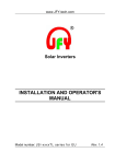
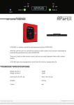
www.chinabestproducts.com
USER’S MANUAL
USER’S
MANUAL
Series INV
Pure Sine Wave Contravariant Power Supplies
_________________Inverter
Catalogue
1. Brief Introduction
1.1 Summary
1.2 Notice
2. Outline Structure
2.1 Appearance of 1KVA Inverter
2.2 Appearance of 2.3KVA Inverter
2.3 Appearance of 5.6KVA Inverter
2.4 Appearance of 8KVA-20KVA Inverter
3. Placement of Inverters
3.1 Transit and Removal
3.2 Placement
4. Fixing and Connection of Inverters
4.1. Notice
4.2 Fixing of Inverter
4.2.1 1KVA Inverter
4.2.2 Inverters over 2KVA
4.3 Selection of Dynamical Fittings
4.3.1 Selection of Wiring
4.3.2 Selection of Air Switch
www.chinabestproducts.com
1
www.chinabestproducts.com
5. Operation of Inverter
5.1 Controlling and Pointing Device
5.2 Operational Procedure
5.2.1 The First Switching on
5.2.2 Procedure of Switching Off
5.2.3 Procedure of Switching On
6. Running Indication
7. Operational Theory of Inverter
8. Explanation of Communication Interface
9. Electrical Specification
Brief Introduction of Inverter
1.1. Summary
These series of Inverters aim at needs of Office Automation and computerization by considering placement space
and location as well as noise that disturbs personnel in design. Taking small volumes, low noise with high
stabilities and easy operation as key elements, the products also maintain its consistent excellent qualities and
functions. The most outstanding point of these series of Inverters is adopting of the latest IGBT success-ratio unit
with special equipped driving ship and special designed control circuit. So applications of our Inverters will make
your precise electric equipment perform most efficiently
1.2 Notice
In order to guarantee normal performance of existing functions of the Inverters, please notice:
1. Please make sure you read this manual detailedly before using
2. Fixing must be operated as the indications in this manual
3. Operate as indicated steps
4. Avoid overloaded employ in case any trouble of the Inverters
5. Please the Inverters clean
6. Please keep this manual for reference in future
7. Fixing and maintenance should be handled by qualified personnel
8. It’s better to keep two persons on the spot while fixing Inverters
9. Construct according to safety code
10. Please do not open the machine cover to escape any person or machine from being shocked by electricity
www.chinabestproducts.com
2
www.chinabestproducts.com
Outline Structure of Inverter
2.1
Appearance of 1KVA Inverter
Fan
Control Panel
Main Switch
Battery
Interface
Output Socket
(Fig. 1)
2.2
Appearance of
2.3KVA Inverter
Fan
Main Switch
Control Panel
~
~
Communication Port
Bypass Insurance
Output Socket
Output
Switch
Insurance
Cover Board of Group
Terminal Block
Group
Block
(Fig.1.A)
www.chinabestproducts.com
3
Terminal
www.chinabestproducts.com
2.3
Appearance of 5. 6KVA Inverter
Outline Structure of Inverter
Fan
Main Switch
Control Panel
~
~
Communication
Port
Bypass Insurance
Output Insurance
Output Socket
Line Bank
Cover Board
(Fig.2.B)
2.4
Appearance of 8KVA~20KVA Inverter
Control Panel
~
~
Communication
Port
Door Lock
Fan
www.chinabestproducts.com
4
www.chinabestproducts.com
Placement of Inverter
3.Placement of Inverter
3.1 Transit and Removal
1.
Please dismantle all the connections firstly
2.
Handle with care, no hitting
3.
No inverted removal
3.2 Placement
1.
2.
Please do not set it on any rugged or declining place(Fig.5)
Please put the inverter in a ventilated place, its back and two sides should be at least 10cm from walls to
make sure unobstructed working of air orifice and air gate. (Fig. 6, Fig.7)
3. Keep the inverter from direct irradiating of sunshine (Fig.8)
4. Keep it from rain or sloppy places(Fig.9).
5. Keep it far from fire and high temperature in case the temperature gets too high (Fig. 10)
6. Keep it from space with corrosive gas
7. Temperature of running environment should be 0---+40
Placement of Invertor
(Fig.5)
www.chinabestproducts.com
5
www.chinabestproducts.com
(Fig.6)
(Fig.8)
(Fig.7)
(Fig.9)
(Fig.10)
Fixing and Connection of Invertor
4.1 Notice
1. Please follow electric principles while constructing
2. Do earthing properly
3. Test input voltage by electricity meter to check if the voltage is right
4. Stave off operation under power and make sure safe construction
5. Turn the switch on back of the inverter to “OFF”
6. Take the cover board on group terminal block away off
7. Connect input and output cables correctly in keep with marks on group terminal block and lock them after
taking insulated treatment
8. After connection, set the cover board of the group terminal block back, then the inverter can start work
www.chinabestproducts.com
6
www.chinabestproducts.com
4.2 Fixing of Inverter
4.2.1 1KVA Inverter
1KVA inverter provides two input power lines for batteries which can be inserted directly into battery
interfaces of the inverter, but please notice positive electrode and cathode of the connecting lines, they
can not be connected in opposite directions, or the inverter will de damaged. Then insert the load into
output socket of the inverter. Attention: the loading should be beyond rated ration.
4.2.2 Inverters over 2KVA
There’s a group terminal block on the back of the inverter. Battery input(1, 10), inverter output (L,N) and
earthing( ) can be connected properly according to the wiring marks. Please notice the difference of positive
electrode and cathode of batteries
输出接地端
输出零线端
输出火线端
电池输入正极
电池输入负极
输入接地端
输出接地端---Earthing Output Terminal
输出零线端---Zero Line Output Terminal
输出火线端---Live line Output Terminal
电池输入正极-Positive Electrode of Battery Input
电池输入负极-Cathode of Battery Inout
输入接地端---Earthing Inout Terminal
(Fig.11)
Warning:
1.
This machine has to be connected to the ground, and the earthing wire should not
www.chinabestproducts.com
7
www.chinabestproducts.com
be removed or cut under any condition to prevent electricity shock
a) Direct and alternating current exist between wiring terminals at the back of the
inverter, so please fit the cover board properly before start the machine
Fixing and Connection of Inverter
4.3 Selection of Dynamical Fittings
4.3.1 Selection of Wiring
4.3.2
Voltage
Power Capacity
2KVA
3KVA
5KVA
8KVA
10KVA
15KVA
4.5.2
Battery Input
5mm2
6mm2
6mm2
8mm2
10mm2
16mm2
Selection of Air Switch
Voltage
Battery Input
Power Capacity
2KVA
32A
3KVA
32A
5KVA
50A
8KVA
100A
10KVA
100A
15KVA
100A
5.1Controlling and Pointing Device
5.1.1
Output
220(V) 110(V)
2 mm2
4mm2
2
2.5 mm
6mm2
2
3.5 mm
8mm2
5.5 mm2
12mm2
2
8 mm
16mm2
10 mm2
16mm2
Output
220(V)
110(V)
15A
32A
20A
50A
32A
63A
63A
100A
100A
100A
100A
100A
Operation of Inverter
Control Panel of 1KVA Inverter
1. Mains Indicator
2. Indicator of Bypass Power Supply
3. Load Indicator
4. Indicator of Battery Electricity Quantity
5. Indicator of Invertor Working Statuc
6. Indicator of Load Power Supply
BYRASS
MAINS
INV
7. Inverter Stop Button
LOAD
FAULT
ON
www.chinabestproducts.com
8. Trouble Indicator
OFF
8
9.
Invertor Start Button
www.chinabestproducts.com
(Fig. 12 A)
5.1.2
Control Panel of Inverters over 2KVA
1. Input Indicator
:input indication of power supply of Mains(MAINS)
2. Bypass Indicator
:output indication of power supply of mains(BYPASS)
3. Output Indicator
:output indication of power supply of converter(INVERTER)
4. Indicator of Battery Electricity Quantity :if this light is on, it means electricity in the battery is being
used up (BATTERY)
5. Overloading Indicator :it shows if the user’s using electricity quantity is over rated capacity of the
inverter(OVERLOAD)
6. Fault Indicator
: to indicate troubles of inverter(FAULT)
7.LCD Display
: display figure signals, such as voltage, frequency, power, status of inverter
etc.
(1).AC:LOSS(OK)
BAT:OK(LOW)
NO OUTPUT(BYPASS OUTPUT,INVERTER OUTPUT)
(2).INPUT VOLTAGE
(5).OUTPUT FREQUENCY
(3).OUTPUT VOLTAGE
(6).BATTRY VOLTAGE
(4).INPUT FREQUENCY
(7).OUTPUT POWER
:press this button to display each working parameters of the
8.Selection Button of LCD Display
inverter circularly
:the inverter will be powered on or off if this button is pressed for
9.SwitchButton of Inverter
four seconds continuously
Remark: all indicators that relate with Mains only work when Mains are input in the inverter
Operation of Invertor
1
2
3
4
5
6
!
OUTPUT
VOLTAGE
220V ac
#2
7 (picture B)
5.2
8
9
Operational Procedure
Operations of this series are very easy and convenient, the system will run normally if you operate as
www.chinabestproducts.com
9
www.chinabestproducts.com
following steps correctly:
5.2.1
The Switching On
1.
Make sure the main switch in on “OFF” position, and no load is connecting with inverter output
2.
Check if the input power supply of the inverter is regular
3.
Turn the main switch to the position of “ON”
4.
Press the “Switch Button” on control panel and keep for four seconds, cooling fan starts, after
about 25 seconds the green contravariant indicator(-/~) will turn bright gradually
5.
If the contravariant indicator(-/~) is on, that means the inverter is working normally
6.
After the inverter is switched on successfully, the load can be connected to the inverter for using
5.2.2
1.
2.
3.
Procedure of Switching Off
Power off the load that is connected with the inverter
Press the “Switch Button” on control panel and keep for four seconds
Pull the main switch to “OFF”
Notice: do not power off the inverter if the load is not turned off
5.2.3
Procedure of Switching on
1. Pull the main switch to “ON”
2. Press the “Switch Button” on the control panel for about four seconds to turn on the inverter
3. Start the load
10
Trouble Removing of
Inverter
6.1 Running Indication
There are voice alarm of the control panel in daily use
Light on
Tu r n o f f
No
Lasting Alarm
Alarm every
4 seconds
www.chinabestproducts.com
10
Alarm every 1
second
www.chinabestproducts.com
Indicators on Control Panel
@1
~/ -
Alarming
Vo i c e
-/~
Working Status of
Inverter
Treatment @2
Normal
No
Did not press switch
button of the inverter
See Fig.15
The switch button of
inverter is not pressed
No
Power cut
Check input wire
Electricity in battery is
using up
Turn off the inverter or
the load
Electricity in battery has
been used up
Turn off the inverter
Overload
Reduce the loading
Abnormal of the inverter
Contact for
maintenance
Remark :
@ Please see Fig. 15 for indication explanation
@ for indicators of mains input and bypass, the
mains input, if the bypass indicator is on,
outputting; if the inverter is not equipped
would not be on, there is no outputting of
indicator is on
indicator is on when there is
that indicates the inverter is
with mains, the indicator
the inverter when the bypass
7.1 Normal Operation
As Fig.13, the mains supplies power to loads through commutator/inverter and static switch and charges
the battery though a charger
Mains
inverter
output controlling switch
=
~
battery
www.chinabestproducts.com
(Fig.13)
11
www.chinabestproducts.com
Direction of Communication
Interface of Inverter
8.1 Direction of Communication Port
(I)
Most computer systems are equipped with inverters to prevent systematic faults and document
damages caused by power cut. Using status of electricity is available if the computer is connected with a
communication port
(II)
(III)
Communication port can connect with a computer through D89 on the backplance to know status
of the inverter. Users should buy interface and software separately in accordance with his DOS,
WINDOWS3.1, WINDOWS95/98, WINDOWSNT, NOVELL, so the computer is possible to get
online with the inverter and display the operational condition of the inverter on screen of the
computer. If the mains is cut off, the system understands the electricity is cut, then it sends warning
message and it will perform normal switching-off procedure automatically before it records data and
closes programs once the presupposed time is up, at last it will cut off the power of the inverter
automatically. When the mains supply normally again, the inverter will recover its service
There are two kind of computer interfaces available in this inverter, one only shows status of the
inverter which fits personal computer, the other offers detailed information of the inverter, making is
suitable for stations, supervision systems etc. Standard machines only provide the first kind of
interface, software is sold separately .
1. The first computer interface: provide only mains cutting alarm, low electricity warning and powering
off of the inverter
2. The second computer interface: use RS232 communication to connect with computer and send data
continuously. Data the inverter offers includes input voltage, output voltage, output frequency, voltage
of battery and using percent of loads, internal temperature of the inverter etc.
(IV)
Hard equipment the inverter supplies: D89, see Fig.25 for its appearance
Pin signal of D89 which is provided with the inverter is as follows:
5
Pin# Function
2
3
5
RS232 Rx
RS232 Tx
Grond
www.chinabestproducts.com
I/O
Input
Output
Input
12
4 3 2
1
www.chinabestproducts.com
9
8 7 6
(Fig.14)
Electrical Specification
Specification
Rated Capacity
Mode
Voltage Stability
Frequency
Provisional
Change
Output
Overload
Performance
Load
Power
Factor
Current Wave
Crest Ratio
Input Voltage of
Direct Current
Efficiency(Full)
Noise
Protection
Indicator
Alarm
INV-1KV
INV
INV
INV
INV
INV
INV
INV
INV
A
-2KVA
-3KVA
-5KVA
-6KVA
-8KVA
-10KVA
-15KVA
-20KVA
1200W
16000W
800W
1600W
2400W
3200W
4800W
6400W
8000W
Pure sine wave,THD<3%
220V±2%
110V±2%
50Hz,60Hz±0.5%
100% load change,±4%
120%rated current,swift to bypass automatically after 5 seconds5seconds (BYPASS)
150%rated current,swift to bypass automatically after 10 cycles(BYPASS)
0.8 lagged
3:1
48V±20%
110V±20%,120V±20%
220V±15%,240V±15%,360V±15%
220V±15%,240V±15%,360V±15%
>65%
>80%
>86%
50db
55db
60db
Limit output if overloaded
Overload/short circuit protection
Rejection capacity of circnit noise is FCCA
Normal of inverter (green light) Low voltage of battery (red light)
Overload (red light)
Fault(red light)
Ring every 4 seconds after cutting of mains
Ring every second if the battery is being used up
Keep ringing if any fault or the battery is used up
9PinD Type connector(Option)
Computer Interface
Temperat
0~40
Environ ure
ment
95% if no curdling
Humidit
y
Size (W×H×Dmm)
560×280×365
555×265×570
635×270×690
Input device
Wire
Group terminal block
Remark: above information is for reference, if any change please take real products as criterions
www.chinabestproducts.com
13
550×450×1000