1
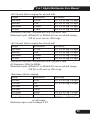
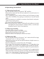
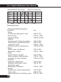
6 in 1 Digital Multimeter
User Manual
6 in 1
Sound Level
Light
Humidity
Temperature
Multimeter
Please read this manual before switching the unit on.
Important safety information inside.
6 in 1 Digital Multimeter User Manual
6 in 1 Digital Multimeter User Manual
Contents
Page
1.Introduction ........................................................................ 4
2.Safety Instructions................................................................ 5
3.Panel Description.................................................................. 6
4.Features................................................................................ 8
5.Specifications........................................................................ 8
5-1 Sound Level.................................................................... 9
5-2 Light............................................................................... 9
5-3 Temperature/Humidity.................................................... 9
5-4 Multimeter...................................................................... 10
6.Operating Instruction............................................................ 13
6-1 Measuring Sound Level................................................... 13
6-2 Measuring Humidity........................................................ 13
6-3 Measuring Light.............................................................. 13
6-4 Measuring Temperature.................................................. 15
6-5 Measuring DC Voltage.................................................... 15
6-6 Measuring AC Voltage.................................................... 15
6-7 Measuring DC Current.................................................... 16
6-8 Measuring AC Current.................................................... 16
6-9 Measuring Capacitance................................................. 17
6-10 Measuring Frequence................................................... 17
6-11 Measuring Resistance................................................... 18
6-12 Measuring Diode.......................................................... 18
6-13 Audible Continuity Test................................................. 18
6-14 Non-contact AC Voltage Test (NCV)............................... 18
7.Maintenance......................................................................... 19
3
6 in 1 Digital Multimeter User Manual
1.Introduction
The 6 in 1 digital multi-tester has been designed to combine the
functions of Sound Level Meter, Light Meter, Humidity Meter,
Temperature Meter Non-contact AC Voltage Test Meter and Digital
Multimeter.
It is an ideal multi-function Instrument with scores of practical
applications for professional and home use.
The Sound Level function can be used to measure noise in factories,
schools, offices, airports, home, etc., checking acoustics of studios,
auditoriums and hi-fi installations.
The Light function is used to measure illuminance in the field. It is
fully cosine corrected for the angular incidence of light. The light
sensitive component used in the meter is a very Stable, long life
silicon diode.
The Temperature is for use a semiconductor sensor and K type
thermocouple. This operations manual contains general information
and specification.
The digital Multimeter performs AC/DC Voltage, AC/DC Current,
Resistance measurement and Audible Continuity, Diode, Temperature
test.
4
6 in 1 Digital Multimeter User Manual
2.Safety Instructions
This meter has been designed for safe use, but must be operated
with caution. The rules listed below must be carefully followed for
safe operation.
NEVER apply voltage or current to the meter that exceeds the specified
maximum.
Input Protection Limits
Function
VDC or VAC
mA AC/DC
Maximum Input
600VDC/AC rms
500mA 660V fast acting fuse
(500mA/660V)
10A 600V fast acting fuse
A AC/DC
(10A for 30 seconds max every
15 minutes)
Frequency, Resistance, Capacitance, 600VDC/AC rms
Duty Cycle, Diode Test, Continuity
600VDC/AC rmsp
Temperature
Indicates operators must refer to the explanation in this manual.
Indicates terminals at which dangerous voltage maybe present.
5
6 in 1 Digital Multimeter User Manual
3.Panel Description
9
1
8
16
2
15
14
13
ROOM
10
11
12
3
7
4
3
6
1-Humidity & Temperature
Humidity Sensor and Semiconductor Sensor inside for Indoor.
2-LCD display
3 4/5 digits LCD display
3-Function switch
4-V / Hz% / Ω / CAP / °C input jack
5-COM input jack
6-μA / mA input jack
7-10A input jack
6
5
6 in 1 Digital Multimeter User Manual
8.Microphone
Electric condenser microphone inside.
9.Photo Detector
Long life silicon photo diode inside.
10.Hz/% button
The button at AC/DC Votalge measurement and AC/DC Current
measurement and Hz% measurement Function is availability.
11.HOLD button
The HOLD function allows the meter to “freeze“ a measurement
for later reference.Press the HOLD button to “freeze” the reading
on the indicator. The “HOLD” message will be appear in the display.
12.BACKLIGHT button
Press the backlight button for LCD light, again Press the backligh
button to exit light mode.
13.MODE button
The button to select AC or DC measurement when in A, mA, uA,
and Ω, , ranges.
14.RANGE button
The button to select AC or DC measurement when in Voltage, Ω
ranges.
15.REL button
•The relative measurement feature allows you to make measurements
relative to a stored reference value. A reference voltage, current,
Capacitor, etc. can be stored and measurements made in comparison
to that value. The displayed value is the difference between the
reference value and the measured value.
•Perform the measurement as described in the operating instructions.
•Press the REL button to store the reading in the display and the
“REL“ indicator will appear on the display.
•The display will now indicate the difference between the stored
value and the measured value.
•Press the REL button to exit the relative mode.
16.NCV indicate lamp
7
6 in 1 Digital Multimeter User Manual
4.Features
•14 functions measure Sound level, Light, Humidity, Temperature,
DC Voltage, AC Voltage, DC Current, AC Current,Resistance, Diode
and Continuity test.
•3 4/5Digital large LCD display with units of Lux, °C, %RH and dB
indication.
•Easy to use with single function switch operating, pocket size and
light weight.
•Sound level measures from 35dB to 100dB for C weighting checking
with 0.1dB resolution.
•Light measuring levers ranging from 1 Lux to 40,000 Lux.
•Humidity measurement from 30%RH to 90%RH with 1%RH resolution
and fast time response.
5.Specifications
3 4/5Digital 4000 counts LCD display with
function of Lux, °C, % and dB indication.
Automatic, ( - ) negative polarity indication.
Polarity:
“OL” mark indication.
Over-range:
” is displayed when the battery
Low battery indication: The “
voltage drops below the operating level.
3 times per second, nominal.
Measurement rate:
Operating environment: 0°C to 40°C(32°F to 104°F) at <70%RH
Storage temperature: -10°C to 60°C (14°F to 140°F) at <80%RH
One standard 9V, NEDA1604 or 6F22 battery.
Power:
170 (H)x78(W) x48(D) mm
Dimensions:
335g including holster.
Weight: Approx.:
Accuracy is given at 18°C to 28°C (65°F to 83°F), less than 70%RH.
Display:
8
6 in 1 Digital Multimeter User Manual
5-1 Sound Level
Measurement range:
Resolution:
Typical instrument
frequency range:
Frequency Weighting:
Time Weighting:
Accuracy:
Microphone:
35 to 100dB
0.1dB
30Hz to 10kHz
C – weighting
Fast
±5dB at 94dB sound level, 1kHz sine wave.
Electric condenser microphone.
5-2 Light
Measuring Range:
4000, 40,000Lux
(40,000Lux range reading x10)
Overrate Display:
Highest digit of “OL” is displayed .
Accuracy:
±5% rdg +10 dgts
(calibrated to standard incandescent
lamp at color temperature 2856k).
±2%
Repeatability:
Temperature Characteristic:±0.1% / °C
One silicon photo diode with filter.
Photo detector:
5-3 Temperature/Humidity
•K-type temperatur Measurement Range:
Range
Resolution
-4°F to 1382°F
1°F
-20°C to 750°C
1°C
Accuracy
3% of rdg ± 9dgts
3% of rdg ± 5dgts
Input Impedance: 10MΩ
Overload Protection: 250VDC or AC rms. for 400mV range and 250VDC
or 250VAC rms. for other ranges.
9
6 in 1 Digital Multimeter User Manual
•Indoor Temperature Range
Range
Resolution
0°C to 50°C
0.1°C
Accuracy
3% of rdg ± 5 dgts
•Indoor Humidity Range
Range
Resolution
33%RH to 99%RH
1%RH
Accuracy
3% of rdg ± 5 dgts
Input Impedance: 10MΩ
Overload Protection: 250VDC or AC rms. for 400mV range and 250VDC
or 250VAC rms. For other ranges.
5-4 Multimeter
•DC Voltage (Auto-ranging)
Range
Resolution
Accuracy
400.0mV
0.1mV
±1.0% of rdg ±4 dgts
4.000V
1.0mV
40.00V
10mV
400.0V
100mV
±1.5% of rdg ±4 dgts
600V
1V
Input Impedance: 10MΩ
Overload Protection: 600VDC or AC rms. for 400mV range and 600VDC
or 600VAC rms. For other ranges.
•AC Voltage (Auto-ranging except 400mV)
Range
Resolution
Accuracy
400.0mV
0.1mV
±1.5% of rdg ±15 dgts
4.000V
1.0mV
±1.0% of rdg ±4 dgts
40.00V
10mV
400.0V
±1.5% of rdg ±4 dgts
100mV
600V
±2% of rdg ±4 dgts
1V
Input Impedance: 10MΩ
Frequency Range: 50 to 400Hz
Maximum Input: 600VDC or 600VAC rms.
10
6 in 1 Digital Multimeter User Manual
•DC Current (Auto-ranging for uA and mA)
Range
Resolution
Accuracy
400.0uA
0.1uA
±1.0% of rdg ±2 dgts
4000uA
1uA
±1.0% of rdg ±2 dgts
400.0mA
100uA
±1.2% of rdg ±2 dgts
10.00A
10mA
±2.0% of rdg ±5 dgts
Overload Protection: 500mA/660V and 10A/600V Fuse
Maximum Input: 400mA DC or 400mA AC rms on uA/mA ranges,
10A dc or ac rms on 10A range.
•AC Current (Auto-ranging for uA and mA)
Range
Resolution
Accuracy
400.0uA
0.1uA
±1.2% of rdg ±2 dgts
4000uA
1uA
±1.2% of rdg ±2 dgts
400.0mA
100uA
±1.5% of rdg ±2 dgts
10.00A
10mA
±2.0% of rdg ±5 dgts
Overload Protection: 500mA/660V and 10A/600V Fuse
AC Response: 50Hz to 400Hz
Maximum Input: 400mA DC or 400mA AC rms on uA/mA ranges,
10A DC or AC rms on 10A range.
•Resistance (Auto-ranging)
Range
Resolution
Accuracy
400.0Ω
0.1Ω
±1.5% of rdg ±4 dgts
4.000kΩ
1Ω
±1.5% of rdg ±2 dgts
40.00kΩ
10Ω
400.0kΩ
100Ω
4.000MΩ
±2.0% of rdg ±2 dgts
10kΩ
40.00MΩ
±2.5% of rdg ±2 dgts
1MΩ
Overload Protection: 15 seconds maximum 250V DC or 250V AC rms,
on all ranges.
Maximum open circuit voltage: 2.8V
11
6 in 1 Digital Multimeter User Manual
•Capacitance (Auto-ranging)
Range
Resolution
Accuracy
50.00nF
±5.0% of rdg ±7 dgts
10pF
500.0nF
±3.0% of rdg ±5 dgts
0.1nF
5.000uF
1nF
50.00uF
10nF
100.0uF
±4.0% of rdg ±5 dgts
0.1uF
Input Protection: 600V DC or 600V AC rm
•Frequency (Auto-ranging)
Range
Resolution
Accuracy
5.000Hz
0.001Hz
±1.2% of rdg ±3 dgts
50.00Hz
0.01Hz
500.0Hz
0.1Hz
5.000kHz
1Hz
50.00kHz
10Hz
500.0kHz
100Hz
10.00MHz
1kHz
±1.5% of rdg ±4 dgts
Sensitivity: >0.5V RMS while <1MHz;
Sensitivity: >3V RMS while >1MHz;
Input Protection: 250V DC or 250V AC rms.
•Diode and Continuity check
Diode: Test current 1.4mA dc and open circuit voltage 2.8V DC.
Continuity: Built in Buzzer will be sound if the circuit resistance is
less than 50Ω
Overload Protection: maximum 600V DC or 600V AC rms.
12
6 in 1 Digital Multimeter User Manual
6.Operating Instruction
6-1 Measuring Sound Level
•Set the function switch to the green “dB” position.
•Remove the meter and face the microphone to sound source in a
horizontal position.
•The C-weighting curve is nearly uniform over the frequency range
from 30 to 10,000Hz, thus giving an indication of overall Sound
level.
•The Fast response is suitable to measure shout bursts and peak
values from sound source.
•The sound level will be displayed.
Note: Strong wind (over 10m/sec.) striking the microphone can cause
misreading for measurement in windy locations, a windscreen
should be used in front of microphone.
6-2 Measuring Humidity
•Humidity Measurement for indoor.
•Set the function switch to the ON position.
•Remove the meter place to the room.
•Read the %RH in the display for about two hours.
6-3 Measuring Light
•Set the function switch to the green “Lux” scale and set the range
to desired (“Lux” or “x10 Lux”) range.
•Remove the meter and face the photo detector to light source in a
horizontal position.
•Read the illuminance nominal from the LCD display.
•Over-range: If the instrument only display one “1” in the M.S.D. the
input signal is too strong, and a higher range should be selected.
•When the measurement is completed. Replace the photo detector
from the light source.
•Spectral sensitivity characteristic: To the detector, the applied photo
diode with filters makes the spectral sensitivity characteristic almost
meet C.I.E. (International Commission on Illumination) photopia
curve V (λ) as the following chart described.
13
6 in 1 Digital Multimeter User Manual
100%(Relative Sensitivity)
Spectral Sensitivity
80%
V(λ)
60%
40%
20%
0
400
500
Wavelength(nm)
600
•Recommended Illumination:
Locations
*Office
Conference, Reception room.
Clerical work
Typing drafting
*Factory
Packing work, Entrance passage
Visual work at production line
Inspection work
Electronic parts assembly line
*Hotel
Public room, Cloakroom
Reception, Cashier
*Store
Indoors Stairs Corridor
Show window, Packing table
Forefront of show window
*Hospital
Sickroom, Warehouse
Medical Examination room
Operating room
Emergency Treatment
*School
Auditorium, Indoor Gymnasium
Class room
Laboratory Library Drafting room
14
700
Lux
200 to 750
700 to 1,500
1000 to 2,000
150 to 300
300 to 750
750 to 1,500
1500 to 3,000
100 to 200
200 to 1,000
150 to 200
750 to 1,500
1500 to 3,000
100 to 200
300 to 750
750 to 1,500
100 to 300
200 to 750
500 to 1,500
6 in 1 Digital Multimeter User Manual
6-4 Measuring Temperature
Temperature Measurement for outdoor:
•Set the function switch to the green “0.1°C” position or “1°C”
position .
•Then the display will show the environment temperature reading
value °C directly.
•Insert the black plug of temperature probe the COM jack and red
plug to the “V/Hz%/Ω/CAP/°C“ jack.
•Touch the end of the temperature sensor to the area or surface of
the object to be measured. The display will show the temperature
reading value °C directly.
6-5 Measuring DC Voltage
•Insert the black test lead banana to the COM jack and red test lead
banana to the “V/Hz%/Ω/CAP/°C“ jack.
•Set the function switch to the green at DCV ranges to be used and
connect test leads connect test leads across the source or load under
measurement.
•Set the function switch at DCmV ranges to be used connect test
leads connect test leads across the source or load under measurement.
•Read LCD display. The polarity of red connection will be indicated
when making a DC measurement.
•Press the Hz% button to indicate “Hz”.
•Read the frequency in the display.
•Press the Hz% button again to indicate “%”.
•Read the % of duty cycle in the display.
6-6 Measuring AC Voltage
•Insert the black test lead banana to the COM jack and red test lead
banana to the “V/Hz%/Ω/CAP/°C“ jack.
•Set the function switch to the green at AC ranges to be used and
connect test leads connect test leads across the source or load under
measurement.
•Read LCD display. The polarity of red connection will be indicated
when making a AC measurement.
•Press the Hz% button to indicate “Hz”.
15
6 in 1 Digital Multimeter User Manual
•Read the frequency in the display.
•Press the Hz% button again to indicate “%”.
•Read the % of duty cycle in the display.
6-7 Measuring DC Current
•Insert the black test lead banana plug into the negative COM jack.
and the red test lead banana plug into the “uA/mA”or “10A” jack.
•For current measurements up to 4000uA DC, set the function switch
to the µA position and insert the red test lead banana plug into the
uA/mA jack.
•For current measurements up to 400mA DC, set the function switch
to the mA position and insert the red test lead banana plug into
the µA/mA jack..
•For current measurements up to 10A DC, set the function switch to
the yellow 10A position and insert the red test lead banana plug
into the 10A jack.
•Press the MODE button to indicate “DC” on the display.
•Remove power from the circuit under test, then open up the circuit
at the point where you wish to measure current.
•Touch the black test probe tip to the negative side of the circuit.
Touch the red test probe tip to the positive side of the circuit.
•Apply power to the circuit.
•Read the current in the display.
6-8 Measuring AC Current
•Insert the black test lead banana plug into the negative COM jack.
and the red test lead banana plug into the “uA/mA”or “10A” jack.
•For current measurements up to 4000uA AC, set the function switch
to the uA position and insert the red test lead banana plug into the
uA/mA jack.
•For current measurements up to 400mA AC, set the function switch
to the mA position and insert the red test lead banana plug into the
uA/mA jack
•For current measurements up to 10A AC, set the function switch to
the yellow10A position and insert the red test lead banana plug into
the 10A jack
16
6 in 1 Digital Multimeter User Manual
•Press the MODE button to indicate “AC” on the display.
•Remove power from the circuit under test, then open up the circuit
at the point where you wish to measure current.
•Touch the black test probe tip to the neutral side of the circuit.
Touch the red test probe tip to the “hot” side of the circuit.
•Apply power to the circuit.
•Read the current in the display.
•Press and hold the Hz% button to indicate “Hz”.
•Read the frequency in the display.
•Momentarily press the Hz% button again to indicate “%”.
•Read the % duty cycle in the display.
•Press and hold the Hz% button to return to current measurement.
6-9 Measuring Capacitance
•Set the function switch to the green CAP position.
•Insert the black test lead banana plug into the negative COM jack
and the red test lead banana plug into the “V/Hz%/Ω/Cap/°C” jack.
(If value is no zero in the display. Press the REL button to zero)
•Touch the test probe tips across the part under test.
•Read the capacitance value in the display.
•The display will indicate the proper decimal point and value.
6-10 Measuring Frequence
•Set the function switch to the Hz position.
•Insert the black test lead banana plug into the negative (COM) jack
•Insert the red test lead banana plug into the “V/Hz%/Ω/CAP/°C“ jack.
•Touch the test probe tips to the circuit under test.
•Read the frequency in the display.
•The digital reading will indicate the proper decimal point, symbols
(Hz,kHz, MHz) and value.
17
6 in 1 Digital Multimeter User Manual
6-11 Measuring Resistance
•Set the function switch to the green Ω
position.
•Insert the black test lead banana plug into the negative COM jack.
Insert the red test lead banana plug into the V/Hz%/Ω/CAP/°C jack.
•Indicate “OL” “MΩ” on the display.
•Touch the test probe tips across the circuit or part under test. It is
best to disconnect one side of the part under test so the rest of the
circuit will not interfere with the resistance reading.
•Read the resistance in the display.
6-12 Measuring Diode
•Set the function switch to the green Ω
position.
•Insert the black test lead banana plug into the negative COM jack
and the red test lead banana plug into the V/Hz%/Ω/Cap/°C jack.
•Press the MODE button to indicate “ “ and “V” on the display.
•Touch the test probes to the diode under test. Forward voltage will
typically indicate 0.400 to 0.700V. Reverse voltage will indicate “OL”.
Shorted devices will indicate near 0V and an open device will indicate
“OL” in both polarities.
6-13 Audible Continuity Test
•Set the function switch to Ω
position.
•Insert the black lead banana plug into the negative COM jack.
Insert the red test lead banana plug into the V/Hz%/Ω/CAP/°C jack.
•Press the MODE button to indicate“ “ and “Ω” on the display
•Touch the test probe tips to the circuit or wire you wish to check.
•If the resistance is less than approximately 50Ω, the audible signal
will sound. If the circuit is open, the display will indicate “OL”.
6-14 Non-contact AC Voltage Test (NCV)
•Set the function switch to the ON position.
•Remove the meter and face the NCV detector to ACV source.
•If source votalge in 50-1000V the NCV indicate lamp will light.
18
6 in 1 Digital Multimeter User Manual
7.Maintenance
Battery and Fuse Replacement
If the sign “
” appears on the LCD display, it indicates that the
battery should be replaced. Remove screws on the back cover and
open the case. Replace the exhausted battery with new batteries.
(1 x 9V battery NEDA 1604, 6F22 or equivalent)
Fuse rarely need replacement and blow almost always as a result of
the operator’s error. Open the case as and replace the blown fuse
with ratings specified.
Warning:
Before attempting to open the case, be sure that test leads have been
disconnected from measurement circuit to avoid electric shock hazard.
Replace fuse only with specified ratings:
Fuse1: F10A / 600V fast blow.
Fuse2: F500mA / 660V fast blow.
19
Rev.101217
6 in 1 Digital Multimeter User Manual