1
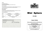
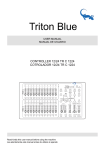
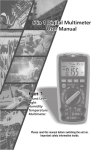
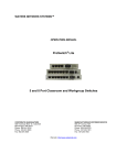
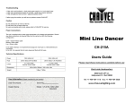
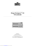
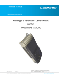
STAGE DESIGNER
TFX-24C
User Guide
Please read these instructions carefully before use
World-wide Headquarters:
3000 North 29th Ct., Hollywood, Florida, USA, FL 33020
Tel: +1-954-929-1115 Fax: +1-954-929-5560
www.ChauvetLighting.com
SCENE SETTER USER MANUAL
INTRODUCTION:
Congratulations on purchasing your new scene setter. It is a microprocessor controlled
system that is fully DMX-512 and MIDI compatible. The scene setter is a 24 channel
DMX-512 and standard MIDI controller.48 sets of program can be programmed in 4
pages and the total steps can not more than 4500. We strongly recommend that you
take time to read this manual fully before you attempt to use the controller. we are sure
that it is the most advanced unit for its size and price and it will provide you easy operation
and tremendous control power.
SPECIFICATIONS:
CONTROLLER DESCRIPTION:
31 3029
1
1
2
3
5
4
6
7
8
9
11
10
STAGE
DESIGNER
SRC-146 24CH
Dimmer Console
12
10
10
10
10
10
10
10
10
10
10
10
8
8
8
8
8
8
8
8
8
8
8
6
6
6
6
6
6
6
6
6
6
6
4
4
4
4
4
4
4
4
4
4
4
2
2
2
2
2
2
2
2
2
2
2
0
0
0
0
0
0
0
0
0
0
0
REC STEP
DIMMER
SPEED TIME
FADE TIME
UP
DOWN
DELETE
BEAT REV
CHASE REV
DARK
MODE
SELECT
2
4
13
14
15
16
17
18
19
20
21
22
23
24
5
1
2
3
4
5
6
7
8
9
10
11
12
CHASE
A DOUBLE
1-24 SINGLE
2 3
PAGE
ALL REV
ADD
KILL
4
REC
CLEAR
RECORD
REC
EXIT
SHIFT
SINGLE CHASE
MIX CHASE
SCENES
PRESET B
PRESETPARK
HOLD
STEP
SCENES
MASTER
10
10
10
10
10
10
10
10
8
8
8
8
8
8
8
8
6
6
6
6
6
6
6
6
4
4
4
4
4
4
4
2
2
2
2
2
2
2
0
0
0
0
0
0
0
10
10
0
8
8
8
8
2
6
6
6
6
4
4
4
4
4
4
6
2
2
2
2
2
8
0
0
0
0
0
10
A
6
BLIND
7
89
10MIN
SPEED
FADE
10
AUDIOLEVEL
INSTANT
.ISEC
.2s
.2s
.2s
.5s
1s
2s
5s
.5s
1s
2s
5s
1s
2s
5s
10s
10s
10s
20s
30s
30s
1m
1m
2m
1m
2m
5m
5m
MINS
SHOW
MODE
10m
MINS
20
19
18
AUDIO
5MIN
10
28
27
26
25
24
23
22
21
EDIT
REV ONE
1
REC SPEED
3
INSERT
.ISEC
2m
5m
10m
MINS
SHOW
MODE
10
10
8
8
6
6
4
4
2
2
0
0
B
HOME
TAP SYNC
FULL-ON
10 11 12 13 14 11
16
BLACK OUT
17
PAGE 1
REAR PANEL
DC INPUT
MIDI
DMX OUT
1
1=Ground
2=Data3=Data+
+
THRU
OUT
IN
2
3 4
1/4"stereo jack
LINE IN
1
3
5
REMOTE
8
1=Ground
2=Data+
3=Data-
100mV 1Vp-p
500 mA min
2
AUDIO
DMX polarity select
6
Full on
Black out
GND
7
PAGE 2
OPERATING INSTRUCTION:
RECORDING:
1. RECORD ENABLE
1) Press and hold RECORD KEY.
2) Press FLASH 1 FLASH 5 FLASH 6 FLASH 8 keys in sequence.
3) Release RECORD, the led is lighting, recording is ready.
2. ERASE ALL PROGRAMS
1) Press and hold RECORD KEY.
2) Press FLASH 1 FLASH 3 FLASH 2 FLASH 3 in sequence.
3) Release RECORD
3. CLEAR MEMORY
1) Press RECORD key, and then press REC CLEAR KEY.
2) Release RECORD and REC CLEAR at a time.
4. RECORD PROGRAM
1) Set desired channel and record it.
2) Light the relevant page led.
3) Press RECORD then press appropriate FLASH.
4) Release RECORD.
For example: create a program ,record it in the 28th SCENE.
1) clear memory.
2) light 1-24 SINGLE LED
3) set channel slider 1-24 to min. position and MASTER A to max. position.
4) move slider 1 to max. Position, press RECORD then move it to
min. Position. Continue moving other sliders until all sliders are set.
5) press PAGE key to light page 3 led.
6) press RECORD ,then press FLASH 16.
7) Release RECORD and FLASH 16, the program of 1-24 full on in sequence
is recorded in the 28th SCENE.
5. DELETE A PROGRAM
1) Press PAGE to light the desired PAGE LED.
2) Press RECORD, then press appropriate FLASH twice.
For example: to delete the 40th SCENE program .
1) press PAGE to light page 4 led.
2) press RECORD ,then press FLASH 16 twice.
3) release RECORD.
6. SCENE EDIT ENABLE
1) Press PAGE light desired PAGE led.
SCENES
2) Press MODE SELECT to light CHASE
led.
3) Press EDIT and desired scene FLASH.
4) Release EDIT and the FLASH, the relevant SCENE LED is lit and others
go out. Now editing is enable.
For example : to make the 11th SCENE program enter EDIT mode .
1) press PAGE to light PAGE 1 led.
2) press MODE SELECT to light CHASE
LED
3) Press EDIT and FLASH 23.
4) Release EDIT and FLASH 23.
SCENES
7. EXIT EDIT MODE
1) Press RECORD ,then press EXIT.
2) Release RECORD and EXIT.
8. DELETE STEP
1) In EDIT mode ,press STEP to execute the program till the step to be deleted.
2) Press DELETE . The step is deleted and the next step is executed.
9. ADD STEP
1) In EDIT mode .record the step to be inserted.
2) Press STEP to execute the program till the step you want to insert before.
10. MODIFY STEP
1) In EDIT mode. Press STEP to execute the program till the step to be modify.
2) press UP or DOWN and desired FLASH ,the output will show on display ,you feel it is ok
,release FLASH.
11. CHANGE SHOWING MODE OF DIMMER Press and hold RECORD, then press
0%or0-255 KEY.
12. SELECT AND RUN PROGRAM
1) Press MODE SELECT to light CHASE
led.
SCENES
2) Press PAGE to light the desired page led.
3) Move MASTER B slider to max. Position.
4) Move desired scene channel slider to min.,then move it up,the program is selected and
executed.
13. RUN A PROGRAM WITH REGULAR BEAT
1) Press AUDIO to extinguish AUDIO led.
2) Press PARK to light MIX MODE LED.
3) Select to run the scene program.
4) Move the SPEED slider or press TAP SYNC twice to define beat
time.
5) Press REC SPEED and the desired FLASH KEY. Then the program will be executed
with the beat time.
14. RUN A PROGRAM WITH SPEED SLIDER.
1) Press AUDIO to extinguish AUDIO led.
2) Press PARK to light MIX MODE led.
3) Select to run the scene program.
4) Move SPEED slider to SHOW MODE position.
5) Press REC SPEED, then press the appropriate FLASH.
For example: run the 14th SCENE program with the speed of 1 steps
per second, then set it to be controlled by speed slider.
1)Press MODE SELECT to light CHASE
LED.
SCENES
2)Press AUDIO to extinguish its led.
3)Press PARK to light MIX MODE LED.
4)Move all channel sliders to min. Position.
5)Move MASTER B slider to max. Position.
6)Press PAGE to light PAGE 2 LED.
7)Move the 14th channel slider to max. Position.
8)Move SPEED slider until 1.00 appear in display and SPEED LED is lit.
9)Press REC SPEED and FLASH 14, then release both keys, the 14th SCENE
program is set to run 1 step per second.
10)Move SPEED slider to SHOW MODE position. Press REC SPEED and the 14th
FLASH , then the 14th SCENE program is set to be controlled by SPEED
slider, move SPEED slider until 0.10 appears on display, the 14th program
will run with 10 steps per second.
15.SPEED SETTING
A: SLOWEST SPEED SLIDER SETTING(5 MIN)
1)Press and hold RECORD .
2)Press the 5th FLASH KEY 3 times, then release RECORD.
3)The 5 MIN LED is lit, which means that 5 MIN SPEED slider is done.
B: SLOWEST SPEED SLIDER SETTING(10 MIN)
1)Press and hold RECORD .
2)Press the 10th FLASH KEY 3 times, then release RECORD.
3)The 10 MIN LED is lit, which means that 10 MIN SPEED slider is done
16.MIDI IN SETTING
1)Press and hold RECORD
2)Press 1th FLASH KEY 3 times, then release RECORD, when CHI appears on
display, you can select MIDI IN channel from 1th FLASH to 16th FLASH.
3)After you press desired FLASH, the appropriate channel led is lit.
4)Press RECORD and EXIT to withdraw MIDI IN setting.
PAGE 4
17.MIDI OUT SETTING
1)Press and hold RECORD
2)Press 2th FLASH KEY 3 times, then release RECORD, when CHO appears on
display, you can select MIDI IN channel from 1th FLASH to 16th FLASH.
3)After you press desired FLASH, the appropriate channel led is lit.
4)Press RECORD and EXIT to withdraw MIDI OUT setting.
18.RECEIVE FILE DUMP
1)Press and hold RECORD
2)Press 3th FLASH KEY 3 times, then release RECORD, when IN appears on
display, it is ready to receive file dump.
3)All other operations are void when receiving file dump. It will
withdraw receiving file dump automatically when receiving is over or
mistakes is occurred. Power on after power off also pause receiving file dump.
19.send file dump
1)Press and hold RECORD
2)Press 4th FLASH KEY 3 times, then release RECORD, when OUT appears on
display, it is ready to receive file dump.
3)All other operations are void when receiving file dump. It will
withdraw sending file dump automatically when sending is over or
mistakes is occurred. Power on after power off also pause receiving file dump.
20. DETAILED DESCRIPTION
1)FADE TIME: The period that output varies from full dimmer to zero or
from zero dimmer to full dimmer.
2)SINGLE MODE: SCENE program is executed one by one and the N0.is showing
on display. Its speed is controlled by SPEED slider.
3)MIX MODE : All selected program are executed synchronously, each is
allowed to have respective chasing speed.
4) When CHASE
LED is lit, SCENES
you can select scene program using
PRESET B channel sliders. BLIND one of PRESET B channels, the
appropriate channel slider together with MASTER A slider control its
output, and the maximum dimmer of the program is maintained until you
HOME the channel.
5) FADE TIME & SPEED TIME INDICATIONS
A: when time is more than 1 minute, the indication includes two dots.
For example:1 minute past 15 second, indicate 1.15.
Half past 4 minute, indicate 4.30.
10 minute, indicate 10.0.
B: when time is less than 1 minute, the indication has one dot only.
For example:11.5 second, indicate 11.5
1.2 second , indicate 1.2
0.55 second ,indicate 0.55
6) transmit and receive file
A: open loop mode:
TRANSMITTER
MIDI OUT
RECEIVER
MIDI IN
PAGE 5
B: closed loop mode:
TRANSMITTER
MIDI OUT MIDI IN
RECEIVER
MIDI OUT MIDI IN
NOTE: when sending file dump in open loop mode, you should set
up receiving mode for the receiver, otherwise receiving is
disable
7) When the power voltage is too low ,the display show LOP, now you should
check whether the power is OK. It is normal that LOP is appeared for a
short while just after power is turned on.
20. MIDI RUN
1) If MIDI data is not received within 10 minutes, the channel and program
turned on by MIDI will be cleared.
2) When sending or receiving file dump, the device ID is 55H. All
information (include System Exclusive)is sent or received in file dump.
You can send SCENE program to storage or another unit, you can also
receive SCENE program from storage or another unit.
3) this unit sends or receives NOTE information ,relevant functions is as
follows:
NOTE NUMBER
22-69
70-93
94
95
96
97
98
99
100
101
102
VELOCITY
PROGRAM MASTER
CHANNEL DIMMER
FUNCTION
TURN ON/OFF PROGRAM 1-48
TURN ON/OFF CHANNEL 1-24
FULL ON
DARK
HOLD
TURN ON/OFF AUDIO CHASE
CHASE SCENES
DOUBLE
PRESET MODE
SINGLE
PRESET MODE
STEP CHANGE
BLACK OUT
Replacing Fuses
If the unit does not function when plugged in ie. items plugged into unit do not operate, then it is likely that a fuse has
blown.
Unplug unit before attempting to replace fuses.
In order to replace the fuse, unscrew the “Fuseholder Cover” to reveal the fuse.
The unit has a label attached which indicates the correct fuse rating or you may refer to the Technical Specifications
section of this guide. It is most important that replacement fuses are of the correct rating.
Failure to use the correct fuse could damage the unit beyond economic repair.
the fuseholder and the screw cap replaced. It is now safe to plug the unit back in.
Cleaning
The body of the unit may be cleaned with a soft damp cloth. We recommend internal cleaning be carried out by a fully
qualified technician.
Maintenance & Servicing
Work on internal parts should be carried out by a qualified technician. Removal of any covers other than the
“Fuseholder” is considered a breach of warranty an will not be covered under any such agreement unless authorized by
CHAUVET.
Troubleshooting
• If the unit is not functional - check that unit is fully plugged in and then check fuses.
No user serviceable parts inside, please refer to CHAUVET for service.
USA
Technical Assistance: 1-800-762-1084 (954) 929-1115
E-Mail [email protected]
POWER
120V~/60Hz / 230V~50Hz
INTERNAL FUSE
5mm x 20 mm F500mA 250v
DIMENSION
19in x 10.4in x 3.3in
WEIGHT
463mm x 254mm x 81mm
7.92lbs / 8.14kg
User Information (Please complete for your records)
Date Purchased:
Dealer Stamp
/
/
Serial No: ________________
Model: TFX-24C