1
Modbus Master Driver
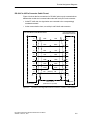
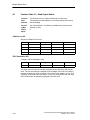
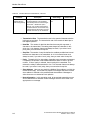
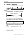
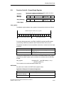
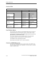
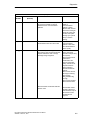
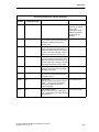
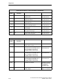
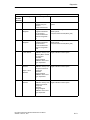
: Half-Duplex (RS422) Four-Wire Operation In this operating mode, data are
sent via the transmission line T(A),T(B) and received via the receiving line
R(A),R(B). Error handling is carried out in accordance with the function set at
the Driver Operating Mode parameter (Normal or Interference Suppression).
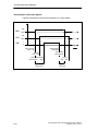
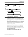
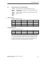
: Half-Duplex (RS485) Two-Wire Operation In this operating mode, the driver
switches the 2-wire receiving line R(A),R(B) of the interface from send to
receive operation. In this operating mode, all recognized transmission errors
and/or BREAK before and after receive messages are ignored. BREAK level
during message pauses is also ignored. The beginning of the receive message
from the slave is recognized by means of the correctly-received slave address.
The setting R(A) 0V, R(B) 5V (High) is recommended as the preset for the
receiving line.
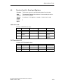
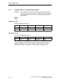
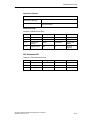
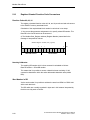
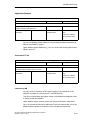
: Half-Duplex Receive Line Initial State This parameter specifies the initial
state of the receive line for RS-422 and RS-485 modes. It is not used for
RS-232C mode.
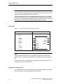
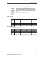
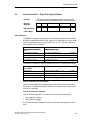
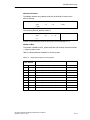
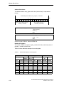
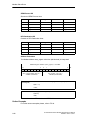
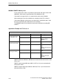
Presetting of the Receiving Line:
Presetting R(A) 5V, R(B) 0V (BREAK)
The two-wire line R(A),R(B) is preset by the module as follows:
R(A) ----> +5V, R(B) ----> 0V
(VA -- VB ² +0.3V).
This means that BREAK level occurs on the module in the event of a line break.
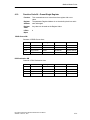
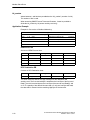
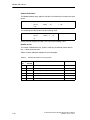
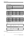
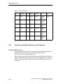
Presetting R(A) 0V, R(B) 5V (High)
The two-wire line R(A),R(B) is preset by the module as follows:
R(A) ----> 0V, R(B) ----> +5V
(VA -- VB ± --0.3V).
This means that HIGH level occurs on the module in the event of a line break
(and/or when it is idle, that is, when no slave is transmitting). The line status
BREAK cannot be recognized.
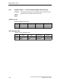
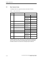
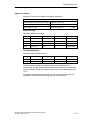
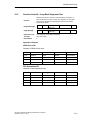
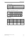
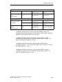
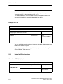
: Transmission Rate The maximum transmission rate is the speed of data
transmission in bits per second (bps). The maximum transmission rate of the
module is 38400 bps in half-duplex operation.
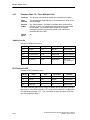
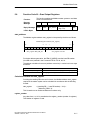
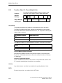
: Data Bits The amount of data bits describes how many bits represent a
character to be transmitted. The setting must always be 8 data bits. An 11-bit
character frame must always be used; if you select “none” parity, then you must
select 2 stop bits.
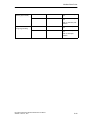
: Stop Bits The amount of stop bits defines the smallest possible time interval
between two characters to be transmitted. An 11-bit character frame must
always be used; if you select “none” parity, then you must select 2 stop bits.
: Parity The parity bit is for data safety. Depending on parameter assignment, it
completes the amount of transmitted data bits to either an even or an odd
number. If “none” parity is selected, then no parity bit is transmitted. This
reduces the safety of data transmission. An 11-bit character frame must always
be used. If you select “none” parity, then you must select 2 stop bits.
ET 200S Serial Interface Modbus/USS Module User Manual
2809295 March 15, 2001
4-13