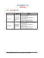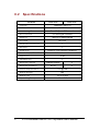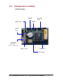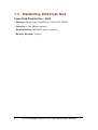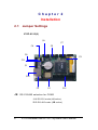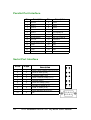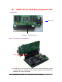
1
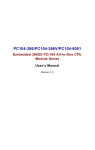
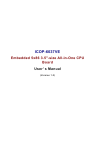
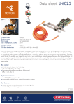
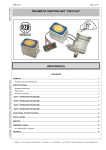
ICOP-6015 ICOP-6016 Embedded 386SX CPU Tiny Board Series User’s Manual (Version 1.1) Copyright Notice This document is copyrighted, 2000 by ICOP Technology Inc. All rights are reserved. The information in the manual is subject to change without notice in order to improving products. No part of this manual may be reproduced, copied, translated or transmitted in any form or by any means without the prior written permission of the manufacturer. ICOP Technology Inc. assumes no responsibility for any inaccuracies that may be contained in this document. ICOP Technology Inc. makes no commitment to update or to keep current the information contained in this manual. Copyright 2000 by ICOP Technology Inc. All rights reserved. Ver.1.0 2000, Printed in Taiwan Trademarks Acknowledgments All brand names and trademarks are the properties and registered brands of their respective owners. ii Table of Contents Chapter 0 0.1 0.2 0.3 Packing List .............................................................. 1 Specifications ........................................................... 2 Component Location ................................................. 3 Chapter 1 1.1 1.2 1.3 1.4 Introduction Features .................................................................... Specifications ........................................................... DiskOnChip 2000 Flash Disk ..................................... Network Interface ...................................................... Chapter 2 2.1 2.2 2.3 Startup 4 5 6 7 Installation Jumper Settings ........................................................ 8 Connectors ................................................................ 9 DiskOnChip/Flash Disk ............................................10 2.3.1 Setup a DiskOnChip ® 2000 Flash Disk ..................... 10 2.3.2 Setting up a Flash Disk.............................................. 12 2.4 2.5 Watchdog Timer .......................................................13 General Purpose I/O .................................................20 Chapter 3 3.1 3.2 Network Interface Introduction..............................................................22 Software Support .....................................................22 Appendix A. Pin assignment IDE Interface Connector ................................................... 23 Parallel Port Interface ....................................................... 24 Serial Port Interface........................................................... 24 Keyboard and PS/2 Mouse Connector ............................ 25 16-bit General Purpose I/O ............................................... 25 ISA Bus Connector ............................................................. 26 B. ICOP-2710 VGA Development Kit………………….. 27 iii Warranty iv Chapter 0 Startup 0.1 Packing List Product Name ICOP-6015 ICOP-6016 Function Embedded 386SX Tiny Board with LAN Embedded 386SX Tiny Board with I/O Package ICOP-6015 Embedded 386SX CPU Tiny Board with LAN Utility and Drivers Diskette x 1 RS232 cable x 2 Printer cable with bracket x 1 AT KB / PS2 Mouse Y-cable x 1 ICOP-6016 Embedded 386SX CPU Tiny Board with I/O Utility and Drivers Diskette x 1 RS232 cable x 2 Printer cable with bracket x 1 AT KB / PS2 Mouse Y-cable x 1 ICOP Embedded 386SX CPU Tiny Board User's Manual 1 0.2 Specifications Feature Chipset ICOP-6015 DM&P(ALi) M6117D AMI BIOS BIOS Watchdog Timer ICOP-6016 From 30.5µs to 512 seconds Bus Interface ISA bus signal interface Memory 4MB (up to 8MB)onboard I/O Chip ALi 5113 Keyboard Connector 1 IDE port 1 Serial Port RS232 X 2,(or RS232X1,RS485X1) 1 DiskOnChip / Flash Disk 16 Bit Digital I/O 1 Parallel Port Network Chipset Network Interface Power Requirement Board Weight 2 Realtek 8019AS X RJ-45 X +5V @0.4A 80g Board Size 100 X 66 mm Operating Temperature -20 ~ +60°C ICOP Embedded 386SX CPU Tiny Board User's Manual 0.3 Component Location ICOP-6015(6) COM2 GND/+5V Parallel Port COM1 GPIO Cont. Ethernet RJ-45 (Only on ICOP-6015) Keyb. Cont. IDE Port ISA Bus ICOP Embedded 386SX CPU Tiny Board User's Manual 3 Chapter 1 Introduction 1.1 Features Tiny-size (100x66 mm) Embedded CPU Modules 8-bit ISA-bus signal interface DM&P (ALi) M6117D Embedded CPU, 100% compatible with 386SX40 CPU 4MB (up to 8MB) EDO RAM onboard One Enhanced IDE Port One Bi-directional Parallel Port RS-232/485 interface Watchdog timer 16-bit GPIO connector onboard Socket for Flash or DiskOnChip Onboard AT-keyboard header Onboard Ethernet, compatible with NE2000 (Note 1) Single voltage +5 V power connector Operating temperature from –20 • +60• Flexble OEM/ODM design Note 1: only for ICOP-6015 series 4 ICOP Embedded 386SX CPU Tiny Board User's Manual 1.2 Specifications • Embedded CPU : DM&P(Ali) M6117D is an implementation of an INTEL compatible 386SX-40 CPU, Realtime clock, a watchdog timer and ALi’s M1217B chipset • BIOS: Y2K compliant AMI system BIOS • DRAM Memory: 4MB (up to 8MB) EDO DRAM onboard • Bus Interface: ISA bus signal interface • Data Bus: 16-bit • Bus Speeds: PC/104 - 8 MHz (above values are defaults, bus speeds are programmable up to 16 MHz) • DMA Channels: 7 • Interrupt Levels: 15 • Watchdog Timer: generates either a RESET, NMI or an IRQ when your application loses control over the system. Optionally the watchdog can trigger a user specified interrupt. The watchdog is configurable from 30.5 µs to 512 seconds (in 30.5 µs segments) • Real-time Clock: included in M6117D with onboard lithium battery backup for 10 years of data retention. CMOS data backup of BIOS setup and BIOS default. High Speed Multi I/O • Chipse : ALi 5113 or SMS CFDC37C669 • Serial ports: Supports high speed RS-232 port, high speed RS-232/485 port (jumper selectable). Both with 16C550 UART and 16 byte FIFO. BIOS enabled/ disabled • Bi-directional Parallel Port: supports SPP, EPP and ECP mode. BIOS enabled/disabled Environmental and Power • Power Requirements: single voltage +5 V • Board Dimensions: 100 (L) x 66 (W) mm. • Board Weight: 80 g • Extended Operating Temperature: -20~+60 °C ICOP Embedded 386SX CPU Tiny Board User's Manual 5 1.3 DiskOnChip 2000 Flash Disk Flash Disk DiskOnChip ® 2000 • Package: Single Chip FlashDisk in 32-pin DIP JEDEC • Capacity: 1-144 MByte capacity • Data Reliability: ECC/EDC error correction • Memory Window: 8 Kbyte 6 ICOP Embedded 386SX CPU Tiny Board User's Manual 1.4 Network Interface • Chipset: Realtek 8019AS single chip • Type: 10BASE-T • Connectors: onboard RJ-45 connectors • Monitoring LEDs: network ready indicator, network activity indicator • Compatibility: NE2000 ICOP Embedded 386SX CPU Tiny Board User's Manual 7 Chapter 2 Installation 2.1 Jumper Settings ICOP-6015(6) J6 J7 J4 J5 J8 J9 J11 J1 J10 J3 J2 J12 J9: RS-232/485 selection for COM2 1-2: RS-232 mode (J6 active) 2-3: RS-485 mode (J8 active ) 8 ICOP Embedded 386SX CPU Tiny Board User's Manual 2.2 Connectors J1 20-pin header for 16-bit GPIO J2 64-pin ISA bus J3 5-pin keyboard connector J4 +5V Power connector J5 10-pin box header connector for COM1 RS-232 J6 10-pin box header connector for COM2 RS-232 J7 Printer Port J8 2-pin COM2 RS-485 connector J10 LAN RJ45 connector (ICOP-6015 only) J11 For external speaker J12 44-pin header for IDE port ICOP Embedded 386SX CPU Tiny Board User's Manual 9 2.3 DiskOnChip/Flash Disk 2.3.1 Setup a DiskOnChip ® 2000 Flash Disk Installation Instructions 1. Make sure the ICOP-601X is powered OFF 2. Plug the DiskOnChip 2000 device(s) or Flash Disk into its socket. Verify the direction is correct (pin 1 of the DiskOnChip 2000 is aligned with pin 1 of the socket) 3. Set address for both DiskOnChip and Flash Disk devices as below instructions: Step1: Enter to AMI BIOS Setup Utility while system power on Step2: Enter to “Advanced Chipset Setup” Step3: Select “GPCS Function” to “Enable” (For DiskOnChip) Step4: Setect “GPCS0 Command” to “MEMR/W 8bit” Step5: Select “GPCS0 Start Address” to “0C8000 HEX” Step6: Select “GPCS0 Size” to “8 KBYTE” (goto Step 10) (For Flash Disk) Step4: Setect “GPCS0 Command” to “MEMR/W 8bit” Step5: Select “GPCS0 Start Address” to “0E0000 HEX” Step6: Select “GPCS0 Size” to “64 KBYTE” Step7: Select “GPCS1 Command“ to “IOW 8bit” Step8: Select “GPCS1 Start Address” to “000100 HEX” Step9: Select “GPCS1 Size” to “2 BYTE” Step10: Save changed and exit. 4. Power up the system 5. During power up you may observe the messages displayed by the DiskOnChip 2000 when its drivers are automatically loaded into system’s memory 6. At this stage the DiskOnChip 2000 can be accessed as any disk in the system 7. If the DiskOnChip 2000 is the only disk in the system, it will appear as the first disk (drive C: in DOS) 8. If there are more disks besides the DiskOnChip 2000, the DiskOnChip 2000 will appear by default as the last drive, unless it was programmed as 10 ICOP Embedded 386SX CPU Tiny Board User's Manual first drive. (please refer to the DiskOnChip 2000 utilities user manual) 9. If you want the DiskOnChip 2000 to be bootable: a - copy the operating system files into the DiskOnChip by using the standard DOS command (for example: sys d:) b - The DiskOnChip should be the only disk in the systems or should be configured as the first disk in the system (c: ) using the DUPDATE utility For more information on DiskOnChip2000 technology, visit M-Systems Web site http:// www.m-sys.com where you can find Utilities Manual, Data Sheets and Application Notes. In addition, you can find the lasted DiskOnChip 2000 S/W Utilities. ICOP Embedded 386SX CPU Tiny Board User's Manual 11 2.3.2 Setting up a Flash Disk Before you can use the Flash disk, you will have to initialize it by using a software utility called “PC104.EXE”. This program can be found in the subdirectory “Driver and Utility” of ICOP CD-Rom. - run PC104.EXE (this is a DOS command line utility) ICOP-601X FLASH disk initialize program V1.0 FLASH manufacturer : (1)ATMEL (2)SST Input manufacturer number (1,2) : 1 Input quantity of FLASH (1,2) : 2 Simulation disk: (1)DISK-A (2)DISK-B (3)DISK-C (4)DISK-D Input manufacturer number (1,2,3,4) : 1 FLASH-DISK initialize finish. (Text in bold should be entered by user) - After running the PC104.EXE configuration program reboot the system, while holding down the left “Ctrl” key. This will bring you to the “Flash Disk Utility” - “CHANGE CURRENT DISK NUMBER” lets you select the drive you want to assign to the disk, either A, B, C or D - “CHANGE FLASH DISK SIZE” lets you select the amount of Flash chips that are onboard. - make selections and reboot the system after closing the program Your disk can now be formatted and setup with normal DOS commands such as FORMAT, FDISK, COPY, SYS etc. Note : when assigning the solid state disk as either C or D, you first have to run FDISK before formatting the drive ! PRESS ESC KEY QUIT THIS PROGRAM 12 ICOP Embedded 386SX CPU Tiny Board User's Manual 2.4 Watchdog Timer The watchdog timer uses a 32.768 KHz frequency source with a 24-bit counter. Its time range stretches from 30.5 ms to 512 sec. with a resolution of 30.5 ms. When the watchdog times out a System RESET, NMI or IRQ can be invoked. Watchdog timer control and the 24-bit counter itself occupy 6 consecutive 8-bit address locations. When functioning properly the system resets the watchdog timer periodically to prohibit that it times out. If the watchdog timer times out, it will RESET the system, or generate and NMI or IRQ, depending on its configuration. Watchdog or System Timer Another great application is to generate a periodic IRQ signal. Under DOS environment, the 8254, system timer 0, will generate IRQ0 every 54.9 ms. The watchdog is like system timer 0. It can be programmed to periodically generate a configurable IRQ. It may be clear that the selected IRQ, will be no longer available to the system. Configuring the Watchdog Timer in the BIOS The M6117D watchdog configuration register can be controlled by software or can be setup in the BIOS. To do so go to BIOS Setup’s “Advanched Chipset Setup” Watchdog Function = Enable/Disable Watchdog Signal = RESET, NMI or IRQ 3/4/5/6/7/9/10/11/12/14/15 Watchdog Timer = 1/2/4/8/16/32/64/128/256/512 Seconds The BIOS setup only offers a limited amount of time-out values. More a hiher resolution of timeout values refer to the next paragraph “Configuring the Watchdog Timer by Software” Note that in case of using the BIOS setup, the watchdog starts counting the moment it passes the BIOS setup. This means that if you set the time-out period to 1 second, the system will keep rebooting before being able to load operating system or software ! After you have finnished configuring you watchdog timer read “Timeout Status & Reset - INDEX 3CH” on page 12 and look at the example on page 15 to find out how to priodically reseting the timeout status to prevent the watchdog timer from invoking a RESET, NMI or IRQ. Configuring the Watchdog Timer by Software Chipset configuration registers ICOP Embedded 386SX CPU Tiny Board User's Manual 13 The M6117D configuration register INDEX 37H, 38H, 39H, 3AH, 3BH, 3Ch are used to control the watchdog functions and/or display its current status. Enable/Disable watchdog - INDEX 37H Bit Value Action 7 reserved Do not modify the value of these bits! 6 0 Disable watchdog timer 1 Enable watchdog timer Other function Do not modify the value of these bits! 5-0 Watchdog time out action - INDEX 38H Bit Value Action 7-4 0000 No output signal 0001 IRQ3 0010 IRQ4 0011 IRQ5 0100 IRQ6 0101 IRQ7 0110 IRQ9 0111 IRQ10 1000 IRQ11 1001 IRQ12 1010 IRQ14 1011 IRQ15 1100 NMI 1101 System RESET 1110 No output signal 1111 No output signal 3-0 Other function Do not modify the value of these bits! 14 ICOP Embedded 386SX CPU Tiny Board User's Manual Watchdog timer - INDEX 39H, 3AH, 3BH Index 3Bh 3Ah 39h Bits D7……D0 D7……D0 D7……D0 counter [VSB……………. …………………... ………..LSB] For example Index 3Bh 3Ah 39h Time out 00h 00h 01h 30.5µs 00h 00h 02h 61µs 00h 01h 00h 7.8 ms 00h 02h 00h 15.6 ms 01h 00h 00h 2s 02h 00h 00h 4s FFh FFh FFh 512 s Timeout Status & Reset - INDEX 3CH Bit Value Action 7 0 Timeout has not occurred 1 Timeout has occured 1 Reset timer 0 Has no meaning 6 5-0 Other function, do not modify these bits Programming the watchdog To perform any operation on the M6117D configuration registers you always have to unlock first and lock the registers afterwards Unlock configuration register Lock configuration register mov al, 013h mov al, 013h out 22h, al out 22h, al ICOP Embedded 386SX CPU Tiny Board User's Manual 15 nop nop nop nop mov al, 0c5h mov al, 000h out 23h, al out 23h, al nop nop nop nop Read the value of a configuration register For example, read INDEX 3Ch : Unlock configuration register mov al, 03ch out 22h, al nop nop in al, 23h nop nop push ax Lock configuration register pop ax ;AL - result Write data to configuration register For example, write 0FFh to INDEX 3Bh : Unlock configuration register mov al, 03bh out 22h, al nop nop mov al, 0ffh out 23h, al 16 ICOP Embedded 386SX CPU Tiny Board User's Manual nop nop Lock configuration register Watchdog Program Example We use the following sequence to initialize the watchdog timer: (1) Unlock configuration register. (2) Disable watchdog timer by setting INDEX 37H Bit 6 to ‘0’. (3) Set the expected counter value to INDEX 3BH, 3AH, 39H. (4) Select timeout action from INDEX 38H Bit 7-4. (5) Enable watchdog timer by setting INDEX 37H Bit 6 to ‘1’. (6) Lock configuration register. Example: Set timeout to 128 sec to generate a system RESET. ; Please use MASM to compiler the following program ; Execute under DOS environment dosseg . model small . stack 100h .code main proc mov ax, 0c513h ; Unlock config. register call writechip mov ax, 03737h ; Disable watchdog timer call readchip and al, 10111111b xchg ah, al call writechip mov ax, 0403bh ; Set the expected counter ; value call writechip ; to [400000h] ICOP Embedded 386SX CPU Tiny Board User's Manual 17 mov ax, 0003ah ; 30.5*sec*400000h= 128 sec call writechip mov ax, 00039h call writechip mov ax, 03838h ; Select “system reset” as ; timeout action call readchip and al, 00001111b or al, 11010000b xchg ah, al call writechip mov ax, 03737h ; Enable watchdog timer call readchip or al, 01000000b xchg ah, al call writechip mov ax, 00013h ; Lock config. register call writechip mov ax, 04c00h int 21h main endp readchip proc out 22h, al nop nop in al, 23h nop nop 18 ICOP Embedded 386SX CPU Tiny Board User's Manual ret readchip endp writechip proc out 22h, al nop nop xchg ah, al out 23h, al nop nop xchg ah, al ret writechip endp end main Reset watchdog timer Resets the watchdog timer periodically to prevent timeout. mov ax, 0c513h ; Unlock configuration ; register call writechip mov ax, 03C3Ch ; Reset watchdog timer ; counter call readchip or al, 00100000 ; The counter is reset at xchg ah, al ; out 23h, al call writechip mov ax, 00013h ; Lock configuration ; register call writechip (the above code uses readchip and writechip procedures) ICOP Embedded 386SX CPU Tiny Board User's Manual 19 2.5 General Purpose I/O M6117D supports 16 independent GPOs and GPIs. This group of GPOs does not need external 74LS373 to latch as generate purpose output. Also this group of GPIs do not share signals with the ISA data bus, so no external 74LS245 is required either. At boot time the state of the GPIO ports can be set in the BIOS. Go to BIOS Setup’s “Advanched Chipset Setup” GPIO Sample Program ; Please use TASM to compiler the following program. ; Execute under DOS environment. ; .286 .model small .code mov al,13h ; Unlock 6117D configuration register. out 22h,al ; mov al,0c5h ; out 23h,al ; mov al,4eh ; Enable GPIO[7-0] is output pin. out 22h,al ; mov al,0ffh ; If AL fill “FF”, then ; GPIO[7-0] set as output pin. out 23,al ; User can be set logic “1” ; of OUT direction. mov al,4fh ; Enable GPIO[15-8] is input pin out 22h,al ; mov al,00 ; If AL fill “00”, then ; GPIO[15-8] set as input pin. 20 ICOP Embedded 386SX CPU Tiny Board User's Manual out 23h,al ; User can be set logic “0” ; of IN direction. mov al,47h ; Output data port. out 22h,al ; mov al,55h ; Example data out value is 55h, ; to output pin out 23h,al ; GPIO[7-0]. So user can ; repeat this loop. mov al,46h ; If GPIO[7-0] is set input direction, then data out 22h,al ; input port is 46. in al,23h ; Example data input value ; from data input GPIO[7-0] mov al,4ch ; Input data port out 22h,al ; in al,23h ; Read data from GPIO[15-8] ; into AL register. mov al,4dh ; If GPIO[15-8] is set output ; direction, then data out 22h,al ; output port is 4dh. mov al,55h ; output data value is 55h. out 23h,al ; Example data output value ; to data input GPIO[15-8] ....... continue program end ICOP Embedded 386SX CPU Tiny Board User's Manual 21 Chapter 3 Network Interface 3.1 Introduction The Realtek RTL-8019AS 10Mbps Ethernet controller board supports both 10BASE-T and Coax 10Base-2 ‘BNC’ connectors, and allows direct connec-tion to your 10Mbps Ethernet based Local Area Network for full interaction with local servers, wide area networks such as the Internet. I/O and IRQ settings can be done by software with the supplied utility software, or it can be set for Plug and Play compatibility. The controller supports : Full-Duplex Ethernet function to double channel bandwidth, auto media detection. 3.2 Software Support On-board EEPROM (93C46) programming Setup/Diagnostic program for DOS Help utility for easy installation RPL boot ROM for Novell Netware, Microsoft NT NDIS2 (DOS,OS/2,Lantastic,WFW3.1¡K¡K) NDIS3,NDIS4,NDIS5 for WIN95,98,NT3.51,4.0,5.0,WFW3.11 Netware 16-bit ODI driver for DOS,OS/2 and 32-bit ODI driver for Netware 3.x,4.x,5.0 Server Packet driver for UNIX Client SCO Unix driver Linux driver All operating systems that support standard NE2000 22 ICOP Embedded 386SX CPU Tiny Board User's Manual Appendix A. Pin assignment IDE Interface Connector Pin 1 3 5 7 9 11 13 15 17 19 21 23 25 27 29 31 33 35 37 39 41 43 Description Reset Data 7 Data 6 Data 5 Data 4 Data 3 Data 2 Data 1 Data 0 GND N/C IOW # IOR # N/C N/C Interrupt SA1 SA0 HDC CS0 HDD Active Vcc GND Pin 2 4 6 8 10 12 14 16 18 20 22 24 26 28 30 32 34 36 38 40 42 44 Description GND Data 8 Data 9 Data 10 Data 11 Data 12 Data 13 Data 14 Data 16 N/C GND GND GND BALE-Default GND-Default IOCS16-Default N/C SA2 HDC CSI # GND Vcc N/C ICOP Embedded 386SX CPU Tiny Board User's Manual 23 Parallel Port Interface Pin Description Pin Description 1 Strobe 2 Data 0 3 Data 1 4 Data 2 5 Data 3 6 Data 4 7 Data 5 8 Data 6 9 Data 7 10 Acknowledge # 11 Busy 12 Paper Empty # 13 Printer Select 14 Auto Form Feed # 15 Error # 16 Initialize # 17 Printer Select In # 18 GND 19 GND 20 GND 21 GND 22 GND 23 GND 24 GND 25 GND 26 NC Serial Port Interface 10- Pin D-Type 1 1 2 2 3 3 4 4 5 5 6 6 7 7 8 8 9 9 10 X 24 Description Data Carrier Detect (DCD)/5V/12V Receive Data (RXD) Transmit Data (TXD) Data Terminal Ready (DTR) Ground (GND) Data Set Ready (DSR) Request to Send (RTS) Clear to Send (CTS) Ring Indicator (RI)/5V/12V NC 1 2 3 4 5 6 7 8 9 10 ICOP Embedded 386SX CPU Tiny Board User's Manual Keyboard and PS/2 Mouse Connector Clock 1 Note for Keyboard: Data 2 No Connection 3 Pin1: KBCLK Pin2: KBDATA GND 4 Power 5 Clock 1 Data 2 No Connection 3 GND 4 Power 5 Note for Mouse: Pin1: MCLK Pin2: MDATA 16-bit General Purpose I/O Pin Description Pin Description 1 GND 2 Vcc 3 GP0 4 GP8 5 GP1 6 GP9 7 GP2 8 GP10 9 GP3 10 GP11 11 GP4 12 GP12 13 GP5 14 GP13 15 GP6 16 GP14 17 GP7 18 GP15 19 Vcc 20 GND ICOP Embedded 386SX CPU Tiny Board User's Manual 25 ISA Bus Connector J2 (Only ICOP-6015/16) PIN No. 1 3 5 7 9 11 13 15 17 19 21 23 25 27 29 31 33 35 37 39 41 43 45 47 49 51 53 55 57 59 61 63 26 PIN Name GND RSTDRV Vcc SD8 SD9 SD10 SD11 SD12 SD13 GND SMEMW SMEMR IOW IOR SD14 SD15 MEMCS16 IOCS16 REFRESH SYSCLK IRQ7 IRQ6 IRQ5 IRQ4 IRQ3 IRQ10 IRQ11 ALE Vcc OSC GND IRQ12 PIN No. 2 4 6 8 10 12 14 16 18 20 22 24 26 28 30 32 34 36 38 40 42 44 46 48 50 52 54 56 58 60 62 64 PIN Name GPCS1 SD7 SD6 SD5 SD4 SD3 SD2 SD1 SD0 IOCHRDY AEN SA19 SA18 SA17 SA16 SA15 SA14 SA13 SA12 SA11 SA10 SA9 SA8 SA7 SA6 SA5 SA4 SA3 SA2 SA1 SA0 IRQ14 ICOP Embedded 386SX CPU Tiny Board User's Manual B. ICOP-2710 VGA Development kit Connectors VGA Conn. Specific ISA Bus Conn. How to connect tiny modules. Note Note:ICOP-2710 use only pin 1 to pin 62 in this specific ISA bus, please be noticed of the direction when plug the ICOP-2710 on ICOP Tiny Modules. Or, it will not work. ICOP Embedded 386SX CPU Tiny Board User's Manual 27 Pin assignment of specific ISA Bus on Tiny modules. PIN No. 1 3 5 7 9 11 13 15 17 19 21 23 25 27 29 31 33 35 37 39 41 43 45 47 49 51 53 55 57 59 61 63 28 PIN Name GND RSTDRV Vcc SD8 SD9 SD10 SD11 SD12 SD13 GND SMEMW SMEMR IOW IOR SD14 SD15 MEMCS16 IOCS16 REFRESH SYSCLK IRQ7 IRQ6 IRQ5 IRQ4 IRQ3 IRQ10 IRQ11 ALE Vcc OSC GND IRQ12 PIN No. 2 4 6 8 10 12 14 16 18 20 22 24 26 28 30 32 34 36 38 40 42 44 46 48 50 52 54 56 58 60 62 64 PIN Name GPCS1 SD7 SD6 SD5 SD4 SD3 SD2 SD1 SD0 IOCHRDY AEN SA19 SA18 SA17 SA16 SA15 SA14 SA13 SA12 SA11 SA10 SA9 SA8 SA7 SA6 SA5 SA4 SA3 SA2 SA1 SA0 IRQ14 ICOP Embedded 386SX CPU Tiny Board User's Manual Warranty This product is warranted to be in good working order for a period of one year from the date of purchase. Should this product fail to be in good working orderat any time during this period, we will, at our option, replace or repair it at noadditional charge except as set forth in the following terms. This warranty doesnot apply to products damaged by misuse, modifications, accident or disaster. Vendor assumes no liability for any damages, lost profits, lost savings or anyother incidental or consequential damage resulting from the use, misuse of, orinability to use this product. Vendor will not be liable for any claim made by anyother related party. Return authorization must be obtained from the vendor before returned merchan-dise will be accepted. Authorization can be obtained by calling or faxing the vendor and requesting a Return Merchandise Authorization (RMA) number. Returned goods should always be accompanied by a clear problem description. ICOP Embedded 386SX CPU Tiny Board User's Manual 29