1
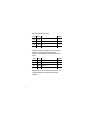
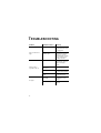
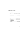
MC-X
user manual
©1999 Martin Professional A/S, Denmark.
All rights reserved. No part of this manual may be
reproduced, in any form or by any means, without
permission in writing from Martin Professional A/S,
Denmark.
Printed in Denmark.
P/N 35000081, Rev. A
INTRODUCTION
Thank you for selecting the Martin MC-X Controller.
The MC-X is a remote control for the Martin Exterior
600 and Exterior 600 Compact that allows the operator
to execute 7 programmable scenes, black out the light,
and engage stand-alone mode on all connected fixtures.
The seven scenes are programmed using a Martin
uploader such as the MPBB1.
SAFETY PRECAUTIONS
The MC-X is not for household use. For safe operation,
read this manual before use and follow the safety
precautions listed below. If you have questions about
how to operate the controller safely, please contact
your Martin distributor or dealer.
•
Disconnect the fixture from AC power when not in
use.
•
Ground (earth) the device electrically.
•
Refer all service to a qualified technician.
•
Do not expose the device to rain or moisture.
•
Do not open the device or remove any part; there are
no user-serviceable parts inside.
SETUP
UNPACKING
The MC-X comes with:
•
•
•
•
1.5-meter IEC power cable
5-meter 3-pin XLR data cable
3-pin male XLR termination plug
user manual
AC POWER CONNECTION
Warning!
For protection from electric shock, the
fixture must be grounded (earthed).
The AC mains supply shall have
overload and ground-fault protection.
The fixture’s mains lead must be fitted with a
grounding-type co rd cap th at fits your powe r
distribution cable or outlet. Consult an electrician if
you have any doubts about proper installation.
•
Following the cord cap manufacturer’s instructions,
connect the yellow and green wire to ground (earth),
the brown wire to live, and the blue wire to neutral.
The table shows some pin identification schemes.
4
Wire
Pin
Marking
Screw color
brown
live
“L”
yellow or brass
blue
neutral
“N”
silver
yellow/green
ground
green
DATA CONNECTION
A reliable data connection begins with the right cable.
Microphone cable cannot transmit DMX data reliably
over long runs. For best results, use only cable
designed for RS-485 applications. One cable for
connecting the first fixture is included; if need
additional cables your Martin dealer can supply them
in various lengths.
1
Connect a data cable to the controller’s DMX output.
Lead the cable from the MC-X to the first Exterior
600 and plug it into the fixture’s DMX input, which
has a male XLR plug.
2
Connect the DMX output of the first Exterior 600 to
the DMX input of the next Exterior 600. Continue
connecting fixtures output to input; up to 32 fixtures
may be connected on one data link.
3
Terminate the link by inserting the male termination
plug, included, into the DMX output of the last
fixture. A termination plug is an XLR connector with
a 120 ohm resistor soldered across pins 2 and 3.
5
FIXTURE SETTINGS
To receive commands from the MC-X, which sends
DMX control signals with a special start code, the
Exterior 600 must be in DMX mode 1 or 2 or have
automatic protocol detection enabled. The fixture may
be set to any DMX address.
Enable aut omati c protocol det ect ion
Automatic protocol detection must be enabled if the
fixtures have previously been set up in Martin mode for
operation with the Martin 3032 controller. If you do not
know the setup, go ahead and perform this procedure.
1
Connect the serial link or the DMX input of the
fixture to be programmed to the uploader’s DMX /
RS 485 output. Apply power to the fixture and the
uploader.
2
Turn on automatic protocol detection using the
uploader and following the steps below.
6
Press Times To
Display
up/
down
as
select fixture menu
needed
FIXT
Enter
1
enter fixture menu
dMX
down
1
select Martin mode
MART
Enter
1
enter submenu
ALL
Enter
1
enter submenu
PSET
down
as
select special menu
needed
SPEC
3
Press Times To
Display
Enter
1
enter special menu
dLoF
down
3
select automatic protocol
detection menu
AUTO
Enter
1
enter menu
OFF
up
1
select ON
ON
Enter
1
save selection
AUTO
Turn the fixtures off and on again to reset them.
7
OPERATION
PROGRAMMING SCENES
Starting with Exterior 600 software version 1.4, and
Exterior 600 Compact software version 1.0, seven
scenes - combinations of colors and effects - can be
programmed and stored in the Exterior’s electronic
memory.
These scenes are programmed using a Martin uploader
such as the MPBB1. Note that the uploader must be
loaded with the same software as the fixture; refer to
the fixture user manual for the upload procedure. (User
manuals are available online from the service and
support area of the Martin web site at
http://www.martin.dk.)
8
The following effects may be programmed.
Parameter
Menu
Options
Effect
Dimmer*
dIM
0- 255
Full open Æ full closed
Color filter*
COL
WH IT
Open
CT C
CTC filter
RE d
Red
GR EE
Green
BL UE
Blue
Cyan
CYAN
0- 255
White Æ Cyan
Magenta
MAG
0- 255
White Æ Magenta
Yellow
YEL
0- 255
White Æ Yellow
Frost*
FROS
ON
Frost on
OF F
Frost off
Zoom*
ZOOM
0- 255
Wide Æ narrow
Lamp
LAMP
ON
Lamp power on
OF F
Lamp power off
*Available on the Exterior 600 only.
9
Program scenes
•
Connect the serial link, or the DMX input of the
fixture to be programmed, to the uploader’s DMX /
RS 485 output. Apply power to the uploader first and
then the fixtures.
•
To program all connected fixtures, or to program a
single connected fixture at an unknown address,
follow the steps in the table below. If programming a
single fixture with this method, disconnect any
other identical fixtures from AC power and/or the
data link.
Press Times To
10
Display
Menu
as
go to top of menu (display stops varies
needed changing)
up/
down
as
select fixture menu
needed
FIXT
Enter
1
enter menu
dMX
Enter
1
enter menu
ALL
Enter
1
enter menu
PSET
•
To program a single fixture with a known DMX
address, use the following procedure. The uploader
user manual describes how to find an address.
Press Times To
•
Display
Menu
as
go to top of menu (display stops varies
needed changing)
up/
down
as
select fixture menu
needed
FIXT
Enter
1
enter menu
dMX
Enter
1
enter menu
ALL
down
1
select single fixture mode
SING
Enter
1
enter address selection menu
001
up/
down
as
scroll to the fixture’s DMX
needed address
varies
Enter
1
PSET
set uploader to fixture’s DMX
address
Select a scene to program.
Press Times To
Display
up/
down
as
select MC-X menu
needed
MC-X
Enter
1
PRE1
up/
down
as
select scene from 1 to 7
needed
varies
Enter
1
dIM
enter menu
enter effect menu
11
•
•
12
Program the dimmer level. (Exterior 600 only)
Press Times To
Display
up/
down
as
select dimmer level menu
needed
dIM
Enter
1
0
up/
down
as
adjust dimmer level
needed
0-255
Enter
1
dIM
enter menu
save setting and continue
Program the color wheel color. (Exterior 600 only)
Press Times To
Display
up/
down
as
select color wheel menu
needed
COL
Enter
1
enter menu
WHIT
up/
down
as
select color
needed
varies
Enter
1
COL
save setting and continue
•
•
Set CMY color.
Press Times To
Display
up/
down
as
select cyan menu
needed
CYAN
Enter
1
0
up/
down
as
set cyan level
needed
0-255
Enter
1
save setting and continue
CYAN
down
1
select magenta menu
MAG
Enter
1
enter menu
0
up/
down
as
set magenta level
needed
0-255
Enter
1
save setting and continue
MAG
down
1
select yellow menu
YEL
Enter
1
enter menu
0
up/
down
as
select yellow level
needed
0-255
Enter
1
YEL
enter menu
save setting and continue
Turn frost on/off. (Exterior 600 only)
Press Times To
Display
up/
down
as
select frost menu
needed
FROS
Enter
1
OFF
up/
down
as
turn frost on or off
needed
ON/OFF
Enter
1
FROS
enter menu
save setting and continue
13
•
•
Set zoom. (Exterior 600 only)
Press Times To
Display
up/
down
as
select zoom menu
needed
ZOOM
Enter
1
0
up/
down
as
select zoom level
needed
0-255
Enter
1
ZOOM
enter menu
save setting and continue
Program a lamp off command in one scene if you
want to control lamp power with the MC-X.
Otherwise, set the lamp command to ON in each
scene.
Press Times to
•
Display
down
1
select lamp menu
LAMP
Enter
1
enter menu
ON
up/
down
as
program lamp on or lamp off
needed command
ON/OFF
Enter
1
LAMP
save setting and continue
Repeat steps as necessary to program scenes 1 to
7. When finished, turn off and disconnect the
uploader.
14
EXECUTING SCENES
Once programmed, scenes may be executed using the
MC-X. Scenes have a 1-second fade-in time.
1
2
Set up the fixtures as described earlier.
Apply power to the MC-X and then to the Exteriors.
Allow the fixtures to reset.
3
To execute scenes, simply press and release the
buttons labelled “Preset 1” to “Preset 7.”
Executing any scene with a lamp on command will
cause the lamp to strike if the automatic lamp on
(ALON) feature is not enabled. After the lamp is on,
the lamp on command has no effect.
4
To black out the fixture(s), press and release the
button for the currently selected scene.
5
To engage stand-alone mode, press and release the
button labelled “Auto.”
Stand-alone mode is engaged with the programmed
clock and light settings. If the fixture is programmed to
operate from 8 to 11 pm and you press “Auto” at 7:30
pm, the fixture waits for 30 minutes before starting
stand-alone operation. Execute a scene to cancel standalone mode operation.
6
To turn off the lamp with the MC-X, execute the
scene (if any) prog ram med with the lamp off
command. Note: The lamp must cool for at least 8
minutes before it can restrike.
15
TROUBLESHOOTING
Problem
MC-X LEDs fail to
light.
Fixtures fail to
respond to MC-X.
Probable cause(s)
Remedy
No power.
Check that power is
switched on and cables
are plugged in.
Internal circuit
breaker open.
Disconnect the
controller for several
minutes to reset the
circuit breaker. Consult
service technician if
problem reoccurs.
Bad data connection.
Inspect data cables and
connections, repair or
replace damaged
cables.
The data link is not
connected.
Connect data link.
Missing termination.
Insert termination plug
in output of last fixture.
Fixtures set to Martin
mode.
Enable automatic
protocol detection.
No “lamp on”
command.
Program “lamp on”
commands in 6 or 7
scenes.
Defective lamp.
See fixture user
manual.
No light.
16
SPECIFICATIONS
PHYSICAL
•
•
Size ............................ 140 x 110 x 62 mm (5.5 x 4.3 x 2.4 in)
Weight................................................................... 0.5 kg (1lb)
CONTROL
•
•
•
•
•
Data output connection ...............................3-pin XLR, female
Pin-out ...................... pin 1 shield, pin 2 cold (-), pin 3 hot (+)
Control protocol....................................................... DMX-512
Start code ............................................................................ 223
Output channel........................................................................ 1
AC POWER
•
•
•
Input................................................. 3-prong IEC male socket
Maximum power and current............... see serial number label
Overload protection ..............................internal circuit breaker
CONSTRUCTION
•
•
•
Housing.................................................................... aluminum
Face plate .................................................. anodized aluminum
Protection factor .............................................................. IP 20
17
18
19
Martin Professional A/S
Olof Palmes Allé 18, 8200 Aarhus N, Denmark
Phone: +45 8740 0000, Fax: +45 8740 0010
URL: http://www.martin.dk