1
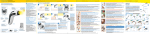
INTRABEAM Technical Specifications Content 1. System Description 4 2. Applications 6 3. Mobility of the System & Components 10 4. System Dimensions11 5. Miniaturized Accelerator12 6. Beam Characteristics13 7. Radiation Safety15 8. Quality Assurance and Dosimetry 16 9. Safety Concept (Interlock)18 10. Technical Requirements20 11. Processing (Cleaning, Disinfection, Sterilization) 2 21 3 1. System Description INTRABEAM® received FDA approval in the USA in 1997 and was awarded the CE certification in Europe in 1999 for the irradiation of targeted lesions using intersitial, intraoperative, intracavity or surface irradiation techniques. Treatment can be performed in operating rooms; structural alterations for radiation protection are normally not required. The miniaturized accelerator of INTRABEAM produces low-energy x-ray photons which are emitted isotropically (equally distributed). The INTRABEAM carrier system with six degrees of freedom, weight compensation and magnetic brakes ensures easy, flexible and precise positioning of the miniaturized accelerator into the targeted area. Ideally integrated in the INTRABEAM Cart, the control unit ensures exact setting and monitoring of the desired dose. INTRABEAM is a mobile system which is therefore suitable for use in multiple operating rooms. Miniaturized Accelerator The miniaturized accelerator emits low-energy X-ray photons (max. 50 kV) in an isotropic distribution for uniform dose delivery. Maneuverability Six axes allow the miniaturized accelerator to be placed anywhere in three dimensional space required for therapy. Applicators Multiple applicator types (see page 6 ff), which can be attached to the miniaturized accelerator, adapt the radiation field for a variety of applications. Floor Stand The Floor Stand combines performance with reliability, flexibility and ease of use: electromagnetic brakes lock the miniaturized accelerator in the treatment position with millimeter accuracy. Suitable for mobile use in any OR. 4 5 2. Applications The physical and radiobiological characteristics of the miniaturized accelerator‘s low-energy photons allow for use in a range of applications. This allows use within many body sites. A range of different applicators is available to meet the various clinical requirements. 2.1 INTRABEAM Spherical Applicator 2.2 INTRABEAM Needle Applicator 2.3 INTRABEAM Flat Applicator * The INTRABEAM Spherical Applicators are used for The INTRABEAM Needle Applicator can be used The INTRABEAM Flat Applicator is used for the the intracavitary or intraoperative delivery of radia- for the interstitial irradiation of tumors, e.g. in the treatment of tumors on surgically exposed surfaces, tion to the tumor bed, e.g. at the time of breast treatment of vertebral metastases. Spinal metas- e.g. tumors of the gastrointestinal tract. The conserving surgery. The applicator fills the tumor tases are often accompanied by severe pain and INTRABEAM Flat Applicator has an optimized flat cavity created by the tumor excision. The tumor the danger of a compression fracture. In Kypho- radiation field (by means of a flattening filter) at bed tissue adheres to the applicator via surface ten- IORT with INTRABEAM vertebral metastases can be 5 mm from the applicator surface. Using the Posi- sion. The probe tip is centered within the applicator irradiated intraoperatively in a targeted, localized tion Marker, a sterilizable metal ring which may be and therefore the tumor cavity. The INTRABEAM and minimally invasive technique using the needle placed on the surgically exposed surface, the area Spherical Applicators are available in the diameters applicator. After the intraoperative radiotherapy the to be irradiated can be isolated. The INTRABEAM 1.5, 2, 2.5, 3, 3.5, 4, 4.5, 5 cm. The applicators are affected vertebra is stabilized by the insertion of Flat Applicators are available in the diameters 1, 2, reusable and sterilizable. Please refer to the instruc- bone cement in a procedure known as kyphoplasty. 3, 4, 5 and 6 cm. The applicators are reusable and tion manual. The single use INTRABEAM Needle Applicator has sterilizable. Please refer to the instruction manual. a diameter of 4.4 mm. * This INTRABEAM applicator has CE certification and is awaiting FDA approval. As of April 2012. 6 7 2.4 INTRABEAM Surface Applicator * 2.5 INTRABEAM Cylinder V Applicator * The INTRABEAM Surface Applicator is used in the The INTRABEAM Cylinder V Applicator is used for treatment of tumors on the surface of the body, the irradiation of vaginal wall tumours and consists for example, irradiation of non-melanoma skin of a cylindrical applicator and a probe guard which cancers. It is particularly useful for patients with may be inserted in the applicator. The Dwell Step- high surgical risk or for the purposes of cosmesis. per allows the probe guard, which encases the The applicator creates an optimized flat radiation tip of the miniaturized accelerator, to be precisely field (by means of a flattening filter) on the target positioned in the INTRABEAM Cylinder V Applica- surface. Using the Position Marker, a sterilizable tor. This enables manual stepping of the probe tip metal ring which may be placed on the surface of and establishment of a homogeneous cylindrical the body, the area to be irradiated can be isolated. dose distribution of a user defined length. The The INTRABEAM Surface Applicator is available in INTRABEAM Cylinder V Applicator is available in diameters of 1, 2, 3 and 4 cm. The applicators are diameters of 2, 2.5, 3 and 3.5 cm. The applicators reusable and sterilizable. Please refer to the instruc- are reusable and sterilizable. Please refer to the tion manual. instruction manual. Component INTRABEAM Spherical Applicator INTRABEAM Needle Applicator INTRABEAM Flat Applicator INTRABEAM Surface Applicator INTRABEAM Cylinder V Applicator Available sizes 1.5 cm, 2.0 cm, 2.5 cm, 3.0 cm, 3.5 cm, 4.0 cm, 4.5 cm, 5.0 cm diameter 4.4 mm diameter 1.0 cm, 2.0 cm, 3.0 cm, 4.0 cm, 5.0 cm, 6.0 cm diameter 1.0 cm, 2.0 cm, 3.0 cm, 4.0 cm diameter 2.0 cm, 2.5 cm, 3.0 cm, 3.5 cm diameter Components of a set • INTRABEAM Sperical Applicator • Sterilization container • INTRABEAM Needle Applicator • Guide shaft (2x) • INTRABEAM Flat Applicator • INTRABEAM Position Marker • INTRABEAM Lumen Plug • INTRABEAM Surface Applicator • INTRABEAM Positionsmarker • INTRABEAM Lumen Plug • INTRABEAM Cylinder V Applicator • INTRABEAM Cylinder V Probe Guard • INTRABEAM Lumen Plug • INTRABEAM Cylinder V Dwell Stepper • INTRABEAM Cylinder V Base Plate Usage reusable single use reusable reusable reusable Anatomical Sites Any part of the human body (not intended for use on the heart or in the central circulatory system) Any part of the human body (not intended for use on the heart or in the central circulatory system) Any part of the human body (not intended for use on the heart or in the central circulatory system) Skin Vagina and surrounding tissue Geometry of dose distribution spherical dose distribution spherical dose distribution Flat dose distribution, optimized for tissue radiation in 5 mm distance from the applicator surface Flat dose distribution, optimized for tissue radiation directly in contact with the surface Cylinder-shaped dose distribution Guide shafts can be used for deep approach routes Fixation via INTRABEAM Position marker (can be sewed or glued to the region of interest) possible Fixation via INTRABEAM Position marker (can be sewed or glued to the region of interest) possible Fixation by use of INTRABEAM Cylinder V Base Plate Fixation to the region of interest Length [mm] Ø 1.5 cm: 167.5 mm (6.59“) Ø 2.0 cm: 170.0 mm (6.69“) Ø 2.5 cm: 172.5 mm (6.79“) Ø 3.0 cm: 175.0 mm (6.89“) Ø 3.5 cm: 177.5 mm (6.99“) Ø 4.0 cm: 180.0 mm (7.09“) Ø 4.5 cm: 182.5 mm (7.19“) Ø 5.0 cm: 185.0 mm (7.28“) 94 mm (Probe length) Ø 1.0 cm: 169.05 mm (6,67”) Ø 2.0 cm: 174.05 mm (6,85”) Ø 3.0 cm: 178.05 mm (7,01”) Ø 4.0 cm: 181.55 mm (7.15”) Ø 5.0 cm: 184.35 mm (7.26”) Ø 6.0 cm: 185.55 mm (7.31”) Ø 1.0 cm: 169.05 mm (6.67”) Ø 2.0 cm: 174.05 mm (6.85“) Ø 3.0 cm: 178.05 mm (7.01”) Ø 4.0 cm: 181.55 mm (7.15“) Ø 2.0 cm: 120.5 mm (47.4”) Ø 2.5 cm: 120.5 mm (47.4”) Ø 3.0 cm: 120.5 mm (47.4”) Ø 3.5 cm: 120.5 mm (47.4”) Inner diameter (absorption body) N/A N/A Ø 1 cm: 10 mm (0.39”) Ø 2 cm: 20 mm (0.79”) Ø 3 cm: 30 mm (1.18”) Ø 4 cm: 40 mm (1.57”) Ø 5 cm: 50 mm (1.97”) Ø 6 cm: 60 mm (2.36”) Ø 1 cm: 10 mm (0.39”) Ø 2 cm: 20 mm (0.79”) Ø 3 cm: 30 mm (1.18”) Ø 4 cm: 40 mm (1.57”) N/A Outer diameter Ø 1.5 cm: 15 mm (0.59“) Ø 2.0 cm: 20 mm (0.79“) Ø 2.5 cm: 25 mm (0.98“) Ø 3.0 cm: 30 mm (1.18“) Ø 3.5 cm: 35 mm (1.38“) Ø 4.0 cm: 40 mm (1.57“) Ø 4.5 cm: 45 mm (1.77“) Ø 5.0 cm: 50 mm (1.97“) Ø 4.4 mm Ø 1 cm: 14 mm (0.55”) Ø 2 cm: 24 mm (0.94”) Ø 3 cm: 34 mm (1.34”) Ø 4 cm: 44 mm (1.73”) Ø 5 cm: 54 mm (2.13”) Ø 6 cm: 64 mm (2.52”) Ø 1 cm: 14 mm (0.55”) Ø 2 cm: 24 mm (0.94”) Ø 3 cm: 34 mm (1.34”) Ø 4 cm: 44 mm (1.73”) Ø 2.0 cm: 20 mm (0.79”) Ø 2.5 cm: 25 mm (0.98”) Ø 3.0 cm: 30 mm (1.18”) Ø 3.5 cm: 35 mm (1.38”) Materials used for applicators and components • Stainless steel • ULTEM (Polyetherimide) • Stainless steel • ULTEM (Polyetherimide) • Polycarbonate • Stainless steel • ULTEM (Polyetherimide) • EPDM • Stainless steel • ULTEM (Polyetherimide) • EPDM • Stainless steel • ULTEM (Polyetherimide) • EPDM * This INTRABEAM applicator has CE certification and is awaiting FDA approval. As of April 2012. 8 9 3. M obility of the System & Components 4. System Dimensions The INTRABEAM system is highly mobile and all The cart and Floor Stand can be moved through components are easily transportable. Most com- standard width doors and within elevators. When in ponents, such as the 1.6 kg miniaturized accelera- use, the miniaturized accelerator is inserted in the tor, are stored in containers upon the INTRABEAM arm of the INTRABEAM carrier. The carrier can be Cart. The cart and floor stand can be easily stowed moved smoothly to any position in the OR due to its 29.13“ x 76.38“ x 59.06“ away with components when not in use. The cart‘s intergral casters located in the base. Weight com- (Width x height x length) spacious table top allows the system quality assur- pensation and six axes provide enough freedom to ance check to be carried out in situ. The touch key position the miniaturized accelerator within any posi- terminal, control console, dosimeter and all other tion in three dimensional space needed for access to components required for system quality assurance the treatment area. Electromagnetic brakes hold the INTRABEAM Bodenstativ and the treatment are mounted ergonomically on miniaturized accelerator in the exact position during INTRABEAM Control Unit the cart. Large casters and guiding rollers ensure treatment. The operator can monitor and controls easy transportation inside and outside the operat- the system at any time during the treatment from the ing room. The set up of the cart also ensures quick control panel on the INTRABEAM Cart. INTRABEAM Floor Stand INTRABEAM Cart Unloaden weight of cart: Weight: 275 kg / 606 lbs Transport position: 740 x 1940 x 1500 mm / 105 kg / 231 lbs (incl. permanently mounted user terminal) Payload max.: 95 kg / 209.43 lbs Dimensions: 900 x 1690 x 600 mm / 35.43“ x 66.53“ x 23.62“ (Width x height x length) Gerätedaten Miniaturized Accelerator: Weight: 4.5 kg / 9.92 lbs Dimensions: Maßbilder 381 x 305 x 89 mm / INTRABEAM X-ray Source XRS 4 Weight: 15.00“ x 12.01“ x 3.50“ and easy cleaning before entering the OR. 1.6 kg / 3.57 lbs Dimensions: 70 x 175 x 110 mm / (Width x height x length) 2.75“ x 6.89“ x 4.32“ 1 Arbeitsstellung (Width x height x length) 100-240 V AC 2 Transportstellung Rated voltage: Power consumption (max.): 60 VA 131 1 0300 INTRABEAM Bodenstativ 0mmm Hz Rated frequency: (51 50-60 m5.118. “ -11660000 8 40“ -μA Beam current at 40 kV: mmm m - 6622. ,9999“ “) 5, 10, 20 or 40 μA Beam current at 50 kV: Gerätedaten Maßbilder 1 Arbeitsstellung 2 2 Transport position 2 Transportstellung 1 Working position 1 1850 mm 131 0300 1800 mm 0mmm 1850 - 1800 mm (51 m-(72.83“ 72,83 -70,87“ 5.118. “ 11660000 70.87“) 8“ - 6 m m - 622. mm ,9999“ “) 151 05000 mmmm (-5599 .0,066 ““) ca. 1000 mm (ca. 39.37“) 1000 mm -39,37“ 2 1850 mm 1800 mm 1850 - 1800 mm (72.83“ 72,83 -70,87“70.87“) 151 05000 mmmm ca. 1000 mm (ca. 39.37“) 1000 mm -39,37“ 8585 0 0mm mm (3333 .4,466 ““) 1940 1940 mmmm -76,38“ 76.38“ (-5599 .0,066 ““) m mm 00m 7474 ““) .,13 9 9 2 2 -( 1940 1940 mmmm -76,38“ 10 11 76.38“ Version 5.0 G-30-1476-de Seite 79 5. Miniaturized Accelerator 6. Beam Characteristics The miniaturized accelerator of INTRABEAM accelerates electrons through the 100 mm drift tube with a maximum voltage of 50 kV onto a gold target where the low-energy photons are generated and then emitted isotropically. • P oint-source type x-ray emission Internal Radiation Monitor • S pherical dose distribution around the isocentre of the miniaturized accelerator (XRS 4) • Steep dose gradient (approx. 1/r3) in water (soft tissue equivalent) • Positional accuracy of delivered dose +/- 1 mm at 40 mm treatment diameter (from isocentre) Online dose monitoring An internal radiation monitor (IRM) detects the part of the x-ray photons emitted in the direction of the cathode Beam characteristics of the miniaturized Beam characteristics of the and records dose output in real-time.* The IRM result is accelerator (XRS 4) INTRABEAM Needle Applicator displayed on the treatment screen of the control terminal Spherical dose distribution of the emitted x-rays. so that the operator knows what dose is being delivered The steep dose gradient (due to rapid low kV x-ray at any time throughout treatment. attenuation) ensures a localized dose distribution. 40 kV / 40 μA * Subject to appropriate calibration. 50 kV / 5, 10, 20 or 40 μA Cathode Gun 30 30 1 Gy/min 2 Gy/min 3 Gy/min 4 Gy/min 20 5 Gy/min 6 Gy/min 7 Gy/min 149% 2% 20 123% 5% 100% 16% Height [mm] Accelerator Section 76% 10 10 mm 0 -10 -20 47% 117% 18% 80% 11% 39% -10 7% 4% 2% -20 Source Settings: 29% 100% 0 3% 50 kV, 40 µA -30 -30 Beam Deflector -20 -10 0 10 2% 20 -30 -30 30 mm 1% -20 -10 0 10 20 30 Width [mm] Percentage Depth Dose Curve: Normalized at 10 mm Electron Beam Gold Target Depth Dose Curve (%) 1000 100 10 1 0 5 10 15 20 25 30 35 40 45 Distance to XRS Isocentre (mm) 12 13 7. Radiation Safety Beam characteristics of the INTRABEAM Beam characteristics of the INTRABEAM Radiation measurement during clinical procedure. Measurements were taken at Flat Applicator, 5 cm diameter Surface Applicator, 4 cm diameter treatment delivery eight different angles relative to the isocenter of The INTRABEAM Flat Applicator has an optimized The INTRABEAM Surface Applicator creates To measure the radiation exposure a realistic an- the source at a radial distance of 1 and 2 m. The flat radiation field (by means of a flattening filter) an optimized flat radiation field (by means of a thropomorphic phantom with a silicone breast was measurements were then repeated at 1 and 2 m at 5 mm from the applicator surface. flattening filter) upon the target surface. created in which a 3.5 cm spherical applicator was above floor level. 50 kV / 5, 10, 20 or 40 μA 50 kV / 5, 10, 20 or 40 μA inserted. The irradiation area was covered with the INTRABEAM Radiation Shield, Flat as in a standard Experimental set-up for radiation exposure measurements with the phantom 1 m distance, 1 and 2 m height 2 m distance, 1 and 2 m height Radiation field in 0 mm depth 300% 20 30 300% 20 200% 200% 0 150% -10 100% -30 -30 -30 20 30 60% 50% 40% 95% 85% 30% 20% 10% 0% -30 -20 Width [mm] 30 70% -10 0% 10 90% 0 -20 0 90% 100% 50% -10 103% 100% 10 -20 -20 Radiation field in 0 mm depth 80% 250% 10 Height [mm] 350% Height [mm] 30 -10 0 10 20 30 Width [mm] Radiation field in 5 mm depth 20 350% 30 300% 20 Radiation field in 5 mm depth 103% 100% 90% 95% 200% 0 150% -10 100% 100% 10 Height [mm] 10 Height [mm] 80% 250% 70% 60% 0 50% 50% -30 -30 0% -20 -10 0 10 20 -30 -30 30 Width [mm] 50% 12 300% 10 200% 6 150% 95% 100% 107% 100% -10 0 10 20 50% 0% 0 10 Width [mm] 14 distance of 2 m would need to be maintained from appropriately with the flat INTRABEAM radiation the public area (e.g. the corridor) to ensure that the shield, 10 patients can be treated a year until an corresponding wall and/or window shields the ra- exposure dose of 1 mSv is reached at a distance of diation by a factor of at least 10. This corresponds 2 m from the x-ray source at a height of 1 meter. to a material with a lead equivalent of 0.05 mm at 103% 100% 90% 8 20% 6 20 30 a peak energy of 50 kV such as 10 mm of concrete 60% or 26 mm of gypsum. 40% 4 30% 20% 2 0,5 -30 70% 50% 10% 70% -10 If 100 procedures per year are to be performed, a protection other than covering the irradiation area Radiation field from 0.5 mm depth 200% -20 Without the use of any means of external radiation 30 50% 2 0,5 -30 Example 2: 80% Depth [mm] 8 Depth [mm] 350% 250% 4 Example 1: 10% Width [mm] Radiation field from 0.5 mm depth 10 20% 0% -20 level with INTRABEAM 30% -20 -20 12 40% 25% 20% -10 Examples to illustrate the exposure 80% -20 -10 0 10 Calculated based on values taken from US National Council on Radiation Protection and Measurements (NCRP), Structual Shielding Design for Medical X-Ray Imaging Facilities, Rep. 147, Bethesda, MD (2004) Detailed information are available in our brochure “Information on Radiation Safety“ 0% 20 30 Width [mm] 15 8. Quality Assurance and Dosimetry A full set of quality assurance and dosimetry tools is provided with the INTRABEAM. The factory-calibrated system is delivered with the specific depth dose curves and a reference measurement with the ion chamber integral to the system. Prior to every treatment, a twostep quality control check ensures that all parameters such as isotropy, internal radiation monitor and output work do not exceed the tolerances defined during calibration. For commissioning, a completely shielded, manually adjustable water phantom can be used to verify the depth dose curve. Online dose monitoring 8.2 Online control through IRM An internal radiation monitor (IRM) detects the part of the x-ray photons emitted in the direction of the cathode and records dose output in real-time.* On-site dose monitoring The IRM result is displayed on the treatment screen of the control terminal so that the operator knows what dose is being delivered at any time throughout treatment. * Subject to appropriate calibration. Verification of the Isotropie and the Dose output Independant verification of the Depth Dose Verification of the Isotropie and the Dose output Curve and the Dose distribution 8.1 QA Check (QA Tools) 8.3 Radiation protection during dosimetry Inside the so called PDA (Photo Diode Array), The three elements Every tool provided with the INTRABEAM for quality five diodes positioned orthogonally to each of quality assurance assurance is completely self shielded and does not other measure the radiation of the miniaturized with INTRABEAM require any additional radiation protection. accelerator. The objective of this test is to assure the isotropy (i.e. spherical pattern) of the emitted beam. With the PAICH (Probe Adjuster Ion Chamber 8.4 Commisioning Independant verification of the Depth Dose Curve and the Dose Distribution (System calibration by Carl Zeiss and with the water phantom) A water phantom with a high precision movement Holder) the output can be checked. An ion technique enables the physicist to position the tip of chamber is mounted onto the probe adjuster in the miniaturized accelerator exactly above or beside such a way that the ion chamber window sits right the ion chambers inside the water. Accurate above the tip of the miniaturized accelerator. In positioning and stepping of the source ensures the this test, the internal radiation monitor is verified as verification of the depth dose curve. Even the well. The counts measured by the internal radiation measurement of a depth dose curve is possible. monitor are compared with the reading of the ionization chamber. The miniaturized accelerator is not enabled for treatment planning until a coefficient has been computed. Temperature and pressure sensors are located within the control unit and the PAICH. Pressure and temperature can be calibrated to ensure exact dose calculation. 16 17 9. Safety Concept (Interlock) A monitoring system checks the INTRABEAM during • T he user is requested via the user interface to 9.2 Interlock to prevent unintended access 9.4 Interlock to prevent incorrect dose entry • T he dose to be administered must only be pre- the treatment and quality assurance. It prevents the press the start button at least twice to confirm to the controlled area user against unintended radiation emissions and that he really wants to perform the test. The •R adiation emission is acoustically and visually optional unintended access to the controlled area unintended execution of a verification test is not indicated on the miniaturized accelerator and the doctor (this is a legal requirement in most coun- and incorrect radiation data transmission (see 9.1 possible. user interface. Persons entering the controlled tries; information during system training and note scribed by an appropriately trained, authorized – 9.3). This safety concept is also responsible for • T he optical interlock enables the system to detect ensuring the proper control during treatment and if the miniaturized accelerator has been correctly In case of an interference a sound alert is triggered. mounted on the INTRABEAM Floor Stand. The To obtain the license for the utilization of the system also detects whether the applicator has external warning lamp or a door contact switch doctor (this is checked via the profile of the user INTRABEAM, it may require creation of a safety been attached correctly. The miniaturized accel- can be connected with the INTRABEAM via an name), must verify the dose planning and confirm plan and/or failure analysis, a hospital radiation erator will only be enabled for radiation emission external interlock switch. If, for example, the it by entering a password. protection manual and an emergency plan. if it has been correctly mounted on the carrier external interlock is activated by opening of the system intended for it. door during a treatment session, radiation emis- 9.5 Interlock to prevent interference with the sion is instantly interrupted automatically and application software Suggestions on how to establish this can be provided by Carl Zeiss. •O nce the miniaturized accelerator has been suc- area are able to obtain information on the radiation status of the system. • In addition, further safety systems such as an in the user manual). • T he dose is entered by one person (usually a physicist), and a second person, who must be a cessfully connected to the carrier system, the user can only be resumed after the interlock has been • T he INTRABEAM is a closed system. Only data 9.1 Interlock to prevent unintended must follow the menu prompts on the user inter- closed and continued radiation emission has been conforming to the specific data format of the radiation emission face to actively set the system status to ready for confirmed. application software can be loaded via CD/DVD. Unintended radiation emissions are prevented radiation emission. Radiation will only be emitted by an optical interlock system and a multilayered inquiry in the software: if the user presses the Start button again. •A s soon as the system is ready for radiation emis- 9.3 Interlock to prevent incorrect radiation data transmission sion, this ready status is indicated by an acoustic • E very signal transmitted by the control console to propriate verification device has been correctly signal. This warns the user that radiation will be the x-ray source is returned by the x-ray source attached to the miniaturized accelerator. Only emitted when the Start button is pressed again. and checked for completeness and correctness by • T he optical interlock detects whether the ap- then and only when the device protects the •R adiation emission can only be started by trained environment from radiation, will the miniaturized and authorized staff after the necessary verifica- accelerator be enabled for radiation emission. tion steps have been completed, the dose has If the device is removed during the test, radia- been verified by a password and the system has tion emission is immediately deactivated by the been set to the treatment mode. interlock. the control console. If the signal is not correctly returned by the miniaturized accelerator, radiation emission is stopped or not started. • T he count rate is constantly monitored during treatment by the internal radiation monitor. If the count rate deviates from the planned rate by more than 10%, radiation emission is stopped. • T he ratio between the planned treatment time and the count rate is constantly monitored. In the event of any deviations, radiation emission is stopped. 18 19 10. Technical Requirements 11. Processing (Cleaning, Disinfection, Sterilization) 10.1 Electrical requirements Two electrical outlets are necessary in order to operate the INTRABEAM All non-sterile components of the INTRABEAM can cleaning of the cart. The Floor Stand can also be be easily cleaned and disinfected. Large casters and cleaned in a very short time. nearly no tight cleavings ensure simple and quick during treatment – one for the Floor Stand and one for all components on the cart which are connected together with a medical insulating transformer. Component INTRABEAM Floor Stand INTRABEAM Cart Medical Insulating Transformer 100 V / 115 V / 230 V 115 V / 230 V 50 - 60 Hz 50 / 60 Hz Power consumption max. 400 VA 600 VA Electrical standard IEC 60601-1; CAN/CSA-C22.2 No. 601.1-M90 IEC 60601-1 / UL 60601-1; CAN/CSA-C22.2 No. 601.1-M90 Type B Type B Case protection IP20 IP20 Protection class Protection class I Protection class I Rated voltage Rated frequenzy Product classification Cleaning Disinfection Single Use/ Sterilizable Floor Stand c b – Cart c b – Control Console PRS 500 c a – User Terminal c b – Keyboard c a – Miniaturized Accelerator XRS 4 c a – Quality Tools (PDA/PAICH) c a – Cables (XRS/QA) c a – V-/X- Block c a – INTRABEAM Water Phantom d – – Transportation Trays (XRS 4 / QA) c a – INTRABEAM Spherical Applicator See user manual X Sterilizable with steam – – single use - sterile INTRABEAM Needle Applicator INTRABEAM Flat Applicator See user manual X Sterilizable with steam INTRABEAM Surface Applicator See user manual X Sterilizable with steam 10.2 Ambient requirements* INTRABEAM Cylinder V Applicator See user manual X Sterilizable with steam INTRABEAM Flat Shields – – single use - sterile Operation: INTRABEAM Drapes – – single use - sterile Temperature: +15 °C … +40 °C / 59 °F ... 104 °F Relative humdity: 30% … 75% Air pressure: 800hPa … 1060 hPa a = 4-7 % Hypochlorid, b = Meliseltol, c = wipe moist, d = ethyl alcohol, distilled water (1:1) plus a dash of household dish-washing liquid also mentioned in the detailled user manuals Transportation and Storage: Temperature: -20 °C … +70 °C / -4 °F ... 158 °F Relative humdity: 10% … 90% (without condensation) Air pressure: 500 hPa … 1060 hPa * Requirements could differ for accessories. Please see separate user manuals. 20 21 Cleaning, Disinfection and Sterilization of Applicators The processing of the applicators was validated Only use the steam sterilization method (fractioned by Carl Zeiss using the following procedure and vacuum method) described in this manual for ster- can therefore be processed in a sterile manner: ilization of the cleaned and disinfected applicators. Other procedures are not approved. If possible, clean and disinfect the applicators by machine. Expose the applicators and sterile containers only to temperatures no higher than 141°C (286 °F). Use the following materials for cleaning/ disinfection: • F iltered air for the drying process For steam sterilization, please take the following factors into account: • The steam sterilization method is validated according to DIN EN ISO 17665-1 • The maximum sterilization temperature is 138 °C (280 °F; plus tolerance according to DIN EN ISO 17665-1 • S oft brush •W ith the fractioned vacuum method, the steriliza- • S oft cloth tion time (exposure time at sterilization tempera- For the Cylinder V Applicator: •B rush the inside of the Cylinder V Applicators and if necessary of the probe guard •D isposable syringe (min. 10 ml) with attached long canulae ture) is at least 5 min at 132°C (270 °F)/ 134 °C (273 °F) or for the INTRABEAM Spherical Applicator 18 min (prion inactivation) Please see the user manual for detailed information on cleaning, disinfection and sterilization of the applicators. For Flat, Surface, Cylinder V Applicator: •U se the provided Lumen Plug Cleaning disinfecting agent: • T he disinfecting agent must be compatible with the cleaning agent used. • T he disinfecting agent must be suitable for the cleaning and disinfection of instruments made of metal and plastics. •R insing with sterile or low-germ (maximum 10 microbes/ml) and lowendotoxin (maximum 0.25 endotoxin units/ml) water (e.g. purified water/ highly purified water) The disinfecting agent must not contain the following: •O rganic, mineral and oxidizing acids (minimum permissible pH value: 5.5) • Strong bases (maximum permissible pH value: 8.5, recommended: neutral, enzymatic cleaning agent) •O rganic solvents (e.g. alcohol, ether, ketone, benzine) • Oxidants (e.g. hydrogen peroxide) • Halogens (chlorine, iodine, bromine) • Aromatic/halogenated hydrocarbons 22 23 Argentina Carl Zeiss Argentina S.A. Calle Nahuel Huapi 4015 / 25 C1430 BCO Buenos Aires Argentina Phone: +54 11 45 45 66 61 [email protected] Australia Carl Zeiss Pty Ltd Tenancy Office 4, Level 1 40-52 Talavera Road North Ryde NSW 2113 Australia Phone: +61 2 9020 1333 [email protected] Austria Carl Zeiss GmbH Laxenburger Str. 2 1100 Vienna Austria Phone: +43 1 79 51 80 [email protected] Belgium Carl Zeiss NV-SA Ikaroslaan 49 1930 Zaventem Belgium Phone: + 32 2 719 39 11 [email protected] Brazil Carl Zeiss do Brasil Ltda. Av. Naçoes Unidas, 21711 CEP04795-100 São Paulo Brazil Phone: +55 11 5693 5521 [email protected] Canada Carl Zeiss Canada Ltd. 45 Valleybrook Drive Toronto, ON M3B 2S6 Canada Phone: +1 800 387 8037 [email protected] China Carl Zeiss Shanghai Co. Ltd. 1/f., Ke Yuan Building 11 Ri Yin Nan Road Waigaoqiao Free Trade Zone 2005 Yang Gao Bei Road Shanghai 200131 China Phone: +86 21 5048 17 17 [email protected] Czech Republic Carl Zeiss spol. s.r.o. Radlická 14/3201 150 00 Prague 5 Czech Republic Phone: +420 233 101 221 [email protected] France Carl Zeiss Meditec France SAS 60, route de Sartrouville 78230 Le Pecq France Phone: +33 1 34 80 21 00 [email protected] Germany Carl Zeiss Meditec VG mbH Carl-Zeiss-Strasse 22 73447 Oberkochen Germany Phone: +49 7364 20 6000 [email protected] Surgical Ophthalmology: Phone: +49 800 470 50 30 [email protected] Hong Kong Carl Zeiss Far East Co. Ltd. Units 11-12. 25/F Tower 2, Ever Gain Plaza No. 88 Container Port Road Kwai Chung Hong Kong Phone: +852 2332 0402 [email protected] India Carl Zeiss India Pvt. Ltd. 22. Kensington Road Ulsoor Bangalore 560 008 India Phone: +91 80 2557 88 88 [email protected] Italy Carl Zeiss S.p.A. Viale delle Industrie 20 20020 Arese (Milan) Italy Phone: +39 02 93773 1 [email protected] Japan Carl Zeiss Meditec Japan Co. Ltd. Shinjuku Ku Tokyo 160-0003 22 Honchio-Cho Japan Ophthalmic instruments: Phone: +81 3 33 55 0331 [email protected] Surgical instruments: Phone: +81 3 33 55 0341 [email protected] 0297 Carl Zeiss Meditec AG Goeschwitzer Strasse 51–52 07745 Jena Germany www.meditec.zeiss.com/radiotherapy Email: [email protected] Malaysia Carl Zeiss Sdn Bhd. Lot2, Jalan 243/51 A 46100 Petaling Jaya Selangor Darul Ehsan Malaysia Phone: +60 3 7877 50 58 [email protected] Mexico Carl Zeiss de México S.A. de C.V. Avenida Miguel Angel de Quevedo 496 04010 Mexico City Mexico Phone: +52 55 59 99 0200 [email protected] Netherlands Carl Zeiss B.V. Trapezium 300 Postbus 310 3364 DL Sliedrecht Netherlands Phone: +31 184 43 34 00 [email protected] New Zealand Carl Zeiss (N.Z.) Ltd. 15B Paramount Drive P.O. Box 121 - 1001 Henderson, Auckland 0650 New Zealand Phone: +64 9 838 5626 [email protected] Poland Carl Zeiss sp. Z o.o. ul. Lopuszanska 32 02-220 Warsaw Poland Phone: +48 22 858 2343 [email protected] Singapore Carl Zeiss Ptd. Ltd. 50 Kaki Bukit Place Singapore 415926 Singapore Phone: +65 6741 9600 [email protected] South Africa Carl Zeiss (Pty.) Ltd. 363 Oak Avenue Ferndale Randburg 2194 South Africa Phone: +27 11 886 9510 [email protected] South Korea Carl Zeiss Co. Ltd. Seoul 121-828 Mapo-gu 141-1, Sangsu-dong 2F, BR Elitel Bldg. South Korea Phone: +82 2 3140 2600 [email protected] Spain Carl Zeiss Meditec Iberia S.A.U. Ronda de Poniente, 15 Tres Cantos 28760 Madrid Spain Phone: +34 91 203 37 00 [email protected] Sweden Carl Zeiss AB Tegeluddsvaegen 76 10254 Stockholm Sweden Phone: +46 84 59 25 00 [email protected] Switzerland Carl Zeiss AG Feldbachstrasse 81 8714 Feldbach Switzerland Phone: +41 55 254 7534 [email protected] Thailand Carl Zeiss Thailand Floor 8, Thosapol Land Building 2 230 Ratchadapisek Road Huaykwang, Bangkok 10310 Thailand Phone: +66 2 2 74 06 43 [email protected] United Kingdom Carl Zeiss Ltd. 15-20 Woodfield Road Welwyn Garden City Hertfordshire, AL7 1JQ United Kingdom Phone: +44 1707 871200 [email protected] United States of America Carl Zeiss Meditec, Inc. 5160 Hacienda Drive Dublin, CA 94568 USA Phone: +1 925 557 4100 [email protected] EN_30_010_0158II Printed in Germany AW-CZ-V/2012 Koo The contents of the brochure may differ from the current status of approval of the product in your country. Please contact our regional representative for more information. Subject to change in design and scope of delivery and as a result of ongoing technical development. Printed on elemental chlorine-free bleached paper. © 2012 by Carl Zeiss Meditec AG. All copyrights reserved. INTRABEAM® is a registered trademark of Carl Zeiss. Your local contact: