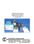
1
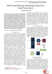
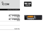
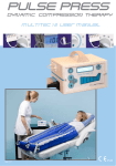
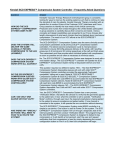
User Manual
Intermittent Pneumatic
Compression System
To ensure safe use of
this device, it is essential
that you read and fully
understand the information
contained within this
manual.
0473
Caution: Federal (USA) and European Union
law restricts this device to sale, distribution and
use by or on the order of a physician.
Mechanical
prophylaxis for the
prevention of Deep
Vein Thrombosis
1. Introduction
1.1 OVERVIEW OF THE SYSTEM
Thank you for choosing PneumaPress® DVT-2600. The product is a pneumatic
compression system which is used to improve the blood circulation for patients with
reduced mobility, therefore reducing the risk of DVT/VTE formation.
The product range comprises of a pump, connecting tubing and disposable cuff(s).
The pump has digital sensors to check the cuff connections, output and power supply.
If an error code shows during the initial operation, check the error code sticker on top
of the controller and action as advised.
This user manual contains information on how to use and maintain PneumaPress®.
Please read this manual to ensure you use this product correctly.
2. Clinical Information
2.1 Range of application and Effect of use
Air from the pump is delivered to the cuff(s) via 3 air chambers in the thigh, calf and
boot styles. The air will sequentially pressurise the chambers from 1st to 3rd. This
applies pressure to the legs and the veins within them, forcing blood up towards the
heart.
Please use this product as prescribed by medical staff and as per your Hospital/Trust
DVT/VTE policy and only once you have undertaken training in its use.
2.2 Contra-indications
PneumaPress® DVT-2600 system is not recommended for use with the
following conditions:
• Pre-existing deep vein thrombosis, phlebothrombosis or pulmonary embolism.
•
Presumptive evidence of congestive heart failure.
•
Inflammatory phlebitis process.
•
Severe arteriosclerosis or other ischemic vascular disease.
•
Decompensated cardiac insufficiency.
•
Carcinoma metastasis in the affected extremity.
•
Where lymphatic return is undesirable.
•
Severe arteriosclerosis or active infection.
2
2.3 PRECautions
•
•
•
•
•
If any pain or oedema occurs during use of the device, cease therapy and seek medical advice.
Use with caution on patients with recently fitted prosthesis.
Assess skin integrity frequently during use in patients with diabetes or vascular disease.
In the unlikely event of electric shock whilst using the device, remove device from power source and disconnect unit from patient.
Manual settings should be adjusted under the advice of a medical practitioner.
2.4 WARNINGS
•
•
•
Manual settings should be adjusted under the advice of a medical practitioner.
Do not attempt to repair a faulty device or replace broken tubing connectors as abnormal inflation of the cuff may occur. Contact your local representative.
Use the device with a suitable AC power cord observing the electronic standards for each local region. (Fire and electric shock are possible).
2.5 Clause 5
•
•
•
•
•
Type of protection against electric shock: Class 1 Equipment.
Degree of protection against electric shock: Not classified - BF applied parts.
Classify according to the degree of protection against ingress of water: IPXO, ordinary equipment.
This equipment is not suitable for use in the presence of flammable anaesthetics or oxygen.
Mode of operation - continuous operation.
2.6 Information regarding potential Electromagnetic or other Interference
This equipment has been tested and found to comply with the limits for medical
devices in EC/EN 60601-1-2. These limits are designed to provide reasonable protection
against harmful interference in a typical medical installation.
This equipment generates, uses and can radiate radio frequency energy and if not
installed and used in accordance with the instructions, may cause harmful interference
to other devices in the vicinity. However, there is no guarantee that interference will
not occur in a particular installation.
3
If this equipment does cause interference to other devices, which can be determined
by turning the equipment off and on. The user is encouraged to try to correct the
interference by one or more of the following measures:
•
•
•
•
Reorient or relocate the receiving device.
Increase the separation between the equipment.
Connect the equipment into an outlet on a different circuit.
Consult the manufacturer or technician for help.
2.7 WEEE Marking
This marking shown on the product or its literature, indicates that it should not be
disposed of with other household waste at the end of its working life. To prevent
possible harm to the environment or human health from uncontrolled waste disposal,
please separate this from other types of waste and recycle it responsibly to promote
the sustainable reuse of material resources.
Business users should contact their supplier and check the items and conditions of the
purchase contract. This product should not be mixed with other commercial waste for
disposal.
3. Product Description
3.1 Summary and Specifications
Composition
•
The pump.
•
Air connecting hose (tubing).
•
AC cable (plug).
•Cuff(s).
Specification
•
•
•
•
•
•
•
•
•
4
Model: DVT - 2600.
Weight: 2 Kg (only body).
Dimension: 190(W) x 200(D) x 162(H)mm.
Power consumption: 35 VA.
Fuse: Apply inside the AC inlet socket: F 3.15AL 250V.
Place: Indoors.
Ambient temperature & humidity: 0˚C~ 40˚C / below 60%.
Power source: AC 100V - 240V, 50/60Hz.
The information label sticker of DVT-2600 is attached on the rear of a controller.
Operating Principle
The pump will deliver air to the cuff(s) and sequentially pressurise them. Cuff(s) with 3 air
chambers will be pressurised from the 1st chamber (nearest to the foot) to the 3rd chamber.
Once the chambers are pressurised, the pump will provide an interval period for vein refilling
before the pump starts to pressurise the chambers again.
These cycles will be repeated throughout the time the unit is in use.
Intended Use
This product is a medical device to help reduce the risk of DVT/VTE formation by increasing
the flow of blood in the venous circulation from the legs back to the heart.
Please use this product under the guidance of medical staff and in line with your hospital(s)
DVT/VTE policy.
System features
•
The Self-Test Function:
On start up, the pump initiates an automatic check of the cuff connection and the type of cuff applied. The controller also detects any abnormal pressures encountered
during regular operation.
•
Manual Setting Program:
The pump is designed to allow custom pressure values to be delivered to
the patient.
5
3.2 THE functions
6 LCD
Control Buttons
Leg
pressure
3 button
display
Mode
2 button
Interval
5 button
4 Foot pressure
button
1 START/STOP
button
1. START/STOP: This button is used to start or stop the compression cycles. If an
error occurs, the pump automatically stops. To restart cycles press once.
2. MODE: In the UK, PneumaPress® is only marketed to provide ‘DVT/VTE prophylaxis’.
The mode button does not have a use - use in DVT mode only.
3. LEG PRESSURE: This button is used to set the required pressure to be delivered
to leg cuff(s). When the START/STOP button is pressed, the basic leg pressure will
automatically be shown (LEG/CALF/BOOT CUFF: 40mmHg).
It is not possible to change these settings whilst the pump is in operation.
6
The basic pressure is set as 40 mmHg and the pressure setting will be changed by
10mmHg with each depression of the button (eg.40g50g60g20g30g40mmHg).
The LCD screen will remain turned off if the user does not apply the cuff, as the
controller automatically selects the cuff when the START/STOP button is selected.
The pump has an automatic gradient pressure application that is applied into each
chamber of a cuff sequentially (+/-5 mmHG).
For cuff(s) with three chambers such as leg/calf/boot; if 40mmHG is set, pressure will be
delivered as 35/40/45mmHG to the three chambers.
4. FOOT PRESSURE: This button is used to set the required pressure to be delivered
to a foot cuff. When the START/STOP button is pressed, the basic foot pressure will
automatically be shown (FOOT CUFF: 120mmHg).
It is not possible to change these settings whilst the pump is in operation. The basic
pressure is set as 120mmHg and the pressure setting will be changed by 10mmHg with
each depression of the button (ex.120g130g140g120mmHg).
The LCD screen will switch off if the user does not apply a cuff, because the pump
selects the cuff automatically when START/STOP is pressed.
5. INTERVAL: This button is used to set the interval (cycle) time.
When the START/STOP button is pressed, the default setting of 48 sec is shown and can
be changed with each depression of the button: 60g28g48g60 sec.
Upon completion of pressurisation to each chamber, the pump has an interval period
to allow time for the vein to refill with blood, before the pump restarts to pressurise
the chambers again. These cycles will be repeated during the operating time set or until
discontinued.
It is not possible to change these settings whilst the pump is in operation.
7
6. LCD display screen:
A) Battery status indicator
PneumaPress® DVT-2600 is equipped with a back up battery pack.
An LED indicator is used to represent the charge status of the battery
(as per diagram below).
B) AC power indicator
AC power indicator (LED) is used to show mains power is attached and in use. If not
shown please check status of mains supply.
C) Battery charging indicator
Indicates whether batteries are charging. Indication of the battery charge level will not
be displayed when the unit is off. The indicator for battery charging will be displayed
only when the batteries are not fully charged.

The batteries require PneumaPress® to be switched on for charging. Warranty period
for the batteries will be 6 months after the date of purchasing.
D) Battery charging
To charge the batteries, please ensure PneumaPress® is plugged in and the power
switch is on. The amount of power the batteries can deliver will vary according to a
battery’s condition and the settings of the device. Regular battery charging time is
approximately 4 hours. Maximum running time is up to 8 hours.
E) Operation indicator
This LED indicator shows the status and type of cuff(s) applied, following the self test
application. It also shows if one or two legs are being compressed and to which leg
different cuff(s) are being used (i.e. leg and foot).
A moving LED shows pump in operation following self check application.
8
The operation indicator below displays the variety of cuff types which may be used.
Please note if there is no cuff applied to the pump, an error code will be displayed.
Operating Mode
The pump is able to provide two levels of therapy. For the UK, PneumaPress® is only
marketed to provide DVT/VTE prophylaxis.
Diagram 1
1. DVT OPERATING MODE: In DVT
mode, the pump pressurises the
cuff(s), (see diagram 1). If different cuff(s)
have been selected, pressure is applied
to foot cuff first, then the leg cuff(s).
Interval time will start after both
legs/cuff(s) have been pressurised.
Foot cuffs
Leg cuffs
2. Error Description: If there is an error with the pump; the error mode will start
with an alarm. The pump will stop and return to a waiting mode. Once the error is
corrected the pump will restart when the user presses START/STOP.
9
Error Mode
Vent error
Pressure in cuff
doesn’t ventilate.
No cuff(s) connected
to the pump.
Pump error
Device error
Low pressure error
AC cord (plug) error
30% under pressure
following 5
consecutive checks.
Power problem when
using AC power.
High pressure error
Battery power error
30% over pressure
following 5
consecutive checks.
Power problem when
AC power off and using
battery.
1. Code 10 (Cuff connection error): During power on,
the pump performs an automatic one cycle calibration
to detect cuff type(s) being used and confirm they are fitted
to the limb(s). If the pump fails to detect the cuff(s) error
code 10 will be displayed with an alarm sound.
1
2
Check the pump and cuff(s) to ensure the tubing is correctly fitted.
Check that each cuff is fitted correctly on the patient’s leg.
2. Code 21 (Low pressure error): If pressures lower than
30% of the set value are detected more than 5 times during
operation, error code 21 will be displayed.
1
2
3
4
Check the pump and cuff(s) to ensure the tubing
is correctly fitted.
Check that each cuff is fitted correctly on the patient’s leg.
Check whether there is any leakage from a connected cuff.
Disconnect the cuff and tubing, check air is being pumped from the air outlets on the pump.
3. Code 22 (High pressure error): If pressures higher than 30% of the set value are
detected more than 5 times during operation, error code 22 will be displayed.
10
1
2
3
Check whether the tubing is bent.
Check if there is something blocking the tubing.
Check the pump air output sockets for blockages.
4. Code 31 (Ventilation error): If air has not ventilated (deflated) under 20mm Hg
during the INTERVAL TIME, error code 31 will be displayed.
1
Check the inner solenoid valve (Exchange the valve).
5. Code 32 (Pump error): During the initial self detection test, if the pump is not
operating normally, error code 32 will be displayed.
1
2
Check pump operation after opening cover of the pump.
Check the wire connection in the pump.
6. Code 33 (System error): This error indicates serious damage to the inner pump.
Please call your local representative.
7. Code 41 (Power supply error): Code 41 is displayed if the power supply from the
outer AC is causing a problem. Please call your local representative.
8. Code 42: Code 42 is displayed when there is a problem with the power supply
generated by the inner batteries. Please call your local representative.
3.3 SYSTEM DESCRIPTION
Main Compositions
1. PneumaPress® DVT-2600 PUMP:
•
•
•
•
Voltage and AC power: AC 100 ~ 240V, 50/60Hz.
Power consumption: 25W(35VA).
Output: 2.
Pressure range: LEG 20 ~ 60mmHg, FOOT 120 ~ 140mmHg.
11
2. PneumaPress® DVT-2600 Accessories:
THIGH
CALF
FOOT
BOOT
TUBING
PRODUCT
CODE
SIZE
DS011
Small
DS012
Med
LENGTH OF
CALF SECTION
CALF
CIRCUMFERENCE
THIGH
CIRCUMFERENCE
NHS
CODES
53cm
31cm
26 - 40cm
50 - 76cm
EGD 7614
61cm
63.5cm
37 - 51cm
53 - 81cm
EGD 7615
DS013
Large
65cm
38.5cm
45 - 66cm
56 - 87cm
EGD 7616
DS014
X-Large
65cm
38.5cm
45-84cm
56-102cm
EGD 7617
PRODUCT
CODE
SIZE
LENGTH OF
CUFF
CALF
CIRCUMFERENCE
NHS
CODES
DS021
Small
28cm
19 - 36cm
EGD 7618
DS022
Med
33cm
29 - 46cm
EGD 7619
DS023
Large
35cm
35 - 56cm
EGD 7620
DS024
X-Large
35cm
Up to 97cm
EGD 7621
PRODUCT
CODE
SIZE
FOOT
CIRCUMFERENCE
NHS
CODES
DS031
One
size
fits
all
Up to 36cm
EGD 7622
PRODUCT
CODE
SIZE
LENGTH OF
CALF SECTION
CALF
CIRCUMFERENCE
FOOT
CIRCUMFERENCE
NHS
CODES
DS041
One
size
fits
all
33cm
27 - 46cm
Up to 28cm
EGD 7623
NHS
CODES
EGD
7635
PUMP
LENGTH OF
CUFF
Cuff usage and caution
TWO CUFFs & PUMP:
PRODUCT
CODE
DVT
-2600
ONE CUFF & PUMP:
12
3. Cuff usage and caution
•
•
•
Do not turn on the power switch before applying cuff(s) to a patient. Connect the tubing/hose after the cuff(s) are applied to the patient. Turn the power on after
connecting the hose(s) to the air socket at rear of PneumaPress® to ensure self check.
Do not operate with patient standing or sitting down. There could be a risk of
malfunction of PneumaPress® and cuff(s).
The manufacturer recommends using basic pressure settings for initial use.
Caution is recommended when using manual pressure settings. (Leg: over 50mmHG, Foot: over 140mmHg).
3.4 Controller Views
3.5 TECHNICAL DATA
Specifications and Dimensions
TEST DESCRIPTIONS
STANDARD
AC voltage
100-240V~, 50/60Hz
Power consumption
25W(38VA)
Air power consumption
Below 5W
Noise level
Above 2KV
Operation noise level
Below 60dB
Max. pressure level
140mmHg
Pump weight
2kg
Pump size
200(W) x 165(D) x 190(H) mm
3.6 PRODUCTS LABEL
1. Copyright
13
2. LABEL
Caution
BF Type Medical Equipment
Europe Certification Mark
Manufacturer Mark
Serial Number
Date of Manufacture
LOT Number
Service Supplier Mark
4. Product Composition
4.1 Package
PneumaPress® DVT-2600 box consists of the following:
•PneumaPress® DVT-2600.
•
Air connecting hose (tubing).
•
AC cable (plug).
•
Operations manual.
.
Cuff(s) are ordered separately and can be ordered in various sizes.
4.2 INSPECTION OF BOX
•
•
•
Caution: Do not open boxes by using sharp implements.
Ensure content matches above list.
Check power cable is correct for your locality and use.
4.3 Products or packaging defects
Please contact your representative if products are found to be damaged or items are
missing from the packaging.
4.4 PLEASE NOTE
1
Damage caused by the user during the opening of the packaging is not covered by the warranty. Please take care.
2
Please ensure PneumaPress® is stored safely, away from dust and humidity after
each use.
3
Ensure PneumaPress® is unplugged from the mains supply when not in use or being charged.
14
4.5 Environmental conditions for transport and storage
Operating
Condition
Temperature (˚C)
0-40
Relative humidity (%)
10-90
Atmospheric pressure (hPa)
Temperature (˚C)
Transport and Storage
Condition
Relative humidity (%)
Atmospheric pressure (hPa)
700-1060
-20-60
0-90
500-1060
5. Product Use Procedure
5.1 Before using this device
Only use PneumaPress® under the direction of medical staff and as per your hospital’s DVT/
VTE policy. Do not operate this device unless you have been trained to do so.
5.2 Setting up and using the device
1
2
3
4
5
6
7
8
Place the PneumaPress® on a hard, flat surface or hang using the bed hanger.
Connect to a suitable power supply.
Ensure the cuffs are the correct size and securely fitted to the patient.
Connect the applied cuff(s) to pump using connecting hose(s).
Turn on the power switch at the rear of the pump.
The pump will automatically self-test checking the cuff(s) attached.
Operate the pump by pressing “START/STOP” button to use the device’s basic settings or the previously saved patient settings.
OR
Change the settings for the Mode, Pressure and Interval time as previously described in section 3.2 The Functions.
Press the “START/STOP” button to stop the controller operating.
Note: PneumaPress® is not recommended for long term use.
5.3 Stopping the device during operation
Do not use PneumaPress® if the patient demonstrates any of the following symptoms.
•
•
•
•
•
Oedema of the foot, calf or leg.
Difficulty breathing.
Patient complains that the compression is too strong.
Patient complains of serious pain during use of the device.
Temporary numbness or irritation caused by the cuff.
15
5.4 Recommendation
The PneumaPress® DVT-2600 is a medical device and must only be used as prophylaxis for
the prevention of DVT/VTE formation and under the guidance of medical staff and as per
the Hospital DVT/VTE policy.
Patients often feel that the compressions become weaker as time goes by but this is due to
them becoming accustomed to the compression.
6. Troubleshooting
6.1 Troubleshooting
No
Problem
Cause
Solution
1
No electric power.
Power connection
error.
Check the plug is inserted correctly.
2
Power on but not
operating.
Power supply error.
Turn off and on at PneumaPress®
power switch. Check cable is plugged
in securely.
3
Noisy during
operation.
Position of pump.
Check that that the pump is standing/
hanging correctly and not lying flat.
Ensure there is nothing covering
the device.
4
No air coming out of
the hose(s).
Hose connection error
or
hose is bent or kinked.
Ensure hose(s) are correctly inserted
into pump and cuff(s).
Ensure all tubing and hoses lie
straight.
5
Air is not inflating the
cuffs in the correct
sequence.
Connection error.
Stop the operation and reconnect the
hose(s) to the pump and cuff(s).
6.2
OTHER RELATED PROBLEMS
No
Problem
Cause
Solution
1
Weak air injection.
Air hose damage.
Air socket damage.
Internal defect.
Ensure hose(s) are correctly
inserted.
2
Power on but not
operating.
Internal defect.
Return to hospital maintenance
or supplier.
The user is responsible for any defect that occurs through careless use,
even during the warranty period.
16
7. Maintenance
DEVICE
•
•
•
•
•
•
Use PneumaPress® indoors in the temperature range of 0-40°C and under humidity
of 90%. (Outside of these parameters there is a fire risk).
Keep PneumaPress® away from heating equipment or direct sunlight. (Fire risk).
Do not use PneumaPress® in high humidity places such as bathrooms or saunas etc.
(Fire, electric shock risk).
Do not fold or bend air hose(s).
Do not tamper or attempt to repair PneumaPress® - contact your representative. (Fire, electric shock risk).
Keep the device in a clean place and protect from dust.
CUFF
•
•
•
•
Disposable cuff(s) are for single patient use only.
Store cuff(s) and tubing away from water or dust.
Inflate cuff(s) only when fitted to a limb, as this may cause problems to the sensors
or pump.
Caution should be used when using sharp implements near to cuff(s) and tubing.
BATTERY
•
•
•
•
•
•
Avoid dropping.
Prevent from being soaked in liquid.
Do not touch any fluid leaking from the battery pack.
Do not open the cover of the battery pack or tamper with it in any way. (fire or explosion risk).
Dispose of the battery properly according to local regulations.
The warranty period for the battery is 6 months after the date of purchase.
8. Troubleshooting
1) Parts Assembly Diagram: SUB-ASM-FRONT
17
2) Parts Assembly Diagram: SUB-ASM-FRAME
3) Parts Assembly Diagram: SUB-ASM-REAR
18
4) Parts Assembly Diagram: SUB-DVT-2600
WARRANTY
Thank you for purchasing and using PnuemaPress®.
We constantly strive to improve the quality of our products and the support
provided to our customers.
Note: In the following cases we are not able to repair our device free of
charge, even during the warranty period:
1. Damage caused by a strong impact.
2. Unauthorised user repair or arbitrary part replacement.
3. Use of the device in unauthorised situations.
4. Used against manufacturer’s manual instructions.
Pump: 1 year.
Cuff: N/A (Disposable item).
19
Intermittent Pneumatic
Compression System
Manufactured by:
G+N Medical
Maydwell Avenue
off Stane Street
Slinfold, Horsham
West Sussex
United Kingdom
RH13 0GN
Tel: +44 (0) 845 263 8908
Email: [email protected]
Website: www.gandn.com
Product Manufactured in Korea
GANDN/PP/0308/1114