1
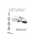
Model 988
Medical Video Camera
Operating & Maintenance Manual
WARNINGS AND CAUTIONS
WARNINGS AND CAUTIONS
TO AVOID POTENTIAL SERIOUS INJURY TO THE USER
AND THE PATIENT AND/OR DAMAGE TO THIS DEVICE,
THE USER MUST:
1.
Read this operating manual thoroughly and be familiar
with its contents prior to using this equipment.
2.
Carefully unpack the unit and check if any damage
occurred during shipment. If damage is detected,
please refer to the Service and Claims section in this
manual.
3.
Be a qualified physician, having complete knowledge of
the use of this equipment.
4.
Test this equipment prior to a surgical procedure. This
medical video camera was fully tested at the factory
before shipment.
5.
Avoid removing covers on control unit to avoid electric
shock and breaking of camera head seals.
6.
Attempt no internal repairs or adjustments not
specifically detailed in this operating manual.
7.
Pay close attention to the care, cleaning, sterilization,
and disinfection instructions in this manual. A deviation
may cause damage.
8.
DO NOT STERILIZE CAMERA CONTROL CONSOLE.
9.
Disconnect the control unit from the electrical outlet
when inspecting fuses.
Please read this manual and follow its instructions
carefully. The words WARNING, CAUTION, and NOTE
carry special meanings and should be carefully
reviewed:
WARNING
The personal safety of the patient may be
involved. Disregarding this information
could result in injury to the patient.
CAUTION
Special service procedures or precautions
must be followed to avoid damaging the
instrument.
NOTE
Special information to make maintenance
easier or important information more clear.
An exclamation mark within a triangle is
intended to alert the user to the presence
of important operating and maintenance
instructions in the literature accompanying
the product.
A lightning bolt within a triangle is intended
to warn of the presence of hazardous
voltage. Refer all service to authorized
personnel.
NOTE
Stryker Endoscopy reserves the right to make
improvements in the product(s) described
herein. Product(s) therefore may not agree in
detail to the published design or specifications.
All specifications are subject to change without
notice. Please contact the local Stryker
Endoscopy Distributor listed in the Other
Service section or phone your local Stryker
Endoscopy sales representative or agent for
information on changes and new products.
10. Read the entire instruction manual before assembling or
connecting the camera.
The camera warranty is void if any of these warnings are
disregarded.
Stryker Endoscopy accepts full responsibility for the effects
on safety, reliability, and performance of the equipment only
if:
•
Re-adjustments, modifications, and/or repairs are
carried out exclusively by Stryker Endoscopy.
•
The electrical installation of the relevant operating room
complies with the applicable IEC, CEC, and NEC
requirements.
WARNING
Ambient temperature range
Relative humidity range
Federal law (United States of America)
restricts this device to use by, or on order of a
physician.
Atmospheric pressure range
C
R
Denotes compliance to IEC 601-1 with
amendments 1 & 2, CSA Std. C22.2 No. 601.1M90, and UL Std. No. 2601-1.
Type BF Equipment as labeled on the product
Or
Type CF Equipment as labeled on the product
TABLE OF CONTENTS
TABLE OF CONTENTS
Product Description and Use..........................................................................................................
Description of Functions.............................................................................................................
Front Panel ...................................................................................................................
Rear Panel ....................................................................................................................
Attaching and Using the Coupler..................................................................................................
C-Mount Camera System............................................................................................................
Turning on the Camera................................................................................................................
Connecting Video Output.............................................................................................................
Electromagnetic Interference.......................................................................................................
Connecting the Camera Head......................................................................................................
White Balance............................................................................................................................
Gain..........................................................................................................................................
Auto focus.................................................................................................................................
Enhance....................................................................................................................................
Surgical Specialty.......................................................................................................................
Rear Panel Connections..............................................................................................................
Remote Accessory Control..........................................................................................................
LIGHT/ZOOM............................................................................................................................
BUTTON FUNCTION ..................................................................................................................
FLEX FILTER
.......................................................................................................................
AG FILTER
.......................................................................................................................
SHUTTER .................................................................................................................................
Camera Head Buttons.................................................................................................................
1
1
1
2
3
3
3
3
3
4
4
4
4
4
4
5
5
5
5
5
5
5
6
Sterilization & Disinfection.............................................................................................................
Cleaning....................................................................................................................................
Disinfection with Glutaraldehyde Solution......................................................................................
Sterilization with 100% Ethylene Oxide ........................................................................................
Sterilization with Steris® System.................................................................................................
Sterilization with Sterrad™ System..............................................................................................
Use of Sterile Drapes..................................................................................................................
Disposition of the Product...........................................................................................................
7
7
7
8
8
8
8
8
Interconnect Section.......................................................................................................................
System 1...................................................................................................................................
System 2...................................................................................................................................
System 3...................................................................................................................................
9
9
9
10
Troubleshooting............................................................................................................................. 11
Specifications................................................................................................................................. 12
Power Requirements.................................................................................................................... 12
Maintenance................................................................................................................................... 13
Fuse Replacement Instructions.................................................................................................... 13
Periodic Maintenance Schedule.................................................................................................... 13
Service & Claims............................................................................................................................. 14
Warranty......................................................................................................................................... 15
Other Service.................................................................................................................................. 16
PRODUCT DESCRIPTION & USE
A Stryker Endoscopy Model 988 Medical Video Camera
consists of a camera head, a coupler, a camera control unit,
and associated cables. These can be purchased together or
separately. Stryker Endoscopy considers instructional
training, or in-service, as an integral part of the Model 988
Medical Video Camera. Your local Stryker Endoscopy sales
representative will perform at least one in-service at your
convenience to help you set-up your equipment and instruct
you and your staff on its operation and maintenance. Please
contact your local Stryker Endoscopy representative to
schedule an in-service after your equipment has arrived.
The Stryker Endoscopy Model 988 Medical Video Camera is
designed for all types of video endoscopy applications. The
Model 988 camera, with the proper coupler, can be used with
most endoscopes or arthroscopes. Stryker Endoscopy’s
line of focusing camera couplers maximizes the surgeon’s
television viewing area for various endoscope sizes and
applications. The light sensitivity and color reproduction of
the Stryker Endoscopy system produces excellent picture
quality.
Description of Functions
2
3
4
5
6
1
7
Front Panel
1.
Power Switch - Turns camera on or off.
2.
White Balance - Begins WHITE BALANCE operation
3.
Gain - Selects four levels of light sensitivity settings.
4.
AUTO Focus - Turns Auto Focus on or off.
5.
Enhance ↑/↓ Buttons - Increases/decreases sharpness.
6.
Specialty - Selects Arthroscopy, Cystoscopy, Laparoscopy, Thoracoscopy surgical presets.
7.
Camera Connector - Connection for the camera head.
1
PRODUCT DESCRIPTION & USE
Description of Functions continued
9
8
2
17
10
18
11
12
19
13
20
14
21
22
15
23
8.
LIGHT/ZOOM- Selects either LIGHT or ZOOM function for the arrow buttons on camera head.
9.
Button Function - Enables/Disables functions on camera head right (‘W’) button.
10. Flex Filter - Enables/Disables Flexible Scope Filter.
11. AG Filter - Enables/Disables Anti-Glistening Filter.
12. Shutter - Enables/Disables Auto Shutter.
13. SDI Out - Serial Digital Interface (SDI) Video Output.
14. DVI Out 1 - Digital Video Interface (DVI) Video Output.
15. DVI Out 2 - Digital Video Interface (DVI) Video Output.
16. AC Power Input/Fuse - Input for AC Power and Fuse
17. Remote Out 1 - Output to Video Accessory Remote Switch.
18. Remote Out 2 - Output to Video Accessory Remote Switch.
19. RGB Out - RGB/Component Video Output.
20. S-VIDEO Out 1 - S-VIDEO Component Video Output.
21. S-VIDEO Out 2 - S-VIDEO Component Video Output.
22. Video Out - NTSC Composite Video Output.
23. Hermes - Hermes Operating Room Control Center Interface Connection.
16
PRODUCT DESCRIPTION & USE
ATTACHING AND USING
THE COUPLER
TURNING ON THE CAMERA
Connect the power cord supplied with the camera to the AC
inlet on the rear panel (16) and ensure that it is fully inserted.
Connect the other end to a hospital grade AC receptacle.
WARNING
Always use a hospital grade power cord with
this camera.
Press the power switch (1).
WARNING
Test the video camera before each procedure
begins. Ensure that a video image appears on
all video monitors before beginning each
procedure.
Figure 1
If a coupler is not already attached to the camera head when
received, screw the coupler into the front of the camera
head. Turn the coupler clockwise until it stops.
CONNECTING VIDEO OUTPUT
To attach an endoscope to the coupler, push down on the
eyepiece clamp (as shown above) and remove the red dust
cap if present. Push the eyepiece into the coupler and
release the eyepiece clamp. (See Figure 1).
CAUTION
Always treat the camera head with care.
Dropping the camera head could cause
damage.
C-MOUNT CAMERA SYSTEM
There are two camera heads: BF and CF applied part.
While both the BF and CF camera head may be used with
the 988 control unit, The CF model (Indentified by the heart
logo) is specially designed for procedures with direct cardiac
applications
WARNING:
When using more than one applied part
simultaneously, patient leakage current
may be additive. When using the 988 type
CF camera head for cardiac applications,
all other applied parts should be type CF
rated to minimize total patient leakage
current.
3
Figure 3
Connect the S-VIDEO or BNC cable provided with the
camera from VIDEO OUT to the VIDEO IN on a video
monitor (Figure 3) and turn on the monitor.
NOTE
When the camera head is not plugged into the
CAMERA connector (7), a color bar pattern will
appear on the video monitor.
WARNING
Do not touch the internal pin of the SDI and
VIDEO OUT BNC jacks (13,22) and the patient
simultaneously.
ELECTROMAGNETIC INTERFERENCE
The camera has been designed and tested to comply with
EN 60601-1-2: 1993 requirements for electromagnetic
compatibility with other devices. If interference is experienced, refer to the Troubleshooting section in this manual.
Figure 2
A direct-coupled endoscope may be attached to a C-mount
camera head by threading the endoscope directly into the
camera head. A coupler is not necessary in this case. (See
figure 2).
CAUTION: Do not over tighten endoscope, as this may
damage the front window of the camera.
PRODUCT DESCRIPTION & USE
CONNECTING THE CAMERA HEAD
AUTO FOCUS
The Auto Focus button (4) turn the Auto Focus feature on or
off. This feature maintains picture clarity throughout a larger
depth of field than the coupler manual focusing ring alone.
Press the Auto Focus button to activate/deactivate the
feature. Text displayed on the screen indicates the current
state of the feature. After activating the feature, establish a
good baseline focus using the coupler manual focusing ring,
and then press a short pulse on the camera head ‘W’ button
to set the baseline.
NOTE
When the Auto Focus feature is activated, the
enhance feature will be inoperative.
Hold here
ENHANCE ( ↑/↓ BUTTONS)
Figure 4
Unscrew (counter-clockwise) the soaking cap from the
camera cable. Holding the connector by the knobbed portion
only, plug the connector into the control unit by aligning the
red dot on the cable connector with the red dot on the
control unit CAMERA connector (7). Push in until it clicks
(Figure 4). A picture should now be visible on the video
monitor.
NOTE
4
CAUTION
To unplug the camera from the control unit,
grasp the knobbed portion of the connector
only and pull straight out. This releases the
connector latching mechanism.
To avoid camera head cable damage do not
severely bend, crush or cut the camera head
cable.
The Enhance button (5) feature increase or decrease the
picture sharpness. There are 8 levels of enhancement. Text
displayed on the screen indicates current enhancement
level.
Level 1
Level 8
=
=
No Enhancement
Maximum Enhancement
SURGICAL SPECIALTY
The Surgical Specialty selector switch (6) is used to select
one of four surgical type settings:
Arthroscopy - Shutter programming optimized for small
scopes, bright conditions, high contrast and low color.
WHITE BALANCE
Cystology - Shutter programming, color and lighting
optimized for urology procedures.
The WHITE BALANCE switch (2) is used to correct slight
color differences caused by using different light sources and
endoscopes. With the light source and scope attached, point
the scope at several stacked 4x4 white gauze pads, a white
laparoscopic sponge, or any clean white surface. Look at
the monitor and make sure that no glare is visible off of the
white surface.
Standard - Shutter programming optimized for large scopes
and high color differentiation.
Press and hold the WHITE BALANCE button until “WB”
begins flashing on the video monitor. Continue pointing the
scope at a clean, white surface until the video monitor
indicates that white balance is “OK.” The video picture will
change color. If the video monitor indicates that white
balance is “NOT GOOD,” repeat the process. If you cannot
achieve a White Balance that is “OK”, refer to the Troubleshooting section in this manual.
GAIN
The GAIN switch (3) increases the brightness of the video
picture. There are four levels of gain: OFF, LOW, MEDIUM,
and HIGH. Selecting a particular level establishes the GAIN
range. OFF is the setting you should normally use.
If the picture is too dark and the light source is at full
brightness, raise the light level by increasing the GAIN. The
picture will get brighter but may also be more grainy. Text
displayed on the screen indicates current gain level.
Thoracoscopy - Shutter programming, color and lighting
optimized for Thoracic procedures.
Manufacturer presets will optimize the video performance for
the surgery type selected. A green light will highlight the
current selection (see front panel).
PRODUCT DESCRIPTION & USE
REAR PANEL CONNECTIONS
LIGHT/ZOOM
There are four analog and three digital video outputs on
the rear panel. Analog outputs include one RGB (19)
output, one NTSC Composite output, and two S-VHS
outputs (20,21). Digital outputs include one SDI output
(13) and two DVI outputs (14,15). The DVI outputs can
also display analog XGA outputs through a DVI-I to
VGA adapter. These are separate outputs and can be
used together or independently.
The camera control unit has the ability to change the
function of the arrow buttons on the camera head. To
activate the zoom feature from the arrow buttons, place the
LIGHT/ZOOM switch (8) in the ZOOM position. To activate
the light level feature from the arrow buttons, place this
switch in the LIGHT position.
Additionally, there are two Remote outputs (17,18)
which can be used to control documentation equipment.
For more information about connecting the camera to
video peripherals, refer to the INTERCONNECT
section in this manual.
There is also one interface connection (23) for the
Hermes Operating Room Control Center. For more
information about using the Hermes System refer to the
Hermes Operating Room Control Center Operating
Manual.
REMOTE ACCESSORY CONTROL
The camera supports two remote outputs (17,18) for
controlling a Stryker SDC Pro, VCR, or other video
accessory. The camera head button can activate one
or two peripherals.
BUTTON FUNCTION
Place the BUTTON FUNCTION switch (9) ON to activate
the short pulse function (either zoom or gain) of the right
(‘W’) button on the camera head. Place this switch OFF to
deactivate the short pulse functions of the right camera head
button.
FLEX FILTER
The FLEX FILTER can be used to reduce the grid pattern
caused by a flexible scope (picture may blur). The Flex
Filter status can be toggled by changing the position of the
Flex Filter switch (10) or by pressing both enhancement
buttons (5) for at least one second. Graphics will indicate if
the Flex Filter is ON. Ensure the Flex Filter is OFF when
using rigid scopes.
AG FILTER
In order to use the remote outputs to interface with
different peripherals, two six-foot cables with 3.5mm
diameter ends, one six foot cable with a 2.5mm and a
3.5mm diameter end and two 2.5mm-to-3.5mm
adapters have been provided.
Position the AG FILTER switch (11) ON to reduce the
glistening or bright points of light caused by moisture
reflection. Position this switch OFF to deactivate the antiglistening (AG) filter.
Please refer to the Interconnect section in this manual.
SHUTTER SWITCH
Position the SHUTTER switch (12) ON/OFF to activate/
deactivate the automatic shutter.
ON:
The camera automatically adjusts the brightness
of the video picture in response to varying light
levels without using an automatic light source.
OFF:
The camera does not adjust to varying light
levels. You must use an automatic light
source to adjust picture brightness.
NOTE
You may use an automatic light source and
the camera auto shutter at the same time,
but the camera auto shutter should normally
be used alone.
5
PRODUCT DESCRIPTION & USE
CAMERA HEAD BUTTONS
‘↑’ AND ‘↓’ BUTTONS
↑ ’ and ‘↓
The ‘↑
↓’ buttons work together to increase or decrease the light level or zoom settings.
ZOOM: With the LIGHT/ZOOM switch in the ZOOM
position, the arrow buttons will raise or lower the magnification setting between 1.0 and 1.5 in 44 steps. Press the
button once for individual steps or hold down the button for a
quicker, smoother transition.
LIGHT LEVEL: With the LIGHT/ZOOM switch in the LIGHT
position, the arrow buttons will raise or lower the automatic
shutter light level setting in 64 steps. Press the button once
for individual steps or hold down the button for a quicker,
smoother transition.
Figure 5
As shown in Figure 5, the camera head contains a diamond↑’ to the north, ‘P’ to the
shaped, four-button pad, labeled ‘↑
↓’ to the south. These buttons
west, ‘W’ to the east, and ‘↓
provide for remote control of numerous functions. Appropriate audible feedback will accompany the various functions.
‘P’ BUTTON
6
The ‘P’ button controls up to two remote outputs. When
depressed less than one second, the button will activate
Remote 1.
When depressed longer than one second, the button will
activate Remote 2.
‘W’ BUTTON
The ‘W’ button activates several different functions, which
are selectable through external switches on the front and
rear panel.
(1) Depressing this button for more than one second will
activate the white balance function.
(2) If AUTO FOCUS is ON, depressing this button for less
than one second will establish a baseline for the
automatic focus.
(3) If AUTO FOCUS is OFF:
(a)
LIGHT/ZOOM switch to ZOOM – depressing this
button for less than one second will raise the gain
setting in four increments: 0dB, 5dB, 10dB and
15dB. When the gain setting reaches 15dB, the
next short push will cycle the setting back to 0dB.
(b)
LIGHT/ZOOM switch to LIGHT – depressing this
button for less than one second will expand the
magnification setting in four increments from 1.0
to 1.5. When the magnification setting reaches
1.5, the next short push will cycle the setting
back to 1.0.
(4) The above short pulse functions may be
disabled by placing the BUTTON FUNCTION
switch in the OFF position.
STERILIZATION AND DISINFECTION
Sterility of the camera head may be achieved by use of
sterile drapes, ethylene oxide gas, the Steris® system and
Sterrad™.
WARNING
CAUTION
NOTE
Camera head, coupler and camera cable must
be cleaned and sterilized prior to first and
every subsequent use.
The following procedures do not guarantee
sterilization or disinfection. Sterility or
disinfection can only be achieved if properly
trained personnel follow these recommended
procedures and hospital practices.
DISINFECTION WITH
GLUTARALDEHYDE SOLUTION
NOTE
Never soak the camera head in the same tray
with scalpels or other sharp instruments. Avoid
soaking dissimilar metals in close proximity in
order to minimize galvanic corrosion. Camera
malfunction caused by damaged cables is not
covered by your warranty.
CAUTION
Before soaking, inspect the camera head cable
for breaks or cuts. A break or cut in the cable
will allow the solution to seep into the camera
head and cause damage. Please return any
camera with a damaged cable to Stryker
Endoscopy Repair Department.
Soaking the coupler (adapter) separate from
the camera head is not recommended.
Moisture may get trapped between the
coupler and camera head and cause fogging.
1.
Clean and prepare as recommended in the Cleaning
section. Ensure the soaking cap is installed.
2.
Camera head, adapter, and camera head cable should
be immersed in Cidex Plus® glutaraldehyde solution or
Cidex OPA® solution for disinfecting. Specifications for
each is as follows:
CLEANING
1.
Immediately after use, unplug the camera head
connector and protect it with the soaking cap. Place the
cap over the connector and turn clockwise until secure.
CAUTION
2.
6
Install the soaking cap before rinsing camera
to prevent corrosion of the connector pins.
Ensure cap is properly tightened.
Cidex Plus® disinfection:
soak time:
minimum of ten minutes as
recommended by the sterilant
manufacturer.
temperature:
25° C (77°F)
Rinse the camera head and camera head cable in
lukewarm tap water. Use mild enzymatic detergent and
a soft brush to remove resistant debris. Ensure
removal of bioburden from all surfaces.
3.
Thoroughly rinse off all soap residue with water.
4.
Apply alcohol to glass surfaces with soft cotton
applicator to aid in cleaning and drying without leaving
spots or streaks.
5.
Dry thoroughly with soft towel or gauze surgical
sponge.
6.
Before disinfection or sterilization, coil the camera head
cable into a loop about ten inches in diameter, avoiding
kinks and twists in the cable. During disinfection or
sterilization, ensure that the camera head and cable are
not placed on top of other pieces of equipment.
If the camera control unit needs to be cleaned, wipe it down
with a damp cloth or sponge and towel dry.
Cidex OPA® disinfection:
soak time:
minimum of 12 minutes as
recommended by the sterilant
manufacturer.
temperature:
20°C (68°F)
3.
After soaking, the camera head, coupler, and cable
must be rinsed with sterile water and thoroughly
agitated to remove all traces of glutaraldehyde solution.
Before use, dry thoroughly with a sterile towel. Ensure
the soaking cap and connector are completely dry
before removing the cap.
7
STERILIZATION AND DISINFECTION
STERILIZATION:
USE OF STERILE DRAPES
100% ETHYLENE OXIDE GAS:
Use of sterile drapes will ensure maximum longevity of your
Stryker Endoscopy Model 988 Medical Video Camera.
Follow instructions provided by drape manufacturer when
using sterile drapes. Sterile camera drapes for use with the
Model 988 Medical Video Camera can be ordered under
Stryker product number 240-010-200.
1.
Clean and prepare as recommended on page 7.
Ensure the soaking cap is installed.
2.
Sterility has been validated using an ethylene oxide
sterilization unit for a cycle with the following
parameters:
temperature:
humidity:
vacuum:
preconditioning time:
sterilant mixture:
sterilant concentration:
exposure time:
aeration:
55°C
70% RH±5%
21 in Hg
60 minutes
100% ethylene oxide
600±5 mg/L ethylene
oxide
120 minutes
12 hours, 55°C
STERIS® SYSTEM:
1.
Clean and prepare as recommended on page 7.
Ensure the soaking cap is installed.
2.
Sterility has been validated using Steris® System 1 with
Steris® Sterilant 20.
CAUTION
Maximum performance and camera life is
extended by the consistent use of a single
sterilization method. Also, avoid leaving the
camera in the sterilization solutions longer than
necessary as this will accelerate normal
product aging.
DISPOSITION OF THE PRODUCT
The device must be disposed of according to local laws and
hospital practices. The device does not contain any
hazardous materials.
STERRAD™ SYSTEM:
1.
Clean and prepare as recommended on page 7.
Ensure the soaking cap is installed.
2.
Sterility has been validated using Sterrad™ Sterilization
System.
8
NOTE
To increase the longevity of the camera head,
observe the following process limits:
maximum ethylene oxide exposure time:
3 hours
maximum temperature:
60°C (140°F)
maximum Cidex® Glutaraldahyde soak time: 24 hours
NOTE
If coupler and camera head are sterilized or
disinfected as a single unit, disconnecting the
coupler will compromise the sterility or
disinfection.
7
INTERCONNECT SECTION
Two types of cables are used in wiring the 988 Video Output:
NOTES:
•
•
•
If you are using a non-Stryker light source with an
unterminated input, you must connect a NTSC cable
from the VIDEO OUT of the light source to the VIDEO
IN on the monitor.
•
An additional monitor may be connected using any open
camera output.
•
You may also connect an S-VHS or BNC cable between
the camera and monitor and select the appropriate
video source.
NTSC cables which have a BNC connector
S-VHS cables which have a 4 pin Mini-Din connector
BNC connectors are push and turn type connectors while SVHS cables are push only type connectors. On some
monitors, S-VHS inputs may be labeled Y/C, S-VHS and
describe the same input. Described in this section are three
typical set-ups. Match your equipment and wire them
according to the appropriate diagram.
9
SYSTEM 1
SYSTEM 2
Equipment Used: Camera, Light Source and Monitor
Equipment Used: Camera, Light Source, Video Peripheral
and Monitor. The video peripheral may be a video printer,
digital capture, Hermes or VCR.
INTERCONNECT SECTION
10
SYSTEM 3
Equipment Used: Camera, Light Source, Stryker Printer,
Stryker VCR, Monitor.
TROUBLESHOOTING
PROBLEM
SOLUTION
NO COLOR BAR
•
Ensure video out from camera is connected to the video monitor and all video
systems are powered on
PICTURE COLOR INCORRECT
•
•
White balance against clean white surface, see WHITE BALANCE section
Check color settings on monitor
PICTURE TOO DARK
•
•
•
•
Adjust light source for higher output
Check fiber optic light cable for excessive broken fibers
Press GAIN switch to increase illumination
Set auto SHUTTER to OFF
PICTURE TOO BRIGHT
•
•
•
Adjust light source for lower output
Select auto SHUTTER mode
Ensure GAIN is OFF
NOISE OR SNOW ON PICTURE
(no electro-cautery)
•
•
•
•
Ensure GAIN is OFF
Reduce Enhancement
Select auto SHUTTER mode to OFF
Check and replace faulty video cables
NOISE OR SNOW ON PICTURE
WHEN USING ELECTRO-CAUTERY
•
•
•
Plug electro-cautery into separate electrical outlet and separate power cords
Separate camera cable and electro-cautery cable
Reposition electro-cautery grounding pad on patient
•
Check to ensure that all components in the video systems are plugged in and power
is on
Check connector on camera head cable for broken pins
NO VIDEO PICTURE WHEN
CAMERA HEAD IS PLUGGED IN
IMAGE NOT CENTERED
•
•
12
VARIABILITY IN COLOR
REPRODUCTION WITH VARIOUS
LIGHT SOURCES OR PERIPHERALS
FOGGY PICTURE
(loss of definition & clarity)
CLEANING DIRTY OPTICS
•
•
•
WHITE BALANCE the camera
Check settings on video peripherals
Ensure light source has proper infrared filter (check with manufacturer
specifications)
•
•
•
Check camera focus and refocus
Optics are dirty. Clean and dry both the scope and the coupler glass face.
Moisture may exist between the camera head and the coupler. Remove coupler
from the camera head and clean this area thoroughly.
•
•
Rotate the scope. If dust particles in the picture rotate, dust is located on the scope
itself. Follow manufacturer’s instructions for cleaning the eyepiece and negative lens.
If particles do not move when rotating, particles are behind the scope. Remove the
scope and clean the window on the front of the coupler with a dry or alcohol tipped
cotton swab.
If dust particles lie between the coupler and camera, remove the coupler and clean
the window on the coupler and the window on the camera head.
BE SURE entire area is completely dry before reassembling or fogging may result.
•
•
Check that coupler is in focus.
Check that the Flex Filter switch is turned off.
•
•
•
Picture too dark (see above for troubleshooting)
Picture too bright (see above for troubleshooting)
Color temperature too low - WB with light source connected and use
metal halide or xenon lighting (no fluorescent lighting).
•
•
BLURRY PICTURE
NO WHITE BALANCE (WB)
NOTE:
Release scope from the coupler and re-connect. Make sure the scope is seated
correctly in the coupler.
If this troubleshooting guide does not solve the problems that you are having with your camera, please refer to the
Service and Claims section in this manual for instructions on obtaining repair service from Stryker Endoscopy.
11
SPECIFICATIONS
Imaging System
1/3” Interline Transfer, EX view HAD CCD
768 (H) x 494 (V) pixels
Scanning System
Horizontal:
Vertical:
2:1 Interlaced
15.734 kHz
59.94 Hz
Video Outputs
Composite:
Connector:
Component:
Connector:
12
One NTSC standard
1.0V P-P into 75 Ohms
BNC coaxial
Two S-VHS
Y-1.0V P-P C-0.29V P-P
4-Pin S-VHS
Digital:
Connector:
Digital:
Connector:
Resolution
Horizontal:
Vertical:
950 lines
500 lines
Signal to Noise Ratio
72 dB
Mounting
Endoscope Eyepiece used with coupler
C-mount camera head used with C-mount scopes
(C-mount 1”-32UN-2A)
Minimum Illumination
< 1.0 Lux
Auto Shutter Range
1/60 to 1/50,000 second
Gain
OFF
LOW
MEDIUM
HIGH
0 dB
5 dB
10 dB
15 dB
Operating Temperature
5° to 40°
Transport & Storage
Temperature
Relative Humidity
Atmospheric Pressure
5° to 40° C
10% to 85%
700 hPa to 1060 hPa
Power Consumption
approx. 30 W
Input Voltage Range
100/120 VAC 50/60 Hz
Total Shipping Weight
13 lbs (5.9 kg)
Dimensions
Camera Control Unit:
Camera Head Cable
to Camera Control Unit:
Two Digital Video Interface (DVI)
1024X768 XGA resolution
29-pin DVI-I
One Serial Digital Interface (SDI)
SMPTE-259M
BNC Coaxial
9.8”w x 4.0”h x 15”d (24.8cm w X 10.1cm h X 38.1cm d)
10 foot (3m) sealed cable or 21.3 foot (6.5m) sealed cable (sensed by CCU)
Enhancement
Switchable to 8 steps
Classification & Approvals
Complies with IEC 601-1 with Amendments 1 & 2, CSA Std. c22.2 No. 601.1 - M90, and UL
Std. No. 2601-1
Complies with EN 60601-1-2: 1993 (EMC compliance of medical devices)
Type BF applied part or Type CF applied part as labeled on the product
Class I equipment
Ordinary equipment
Continuous operation
13
MAINTENANCE
FUSE REPLACEMENT
INSTRUCTIONS
1.
Unplug the camera control unit from the wall socket and
remove the power cord from the camera control unit.
2.
Unlatch the fuse holder above the AC Inlet (16) and
remove. You may need to press the tab on the fuse
holder with a slender screwdriver to release the latch.
3.
Replace the fuse with the same value and rating.
WARNING
4.
14
To avoid the risk of fire, replace only with a
fuse of the value specified on the fuse label
(located on the rear panel of the camera
control unit).
Reinstall the fuse holder until the tab snaps in place.
PERIODIC MAINTENANCE SCHEDULE
WARNING
To ensure safe operation of the Model 988
Medical Video Camera you should perform the
following procedure periodically:
Activity:
Check earth leakage current to <500µA
(<300µA in U.S.A.), ground impedance to <0.1
ohms, and power consumption less than or
equal to rated power.
When:
Every 12 months.
Tools and Equipment Required:
True RMS digital multimeter and safety analyzer.
Refer calibration and operating difficulties not detailed in this
manual to your Stryker Endoscopy sales representative, or
Stryker Endoscopy Customer Service (in the United States:
1-800-624-4422), or the nearest Stryker Endoscopy
subsidiary (refer to the Other Service section in this
manual).
13
SERVICE & CLAIMS
SERVICE
NOTE
Never open the camera head or its cable.
These units have been factory sealed to
prevent moisture from entering the electronic
components. If the camera head or the cable
seal is intentionally broken, the equipment
warranty will be void.
NOTE
The medical video camera described in this
manual is constantly being reviewed and
improvements may be made without notice.
If service is needed either during or after the warranty
period:
1.
Contact Stryker Endoscopy at 1-800-624-4422 or
phone your local Stryker Endoscopy sales
representative.
2.
Package all the components carefully in the
original shipping container if possible.
3.
Ship the camera, pre-paid and insured to:
Stryker and Stryker Endoscopy are registered trademarks of Stryker Corporation.
Stryker Endoscopy Customer Service
Attention: Repair Department
5900 Optical Court
San Jose, CA 95138
14
15
WARRANTY
Stryker Endoscopy warrants the Model 988 Medical Video
Camera against defects in both materials and workmanship
to the registered owner at the time of purchase. All components including the charge coupled device (CCD) located in
the camera head are covered by the warranty for a period of
one year from the date of purchase.
This warranty does not apply to any unit which has been
subject to misuse, neglect, improper installation or that which
has been altered, adjusted, or tampered with by any person
other than Stryker Endoscopy authorized personnel.
If upon examination by authorized service personnel, it is
determined that the malfunction is due to misuse, or abuse,
warranty provisions will not apply. An estimate of the cost of
repair work will be given to the customer prior to servicing
and repairing the unit.
The customer is responsible for returning the defective
equipment to the factory at his or her own expense. Stryker
Endoscopy or its representative will service the unit, repair
or replace any defective parts thereof, and return the unit.
If, upon examination, it is determined that the fault has been
caused by misuse or abnormal conditions of operation, the
repairs will be billed to the customer as out-of-warranty
repairs.
16
Instruments repaired under Stryker Endoscopy’s standard
repair program will be issued a thirty day warranty against
defects in both materials and workmanship, provided the
original warranty period has passed. Instruments submitted
due to defects in materials and workmanship during the
warranty period will be repaired at no charge to the customer.
The warranty as set forth herein is exclusive and in lieu of all
other warranties, remedies, obligations and liabilities of
Stryker Endoscopy Inc., expressed or implied, including the
implied warranties of merchantability and fitness for use and
of consequential damages. These products are being sold
only for the purpose described herein, and such warranty
only runs to the purchaser. In no event shall Stryker
Endoscopy be liable for any breach of warranty in any
amount exceeding the purchase price of the product.
No agent, employee or representative of Stryker Endoscopy
has the authority to bind the Company to any other warranty,
affirmation, or representation concerning this instrument.
This warranty is valid only to the original purchaser of
Stryker Endoscopy products directly from Stryker Endoscopy or from a Stryker Endoscopy authorized agent. The
warranty cannot be transferred or assigned by the original
purchaser.
15
OTHER SERVICE
For service in the U.S.A., call your Stryker Endoscopy representative or Stryker Endoscopy Customer Service at 1-800-624-4422.
Outside of the U.S.A., please contact your Stryker Endoscopy distributor at one of the following locations:
Stryker Corporation
2725 Fairfield Road
Kalamazoo, MI 49002
USA
Phone:
1-616-385-2600
Telex:
224464 STRYKER KMZ
Fax:
1-616-385-1996
Stryker Korea
11F Dong Sung Bldg. 154-24
Samsung-dong, Kangnam-ku
Seoul
KOREA 135-090
Phone:
82-2-565-7303
Fax:
82-2-552-4156
Stryker Canada
3375 North Service Road
Unit C-9
Burlington, Ontario
L7N 3G2
CANADA
Phone:
905-332-3235
Fax:
905-332-7674
Stryker Australia
50 Broughton Road
Artarmon NSW 2064
AUSTRALIA
Phone:
61-2-9420-0522
Fax:
61-2-9420-0633
Stryker Deutschland GmbH
Gewerbeallee 18
D-45478 Mulheim an der Ruhr
GERMANY
Phone:
49-208-999060
Fax:
49-208-9990666
16
Stryker Taiwan
5F-1,23 Pa Te Road
Section 1, Taipei, TAIWAN, R.O.C.
Phone:
886-2-2322-2895
Fax:
886-2-2357-8543
Stryker U.K.
Stryker House, Hambridge Road
Hambridge Road Industrial Estate
Newbury RG14 5EP
United Kingdom
ENGLAND
Phone:
44-1635-262400
Fax:
44-1635-36400
Stryker B.V.
Marinus van Meelweg 17
5657 En Eindhoven
THE NETHERLANDS
Phone:
31-40-2922522
Fax:
31-40-2922555
Stryker France
Z.A.C. Paris-Nord 11
13, Rue de la Perdrix
93290 Tremblay les Gonesse
FRANCE
Phone:
33-1-48175038
Fax:
33-1-48632175
Stryker Pacific Headquarters
Suite 2501, Citibank Tower
Citibank Plaza
3 Garden Road
HONG KONG
Phone:
852-2840-4400
Fax:
852-2804-6303
Stryker Singapore (ASEAN)
70 Bendemeer Road
#03-32 Hiap Huat House
SINGAPORE 339940
Phone:
65-293-0119
Fax:
65-293-7028
Stryker Osteonics, SA
Via della Posta, PO Box 254
6934 Bioggio
SWITZERLAND
Phone:
41-91-610-4410
Fax:
41-91-610-4421
Stryker India
India Office
First Floor C-5
SDA Commercial Complex
New Delhi 110016
INDIA
Phone:
91-11-686-6742
Fax:
91-11-696-6020
Nippon Stryker K.K.
25-3 Yoyogi 3-Chome
Shibuya-ku, Tokyo 151-0053
JAPAN
Phone:
81-03-5352-9211
Fax:
81-03-5352-9204
17
18
OTHER SERVICE
Stryker China
Room 832 Capital Times Square
No. 88 West Chang An Street
Beijing 100031
P. R. CHINA
Phone:
852-2814-7463
Fax:
852-2873-0210
Stryker Europe Headquarters
Cite-Centre, Grand Rue 92
CH-1820 Montreux
SWITZERLAND
Phone:
41-21-966-1201
Fax:
41-21-966-1200
Stryker AB Scandinavia
Krossverksgatan 3
2-216 16 Malmö
SWEDEN
Phone:
46 40-69-18-136
Fax:
46 40-69-18-190
Stryker A/S Denmark
Krossverksgatan 3
2-216 16 Malmö
SWEDEN
Phone:
45 3677 9966
Fax:
45 3677 8666
Stryker Latin America
Plaza Royale Suite 304
15600 NW 67th Ave.
Miami Lakes, Florida 33014
USA
Phone:
1-305-821-1888
Fax:
1-305-826-0067
Stryker Finland
PL 80 (Makelankatuz)
FIN 00501 Helsinki
FINLAND
Phone:
+358 (0) 9 7744 680
Fax:
+358 (0) 9 7744 6820
Stryker Middle East / Africa
1404 Al Masaoud Bldg. Suite 604
Hamdan Street
Abu Dhabi
U.A.E.
Phone:
9712-6312145
Fax:
9712-6313698
MANUFACTURER
Stryker Mexico, S.A. de C.V.
Montecito No. 38
Piso 12, Oficina 31
Colonia Napoles
MEXICO 03810
Phone:
525-488-0890
Fax:
525-488-0891
NV Stryker SA (Belgium)
Ikaros Business Park Fase III
Ikaroslaan 12
1930 Zaventem
BELGIUM
Phone:
32-2-717-92-10
Fax:
32-2-717-92-49
Stryker Chile
Avenida Nueva Tajamer 481
Oficina 805 Piso 8
Torre Norte, Santiago
CHILE
Phone:
562-244-3600
Fax:
562-244-3696
Stryker Spain
Manuel Tovar 35
28034 Madrid
SPAIN
Phone:
34-91-7283500
Fax:
34-91-3580748
Stryker Endoscopy Inc.
5900 Optical Court
San Jose, CA 95138
USA
Phone:
1-408-754-2000
Fax:
1-408-754-2505
17
5900 Optical Court, San Jose, CA 95138 USA. 1-408-754-2000
1000-400-558 Rev. E
1-800-624-4422