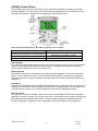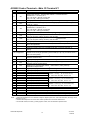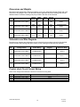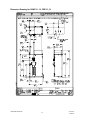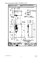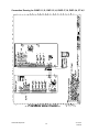
1
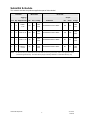
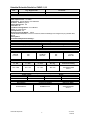
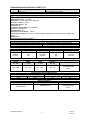
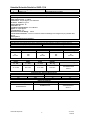
HPPG 89ki EXPANSION PROJECT VFD Submittal Data Spec 15855 Project Submittal for Honda 89KI Expansion Specification: 15855 Engineering Contact: SSOE Contractor: Addison Smith Architect: End Customer (User): Honda Submitted By: BJ Borie, Borie-Davis Inc Revision: A Date: 01/06/14 Submittal Schedule This schedule includes the products supplied as part of this submittal. Motor Data1 Schedule Drive Data Tagging / Item Qty Equipment ID Output HP FLA Voltage Product ID HP Amps Voltage 1 2 CHWP11,12 125 156 460 VAC ACH550-BCR-157A-4+B055 125 157 480 VAC 2 2 CWP-13,14 100 124 460 VAC ACH550-BCR-125A-4+B055 100 124 480 VAC 3 2 ICWP-17,18 20 27 460 VAC ACH550-BCR-031A-4+B055 20 31 480 VAC 4 4 PWP-3,4, CT-4,5 60 77 460 VAC ACH550-BCR-078A-4+B055 60 77 480 VAC Notes: 1. AC Motor Data is per National Electrical Code Table 430.250 for typical motors used in most applications and is provided as typical data only. DC motor data is per typical industry standards. Actual motor data may vary. Honda 89KI Expansion 2 37170101 01/06/14 Submittal Schedule Details for CHWP-11,12 Item Tag / Equipment ID 1 Product ID CHWP-11,12 ACH550-BCR-157A-4+B055 Item Description Input Voltage: 480 VAC Rated Output Current: 157 AMPS Construction: E-clipse-Bypass, Circuit Breaker Enclosure: NEMA/UL Type 12 Nominal Horsepower: 125 Frame Size: R6 Input Disconnecting Means: Circuit Breaker Bypass: E-Clipse Bypass Input Impedance: 5% Short Circuit Current Rating: 100 kA Communication Protocols: Johnson Controls N2, Siemens Buildings Technologies FLN (P1), Modbus RTU, BACnet Other Options: Recommended Spare Parts Package : Drive Input Fuse Ratings (Note: Drive is UL approved without the need for input fuses. Fuse rating information provided for customer reference) Amps (600 V) 200 Circuit Breaker Bussmann Type 170M1370 or M2617 Wire Size Capacities of Power Terminals Disconnect Switch Terminal Block Overload Relay 350MCM 274 in-lbs N/A N/A Height in / mm Width in / mm 54.3 / 1380 28.1 / 713 N/A N/A 250 MCM 300 in-lbs Dimensions and Weights Depth Weight in / mm lbs / kg 19 / 483 Ground Lug 360 / 163 3 x #3/0 250 in-lbs Dimension Drawing 3AUA0000016382 Sheet 1 Heat Dissipation & Airflow Requirements Power Losses Watts 2310 Power Wiring BC00R046PW-A Honda 89KI Expansion Airflow BTU/Hr 7884 CFM 238 Reference Drawings Connection Diagram BCBDR016CC-A 3 CM/Hr 405 Dimension Detail 3AUA0000016382 Sheet 1 37170101 01/06/14 Submittal Schedule Details for CWP-13,14 Item Tag / Equipment ID 2 Product ID CWP-13,14 ACH550-BCR-125A-4+B055 Item Description Input Voltage: 480 VAC Rated Output Current: 124 AMPS Construction: E-clipse-Bypass, Circuit Breaker Enclosure: NEMA/UL Type 12 Nominal Horsepower: 100 Frame Size: R5 Input Disconnecting Means: Circuit Breaker Bypass: E-Clipse Bypass Input Impedance: 5% Short Circuit Current Rating: 100 kA Communication Protocols: Johnson Controls N2, Siemens Buildings Technologies FLN (P1), Modbus RTU, BACnet Other Options: Recommended Spare Parts Package : Drive Input Fuse Ratings (Note: Drive is UL approved without the need for input fuses. Fuse rating information provided for customer reference) Amps (600 V) 200 Circuit Breaker Bussmann Type 170M1370 or M2617 Wire Size Capacities of Power Terminals Disconnect Switch Terminal Block Overload Relay 350MCM 274 in-lbs N/A N/A Height in / mm Width in / mm 54.3 / 1380 28.1 / 713 250 MCM 300 in-lbs N/A N/A Dimensions and Weights Depth Weight in / mm lbs / kg 19 / 483 Ground Lug 266 / 121 3 x #3/0 250 in-lbs Dimension Drawing 3AUA0000016382 Sheet 1 Heat Dissipation & Airflow Requirements Power Losses Watts 1940 Power Wiring BC00R046PW-A Honda 89KI Expansion Airflow BTU/Hr 6621 CFM 99 Reference Drawings Connection Diagram BCBDR016CC-A 4 CM/Hr 168 Dimension Detail 3AUA0000016382 Sheet 1 37170101 01/06/14 Submittal Schedule Details for ICWP-17,18 Item Tag / Equipment ID 3 Product ID ICWP-17,18 ACH550-BCR-031A-4+B055 Item Description Input Voltage: 480 VAC Rated Output Current: 31 AMPS Construction: E-clipse-Bypass, Circuit Breaker Enclosure: NEMA/UL Type 12 Nominal Horsepower: 20 Frame Size: R3 Input Disconnecting Means: Circuit Breaker Bypass: E-Clipse Bypass Input Impedance: 5% Short Circuit Current Rating: 100 kA Communication Protocols: Johnson Controls N2, Siemens Buildings Technologies FLN (P1), Modbus RTU, BACnet Other Options: Recommended Spare Parts Package : Drive Input Fuse Ratings (Note: Drive is UL approved without the need for input fuses. Fuse rating information provided for customer reference) Amps (600 V) 60 Circuit Breaker Bussmann Type JJS-60 Wire Size Capacities of Power Terminals Disconnect Switch Terminal Block Overload Relay #1 50 in-lbs N/A N/A Height in / mm Width in / mm 37.4 / 950 20.5 / 521 #2 50 in-lbs N/A N/A Dimensions and Weights Depth Weight in / mm lbs / kg 15.3 / 389 Ground Lug 120 / 54.4 #2 50 in-lbs Dimension Drawing 3AUA0000016379 Sheet 1 Heat Dissipation & Airflow Requirements Power Losses Watts 457 Power Wiring BC00R024PW-A Honda 89KI Expansion Airflow BTU/Hr 1560 CFM 79 Reference Drawings Connection Diagram BCBDR016CC-A 5 CM/Hr 134 Dimension Detail 3AUA0000016379 Sheet 1 37170101 01/06/14 Submittal Schedule Details for PWP-3,4, CT-4,5 Item Tag / Equipment ID 4 Product ID PWP-3,4, CT-4,5 ACH550-BCR-078A-4+B055 Item Description Input Voltage: 480 VAC Rated Output Current: 77 AMPS Construction: E-clipse-Bypass, Circuit Breaker Enclosure: NEMA/UL Type 12 Nominal Horsepower: 60 Frame Size: R4 Input Disconnecting Means: Circuit Breaker Bypass: E-Clipse Bypass Input Impedance: 5% Short Circuit Current Rating: 100 kA Communication Protocols: Johnson Controls N2, Siemens Buildings Technologies FLN (P1), Modbus RTU, BACnet Other Options: Recommended Spare Parts Package : Drive Input Fuse Ratings (Note: Drive is UL approved without the need for input fuses. Fuse rating information provided for customer reference) Amps (600 V) 100 Circuit Breaker Bussmann Type JJS-100 Wire Size Capacities of Power Terminals Disconnect Switch Terminal Block Overload Relay #1 50 in-lbs N/A N/A Height in / mm Width in / mm 37.4 / 950 20.5 / 521 #2/0 120 in-lbs N/A N/A Dimensions and Weights Depth Weight in / mm lbs / kg 15.3 / 389 Ground Lug 138 / 62.6 #2 50 in-lbs Dimension Drawing 3AUA0000016379 Sheet 1 Heat Dissipation & Airflow Requirements Power Losses Watts 1295 Power Wiring BC00R024PW-A Honda 89KI Expansion Airflow BTU/Hr 4420 CFM 165 Reference Drawings Connection Diagram BCBDR016CC-A 6 CM/Hr 280 Dimension Detail 3AUA0000016379 Sheet 1 37170101 01/06/14 ACH550 Product Overview Description The ACH550 series is a microprocessor based Pulse Width Modulated (PWM) adjustable speed AC drive. The ACH550 drive takes advantage of sophisticated microprocessor control and advanced IGBT power switching technology to deliver high-performance control of AC motors for a wide range of HVAC applications. With drives ranging from 1 to 550 HP, the ACH550 series features a universal full graphic interface that “speaks” to the operator in plain English phrases, greatly simplifying set-up, operation, and fault diagnosis. The ACH550 is also programmable in fourteen other languages. Each ACH550 drive comes equipped with an extensive library of pre-programmed HVAC application macros which, at a touch of a button, allow rapid configuration of inputs, outputs, and performance parameters for specific HVAC applications to maximize convenience and minimize start-up time. The ACH550 series can handle the most demanding commercial applications in an efficient, dependable, and economic manner. Honda 89KI Expansion 7 37170101 01/06/14 ACH550 Standard Features UL, cUL labeled and CE marked, BTL listed st EMI/RFI Filter (1 Environment, Restricted Distribution) Seismic Certificate of Compliance in accordance with IBC 2000 referencing ASCE 7-98 and ICC AC156 IBC 2003 referencing ASCE 7-02 and ICC AC156 IBC 2006 referencing ASCE 7-05 and ICC AC156 IBC 2009 referencing ASCE 7-05 and ICC AC156 Start-Up Assistants Maintenance Assistants Diagnostic Assistants Real Time Clock Includes Day, Date and Time Operator Panel Parameter Backup (read/write) Full Graphic and Multilingual Display for Operator Control, Parameter Set-Up and Operating Data Display: Output Frequency (Hz) / Motor Speed (RPM) Motor Current 2 Calculated Energy Savings ($, kWh/MWh, CO ) Calculated % Motor Torque Calculated Motor Power (kW) DC Bus Voltage Output Voltage Heatsink Temperature Elapsed Time Meter (reset-able) KWh (reset-able) Input / Output Terminal Monitor PID Actual Value (Feedback) & Error Fault Text Warning Text Three (3) Scalable Process Variable Displays User Definable Engineering Units Two (2) Programmable Analog Inputs Six (6) Programmable Digital Inputs Two (2) Programmable Analog Outputs Up to six (6) Programmable Relay Outputs (Three (3) Standard) Adjustable Filters on Analog Inputs and Outputs Mathematical Functions on Analog Reference Signals All Control Inputs Isolated from Ground and Power Four (4) Resident Serial Communication Protocols BACnet (MS/TP) Johnson Controls N2 Siemens Building Technologies FLN (P1) Modbus RTU Input Speed Signals Current 0 (4) to 20 mA Voltage 0 (2) to 10 VDC Increase/Decrease Reference Contacts (Floating Point) Serial Communications Start/Stop 2 Wire (Dry Contact Closure) 3 Wire (Momentary Contact) Application of Input Power Application of Reference Signal (PID Sleep/Wake-Up) Serial Communications Start Functions Ramp Flying Start Pre-magnetization (DC Brake) on Start Automatic Torque Boost Automatic Torque Boost with Flying Start Auto Restart (Reset) – Customer Selectable and Adjustable Stop Functions Ramp or Coast to Stop Emergency Stop DC Braking / Hold at Stop Flux Braking Accel/Decel Two (2) sets of Independently Ramps Linear or Adjustable ‘S’ Curve Accel/Decel Ramps Honda 89KI Expansion 8 HVAC Specific Application Macros Separate Safeties (2) and Run Permissive Inputs Damper Control Override Input (Fire Mode) Timer Functions Four (4) Daily Start/Stop Time Periods Four (4) Weekly Start/Stop Time Periods Four Timers for Collecting Time Periods and Overrides Seven (7) Preset Speeds Supervision Functions Adjustable Current Limit Electronic Reverse Automatic Extended Power Loss Ride Through (Selectable) Programmable Maximum Frequency to 500 Hz PID Control Two (2) Integral Independent Programmable PID Setpoint Controllers (Process and External) External Selection between Two (2) Sets of Process PID Controller Parameters PID Sleep/Wake-Up Motor Control Features Scalar (V/Hz) and Vector Modes of Motor Control V/Hz Shapes Linear Squared Energy Optimization IR Compensation Slip Compensation Three (3) Critical Frequency Lockout Bands Preprogrammed Protection Circuits Overcurrent Short Circuit Ground Fault Overvoltage Undervoltage Input Phase Loss Output Device (IGBT) Overtemperature Adjustable Current Limit Regulator 2 UL508C approved Electronic Motor Overload (I T) Programmable Fault Functions for Protection Include Loss of Analog Input Panel Loss External Fault Motor Thermal Protection Stall Underload Motor Phase Loss Ground Fault Input Impedance 5% Equivalent Impedance with Internal Reactor(s) Patented Swinging Choke Design for Superior Harmonic Mitigation (R1…R6 Frames) 3% Equivalent Impedance (R8 Frame) OPTIONAL FEATURES 3 Relay Extension Module (OREL-01) 115/230 V Digital input Interface Card (OHDI-01) Fieldbus Adapter Modules LonWorks BACnet IP to MS/TP Router Profibus DeviceNet Ethernet ControlNet DriveWindow Light Start-up, Operation, Programming and Diagnostic Tool Fan Replacement Kit 37170101 01/06/14 ACH550 Specifications Input Connection Input Voltage (U1).................................................................... 208/220/230/240 VAC 3-phase +/-10% 208/220/230/240 VAC 1-phase +/-10% 380/400/415/440/460/480 VAC 3-phase +/-10% Frequency: ............................................................................. 48 - 63 Hz Line Limitations: ..................................................................... Max +/-3% of nominal phase to phase input voltage Fundamental Power Factor (cos : ...................................... 0.98 at nominal load Connection: ............................................................................ U1, V1, W1 (U1, V1, 1-phase) Output (Motor) Connection Output Voltage: ...................................................................... 0 to U1, 3-phase symmetrical, U2 at the field weakening point Output Frequency: ................................................................. -500 to 500 Hz Frequency Resolution: ........................................................... 0.01 Hz Continuous Output Current: Variable Torque: .................................................... 1.0 * I2N (Nominal rated output current, Variable Torque) Short Term Overload Capacity: Variable Torque: ..................................................... 1.1 * I2N, (1 min/10 min) Peak Overload Capacity: Variable Torque: ..................................................... 1.35 * I2N, (2 sec/1 min) Base Motor Frequency Range: ............................................... 10 to 500 Hz Switching Frequency: ............................................................. 1, 4, 8 or 12 kHz Acceleration Time: ................................................................. 0.1 to 1800 s Deceleration Time: ................................................................. 0.1 to 1800 s Efficiency: ............................................................................... 0.98 at nominal power level Short Circuit Withstand Rating: .............................................. 100,000 AIC (UL) w/o fuses Connection: ............................................................................ U2, V2, W2 Enclosure Style: ....................................................................................... UL (NEMA) Type 1, Type 12, or Type 3R Agency Approval Listing and Compliance:.......................................................... UL, cUL, CE Ambient Conditions, Operation 0 0 0 0 0 Air Temperature: ..................................................................... -15 to 40 C (5 to 104 F), above 40 C the maximum output current is 0 0 0 de-rated 1% for every additional 1 C (up to 50 C (122 F) maximum limit. Relative Humidity: ................................................................... 5 to 95%, no condensation allowed, maximum relative humidity is 60% in the presence of corrosive gasses Contamination Levels: IEC:......................................................................... 60721-3-1, 60721-3-2 and 60721-3-3 Chemical Gasses:................................................... 3C1 and 3C2 Solid Particles: ........................................................ 3S2 Installation Site Altitude:.......................................................... 0 to 1000 m (3300 ft) above sea level. At sites over 1000 m (3300 ft) above sea level, the maximum power is de-rated 1% for every additional 100 m (330 ft). If the installation site is higher than 2000 m (6600 ft) above sea level, please contact your local ABB distributor or representative for further information 2 2 Vibration:................................................................................. Max 3.0 mm (0.12 in) 2 to 9 Hz, Max 10 m/s (33 ft/s ) 9 to 200 Hz sinusoidal Seismic Certified referencing IBC 2000, 2003, 2006 and 2009 Ambient Conditions, Storage (in Protective Shipping Package) 0 0 0 0 Air Temperature: ..................................................................... -40 to 70 C (-40 to 158 F) Relative Humidity: ................................................................... Less than 95%, no condensation allowed Vibration:................................................................................. In accordance with ISTA 1A and 1B specifications 2 2 Shock (IEC 60086-2-29): ........................................................ Max 100 m/s (330 ft/s ) 11 ms Ambient Conditions, Transportation (in Protective Shipping Package) 0 0 0 0 Air Temperature: ..................................................................... -40 to 70 C (-40 to 158 F) Relative Humidity: ................................................................... Less than 95%, no condensation allowed Atmospheric Pressure:............................................................ 60 to 106 kPa (8.7 to 15.4 PSI) 2 2 Vibration:................................................................................. Max 3.5 mm (0.14 in) 2 to 9 Hz, Max 15 m/s (49 ft/s ) 9 to 200 Hz sinusoidal 2 2 Shock (IEC 60086-2-29): ........................................................ Max 100 m/s (330 ft/s ) 11 ms Free Fall:................................................................................. R1: 76 cm (30 in) R2: 61 cm (24 in) R3: 46 cm (18 in) R4: 31 cm (12 in) R5 & 6: 25 cm (10 in) Cooling Information Cooling Method:...................................................................... Integral fan(s) Power Loss: ........................................................................... Approximately 3% of rated power Honda 89KI Expansion 9 37170101 01/06/14 ACH550 Specifications (continued) Analog Inputs Quantity................................................................................... Two (2) programmable Voltage Reference: ................................................................. 0 (2) to 10 V, 312kOhm, single ended Current Reference: ................................................................. 0 (4) to 20 mA, 100Ohm, single ended Potentiometer:......................................................................... 10 VDC, 10 mA (1K to 10KOhms) Input Updating Time................................................................ 8 ms 2 Terminal Block Size ................................................................ 2.3mm / 14AWG Reference Power Supply 0 0 Reference Voltage .................................................................. +10 VDC, 1% at 25 C (77 F) Maximum Load ....................................................................... 10 mA Applicable Potentiometer ........................................................ 1 kOhm to 10 kOhm 2 Terminal Block Size ................................................................ 2.3mm / 14AWG Analog Outputs Quantity................................................................................... Two (2) programmable current outputs Signal Level ............................................................................ 0 (4) to 20 mA 0 0 Accuracy ................................................................................. +/- 1% full scale range at 25 C (77 F) Maximum Load Impedance..................................................... 500 Ohms Output Updating Time............................................................. 2 ms 2 Terminal Block Size ................................................................ 2.3mm / 14AWG Digital Inputs Quantity................................................................................... Six (6) programmable digital inputs Isolation................................................................................... Isolated as one group Signal Level ............................................................................ 24 VDC, (10V Logic 0) Input Current ........................................................................... 15 mA at 24 VDC Input Updating Time:............................................................... 4 ms 2 Terminal Block Size ................................................................ 2.3mm / 14AWG Internal Power Supply Primary Use ............................................................................ Internal supply for digital inputs Voltage:................................................................................... +24 VDC, max 250 mA Maximum Current: .................................................................. 250 mA Protection:............................................................................... Short circuit protected Relay Outputs Quantity................................................................................... Three (3) programmable relay (Form C) outputs Switching Capacity:................................................................. 8 A at 24 VDC or 250 VAC, 0.4 A at 120 VDC Max Continuous Current: ........................................................ 2A RMS Contact Material:..................................................................... Silver Cadmium Oxide (AgCdO) Isolation Test Voltage ............................................................. 4 kVAC, 1 minute Output Updating Time............................................................. 12 ms 2 Terminal Block Size ................................................................ 2.3mm / 14AWG Protections Single Phase........................................................................... Protected (input & output) Overcurrent Trip Limit: ............................................................ 3.5 x I2N instantaneous Adjustable Current Regulation Limit: ...................................... 1.1 x I2N (RMS) max. Overvoltage Trip Limit:............................................................ 1.30 x UN Undervoltage Trip Limit:.......................................................... 0.65 x UN Overtemperature (Heatsink): .................................................. +115°C (+239°F) Auxiliary Voltage: .................................................................... Short Circuit Protected Ground Fault: .......................................................................... Protected Short Circuit: ........................................................................... Protected Microprocessor fault:............................................................... Protected Motor Stall Protection:............................................................. Protected Motor Overtemperature Protection (I2t): ................................. Protected Input Power Loss of Phase: .................................................... Protected Loss of Reference:.................................................................. Protected Short Circuit Current Rating:................................................... 100,000 RMS symmetrical Amperes Input Line Impedance: ............................................................ Swinging choke 5% equivalent R1-R6, 3% equivalent R8 U1 = Input Voltage U2 = Output Voltage PN = Power – Normal Duty (HP) UN = Nominal Motor Voltage fN = Nominal Motor Frequency I2N = Nominal Motor Current – Normal Duty Specifications are subject to change without notice. Please consult the factory when specifications are critical. Honda 89KI Expansion 10 37170101 01/06/14 ACH550 Control Panel The ACH550 Control Panel is a multifunction control panel with full graphic LCD display and multiple language capability. The control panel can be connected to and detached from the ACH550 at any time. The panel can be used to upload and copy parameters to other ACH550 drives. Run Indication and Shaft Direction located in upper left corner of display. Control Panel Display Significance Drive is running and at set point Shaft direction is forward or reverse Drive is operating but not at setpoint Drive is stopped Rotating arrow (clockwise or counterclockwise) Rotating arrow blinking Stationary arrow LED Indicators The green LED indicates that the power is on and the drive is operating normally. The red LED indicates a fault. A blinking green LED indicates an alarm condition. A blinking red LED indicates a fault that requires power to be cycled off and on to reset the drive. Fault Indications The ACH550 Control Panel can display over 20 alarm and fault messages. The last fault and previous faults (1 to 9) are retained in memory. The last fault and previous faults (1 & 2) also record important diagnostic information to assist in troubleshooting. Most faults can be reset by pressing the RESET key (Soft Key 1). Parameters Application specific parameters are immediately accessible through a selection of start-up “Assistants”. A complete list of parameters is also available grouped by function in approximately 33 menu groups. One of the basic menu functions can be used to display the complete list of changed parameters. Real Time Clock The Operator Control Panel includes a real time clock which provides Day, Date and Time information, displayed in a choice of formats. The real time clock has a 10 year battery back up and provides time and date stamping of drive faults and other events. The clock is also used by the ACH550s internal timer functions, providing an integral time clock for start/stop control as well as other control operations. Honda 89KI Expansion 11 37170101 01/06/14 Control Modes When the HAND key is pressed, the drive starts and pressing the UP/DOWN keys can modify the reference frequency. The HAND (keypad) control mode is indicated. When the OFF key is pressed, the drive stops and the OFF control mode is indicated. When the AUTO key is pressed, the AUTO control mode is indicated. The drive can be started and stopped using whichever remote start/stop command has been configured, a contact closure applied to the start/stop input, a serial communication command or a process feedback signal. In AUTO mode the drive speed is typically controlled by the external speed reference input or by the PID controller. If the HAND key is pressed while the drive is running in the AUTO control mode, the drive continues to run without changing speed, but ceases to respond to external input or PID speed reference changes. (Bumpless transfer) Pressing the UP/DOWN keys can modify the reference frequency. If the AUTO key is pressed while the drive is running in the HAND control mode and an external start command is present, the drive continues to run and follows the acceleration or deceleration control ramp to the speed set by the external input or PID speed reference. (Bumpless transfer) Cable Connections Terminal Description U1, V1, W1 3~ power supply input PE / GND U2, V2, W2 Uc+, UcX1 1 to 18 X1 19 to 27 X1 28 to 32 Protective Ground Power output to motor DC bus Control Wiring Control Wiring Serial Communications Note Use of 1~ supply requires 50% derate of output current and is applicable for 208 to 240 VAC operation only. Follow local rules for cable size. Low voltage control – Use shielded cable Low voltage or 115VAC Use shielded cable Follow local codes for cable size. To avoid electromagnetic interference, use separate metallic conduits for input power wiring, motor wiring, control and communications wiring. Keep these four classes of wiring separated in situations where the wiring is not enclosed in metallic conduit. Also, keep 115VAC control wiring separated from low voltage control wiring and power wiring. Use shielded cable for control wiring. Ampacity is based on the use of 60 °C rated power cable up to 100 Amps (75 °C over 100 Amps). Refer to the included tables for current ratings, fuse recommendations and maximum wire size capacities and tightening torques for the terminals. The ACH550 is suitable for use on a circuit capable of delivering not more than 100,000 RMS symmetrical amperes, 480 V maximum. The ACH550 has an electronic motor protection feature that complies with the requirements of the National Electric Code (NEC). When this feature is selected and properly adjusted. Additional overload protection is not required unless more than one motor is connected to the drive or unless additional protection is required by applicable safety regulations. For CE installation requirements, see ABB publication CE-US-02 “CE Council Directives and Variable Speed Drives.” Contact your local ABB representative for specific IEC installation instructions. Honda 89KI Expansion 12 37170101 01/06/14 ACH550 Control Terminals - Main I/O Terminal X1 X1 1 Identification SCR 2 AI 1 3 AGND 4 10 V 5 AI 2 6 AGND 7 AO1 8 AO2 9 AGND 10 24 V 11 GND 12 DCOM DI Configuration1 13 DI 1 14 DI 2 15 DI 3 16 DI 4 17 18 19 20 21 22 23 24 25 26 27 28 29 30 31 32 DI 5 DI 6 RO1C RO1A RO1B RO2C RO2A RO2B RO3C RO3A RO3B Screen B A AGND Screen Notes: Description Terminal for signal cable screen. (Connected internally to chassis ground.) Analog input channel 1, programmable. Default2 = External reference Resolution 0.1 % accuracy ±1 %. 0 (4) - 20 mA (Ri = 312 k) (J1:AI1 ON) 0 (2) - 10 V (Ri = 100 ) (J1:AI1 OFF) Analog input common. (Connected internally to chassis ground through 1 M) 10 V/10 mA reference voltage output for analog input potentiometer, accuracy ±2 %. (1 k R 10 k Analog input channel 2, programmable. Default2 = PID Feedback Resolution 0.1 % accuracy ±1 %. 0 (4) - 20 mA (Ri = 312 k) (J1:AI2 ON) 0 (2) - 10 V (Ri = 100 ) (J1:AI2 OFF) Analog input common. (Connected internally to chassis ground through 1 M) Analog output channel 1, programmable. Default2 = Output frequency 0 (4) - 20 mA (load < 500 ), accuracy ±3% full scale. Analog output channel 2, programmable. Default2 = Output current 0 (4) - 20 mA (load < 500 ), accuracy ±3% full scale. Analog output common. Connected internally to chassis ground through 1 M) Auxiliary voltage output 24 V DC / 250 mA (Reference to AGND). Short circuit protected. Common for digital input (DI) return signals. Digital input circuit common for all digital inputs (DIs). Connected internally as floating. To activate a digital input, there must be +10 V (or -10 V) between that input and DCOM. The 24 V may be provided by the ACH550 (X1:10) or by an external 12-24 V source of either polarity. Digital input 1, programmable. Default2 = Start/Stop (AUTO mode) Activation starts the drive Digital input 2, programmable. Default2 = Not configured. Digital input 3, programmable. Default2 = Constant (Preset) speed. Activation selects constant speed 1 Digital input 4, programmable. Default2 = Start enable 1 (safety interlock) Deactivation stops the drive. Digital input 5, programmable. Default2 = Not configured. Digital input 5, programmable. Default2 = Not configured. Relay output 1, programmable Common Normally Closed (NC) (Default2 = Ready – 19 connected to 21). Normally Open (NO) 12 - 250 V AC / 30 V DC, 10 mA - 2 A Relay output 2, programmable Common Normally Closed (NC) (Default2 = Running - 22 connected to 24). Normally Open (NO) 12 - 250 V AC / 30 V DC, 10 mA - 2 A Relay output 3, programmable Common Normally Closed (NC) (Default2 = Fault (-1)3- 25 connected to 27). Normally Open (NO) 12 - 250 V AC / 30 V DC, 10 mA - 2 A Terminal for signal cable screen. (Connected internally to chassis ground.) RS-485 Serial Communications Positive input connection RS-485 Serial Communications Negative input connection Analog input common. (Connected internally to chassis ground through 1 M.) Terminal for signal cable screen. (Connected internally to chassis ground.) 1. Digital input impedance 1.5 k Maximum voltage for digital inputs is 30 V. Use multi-strand wire, size range: 20-16 2 AWG (0.5-1.5 mm ) 2. Default values depend on the macro used. Values specified are for the HVAC default macro. 3. For fail-safe reasons, the Fault (-1) Relay signals a “Fault”, when the ACH550 is powered down. Honda 89KI Expansion 13 37170101 01/06/14 ACH550 with ABB E-Clipse bypass – Overview ABB E-Clipse bypass Standard Features Door Interlocked Disconnect or Circuit Breaker English Language Back-Lit LCD Display Operator Control Panel LED Status Pilot Lights Smoke Control Override Mode Serial Communications 5 Programmable Relay Outputs (Form C) 100% Functionality with Drive Removed Programmable Auto Transfer to Bypass Plain English Safety Annunciation UL & cUL Listed Seismic Zone 4 Certified (IBC 2006) UL Type 1, Type 12 or Type 3R Enclosure Programmable Class 10, 20, or 30 OL Automatic Restart 24 Month Parts and Labor Warranty (with Certified Start-up) Two Contactor Bypass System Status Display Bypass Diagnostics Display Drive Exclusive Fast-Acting Fuses Electronic Motor Overload Protection Damper Control - VFD and Bypass Modes 6 Digital Inputs (5 programmable) Single Phase Protection in VFD & Bypass Mode Bullet Proof Contactor Protection Serial Communications Pass Through I/O Proof-of-Flow Indication & Action Conformal Coated Circuit Boards +30%; -35% Input Voltage Tolerance Run Permissive Circuit Supervisory Control UL Listed I2T Electronic Overload UL Listed and tested 100,000 Ampere SCCR (VCR and BCR Units) The ACH550 with ABB E-Clipse bypass is an ACH550 HVAC Drive in an integrated UL Type 1, UL Type 12 or NEMA 3R enclosure with a bypass motor starter. The ACH550 with ABB E-Clipse bypass provides an input disconnect switch or circuit breaker with door mounted and interlocked operator (padlockable in the OFF position), a bypass starter, electronic motor overload protection, a local programming and operator keypad with indicating lights, provisions for external control connections, and serial communications capability. Certain configurations (+F267) also provide a drive service switch. UL Type 1 (NEMA 1) and UL Type 12 (NEMA 12) E-Clipse units are available from 1 to 100 HP at 208/240V, 1 to 400 HP at 480V, and 2 to 150 HP at 600V. UL Type 1 and UL Type 12 units are wall mounted from 1 to 200 HP and floor mounted from 250 to 550 HP. The operator keypad is mounted on the door of the enclosure. For outdoor applications, UL Type 3R (NEMA 3R) E-Clipse unit are available from 1 to 100 HP at 208/240V, 1 to 200 HP at 480V and 2 to 150 HP at 600V. Construction is sheet steel with a tough powder coat paint finish for corrosion resistance. A thermostatically controlled space heater and thermostatic control of the force ventilated cooling system are standard. The operator keypads are mounted on the enclosure door and covered by a hinged panel. The ACH550 with ABB E-Clipse bypass includes two contactors. One contactor is the bypass contactor, used to connect the motor directly to the incoming power line in the event that the ACH550 is out of service. The other contactor is the ACH550 output contactor that disconnects the ACH550 from the motor when the motor is operating in the Bypass mode. The drive output contactor and the bypass contactor are electrically interlocked to prevent “back feeding”. Honda 89KI Expansion 14 37170101 01/06/14 The ACH550 with ABB E-Clipse bypass is a microprocessorcontrolled “intelligent” system which features programmable Class 20 or 30 overload curves, programmable underload (broken belt) and overload trip or indication. Also included as standard features are single-phase protection in bypass mode, programmable manual or automatic transfer to bypass, fireman’s override, smoke control, damper control, no contactor chatter on brown-out power conditions and serial communications. Should a drive problem occur, fast acting fuses exclusive to the ACH550 drive path disconnect the drive from the line prior to clearing upstream branch circuit protection, maintaining bypass capability. Damper Control Circuit (Run Permissive) The damper control circuit closes a dry contact upon a start command to open a damper such as an outdoor air damper, fire damper, isolation damper, etc. before the motor is allowed to operate in drive mode or bypass mode regardless of the source of the run command. When the damper is fully open, a normally open dry contact from the damper end-switch closes and allows the motor to operate. Up to four dedicated inputs are provided for safety interlocks such as firestats, smoke detectors, etc. The safety interlock inputs may also be linked to plain English keypad diagnostic indications to be displayed on the LCD. The unit may be set-up to display any of the following diagnostics upon opening of a digital input: Vibration Switch; Firestat; Freezestat; Over Pressure; Vibration Trip; Smoke Alarm; Safety Open; Low Suction; Start Enable; Run Enable; Damper End Switch; Valve Open Proof; or Pre-Lube Cycle. When any of these contacts open, the motor stops (in drive or bypass mode) and the damper is commanded to close. Although it is not a recommend sequence of operation, this run permissive circuit may also be controlled via serial communications. Smoke Control and Override Modes The ACH550 with ABB E-Clipse bypass has two Override modes of operation for critical control situations. The Smoke Control Override accepts a normally open dry contact that forces the motor to run in bypass and ignores all keypad inputs. In Smoke Control Override mode, the system acknowledges high priority digital inputs such as overpressure safeties and damper end-switch run permissive proofs, and disregards other, low priority digital inputs. See the attached sample wiring diagram for further details. Smoke Control Override (Override 1) response is not field programmable. The unit will go into smoke Override mode whenever DI6 is closed. Honda 89KI Expansion 15 37170101 01/06/14 Honda 89KI Expansion 16 37170101 01/06/14 The second mode, Override 2, is fully programmable. Override 2 default programming is designed for “Run to Destruction” operation. However, the end user can program the unit to acknowledge some external inputs while ignoring others, ignore all external inputs or acknowledge all external inputs. This mode is fully programmable to allow the user to program the response of the unit to match his local AHJ. Serial communications All ABB E-Clipse bypass units have the following Embedded Fieldbus (EFB) protocols included as standard: Modbus RTU; Johnson Controls N2; Siemens Building Technologies FLN (P1); and BACnet (MS/TP). The ACH550 with ABB E-Clipse bypass has the ability to monitor VFD/Bypass mode of operation, the status of the bypass H-O-A switch, bypass fault and override status over serial communication. In addition, the user can monitor and / or control over 45 points of bypass information via the communications protocols. Serial communication capabilities include - bypass run-stop control; the ability to force the unit to bypass; and the ability to control all relay outputs. The DDC system can monitor bypass feedback such as, current (in amps), kilowatt hours (resettable), operating hours (resettable), and bypass logic board temperature. The DDC system is also capable of monitoring the bypass relay output status, and all digital input status’. All bypass diagnostic warning and fault information is transmitted over the serial communications bus. Remote system (drive or bypass) fault reset is possible. Vertical & Standard ABB E-Clipse bypass Exterior Views Honda 89KI Expansion 17 37170101 01/06/14 ABB E-Clipse bypass Operator Control ACH550 Control Panel The ACH550 Control Panel is a keypad with an LCD unit that provides status indication and operator controls for the ACH550 drive. In normal operation with the ABB E-Clipse bypass, the ACH550 should be placed in the Auto mode of operation by pressing the Auto key on the ACH550 Control Panel. Refer to the ACH550 User’s Manual for additional information on the ACH550 Control Panel and other aspects of ACH550 operation. Bypass Control Keypad The ABB E-Clipse bypass has a separate keypad with an LCD unit that provides status indication and programming of the system. This keypad is also used for selecting the Drive or Bypass mode of operation and manually starting and stopping the motor in the Bypass mode. The bypass keypad has LED indicating lights that indicate the status of both the bypass and the drive as well as an LCD display that provides programming, status and warning/fault indications. The illustration below shows the bypass control keypad and identifies the keys and LED indicating lights. The functions of the various keys and LEDs are described in the following table. Honda 89KI Expansion 18 37170101 01/06/14 Enabled LED Drive Selected LED Bypass Selected LED Motor Run LED Drive Faulted LED Bypass Faulted LED Drive Key Bypass Key Auto Key Off/Reset Key Hand Key UP Key Down Key Honda 89KI Expansion The Enabled LED is illuminated green under the following conditions: Both the Safety Interlock(s) and Run Enable contacts are closed. The Safety Interlock(s) contact are closed with no Start command present. The Enable LED flashes green if the Run Enable contact is open and when the Safety Interlock contact(s) are closed and a Start command is present. The Enable LED is illuminated red when the Safety Interlock contact(s) are open. The Drive Selected LED is illuminated green when the drive has been selected as the power source for the motor and no drive fault is present. The Bypass Selected LED is illuminated green when the bypass has been selected as the power source for the motor and no bypass fault is present. The Motor Run LED is illuminated green whenever the system is running. The Motor Run LED flashes green to indicate the system has been placed in an Override operating mode. The Drive Fault LED is illuminated red when the bypass has lost its’ communications link with the drive or when the motor or drive protection functions have shut down the drive. The Bypass Faulted LED is illuminated or flashes red when the motor or bypass protective functions have shut down the bypass. The Drive Key selects the drive as the power source for the motor. The Bypass Key selects the bypass as the power source for the motor. The Auto key selects the Auto Start contact or serial communications as the means for starting and stopping the motor in the bypass mode. The Off/Reset key may be used to manually stop the motor if the motor is running on bypass power. The Off/Reset Key also resets most bypass faults. It may take several minutes before the bypass can be reset after an overload trip. If a bypass fault condition is present, the second push of the Off/Reset key puts the bypass in the Off mode. The Hand key can be used to manually start the motor when the bypass has been selected as the power source for the motor. Used to navigate through system programming steps. Used to navigate through system programming steps. 19 37170101 01/06/14 Control Modes Drive mode Under normal conditions the system is in the Drive mode. The ACH550 drive provides power to the motor and controls its speed. The source of the drive’s start/stop and speed commands is determined by the Auto or Hand mode selection of the drive’s keypad. Commands come from the control terminals or serial communications when the Auto mode has been selected or from the drive keypad when the Hand mode has been selected. The user can normally switch to the Drive mode by pressing the Drive key on the bypass keypad. Bypass mode In the Bypass mode, the motor is powered by AC line power through the bypass contactor. The source of the bypass’start/stop commands is determined by the Auto or Hand mode selection of the bypass’ keypad. Commands come from the control terminals or serial communications when the Auto mode has been selected or from the bypass keypad when the Hand mode has been selected. The user can normally switch to the Bypass mode by pressing the Bypass key on the bypass keypad. Smoke Control mode In the Smoke Control (Override 1) mode, the motor is powered by AC line power through the bypass contactor. The source of the Smoke Control command is DI 6 and is unaffected by external stop commands. The VFD Keypad and the Bypass Keypad will not accept user commands when the system is in Smoke Control mode (the keypad user inputs are disabled). The user can switch to the Smoke Control mode by closing the Smoke Control input contact (DI 6). When the Smoke Control input contact is closed, the system is forced to bypass and runs the motor. The Motor Run LED flashes green when the system is in override. While in Smoke Control, the system only responds to certain inputs. Normally when the Smoke Control input contact is switched from closed to open, the system returns to the operating mode that existed prior to entering Smoke Control and can once again be controlled using the Drive and Bypass keys. The exception to this is when the Bypass Override (Override 2) input contact is closed, in which case the system switches to Bypass Override operation. Bypass Override mode In the Bypass Override (Override 2) mode, the motor is powered by AC line power through the bypass contactor. The source of the start command is internal and unaffected by external stop commands. The VFD Keypad and the Bypass Keypad will not accept user commands when the system is in Bypass Override mode (the keypad user inputs are disabled). The user can switch to the Bypass Override mode by closing the Bypass Override input contact (DI 5-if programmed). When the Bypass Override input contact is closed, the system is forced to bypass and does not respond to the Drive and Bypass keys. The Motor Run LED flashes green when the system is in override. While in Bypass Override the system responds to bypass overloads and programmed faults. The system may be custom programmed to acknowledge or disregard certain faults, safeties and enables. The unit is default programmed to ignore all external safeties and run enables. See Group 17 for programmability of the digital input and fault functions. Normally when the Bypass Override input contact is switched from closed to open, the system switches to the Drive mode and can be controlled using the Drive and Bypass keys. The exception to this is when the Smoke Control (Override 1) input contact is closed, in which case the system remains in Smoke Control operation. Hand mode When the system is in the Bypass mode, the operator can manually start the motor by pressing the Hand key. The motor will run and the Hand LED will be illuminated green. In order to run the motor, the Safety Interlock and Run Enable contacts must be closed (green Enable LED) and any bypass fault must be reset. Auto mode In the Auto mode the bypass start/stop command comes from the Start/Stop input terminal on the bypass control board or from serial communications – if programmed. The Auto mode is selected by pressing the Honda 89KI Expansion 20 37170101 01/06/14 Auto key on the bypass keypad. The Auto LED is illuminated green when the bypass is in the Auto mode. If the system is in the Bypass mode, the motor will run across the line if the Auto mode is selected, the Start/Stop, Safety Interlock and Run Enable contacts are closed and any bypass fault is reset. Off Mode If the motor is running in the Bypass mode, the operator can manually stop the motor by pressing the OFF key. The Motor Running LED will go out. The motor can be restarted by pressing the Hand key or the bypass can be returned to the Auto mode by pressing the Auto key. If the system is in the Drive mode, pressing the OFF key will take the bypass out of the Auto mode, but will not affect motor operation from the drive. If the system is switched to the Bypass mode, a motor that is running will stop. Programmable Relay Contact Outputs The ABB E-Clipse bypass has five programmable relay outputs as standard. The default programming descriptions for these relay outputs is described below. Bypass Not Faulted The Bypass Not Faulted relay is energized during normal operation. The Bypass Not Faulted relay is deenergized when a bypass fault has occurred. System Running The System Running relay is energized when the ABB E-Clipse bypass System is running. The System Running relay provides an output when the motor is running whether powered by the ACH550 drive or the bypass. System Started The System Started relay is energized when the ABB E-Clipse bypass system is started. Three conditions must be met in order for the relay to energize. 1) a Start command must be present, 2) the Safety Interlock input contact must be closed and 3) there can be no fault present in the system. The Start command can come from the bypass control board terminal block, the ACH550 keypad, the bypass keypad, or serial communications depending on the operational mode selected. The System Started relay is ideal for use in damper actuator circuits, opening the dampers only under those conditions where the system is preparing to run the motor. The System Started relay will de-energize, closing the dampers if the safeties open, the system faults, or when a Stop command is issued. Honda 89KI Expansion 21 37170101 01/06/14 Bypass Selected Relay output four is factory default programmed for Bypass Selected. The relay will be energized anytime the user has placed the system in Bypass mode. Bypass Auto Relay Output five is factory default programmed for Bypass Auto. The relay will be energized anytime the user has placed the bypass in the Auto mode. The complete list of programmable relay output functions follows: 0 = NOT SEL 1 = SYS READY 2 = SYS RUNNING 3 = SYS STARTED 4 = BYPASS SEL 5 = BYPASS RUN 6 = BYPASS FLT 7 = BYP NOT FLT 8 = BYPASS ALRM 9 = DRIVE FAULT 10 = DRV NOT FLT 11 = DRIVE ALARM 12 = OVERRIDE 13 = BYPASS HAND 14 = BYPASS OFF 15 = BYPASS AUTO 16 = COM CTRL 17 = SYS ALARM 18 = BYPASS FLT/ALM 19 = BYP OVERLD 20 = BYP UNDERLD 21 = PCB OVERTMP 22 = SYS UNDERLD 23 = SYSTEM FLT 24 = SYS FLT/ALM 25 = SYS EXT CTL 26 = SYS OVERLD 27 = CONTACT FLT Cable Connections The following illustrations show the ACH550 with ABB E-Clipse bypass cable connection points for the various enclosure styles. The illustrations indicate the location of input and output power connections as well as equipment and motor grounding connection points. ACH550 drives are configured for wiring access from the bottom only on Vertical ABB E-Clipse bypass units and from the top only on Standard ABB E-Clipse bypass units. At least three separate metallic conduits are required, one for input power, one for output power to the motor and one for control signals. All ABB E-Clipse bypass units provided with a circuit breaker input - VCR and BCR configurations have a panel short circuit current rating of 100,000 RMS symmetrical Amperes. Units provided with a disconnect input - VDR and BDR configurations require separate external low peak fuses (supplied by others) to obtain the 100,000 KAIC SCCR. Terminal Sizes Power and motor cable terminal sizes are shown in the Submittal Schedule Details and in the Wire Size Capacities of Power Terminals Table. The information provided is for connections to an input circuit breaker or disconnect switch, a motor terminal block, overload relay and ground lugs. The table also lists torque that should be applied when tightening the connections. Protections All ABB E-Clipse bypass units include the following protective features: single phase input and output; motor open phase; motor overload (UL Listed); stuck contactor; contactor coil open; undervoltage; motor underload (proof-of-flow / broken belt); serial communications loss; and overtemperature. All printed circuit boards are conformally coated as standard. Honda 89KI Expansion 22 37170101 01/06/14 Internal Layout Drawings Vertical ABB E-Clipse Bypass (UL Type 1 / 12) Standard Wall Mount ABB E-Clipse Bypass Standard Floor Mount ABB E-Clipse Bypass Honda 89KI Expansion 23 37170101 01/06/14 Control Terminals The control wiring includes connections to an analog speed command signal and a start/stop relay contact for controlling the motor in the AUTO mode. There may also be connections to external run enable interlock contacts and a connection from the Motor Run contact to an external status indication circuit. For a detailed description of the control circuit functions and alternate Control Connection diagrams, refer to the ACH550 with ABB E-Clipse bypass Users Manual. Basic Control Connections for Damper Actuator Control Honda 89KI Expansion 24 37170101 01/06/14 Engineering Data and Ratings Tables Fuses Drive input fuses are recommended to disconnect the drive from power in the event that a component fails in the drive’s power circuitry. Recommended drive input fuse specifications are listed in the Submittal Schedule Details and in the Fuse Ratings Table. Fuse rating information is provided for customer reference. Item 1 2 3 4 Drive Input Fuse Ratings Amps (600V) Bussmann Type Catalog Number ACH550-BCR-157A-4+B055 ACH550-BCR-125A-4+B055 ACH550-BCR-031A-4+B055 ACH550-BCR-078A-4+B055 200 200 60 100 170M1370 or M2617 170M1370 or M2617 JJS-60 JJS-100 Terminal Sizes / Cable Connection Requirements Power and motor cable terminal sizes and connection requirements are shown in the Submittal Schedule Details and in the Terminal Sizes / Cable Connection Requirements Table. The information provided below is for connections to input power and motor cables. These connections may be made to an input circuit breaker or disconnect switch, a motor terminal block, overload relay, and/or directly to bus bars and ground lugs. The table also lists torque that should be applied when tightening terminals and spacing requirements where multiple mounting holes are provided in the bus bar. Item Catalog Number Circuit Breaker Disconnect Switch 1 ACH550-BCR-157A-4+B055 350MCM 274 in-lbs N/A N/A 2 ACH550-BCR-125A-4+B055 350MCM 274 in-lbs N/A N/A 3 ACH550-BCR-031A-4+B055 #1 50 in-lbs N/A N/A 4 ACH550-BCR-078A-4+B055 #1 50 in-lbs N/A N/A Terminal Block Overload Relay Ground Lug N/A N/A 3 x #3/0 250 in-lbs N/A N/A 3 x #3/0 250 in-lbs N/A N/A #2 50 in-lbs N/A N/A #2 50 in-lbs 250 MCM 300 in-lbs 250 MCM 300 in-lbs #2 50 in-lbs #2/0 120 in-lbs Heat Dissipation Requirements The cooling air entering the drive must be clean and free from corrosive materials. The Submittal Schedule Details and the Heat Dissipation Requirements table below give the heat dissipated into the hot air exhausted from the drives. If the drives are installed in a confined space, the heat must be removed from the area by ventilation or air conditioning equipment. Item 1 2 3 4 Catalog Number ACH550-BCR-157A-4+B055 ACH550-BCR-125A-4+B055 ACH550-BCR-031A-4+B055 ACH550-BCR-078A-4+B055 Honda 89KI Expansion Power Losses Watts BTU/Hr 2310 7884 1940 6621 457 1560 1295 4420 25 CFM 238 99 79 165 Airflow CM/Hr 405 168 134 280 37170101 01/06/14 Dimensions and Weights Dimensions and weights of the drives provided are given in the Submittal Schedule Details and in the Dimensions and Weights Table. The table also lists the applicable dimension drawings that include additional detail. Dimension drawings may be provided in the back of this submittal. 1 ACH550-BCR-157A-4+B055 Height mm / in 1380 / 54.3 ACH550-BCR-125A-4+B055 1380 / 54.3 713 / 28.1 483 / 19 2 121 / 266 3AUA0000016382 Sheet 1 3 ACH550-BCR-031A-4+B055 950 / 37.4 521 / 20.5 389 / 15.3 54.4 / 120 3AUA0000016379 Sheet 1 4 ACH550-BCR-078A-4+B055 950 / 37.4 521 / 20.5 389 / 15.3 62.6 / 138 3AUA0000016379 Sheet 1 Item Catalog Number Width mm / in 713 / 28.1 Depth mm / in 483 / 19 Weight kg / lbs 163 / 360 Dimension Drawing 3AUA0000016382 Sheet 1 Schematics and Wire Diagrams Detailed wiring diagrams and schematics may be included for the products covered in this submittal. Please reference the following ABB part numbers for the drawings included with this submittal: Item Catalog Number Power Wiring 1 ACH550-BCR-157A-4+B055 BC00R046PW-A 2 ACH550-BCR-125A-4+B055 BC00R046PW-A 3 ACH550-BCR-031A-4+B055 BC00R024PW-A 4 ACH550-BCR-078A-4+B055 BC00R024PW-A Connection Diagram BCBDR016CC-A Dimension Detail 3AUA0000016382 Sheet 1 BCBDR016CC-A 3AUA0000016382 Sheet 1 BCBDR016CC-A 3AUA0000016379 Sheet 1 BCBDR016CC-A 3AUA0000016379 Sheet 1 Product short Circuit Current Rating Short circuit ratings shown below are as show on the device rating label. Item 1 2 3 4 Catalog Number ACH550-BCR-157A-4+B055 ACH550-BCR-125A-4+B055 ACH550-BCR-031A-4+B055 ACH550-BCR-078A-4+B055 Honda 89KI Expansion Short Circuit Current Rating 100 kA 100 kA 100 kA 100 kA 26 37170101 01/06/14 Dimension Drawing for CHWP-11,12, CWP-13,14 Honda 89KI Expansion 27 37170101 01/06/14 Dimension Drawing for ICWP-17,18, PWP-3,4, CT-4,5 Honda 89KI Expansion 28 37170101 01/06/14 Connection Drawing for CHWP-11,12, CWP-13,14, ICWP-17,18, PWP-3,4, CT-4,5 Honda 89KI Expansion 29 37170101 01/06/14 Power Drawing for CHWP-11,12, CWP-13,14 Honda 89KI Expansion 30 37170101 01/06/14 Power Drawing for ICWP-17,18, PWP-3,4, CT-4,5 Honda 89KI Expansion 31 37170101 01/06/14