1
PROJECT MANUAL
For
CAMPUS CHILLED WATER PIPING TO
NIX HALL
ROGERS HALL
PRICE HALL
HANSFORD HALL
UNIVERSITY OF NORTH GEORGIA
BOARD OF REGENTS OF THE UNIVERSITY
SYSTEM OF GEORGIA
SPENCER BRISTOL ENGINEERING, INC.
Norcross, Georgia
December 10, 2012
SET NO.____
CAMPUS CHILLED WATER PIPING – UNIVERSITY OF NORTH GEORGIA
Spencer Bristol Engineering, Inc.
INDEX TO SECTIONS
FORMS AND GENERAL REQUIREMENTS
Notice of Invitation to Bid
Request for Quote (SPD-SP005)
Standard Terms and Conditions
Small and Minority Business Form
Immigration and Security Form
W-9 Form
Sales and Use Tax Form (SPD-SP-14)
Section
Title
GENERAL CONDITIONS
Pages
F
F-1 to F-3
Special Conditions
DIVISION 15 – MECHANICAL
15010
15011
15012
15013
15020
15030
15080
15100
15130
15140
15180
15200
15300
15303
15305
15317
15400
15674
15680
15690
15715
15773
15840
15890
15950
Mechanical General
Schedule of Submittal Data
Mechanical Demolition
Starters and Disconnect Switches
Identification of Piping Systems
Trench Excavation and Backfill
Test and Balance
Pipe Hangers and Supports
Valves
Centrifugal Pumps
Thermal Insulation for Mechanical Systems
Vibration Isolators
Piping Accessories
Pre-Insulated Underground Piping System
Chilled and Condenser Water Piping Systems
Refrigerant and Condensate Drain Piping Systems
Domestic Cold Water System
Centrifugal Chiller – Owner-Supplied, Contractor-Installed
Induced Draft Cooling Tower – Owner-Supplied, ContractorInstalled
Chemical Treatment Systems
Computer Room Air Conditioning Unit
Ductless Split System
Ductwork and Accessories
Variable Frequency Speed Controllers
Building Automation System
INDEX TO SECTIONS
15010-1 to 15010-8
15011-1 to 15011-3
15012-1 to 15012-2
15013-1 to 15013-2
15020-1 to 15020-2
15030-1 to 15030-5
15080-1 to 15080-4
15100-1 to 15100-3
15130-1 to 15130-4
15140-1 to 15140-2
15180-1 to 15180-4
15200-1 to 15200-2
15300-1 to 15300-6
15303-1 to 15303-2
15305-1 to 15305-4
15317-1 to 15317-4
15400-1 to 15400-2
15674-1 to 15674-5
15680-1 to 15680-2
15690-1 to 15690-2
15715-1 to 15715-3
15773-1 to 15773-3
15840-1 to 15840-2
15890-1 to 15890-3
15950-1 to 15950-25
Index - 1
CAMPUS CHILLED WATER PIPING – UNIVERSITY OF NORTH GEORGIA
Spencer Bristol Engineering, Inc.
DIVISION 16 – ELECTRICAL
16010
16011
16060
16080
16120
16130
16410
16442
Basic Electrical Requirements
Schedule of Submittal Data
Grounding
Electrical Acceptance Testing
Wires and Cables
Conduits and Boxes
Disconnect Switches
Panelboards
16010-1 to 16010-8
16011-1 to 16011-4
16060-1 to 16060-3
16080-1 to 16080-4
16120-1 to 16120-5
16130-1 to 16130-13
16410-1 to 16410-4
16442-1 to 16442-4
END OF INDEX
INDEX TO SECTIONS
Index - 2
CAMPUS CHILLED WATER PIPING – UNIVERSITY OF NORTH GEORGIA
Spencer Bristol Engineering, Inc.
SECTION 15010
MECHANICAL GENERAL
PART 1 - GENERAL
1.01
1.02
DESCRIPTION:
A.
This division and the accompanying drawings cover furnishing of all labor, equipment,
appliances and materials and performing all operations in connection with the installation
of complete mechanical systems as specified herein and as shown on the drawings.
B.
The general provisions of the Contract including the conditions of the Contract (General,
Supplementary and other Conditions) and other divisions as appropriate, apply to all
work specified in this division.
CODES AND REGULATIONS:
A.
Comply with the following codes and standards as applicable, including all Georgia
amendments, for all heating, ventilating and air conditioning materials and workmanship:
1.
2.
3.
B.
The International Energy Conservation Code, 2009 Edition.
The International Mechanical Code, 2009 Edition.
The National Electrical Code, 2011 Edition.
The publications listed below form a part of this specification to the extent referenced and
are referred to in the text by the basic designation only.
1.
2.
3.
4.
5.
American National Standards Institute, Inc. Standards (ANSI).
American Society for Testing and Materials Publications (ASTM).
American Society of Mechanical Engineers Code (ASME).
National Fire Protection Association Standards (NFPA).
Underwriters Laboratories, Inc. (UL).
C.
Comply with all state and local codes having jurisdiction. Make all modifications
required by these codes without additional charges. Immediately bring to the attention of
the Engineer any conflict between these documents and the governing codes. Follow the
drawings and specifications where code requirements are less stringent than those shown
on the drawings or in the specifications.
D.
Obtain all permits, inspections and approvals as required by all authorities having
jurisdiction and deliver certificates of approval to the Engineer. Assume and pay all fees
and costs of any nature whatsoever incidental to these permits.
E.
Comply with all applicable provisions of the William-Steiger Occupational Safety and
Health Act (OSHA).
MECHANICAL GENERAL
15010-1
CAMPUS CHILLED WATER PIPING – UNIVERSITY OF NORTH GEORGIA
Spencer Bristol Engineering, Inc.
PART 2 - PRODUCTS
2.01
2.02
COORDINATION:
A.
The products of particular manufacturers have been used as the basis of design in
preparation of these documents. Coordinate with all other trades any modifications to the
mechanical systems and their components, the electrical systems, the building structure
and architecture or any other portion of the building that result from the use of any other
than the basis of design equipment.
B.
Such coordination shall occur before delivery of products from the manufacturer and
shall be clearly indicated on the shop drawings. Perform all related modifications without
any additional cost to the Contract.
DESCRIPTION:
A.
All products shall be new and shall bear the Underwriter's Laboratories, Inc. (UL) label
unless specifically indicated otherwise.
PART 3 - EXECUTION
3.01
GENERAL:
A.
The mechanical drawings do not give exact elevations or location of lines, nor do they
show all the offsets, control lines or installation details. Carefully lay out the work at the
site to conform to the structural conditions, to provide proper grading of lines, to avoid all
obstructions, to conform to details of the installation supplied by the manufacturers of the
equipment to be installed, and to thereby provide an integrated and coordinated
installation operating at optimum performance.
B.
If equipment, piping and ductwork requires space conditions other than those shown, or if
the equipment is rearranged, assume full responsibility for the rearrangement of the space
and have the Engineer review the change before proceeding with the work. Perform all
related costs incurred without any additional cost to the Contract.
C.
Properly locate and size of all slots and openings in the building structure pertaining to
the work and correctly locate sleeves, inserts and cores.
D.
Coordinate the work of several various trades so that it may be installed in the most direct
and workmanlike manner without hindering or handicapping the other trades. Handle
piping interferences by giving precedence to pipe lines which require a stated grade for
proper operation.
E.
Do not run piping or ductwork or locate equipment with respect to switchboards,
panelboards, power panels, motor control centers or dry type transformers:
1.
2.
3.
Within 42" in front (and rear if free standing) of electrical equipment.
Within 36" of sides of electrical equipment.
Clearances apply vertically from floor to structure.
MECHANICAL GENERAL
15010-2
CAMPUS CHILLED WATER PIPING – UNIVERSITY OF NORTH GEORGIA
Spencer Bristol Engineering, Inc.
F.
3.02
3.03
Provide access to equipment and apparatus requiring operation, service or maintenance
within the life of the system.
ELECTRICAL WORK:
A.
Comply with the electrical system characteristics indicated on the electrical drawings and
specified in Division 16 all electrical equipment provided under this Division.
B.
All components shall be in conformance with the requirements of the National Electrical
Code and Division 16. Furnish motor starters for all equipment under Section 15013,
Starters and Disconnect Switches, unless specifically indicated to be furnished under
Division 16.
C.
Provide all power wiring and final power connections to the systems under Division 16.
D.
Provide control wiring (120 volt and less) under Division 15 and extend from the 120
volt power circuits indicated on the electrical drawings. All wiring for voltages higher
than 30 volts shall be done by a licensed electrician.
E.
Take all electrical characteristics from the electrical drawings and coordinate with the
electrical drawings before equipment is ordered or shop drawings submitted.
F.
Electrical power wiring to HVAC control panels may not be indicated on the drawings.
Determine final control panel locations and quantity prior to bidding and include 115 volt
power circuits to each control panel location.
MOTORS:
A.
Unless specifically noted otherwise in other sections of these specifications, all motors
and motor controllers shall meet the requirements specified in this Section. All motors
shall be built in accordance with the current applicable IEEE and NEMA standards and
shall have voltage, phase, frequency and service as scheduled.
B.
Each motor shall be of the high efficiency type, Century E-Plus or equal. They shall be
suitable for the brake horsepower of the driven unit, rated with 1.15 minimum service
factor, and shall be NEMA design B. The motor temperature rise shall not exceed 40
degrees C for drip proof motors, 50 degrees C for splash-proof motors and 55 degrees C
for totally enclosed motors. The motors shall be capable of operating continuously at
such temperatures and shall be capable of withstanding momentary overloads of 25
percent without injurious overheating.
C.
Motors shall be ball bearing type selected for quiet operation and shall be manufactured
for general purpose duty unless otherwise indicated. Each bearing shall be accessible for
lubrication and designed for the load imposed by the driven apparatus. Direct drive
motors shall be designed for the specific application with all necessary thrust bearings
and shaft capacities.
D.
Motors larger than 1/2 horsepower shall have bearings with pressure grease lubrication
fittings.
MECHANICAL GENERAL
15010-3
CAMPUS CHILLED WATER PIPING – UNIVERSITY OF NORTH GEORGIA
Spencer Bristol Engineering, Inc.
3.04
3.05
3.06
E.
Motors controlled by variable frequency speed controllers shall, except as noted, be
consequent pole, variable torque, single winding. When the speed ratios or the load
characteristics dictate, variable speed motors operating over an adjustable range of speeds
shall be motors specifically designed and rated for this duty.
F.
If motors are furnished varying in horsepower and/or characteristics from those specified,
first inform the Engineer of the change by clearly identifying it on the shop drawings or
submittal, and then coordinate the change with all associated parties. Bear all additional
charges in connection with the change.
PROTECTION OF EQUIPMENT:
A.
Store all equipment, including pipe and valves, off the ground and under cover. For
storage outdoors, securely fit minimum 4 mil thick plastic to withstand splattering,
ground water, precipitation and wind.
B.
Plug ends of pipe when work is stopped with 4 mil thick plastic taped in place until work
resumes. Duct tape is not an acceptable substitute.
C.
Repair or replace damaged equipment at the option of the Engineer.
PAINTING:
A.
Repaint factory painted equipment that has been scratched or marred to match original
factory color.
B.
Clean and paint all un-insulated black ferrous metal items exposed to sight inside the
building such as piping, equipment hangers and supports with one coat of zinc chromate
primer. In addition, paint such items in finished spaces with two coats of finish paint in a
color to match adjacent surfaces or as otherwise directed by the Engineer.
C.
Clean and paint black ferrous metal items exposed outside the building such as uninsulated pipe and pipe supports with one coat of rust inhibiting primer and two coats of
an asphaltic base aluminum paint. Clean and paint all piping installed outside the building
that is to be insulated with one coat of rust inhibiting primer before installing insulation.
D.
Do not paint nameplates on equipment and afford suitable protection to the plates to
prevent their being rendered illegible during the painting operation.
PROTECTION OF EXISTING UTILITIES:
A.
Use extreme caution during excavation operations not to damage or otherwise interrupt
the operations of existing utilities. Be responsible for the continuous operation of these
lines and provide bypasses or install such shoring, bracing or underpinning as may be
required for proper protection.
B.
Schedule work so existing systems will not be interrupted when they are required for
normal usage of the building. Inform the Owner's representative and Engineer and obtain
approval from the utility authority involved at least seven days prior to any utility
interruption or connection.
MECHANICAL GENERAL
15010-4
CAMPUS CHILLED WATER PIPING – UNIVERSITY OF NORTH GEORGIA
Spencer Bristol Engineering, Inc.
C.
3.07
3.08
3.09
Coordinate all activities around existing utility lines with the appropriate utility company.
CUTTING AND PATCHING:
A.
Assume all cost of, and be responsible for, all cutting and patching required to complete
the installation of the work. All cutting shall be carefully and neatly done so as not to
damage or cut away more than is necessary of any portions of the structure.
B.
Reinstate all surfaces to the condition of the adjacent surfaces.
C.
Make suitable provisions for adequately water-proofing at the penetrations of exterior
walls.
SLEEVES:
A.
Install in concrete, carpentry or masonry construction, all necessary sleeves, hangers,
expansion bolts, inserts and other fixtures and appurtenances necessary for the support of
all pipe, equipment and devices furnished under this Division.
B.
Cut openings and install sleeves through walls and surfaces in a neat workmanlike
manner. Cut openings only as large as required for the installation. Install sleeves flush
with finished surfaces and grout in place unless otherwise indicated. Leave surfaces
around openings smooth and finish to match surrounding surface.
C.
Where pipes pass through walls, sleeves shall be standard weight black steel pipe or 20gauge galvanized sheet metal with ends flush with both surfaces.
D.
Provide each pipe passing through walls with sleeves having an internal diameter 1 inch
larger that the outside dimensions of the insulated pipe.
E.
Pack all penetrations through rated walls with mineral wool and cap off with a silicon
caulk. As a alternate use an approved, fire rated sealant as manufactured by Hilti, 3M or
Dow. Materials shall meet or exceed UL 1479 or ASTM E814 requirements.
F.
Sleeves through exterior walls shall be steel pipe, cast iron pipe or Schedule 40 PVC
flush with both wall surfaces, and with the space between the pipe and the sleeve caulked
watertight in an approved manner.
CLEANING:
A.
Flush new water piping systems until water runs clean. Mild chemical cleaning may be
required. If so, flush all cleaning chemicals out of the piping system before recharging
with water.
B.
Remove all stickers, rust, stains, labels and temporary covers before final acceptance.
C.
Clean the exterior surfaces of all mechanical equipment and piping of all grease, oil,
paint, dust and other construction debris.
D.
Lubricate bearings that require lubrication in accordance with the manufacturer's
recommendations. Provide two copies of certification of lubrication.
MECHANICAL GENERAL
15010-5
CAMPUS CHILLED WATER PIPING – UNIVERSITY OF NORTH GEORGIA
Spencer Bristol Engineering, Inc.
3.10
3.11
E.
Leave equipment rooms broom clean.
F.
Provide temporary filters for any fans operated during construction. Change temporary
filters regularly to prevent contamination of the equipment and duct systems. Install new
and unused permanent filters one week prior to final inspection.
G.
Cover ends of open pipes during construction except when working on such end prohibits
covering. Cover with minimum 4 mil thick polyethylene taped, tied or wired in place.
EQUIPMENT, MATERIALS AND BID BASIS:
A.
It is the intent of these Specifications to indicate a standard of quality for all materials
incorporated into the work. Manufacturer's names are used to designate the item of
equipment or material as a means of establishing grade and quality.
B.
Substituted manufacturers of similar quality products will be considered unless these
specifications state otherwise. Such manufacturer's products may be considered as
substitutions but shall not be used as a basis for bidding. In the event substitutions are
submitted to the Engineer for review prior to bid, furnish descriptive catalog material, test
data and samples, as well as any other pertinent data necessary to demonstrate that the
proposed substitutions are acceptable equals to the specified product. No substitutions
shall be made without the written consent of the Engineer.
C.
The use of one named manufacturer in the schedules on the drawings is for guide
purposes. The provisions of the previous paragraph shall govern in the selection of
products to be used.
WARRANTY:
A.
3.12
Provide all systems and components with a one year warranty from the date of final
acceptance unless otherwise noted in the contract documents. The warranty shall cover
all materials and workmanship. During this warranty period correct all defects in
materials and workmanship by repair or replacement without incurring any additional
cost to the Contract.
FOUNDATIONS:
A.
Concrete foundations are required for equipment furnished under Division 15. Unless
otherwise noted, foundations shall be 6" high. Neatly chamfer all corners of the
foundations.
B.
Place foundation bolts in the forms when the concrete is poured. Allow 1" below the
equipment bases for alignment, leveling and grouting with non-shrinking grout. Perform
grouting after the equipment is leveled in place. After the grout has hardened, pull up the
foundation bolts tight and shim the equipment if necessary. After removal of the forms,
rub the surface of the foundation.
MECHANICAL GENERAL
15010-6
CAMPUS CHILLED WATER PIPING – UNIVERSITY OF NORTH GEORGIA
Spencer Bristol Engineering, Inc.
3.13
RECORDS AND INSTRUCTIONS FOR OWNER:
A.
Accumulate during the job's progress the following data in triplicate prepared in neat
brochures or packet folders and turn over to the Engineer for check and subsequent
delivery to the Owner:
1.
2.
3.
4.
5.
3.14
All warranties, guarantees and manufacturer's directions on equipment and
materials.
Approved fixture brochures, wiring diagrams and control diagrams.
Copies of approved shop drawings.
Operating instructions for the mechanical systems. Include recommended
periodic maintenance and seasonal changeover procedures, and suggested
procedures in operation of all systems to promote energy conservation. Write
these instructions expressly for this project and refer to equipment, valves and
devices by mark number from the drawing schedules.
Repair parts lists of all major items of equipment including name, address and
telephone number of the local supplier or agent.
B.
Submit all of the above data to the Engineer for approval at such time as the last
inspection is requested prior to the final inspection, but in no case less than two weeks
before final inspection.
C.
Give not less than six hours of operating instruction, during the adjustment and testing
period, to the Owner's operating personnel in order to familiarize them with the proper
care and operation of the equipment. Use the written operating instructions referred to
above as the basis for this instruction.
D.
A competent technician employed by the Building Automation System subcontractor
shall be required to instruct the Owner in proper operating procedures and shall explain
the significance of the controls literature filed in the maintenance manual over a period of
two days while the system is in continuous operation.
RECORD DRAWINGS:
A.
Maintain on a daily basis at the project site a complete set of "Record Drawings"
reflecting an accurate dimensional record of all buried or concealed work. Mark the
"Record Drawings" to show the precise location of concealed work and equipment,
including concealed or embedded piping and valves and all changes and deviations in the
work from that shown on the Contract Documents. This requirement shall not be
construed as authorization to make changes in the layout of the work without definitive
instructions from the Engineer.
B.
The "Record Drawings" shall consist of a set of mylar sepia prints of the Contract
drawings for this Division with the Engineer's seal and Engineer's firm name blacked out
or removed. Prior to commencing work purchase from the Engineer a set of mylar sepia
prints to be used for the "Record Drawings"
C.
Record dimensions shall clearly and accurately delineate the work as installed. Locations
shall be suitably identified by at least two dimensions to a permanent structure.
MECHANICAL GENERAL
15010-7
CAMPUS CHILLED WATER PIPING – UNIVERSITY OF NORTH GEORGIA
Spencer Bristol Engineering, Inc.
D.
3.15
INSTALLATION:
A.
3.16
3.17
3.18
Mark all "Record Drawings" on the front lower right hand corner with a rubber stamp
impression that states the following: "RECORD DRAWINGS. To be used for recording
field deviations and dimensional data only"
Install all equipment in strict conformance with the manufacturer's recommendations, as
specified herein and as shown. If any conflict arises between these instructions notify the
Engineer immediately for guidance.
EQUIPMENT LABELS:
A.
Permanently label each item of equipment with a nameplate of sufficient size to clearly
indicate the identification designation (i.e. mark number) appearing in the Contract
documents.
B.
Nameplates shall be 1/16" thick bakelite laminate engraved with white letters through
black, or aluminum with black enameled surface and engraved letters. Handwritten
marker identifications will not be acceptable.
HAZARDOUS MATERIALS:
A.
Use no products that contain any known hazardous or carcinogenic materials. Do not use
products with asbestos or radioactive content.
B.
Handling of any hazardous material is beyond the scope of these specifications. Any
requirements for such shall be handled outside this Contract by persons contracted to do
so.
FREEZE PROTECTION:
A.
During construction ensure that no portion of the work is subjected to freeze damage.
Take all steps necessary such as temporary heat, draining of systems, heat tape or other
means to prevent damage. Do not use anti-freeze solution in potable water systems.
Repair any damages as a result of freezing at no additional cost to the Contract.
END OF SECTION 15010
MECHANICAL GENERAL
15010-8
CAMPUS CHILLED WATER PIPING – UNIVERSITY OF NORTH GEORGIA
Spencer Bristol Engineering, Inc.
SECTION 15011
SCHEDULE OF SUBMITTAL DATA
PART 1 - GENERAL
1.01
RELATED DOCUMENTS:
A.
1.02
The requirements of the General Conditions, Special Conditions and Section 15010,
Mechanical General, apply to all work herein.
SHOP DRAWINGS:
A.
Submit shop drawings or fully descriptive catalog data for all items of material and
equipment furnished and installed under this Division. Submit to the Engineer six copies
of all such shop drawings or catalog data.
B.
Before submitting shop drawings to the Engineer for review, examine them and ensure
that they correctly represent the material and equipment to which they pertain. The
Contractor's review of the shop drawings is not intended to take the place of the official
review by the Engineer, and shop drawings which have not been reviewed and accepted
by the Engineer shall not be used in fabricating or installing any work.
C.
The review of shop drawings or catalog data by the Engineer shall not relieve the
Contractor from his responsibility for deviations from the drawings or specifications
unless he has specifically called attention to such deviations, in writing, at the time of
submission and has obtained the permission of the Engineer thereon, nor shall it relieve
him from responsibility for errors of any kind in the shop drawings. When attention is
called to deviations, state in the letter whether or not such deviations involve any
additional cost. If no additional costs are noted, it will be assumed that no extra cost is
involved for making the change.
D.
Verifications and assignment of dimensions, quantities and construction means, methods,
sequences and procedures are the sole responsibility of the Contractor and will not be a
part of the Engineer's review.
E.
Reproduction of design documents in any portion for use in a submittal is not acceptable
and shop drawings submitted in this manner will be returned without review.
F.
The Engineer reserves the right to require a sample of any equipment or material to be
submitted for approval.
G.
If resubmittals are necessary, make them exactly as specified herein for submittals.
Highlight resubmittals to indicate all revisions made to the original submittal and include
the applicable phrase "RESUBMITTAL NO.____".
PART 2 - PRODUCTS
2.01
GENERAL:
A.
All product samples shall be new and shall bear all labels as identified by the applicable
SCHEDULE OF SUBMITTAL DATA
15011-1
CAMPUS CHILLED WATER PIPING – UNIVERSITY OF NORTH GEORGIA
Spencer Bristol Engineering, Inc.
specification section or drawing.
PART 3 - EXECUTION
3.01
SUBMITTAL DATA:
A.
Comply with these specifications and with the drawings in their entirety the submittal
data to be furnished for this project. The submittals scheduled herein are a minimum and
shall not be construed to limit the submittal data required to adequately describe all
materials and equipment to be incorporated into the work.
B.
Shop drawings will be returned without review unless the following information as
applicable is included:
1.
2.
3.
4.
5.
6.
7.
8.
9.
10.
References to all pertinent data in these specifications or on the drawings such
as sound power levels, performance curves, etc.
Electrical characteristics and horsepower ratings.
Capacities of all equipment including capacity curves for pumps.
Construction materials.
UL labels and ASME stamps where required.
Accessories specified.
Manufacturer, make and model number.
Weights and dimensional data of all major items of equipment.
Motor starters where required by Division 15.
A space large enough to accept a submittal stamp.
C.
The data submitted shall reflect the actual equipment performance under the specified
conditions and shall not simply be a copy of the scheduled data on the drawings. Identify
all submitted equipment on the shop drawings with the same mark numbers as indicated
on the drawings or in these specifications. Clearly highlight any deviation from any part
of the Contract Documents.
D.
Submittal data shall be assembled into 3-ring binders and each binder shall be provided
with an identification tab for each specification section that requires submittals and an
index sheet shall be included listing each tabbed section. Identify each item in each
tabbed section with the paragraph number relating to the item. In the event that all
required submittal items are not included with the first submittal, the 3-ring binders shall
be large enough to accept all subsequent submittal data. Shop drawings not submitted in
accordance with this paragraph will be returned without review.
E.
Submit the bound submittals for review no later than 30 days after award of Contract. No
submittal will be checked until all required submittals have been received by the
Engineer with the exception that Building Automation System submittals may be
forwarded for review after the remaining submittals have been reviewed and accepted by
the Engineer.
F.
Submit shop drawings for the following:
Starters and disconnect switches
Piping identification markers
Test, adjusting and balancing report forms
SCHEDULE OF SUBMITTAL DATA
15011-2
CAMPUS CHILLED WATER PIPING – UNIVERSITY OF NORTH GEORGIA
Spencer Bristol Engineering, Inc.
Refrigerant and condensate drain piping materials
Pipe hangers and supports
Valves
Pumps including performance curves
Thermal insulation
Vibration isolators
Strainers
Test wells
Flexible pipe connectors
Thermometers and gauges
Automatic air vents
Underground pre-insulated piping system
Ductless split system
Centrifugal chiller
Induced draft cooling tower
Computer room air conditioning unit
Water treatment systems
Air separation tanks
Ductwork accessories
Variable frequency speed controllers
Building automation system
3.02
OTHER SUBMITTALS:
A.
In addition to the above provide the following prior to final acceptance of the building by
the Owner:
1.
2.
3.
4.
5.
6.
7.
8.
9.
As-built drawings for the HVAC and plumbing installations specified in Section
15010, Mechanical General.
All warranties as specified in Section 15010, Mechanical General, and in other
sections of these specifications.
Operation and maintenance instructions as specified in Section 15010,
Mechanical General.
Test, adjusting and balancing reports as specified in Section 15080, Test and
Balance.
A spare seal and coupling for each pump labeled for their associated pump and a
certification from the manufacturer that all pumps have been properly aligned as
specified in Section 15140, Centrifugal Pumps.
A combination pressure and temperature test kit as specified in Section 15300,
Piping Accessories.
Two copies of welders’ certificates as specified in Section 15305, Chilled and
Condenser Water Piping Systems.
Two copies of the water analysis and chemical treatment performance tests and
one year supply of water treatment chemicals as specified in Section 15690,
Chemical Treatment Systems.
Keys for control cabinets.
END OF SECTION 15011
SCHEDULE OF SUBMITTAL DATA
15011-3
CAMPUS CHILLED WATER PIPING – UNIVERSITY OF NORTH GEORGIA
Spencer Bristol Engineering, Inc.
SECTION 15012
MECHANICAL DEMOLITION
PART 1 - GENERAL
1.01
1.02
RELATED DOCUMENTS:
A.
The requirements of the General Conditions, Special Conditions and Section 15010,
Mechanical General, apply to all work specified in this section.
B.
Complete the work in accordance with the Contractor's construction schedule.
DESCRIPTION OF WORK:
A.
Furnish all labor, equipment, materials and incidentals required to remove all existing
equipment, piping, fittings, valves, appurtenances and accessories as indicated and not
required for the proper operation of the new systems and equipment. Removal shall be
consistent with the final configuration of the new systems as indicated, as specified
herein and as required by the Engineer. Remove the indicated equipment, piping and
accessories from their present locations and, unless noted otherwise, remove them from
the site.
B.
Before removal of any electrically operated equipment, carefully coordinate with other
trades to ensure that all power and control wiring has been disconnected and properly
terminated in accordance with applicable codes or has been completely removed as
indicated.
C.
It should be noted that during all phases of construction the existing heating, ventilating
and air conditioning systems indicated to remain shall be kept in operation. If temporary
outages cannot be avoided coordinate same with the Owner and give at least 48 hours
notice of such outages. If any of the existing systems to remain are damaged during
demolition or construction operations, repair or replace them to the satisfaction of the
Engineer without incurring any additional cost to the Contract.
D.
If, during the progress of demolition or construction, any material suspected of containing
asbestos, lead paint, PBC’s or other hazardous material is discovered, immediately bring
it to the attention of the Engineer. Removal of such material is beyond the scope of this
specification and will be performed by persons specifically contracted to do so. Suspend
all work in the area until removal of hazardous materials is complete.
PART 2 - PRODUCTS
Not Used
PART 3 - EXECUTION
3.01
GENERAL:
A.
Do not proceed with the removal of any existing systems or equipment without the
specific approval of the Engineer. Replace any existing equipment, piping, ductwork or
MECHANICAL DEMOLITION
15012-1
CAMPUS CHILLED WATER PIPING – UNIVERSITY OF NORTH GEORGIA
Spencer Bristol Engineering, Inc.
appurtenances removed without proper authorization, and which are necessary for the
operation of the existing systems to remain to the satisfaction of the Engineer without
incurring any additional cost to the Contract.
B.
Remove from the site all existing piping, tubing, insulation, hangers and supports to be
removed. Do not re-use these materials in the new work.
C.
Wherever piping is removed for disposal, close off the adjacent pipe that is to remain in
service with blind flanges or caps and then anchor the free end.
D.
Existing equipment or accessories designated to be retained by the Owner shall be
carefully be removed from their present locations, cleaned and immediately stored at a
place on site as designated by the Owner. Take all necessary precautions to prevent
damage to these stored items and repair all damage resulting from the operations, as
directed by, and to the satisfaction of the Engineer. Prepare and turn over to the Engineer
an itemized list of materials and equipment to be stored. The list shall include a detailed
list of such items, how they are packaged and the place of storage.
E.
Perform all work, whether indicated or not, required to properly tie in the new work to
the existing systems to remain and to adapt the existing systems to any and all changes in
the building structure.
F.
Any pipe insulation on existing systems that are to remain and that are damaged during
demolition or construction operations shall be replaced with new insulation in accordance
with Section 15180, Thermal Insulation for Mechanical Systems.
G.
Visit the site prior to bid and carefully examine the existing conditions affecting the
work. No allowance will be made after the bid for lack of knowledge of existing
conditions.
H.
Remove all piping rendered useless due to changes. Plug or install blind flanges on any
unused outlets in existing piping.
I.
Properly close sleeves and openings in existing walls and floors left open after the
removal of piping. Sleeves shall be ground flush with the wall or floor slab both sides and
filled with a non-shrinking grout troweled smooth with the existing wall or floor surface.
J.
Verify in the field all existing equipment, piping and accessories indicated on the
drawings as to their actual size and location. The drawings indicate the approximate
extent of these existing systems but do not necessarily reflect the exact location or size.
END OF SECTION 15012
MECHANICAL DEMOLITION
15012-2
CAMPUS CHILLED WATER PIPING – UNIVERSITY OF NORTH GEORGIA
Spencer Bristol Engineering, Inc.
SECTION 15013
STARTERS AND DISCONNECT SWITCHES
PART 1 - GENERAL
1.01
RELATED DOCUMENTS:
A.
1.02
1.03
The requirements of the General Conditions, Special Conditions and Section 15010,
Mechanical General, apply to all work specified in this section.
SCOPE OF WORK:
A.
Furnish and install all motor starters and disconnect switches required by this section.
Where starters and/or disconnect switches are furnished by equipment manufacturers,
comply with all requirements of this section. Refer to Division 16 for disconnect switches
provided therein.
B.
All items required for a complete installation shall be provided.
QUALITY ASSURANCE:
A.
Furnish all starters and disconnect switches to be installed under this section of these
specifications to be the product of one manufacturer.
B.
Starters and disconnect switches manufactured by Asea Brown Boveri (ABB), AllenBradley, Eaton, General Electric, Schneider or Siemens will be acceptable.
PART 2 - PRODUCTS
2.01
STARTERS AND CONTACTORS:
A.
Furnish starters for all motors unless indicated to be equipment furnished with
mechanical equipment, or as a part of Division 16 motor control centers.
B.
Each starter shall incorporate overload elements of proper size to protect motors.
C.
Coordinate starter holding coils with Section 15950, Building Automation System.
Holding coils shall be 120 volt or less.
D.
Provide 480V/120V control transformer with each 480 volt magnetic starter or control
panel.
E.
Provide 208V/120V control transformer with each 208 magnetic starter or control panel.
F.
Provide one set of spare auxiliary contacts (1 normally open set and 1 normally closed
set) in each starter for the future, in addition to sealed contact.
G.
Starters for 3 phase motors shall be magnetic type and unless otherwise indicated shall be
as follows:
STARTERS AND DISCONNECT SWITCHES
15013-1
CAMPUS CHILLED WATER PIPING – UNIVERSITY OF NORTH GEORGIA
Spencer Bristol Engineering, Inc.
1.
2.
3.
H.
2.02
NEMA 1 enclosure, combination line starter with disconnect (non fused) and
thermal overload protection on all 3 phases.
24V coil or 120V coil (to agree with control circuit - not to exceed 120V) and
control transformer built-in, with fuses in primary leads and in hot secondary
lead, other secondary grounded.
Furnish HAND-OFF-AUTO control for all automatically controlled starters and
remotely controlled starters. Furnish ON-OFF selector switch where there is no
automatic, remote or interlock control.
Starters for single phase motors shall be manual type motor rated switches with thermal
overload device (except omit overload device from switches for motors with built-in
overload protection) and NEMA type 1 enclosure except for installation in public spaces
or when noted for flush mounting. In such locations, provide jumbo stainless steel flush
plate and pull box. Provide pilot lights in starters when noted.
DISCONNECT SWITCHES:
A.
Furnish and install a disconnect switch for all equipment requiring electrical power,
unless provided under Division 16.
B.
When equipment manufacturer recommends over-current protection by HARC circuit
breaker or fuses, the disconnect switch for that piece of equipment shall be fused at the
maximum recommended fuse size. Otherwise, the disconnect shall be non-fused.
C.
All disconnect switches and switch installation shall meet the requirements of NFPA 70.
D.
Coordinate switch size and configuration with the equipment manufacturer’s
recommended maximum fuse size or other applicable data.
PART 3 - EXECUTION
3.01
INSTALLATION:
A.
Install equipment complete with all components connecting services and adjustments for
its safe operation and in compliance with requirements of the Contract.
END OF SECTION 15013
STARTERS AND DISCONNECT SWITCHES
15013-2
CAMPUS CHILLED WATER PIPING – UNIVERSITY OF NORTH GEORGIA
Spencer Bristol Engineering, Inc.
SECTION 15020
IDENTIFICATION OF PIPING SYSTEMS
PART 1 - GENERAL
1.01
RELATED DOCUMENTS:
A.
The requirements of the General Conditions, Special Conditions and Section 15010,
Mechanical General, apply to all work specified in this section.
PART 2 - PRODUCTS
2.01
PIPE MARKINGS:
A.
Pipe markings shall be manufactured, pre-printed markers in accordance with the
following:
1.
2.
3.
4.
5.
2.02
No taped or self-adhering markers will be acceptable.
Markers shall be strapped in place using nylon fasteners.
Markers shall be non-corrosive, non-conducting, mildew resistant and
impervious to moisture.
Direction of flow arrows shall be placed adjacent to color bands. Band, letter
sizes and colors shall be as indicated below.
Piping identification markings manufactured by W.H. Brady Co., Seton,
Grainger or approved equal will be acceptable.
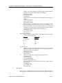
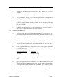
PIPE BAND AND LETTER SIZE:
A.
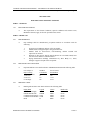
Pipe band and letter sizes shall conform to ASHRAE standards and the following table:
O.D. of Pipe or
Pipe Covering
1-1/4" and smaller
1-1/2" to 2"
2-1/2" to 5"
6" and larger
2.03
Width of
Color Band
8"
8"
12"
24"
Size of Letters
and Numbers
1/2"
3/4"
1-1/4"
2-1/2"
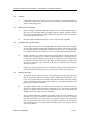
IDENTIFICATION:
A.
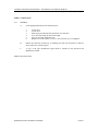
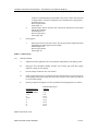
Band legend and letter color shall conform to the following table:
Piping Band
Chilled Water Supply
Chilled Water Return
Condenser Water Supply
Condenser Water Return
Drain
IDENTIFICATION OF PIPING SYSTEMS
Legend
CHWS
CHWR
CWS
CWR
D
Letters
White
White
White
White
Black
Band Color
Green
Green
Green
Green
Green
15020-1
CAMPUS CHILLED WATER PIPING – UNIVERSITY OF NORTH GEORGIA
Spencer Bristol Engineering, Inc.
PART 3 - EXECUTION
3.01
GENERAL:
A.
Locate piping identification at the following areas:
1.
2.
3.
4.
5.
6.
At each riser.
At each valve.
Where pipes pass through walls and floors (one each side).
At or near each change in direction or height.
Every 40 feet along continuous runs.
Within 4 feet of the entrance or exit to a vessel, tank or piece of equipment.
B.
Indicate flow direction with arrows of matching style and color and placed so that the
arrow points away from the legend.
C.
A copy of the pipe identification legend shall be included in the Operation and
Maintenance manual.
END OF SECTION 15020
IDENTIFICATION OF PIPING SYSTEMS
15020-2
CAMPUS CHILLED WATER PIPING – UNIVERSITY OF NORTH GEORGIA
Spencer Bristol Engineering, Inc.
SECTION 15030
TRENCH EXCAVATION AND BACKFILL
PART 1 - GENERAL
1.01
RELATED DOCUMENTS:
A.
1.02
The requirements of the General Conditions, Special Conditions and Section 15010,
Mechanical General, apply to all work specified in this section.
DESCRIPTION:
A.
All work associated with the installation of underground piping shall conform to the
requirements of this section including but not necessarily limited to:
1.
2.
3.
4.
5.
6.
1.03
Trench excavation.
Sheeting and/or shoring.
Dewatering.
Pipe installation.
Backfill.
Compaction.
QUALITY ASSURANCE:
A.
Work shall be performed by qualified firms having at least three years of successful
trench excavation and backfill experience.
PART 2 - PRODUCTS
2.01
MATERIALS:
A.
Granular bedding and select backfill materials shall be durable gravel, crushed stone or
bankrun gravel meeting the graduation requirements of the State Department of
Transportation Specifications.
B.
Common Backfill:
1.
2.
Common backfill shall consist of mineral soil free of organic material, loam,
wood, trash, snow, ice, frozen soil and other objectionable material which may
be compressible or which cannot be compacted properly. Common backfill shall
not contain stones larger 2 inches in any dimension, nor broken concrete,
masonry, rubble or other similar materials. It shall have physical properties such
that it can be readily deposited and compacted during backfilling.
Common backfill material falling within the above specifications and
encountered during the excavation may be stored in segregated stockpiles for reuse. All materials which, in the opinion of the Architect, is not suitable for reuse shall be disposed of as specified herein for disposal of unsuitable materials.
TRENCH EXCAVATION AND BACKFILL
15030-1
CAMPUS CHILLED WATER PIPING – UNIVERSITY OF NORTH GEORGIA
Spencer Bristol Engineering, Inc.
PART 3 - EXECUTION
3.01
COORDINATION:
A.
3.02
3.03
DISPOSAL OF MATERIALS:
A.
Stack excavated material without excessive surcharge near the trench bank. Avoid
inconvenience to traffic as much as possible. Segregate excavated material for use in
backfilling as specified below.
B.
Stockpile surplus excavated material which is suitable for use in backfilling. Dispose of
unsatisfactory surplus material.
C.
Remove no excavated material from the site or disposed of except as directed by the
Engineer.
D.
Should conditions make it impracticable or unsafe to stack material adjacent to the
trench, haul and store the material. When required, rehandle it and use in backfilling the
trench. Perform this at no additional cost to the Contract.
SHEETING AND BRACING:
A.
3.04
The work covered by this section is defined to include whatever excavating and
backfilling is necessary to install the underground mechanical work. Coordinate the work
with other excavating and backfilling operations in the same area, including dewatering
and other temporary facilities. Coordinate the work with other work in the same area
including other underground services (whether existing or new), landscape development,
paving, foundations and floor slabs on grade. Coordinate with anticipated weather
conditions and provide temporary facilities needed for protection and proper performance
of excavating and backfilling operations.
Furnish, put in place and maintain sheeting and bracing required to support the sides of
the excavation and prevent loss of ground which could damage or delay the work or
endanger adjacent structures. Take care to prevent voids outside of the sheeting, however
if voids are formed, they shall be immediately filled and rammed.
DRAINAGE:
A.
Furnish all materials and equipment and perform all incidental work required to install
and maintain the drainage system that is proposed for handling ground water or surface
water encountered. Do not begin construction until the Engineer is assured that the
proposed method will be satisfactory. Excavations shall have a stable subgrade. Alter the
drainage methods if, in the opinion of the Engineer, the trench bottom is unsatisfactory.
B.
Provide pumping equipment and devices to properly remove and dispose of all water
entering the trench and excavation for structures. Maintain the grade acceptably dry until
structures to be built therein are completed. Perform all drainage without damage to the
trench, pavements, pipes or other utilities. Dispose of water in a manner acceptable to the
Engineer and to the local authority having jurisdiction.
TRENCH EXCAVATION AND BACKFILL
15030-2
CAMPUS CHILLED WATER PIPING – UNIVERSITY OF NORTH GEORGIA
Spencer Bristol Engineering, Inc.
3.05
3.06
C.
Grade the tops of trenches as required to prevent surface water from flowing into the
trenches.
D.
Do not lay pipes in water nor allow them to become submerged prior to backfilling.
TRENCH EXCAVATION:
A.
Make excavations to the depth as required by the drawings and in such a manner and to
such minimum widths as will provide suitable room for laying the pipe within the trench,
for bracing and shoring, and for pumping and drainage facilities, and render the bottoms
of the excavations firm and dry at all times.
B.
The sides of the trenches shall be vertical to a point not less than 12 inches above the top
of the pipe.
C.
The trenches may be excavated by machinery to, or just below the designated subgrade
provided that the material remaining in the bottom of the trench is no more than slightly
disturbed.
D.
Where the pipes are to be laid directly on the trench bottom, do not excavate the lower
part of the trench to grade by machinery. Excavate the last of the material to be excavated
manually and do so in such a manner that it will provide a flat bottom and true to grade,
so that the pipe can be evenly supported on undisturbed material. Make bell holes as
required to accommodate the installation of the pipe.
E.
Where bedding material is to be provided, excavate the bottom of the trench to a depth of
4 inches below the bottom of the pipe for the bedding material.
F.
Remove rock, when encountered, to a minimum of 8 inches clearance around the bottom
and sides of the pipe being laid.
PIPE BEDDING:
A.
Furnish and install pipe on the type of bedding indicated on the drawings and as specified
herein. Regardless of the type of bedding used, provide holes in the trench to receive the
pipe bells. The holes excavated shall be sufficient to relieve the pipe bells of all loads and
to provide support over the total length of the pipe barrel. Carefully prepare the bedding
so that the pipe, after installation, will be true to line and grade.
B.
Pipe Bedding Classifications:
1.
2.
Class D-1 Bedding. For Class D-1 bedding, hand shape the trench bottom to
provide holes to receive the pipe bells. The holes excavated shall be sufficient to
relieve the pipe bells of all loads and shall permit the trench bottom to provide
support along the entire length of the pipe barrel. Grade the bottom of the trench
so that the pipe will be true to line and grade. Class D-1 pipe bedding may be
used for pressure piping only.
Class C-1 Bedding. For Class C-1 bedding, compact granular bedding material
in the trench bottom to provide a minimum thickness of 4 inches below the
bottom of the pipe. Then shape the bedding material by hand to the contour of
the pipe barrel. Provide bell holes for the pipe bells to ensure that loads are not
TRENCH EXCAVATION AND BACKFILL
15030-3
CAMPUS CHILLED WATER PIPING – UNIVERSITY OF NORTH GEORGIA
Spencer Bristol Engineering, Inc.
3.
4.
5.
6.
C.
3.07
transmitted to the pipe bells. Use sufficient bedd roing material to provide a
depth of 1/6 of the pipe outside diameter. Where the trench bottom has been
over-excavated below the required grade, Class C-1 bedding shall be used.
Class C-2 Bedding. For Class C-2 bedding, the bottom of the trench shall be
undisturbed and shall be hand shaped to provide continuous contoured support
along the entire length of the pipe, for a minimum of 50% of the pipe barrel.
Provide bell holes at all pipe bells to ensure that loads are not transmitted to the
pipe bells.
Class B-1 Bedding. For Class B-1 bedding, compact granular bedding material
in the trench bottom to provide a minimum thickness of 4 inches below the
bottom of the pipe. Then shape the bedding material by hand to the contour of
the pipe barrel. Provide bell holes for the pipe bells to ensure that no loads are
transmitted to the pipe bells. Use sufficient bedding material to provide a depth
of material equal to the springline of the pipe. Where rock has been excavated
from the trench bottom, Class B-1 bedding shall be used, and a minimum
bedding thickness of 8 inches shall be provided.
Class B-2 Bedding. For Class B-2 bedding, utilize sand as the bedding material,
compacted in the trench bottom to provide a minimum thickness of 4 inches
below the bottom of the pipe. Then shape the bedding material by hand to the
contour of the pipe barrel. Provide bell holes for the pipe bells to ensure that no
loads are transmitted to the pipe bells. Use sufficient bedding material to provide
a depth of material 12 inches above the top of the pipe.
Class A-1 Bedding. For Class A-1 bedding, compact granular bedding material
in the trench bottom to provide a minimum thickness of 4 inches below the
bottom of the pipe. Then shape the bedding material by hand to the contour of
the pipe barrel. Provide bell holes for the pipe bells to ensure that no loads are
transmitted to the pipe bells. Use sufficient bedding material to provide a depth
of material equal to the springline of the pipe. After the bedding material has
been compacted to the springline of the pipe, pour a lean concrete mix, 2000 psi
minimum, the full width of the trench, to a depth of 6 inches above the top of the
pipe. Concrete shall be cured and protected from injury due to construction and
weather prior to subsequent backfilling operations.
As soon as possible after the pipe has been brought to grade, aligned and jointed, shovel
additional bedding or backfill material, depending upon the class of bedding, uniformly
and simultaneously on each side of the pipe up to the pipe centerline. Thoroughly hand
tamp on both sides and under the pipe. Maintain the pipe in proper position and
alignment during subsequent pipe jointing, embedment and backfilling operations.
PIPE INSTALLATION:
A.
Lay all piping accurately to line and grade by the use of lasers, batter boards (spaced not
more than 25 feet apart), or plumb lines. Have three consecutive batter boards in place at
all times when installing the pipe. When necessary, deflect the pipe at the joints.
Deflection shall not exceed the manufacturer's recommendations.
B.
Prior to making joints, clean and dry all surfaces of the pipe joint and jointing materials.
Use lubricants, primer and adhesives as recommended by the pipe or joint manufacturer.
Then make joints in an approved workmanlike manner to obtain a water-tight joint. Keep
trenches free of water during bedding, pipe laying, jointing and backfilling.
TRENCH EXCAVATION AND BACKFILL
15030-4
CAMPUS CHILLED WATER PIPING – UNIVERSITY OF NORTH GEORGIA
Spencer Bristol Engineering, Inc.
3.08
3.09
BACKFILLING:
A.
As soon as practicable after the pipe has been laid, jointed and tested, begin backfilling
and expedite completion.
B.
After the required bedding has been placed, or after the pipe has been properly bedded on
a shaped trench bottom, place backfill material, free from stones and other foreign
material to a depth of 12 inches over the top of the pipe. Place backfill in 12 inch lifts and
thoroughly compact by hand tamping as placed.
C.
Pack full any remaining spaces or voids between the pipe and the sides of the trench by
hand shovel with selected earth, free from stones having a diameter greater than 2 inches,
and thoroughly compact with a tamper, as placed up to a level of 12 inches above the top
of the pipe.
D.
Carry the backfilling up evenly on both sides of the pipe with continuous tamping.
E.
Place backfill in 8 inch to 12 inch lifts to obtain the compaction desired.
F.
Fill and thoroughly compact the remainder of the trench above the compacted backfill by
rolling or tamping. All trench compaction shall be at least 95% of its maximum dry
density as determined by the Standard Proctor Test, ASTM D-698.
RESTORATION OF DISTURBED SURFACES:
A.
3.10
Where it is necessary to remove and replace landscape work, pavement, sidewalks,
flooring and similar exposed finished work, engage the original installer to install the
replacement work, except where the work existed prior to the work of this contract. In
this instance, engage only experienced and expert firms and tradespersons to replace the
work.
CLEANUP:
A.
Promptly remove all discarded or unused materials, trash and debris and dispose of it off
the Owner's property. Dispose of excess excavated material as directed by the Engineer.
END OF SECTION 15030
TRENCH EXCAVATION AND BACKFILL
15030-5
CAMPUS CHILLED WATER PIPING – UNIVERSITY OF NORTH GEORGIA
Spencer Bristol Engineering, Inc.
SECTION 15080
TEST AND BALANCE
PART 1 - GENERAL
1.01
RELATED DOCUMENTS:
A.
1.02
The requirements of the General Conditions, Special Conditions and Section 15010,
Mechanical General, apply to all work specified in this section.
SCOPE OF WORK:
A.
Procure the services of an independent Test and Balance agency that is independent of
any contractor or manufacturer to perform the testing and balancing and to prepare
reports to the Engineer. The Test and Balance agency shall be a certified member of the
Associated Air Balance Council (AABC) or the National Environmental Balancing
Bureau (NEBB).
B.
Perform testing and balancing in accordance with the 6th. edition of the AABC National
Standards (2002) for Total System Balance, and in accordance with the scope of work
defined herein.
C.
The Test and Balance agency, as part of its contract, shall act as an authorized inspection
agency, responsible to the Owner and shall, during the test and balance, list all systems
that require correction or that have not been installed in accordance with the drawings
and specifications.
D.
A single agency shall be responsible for all phases of testing and balancing.
E.
Do not begin testing and balancing until all systems have been completed and are in full
working order. Put all mechanical equipment into full operation and continue the
operation of same during each working day of testing and balancing.
F.
Upon the completion of the test and balance work the agency shall compile the test data
and submit four copies of the complete report to the Engineer for his evaluation and
approval.
PART 2 - PRODUCTS
2.01
MATERIALS:
A.
Provide all required instrumentation, equipment, tools, devices and utility services to
perform the operations as specified herein.
B.
Calibrate instruments used for testing and balancing of systems within six months
preceding the tests and check them for accuracy prior to start of work.
C.
Instruments shall be of a type normally recognized as adequate and accurate for the test
contemplated. List the types of instruments, including manufacturer, serial number and
latest calibration date as a part of the submitted test data.
TEST AND BALANCE
15080-1
CAMPUS CHILLED WATER PIPING – UNIVERSITY OF NORTH GEORGIA
Spencer Bristol Engineering, Inc.
2.02
PATCHING MATERIALS:
A.
Unless indicated otherwise, use same products as used in the work for patching holes in
insulation which have been cut or drilled for test purposes, including access for test
instruments, attaching jigs and similar purposes.
PART 3 - EXECUTION
3.01
REQUIRED DOCUMENTS:
A.
Provide the following, in a timely fashion, to the Test and Balance agency:
1.
2.
3.
3.02
COOPERATION:
A.
3.03
3.04
A.
Make a complete system operating test for a period of eight hours with controls set in
their various positions to ensure proper operation under the design conditions. Make all
tests and final adjustments to the complete satisfaction of the Owner and the Engineer.
B.
Schedule the operating test four weeks prior to scheduled completion date.
CONTROL PERFORMANCE CHECK:
The results produced by the operation of automatic controls shall be checked by the Test
and Balance agency. List and report controls requiring adjustment. The agency shall be
responsible only for final settings.
SETTINGS:
A.
3.06
Cooperate fully with the Test and Balance agency and provide them with completely
operable systems, the right to adjust the systems and access to the system components.
OPERATING TEST:
A.
3.05
Contract drawings (complete set).
Applicable specifications (Division 15 and 16 as a minimum).
Related addenda, change orders, reviewed shop drawings, reviewed equipment
manufacturer's submittal data and reviewed temperature control drawings.
Permanently mark the settings of all valves and other adjustment devices in a manner that
will allow the settings to be restored. If a balancing device is provided with a memory
stop it shall be set and locked.
WATER BALANCING PROCEDURE:
A.
Prepare the hydronic systems for balancing in the following manner:
1.
2.
3.
TEST AND BALANCE
Open all valves to full open position. Close coil bypass valves. Set mixing
valves to full coil flow.
Check pump rotation.
Check the expansion tank to determine it is not air bound and that the system is
properly charged.
15080-2
CAMPUS CHILLED WATER PIPING – UNIVERSITY OF NORTH GEORGIA
Spencer Bristol Engineering, Inc.
4.
5.
B.
After completion of the preliminary work described above, follow the following
balancing procedure:
1.
2.
3.
3.07
Check all air vents at the high points of the system to determine that all are
installed and operating freely.
Set temperature controls to full cooling for balancing chilled water coils.
Set pumps to the specified gallons per minute delivery.
Upon completion of flow readings and adjustments at coils re-check settings at
the pumps and readjust if necessary.
Balance each end device to its proportionate share of the pump total GPM based
on the ratio of the pump total GPM as compared to the sum of GPM for all end
devices.
WATER BALANCING REQUIREMENTS:
A.
Centrifugal chiller: Adjust and service the refrigeration machine in accordance with the
manufacturer's recommendations. Furnish data, tabulating the following:
1.
2.
3.
4.
5.
B.
Cooling tower: Adjust belts, gears, sheaves and alignment. Flush and refill the tower
basin and condenser water piping until water runs clear. Furnish data tabulating the
following:
1.
2.
3.
4.
5.
6.
7.
C.
Quantity of discharge air in CFM.
Quantity of water circulated through tower.
Temperature of entering and leaving water.
Capacity of tower in BTUH as calculated from flow and temperature difference.
RPM of fan and motor.
Ampere input of motor (one reading for each phase leg on 3 phase motors).
Ambient dry bulb and wet bulb temperatures of air entering cooling tower
during tests
Chilled water coils: Clean exterior surface of coil tubes and fins. Flush interior of tubes
with water until water runs clear. Straighten fins. Furnish data tabulating the following:
1.
2.
3.
4.
5.
6.
D.
Suction and condensing temperatures and pressures.
Temperatures of entering and leaving chilled and condenser water.
Voltage and ampere input of motors under full load (one for each phase leg).
Capacity of machine in BTUH as calculated from flow & temperature drop.
Quantity of chilled and condenser water circulated through machine in GPM.
Entering and leaving water temperature.
Quantity of air in cfm.
Face velocity in fpm.
Dry and wet bulb air temperature entering and leaving coil.
Capacity of coil in BTUH.
Quantity of water circulated through coil in GPM.
Pumps: Adjust and service pumps in accordance
recommendations. Furnish data tabulating the following:
TEST AND BALANCE
with
the
manufacturer's
15080-3
CAMPUS CHILLED WATER PIPING – UNIVERSITY OF NORTH GEORGIA
Spencer Bristol Engineering, Inc.
1.
2.
3.
4.
5.
Quantity of water circulated by in GPM.
Suction and discharge pressures across pump in PSIG.
Voltage and ampere input of motor (one reading for each phase leg on three
phase motors).
Percent efficiency of pump.
Horizontal, vertical and angular misalignment of pump and driver after two
hours operation and after remaining idle overnight.
END OF SECTION 15080
TEST AND BALANCE
15080-4
CAMPUS CHILLED WATER PIPING – UNIVERSITY OF NORTH GEORGIA
Spencer Bristol Engineering, Inc.
SECTION 15100
PIPE HANGERS AND SUPPORTS
PART 1 - GENERAL
1.01
RELATED DOCUMENTS:
A.
1.02
1.03
The requirements of the General Conditions, Special Conditions and Section 15010,
Mechanical General, apply to all work specified in this section.
GENERAL REQUIREMENTS:
A.
Furnish hangers to support the required loads. Where necessary, design supports to
permit movement due to expansion and contraction. Where the drawings show details of
supports and anchors, conform to details shown. Where details are not shown, conform to
general requirements specified herein.
B.
Do not use "C" clamps to support pipe hangers from the structure.
C.
Do not pierce waterproofing or insulation vapor barrier with supports or support bolts.
D.
All ferrous metal hangers, supports and rods shall be cadmium plated or galvanized.
QUALITY ASSURANCE:
A.
All hangers, support, anchors and guides shall be in accordance with the American
National Standard Code for Pressure Piping, ANSI/B31.1 with Addenda 31.1 OA-69 and
Federal Specification WW-H-17.
B.
Provide an adequate piping suspension system using standard commercially available
pipe hangers and accessories.
C.
Hang horizontal suspended pipes using adjustable pipe hangers with bolted hinged loops
or turnbuckles. Do not use chains, wire, perforated strap iron, flat steel straps or similar
construction.
PART 2 - PRODUCTS
2.01
CHILLED AND CONDENSER WATER SERVICE:
A.
Suspended insulated pipe:
1.
Upper attachments:
a.
Support piping in concrete construction with cadmium plated,
malleable iron expansion case anchor.
Grinnell Figure 117
B-Line Series LA
Elcen Figure 212
b.
Where hangers are required between structural concrete beams provide
side beam brackets attached to the upper 1/3 of the beam, and all
PIPE HANGERS AND SUPPORTS
15100-1
CAMPUS CHILLED WATER PIPING – UNIVERSITY OF NORTH GEORGIA
Spencer Bristol Engineering, Inc.
2.
3.
B.
auxiliary steel for the installation of the pipe hangers. Supports shall be
designed in accordance with the AISC Steel Handbook.
Grinnell Figure 202
B-Line Figure B3062
Elcen Figure 27
c.
Support piping in steel construction with adjustable beam clamps and
tie rods.
Grinnell Figure 218
B-Line Figure B3054
Elcen Figure 95 and 76
d.
Where hangers are required between structural steel beams or joists
provide a welded steel bracket sized to meet the constraints of the
structural installation. The bracket shall be attached with a continuous
weld between the support and the structural member. Supports shall be
designed in accordance with the AISC Steel Handbook.
Grinnell Figure 195
B-Line Figure B3066
Elcen Figure 57
Intermediate attachments:
a.
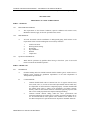
Supports for horizontal piping shall be all threaded carbon steel, ASTM
A-107 of the following sizes:
Pipe Size
Hanger Rod
Diameter
2" and smaller
3/8"
2-1/2"
1/2"
3"
1/2"
4"
5/8"
6"
7/8"
8"
1"
Pipe attachments:
a.
Hangers for horizontal piping shall be clevis type with vertical
adjustment. Hangers for insulated pipes shall be selected to bear on a
pipe shield outside of the insulation.
Grinnell Figure 260
B-Line Figure B3100
Elcen Figure 12
b.
Hangers for multiple horizontal piping shall be trapeze type.
Grinnell Figure 46
B-Line Figure B22
Unistrut Model P3200
Michigan Hanger Figure 380
c.
Provide an insulation protection shield between the hangers and the
pipe insulation.
Grinnell Figure 167
B-Line Figure B3151
Elcen Figure 400
Wall supports:
1.
Where piping is run adjacent to walls or steel columns welded steel brackets
may be used. The bracket shall either be bolted to the wall with a back plate or
PIPE HANGERS AND SUPPORTS
15100-2
CAMPUS CHILLED WATER PIPING – UNIVERSITY OF NORTH GEORGIA
Spencer Bristol Engineering, Inc.
2.
C.
welded to a mounting flange then attached to the wall or column. The back plate
or flange shall be of such size and thickness as to distribute the weight properly.
Grinnell Figure 195
B-Line Figure B3066
Elcen Figure 57
Insulated pipes shall be provided with a protection shield between the hanger
and the pipe insulation.
Grinnell Figure 167
B-Line Figure B3151
Elcen Figure 400
Floor supports:
1.
Where pipe runs are located next to the floor the pipe shall be supported with an
adjustable pipe saddle support and floor flange.
Grinnell Figure 264
B-Line Figure B3092
Elcen Figure 50
PART 3 - EXECUTION
3.01
INSTALLATION:
A.
Support horizontal equipment such as air separators independently of the piping system.
B.
Hang pipe from substantial building structure. Do not hang pipe from other piping,
ductwork, ceilings or steel decking.
C.
Provide a hanger within one foot of each elbow.
D.
Isolate copper tubing from steel supports, anchors and metal studs to prevent electrolysis.
Isolate piping with neoprene pads, sheet lead strips or plastic inserts. Duct tape shall not
be used to isolate piping.
E.
Spacing of hangers and supports for above-ground horizontal piping shall be as follows:
Nominal Pipe Size
Steel pipe
1-1/4" and smaller
1-1/2"
2"
2-1/2"
3"
4"
6"
8"
Maximum Spacing of
Supports
7'-0"
9'-0"
10'-0"
11'-0"
12'-0"
14'-0"
17'-0"
20'-0"
END OF SECTION 15100
PIPE HANGERS AND SUPPORTS
15100-3
CAMPUS CHILLED WATER PIPING – UNIVERSITY OF NORTH GEORGIA
Spencer Bristol Engineering, Inc.
SECTION 15130
VALVES
PART 1 - GENERAL
1.01
RELATED DOCUMENTS:
A.
1.02
1.03
The requirements of the General Conditions, Special Conditions and Section 15010,
Mechanical General, apply to all work specified in this section.
QUALITY ASSURANCE:
A.
Codes and regulations referred to herein are minimum standards. Where the requirements
of these specifications or the drawings exceed those of the codes and regulations, the
drawings and specifications shall govern.
B.
All valves shall be designed and manufactured with back-seating features to allow them
to be re-packed under pressure when in full open position.
C.
Valve marking and identification shall conform to the Manufacturer's Standardization
Society for Valves, Fittings, Flanges and Unions, MSS Publication SP-25, and shall have
the name or trademark of the manufacturer and working pressure cast or stamped on the
valve body and the manufacturer's figure number securely attached to the stem.
D.
Provide valves of one manufacturer for each trade application wherever practical to
achieve maximum uniformity and to facilitate maintenance.
E.
Figure numbers of various manufacturers are designated as conforming to these
specifications. Valves of like characteristics may be furnished provided they meet or
exceed these specifications in every respect.
GENERAL:
A.
All valves requiring packing shall be designed and constructed to allow re-packing under
pressure when wide open. Deep stuffing box and packing nut shall be provided to ensure
firm thread attachment when fully packed.
B.
All valve hand-wheels shall be non-slip, malleable or modular iron unless indicated
otherwise under the individual type valve specification.
C.
Non-slam check valves shall be installed at all pumps. Swing-check and lift-check valves
are not acceptable.
D.
All valves installed in horizontal piping shall have the stems at or above the centerline of
the pipe. Valve hand-wheels shall be oriented to provide maximum accessibility.
VALVES
15130-1
CAMPUS CHILLED WATER PIPING – UNIVERSITY OF NORTH GEORGIA
Spencer Bristol Engineering, Inc.
PART 2 - PRODUCTS
2.01
CHILLED AND CONDENSER WATER SERVICE:
A.
Globe valves - 2" and smaller: Class 125 - 200 lb WOG, body and screw-in bonnet of
ASTM B-62 cast bronze composition, threaded ends, tapered renewable disc/seat closure,
copper silicon alloy stem, brass packing gland with hexagonal head, Teflon-impregnated
packing and non-slip malleable hand-wheel.
Stockham B-16
Powell 650
Milwaukee 502
B.
Globe valves - 2-1/2" and larger: Class 125 - 200 lb WOG iron body, bronze mounted
(IBBM) with body and bolted bonnet conforming to ASTM A-126 Class B cast iron,
regrindable bronze seats, renewable solid disc, flanged ends, with Teflon-impregnated
packing and two-piece packing gland assembly.
Stockham G-512
Powell 241
Milwaukee F-2981-M
C.
Butterfly valves - 2-1/2" and larger: Lug-body type, 200 lb CWP conforming to ASTM
A-126 Class B cast iron drilled and tapped to ANSI 125-150 flange standard, field
replaceable Buna-N sleeve, with 316 type stainless steel stem, Buna-N O-ring, lever
handles with memory stops. Sizes 8" and larger shall have gear operators with
handwheels, disc position indicators and memory stops. Any butterfly valve used as a
balancing valve shall have memory stops and a means for measuring pressure drop across
the valve such as Pete's plugs. Butterfly valves shall be rated for dead-end service.
Lever Operated up to 5"
Stockham LD-712
Centerline LT
Grinnell LC-8281-3
Milwaukee Series CL224B
D.
Gear Operated 6" and Over
Stockham LD-722
Centerline LT w/gear
Grinnell LC-8282-3
Milwaukee CL 324B
Check valves - 2" and smaller: Class 125 - 200 lb WOG, threaded ends, body and caps
shall be of ASTM B-26 cast bronze composition, integral and renewable seat, swing type
renewable and regrindable disc. Cap collar shall not extend past the body neck and have
wide flat face for wrench removal.
Stockham B-319
Powell 578
Milwaukee 509
E.
Check valves - 2-1/2" and larger: Class 125 - 200 lb WOG iron body, bronze mounted,
flanged ends, globe type silent check valves and stainless steel spring. Valves shall be
designed to completely close with a 1/2 psi positive discharge head.
Muessco 105 AP
Apco 600-636
VALVES
15130-2
CAMPUS CHILLED WATER PIPING – UNIVERSITY OF NORTH GEORGIA
Spencer Bristol Engineering, Inc.
Milwaukee 1800 Series
F.
Ball valves - 2" and smaller: 720 lb CWP, ASTM B-16 brass body composition, threaded
ends, replaceable reinforced Teflon seats. Full port opening in type 316 stainless steel
ball, stainless steel stem, reinforced Teflon seal and thrust washer and cadmium plated
steel nut and handle.
Stockham S-217 BR-R-T
G.
Drain valves: Threaded end, bronze body renewable composition disc, wheel handle, 3/4
NPT inlet, 3/4" house outlet.
Watts Regulator BD-1
Woodford 24
2.02
DOMESTIC COLD WATER SERVICE:
A.
Gate valves - 2" and smaller: Class 125 - 200 lb WOG and shall have body and threaded
bonnet of ASTM B-62 cast bronze composition, solid wedge disc, copper-silicon alloy
stem, brass packing gland, rising stem, solder ends, Teflon-impregnated packing and
malleable iron hand-wheel.
Stockham B-108
Powell 1821
Milwaukee 149
B.
Ball valves - 2" and smaller: 600 lb CWP, have cast brass body, replaceable reinforced
Teflon seat, conventional port, blowout proof stem, chrome-plated brass ball, solder ends
with extended solder cups. Provide stem extension to ensure handle clears insulation
where provided on insulated pipes.
Stockham S-216-BR-R-T
Apollo 70-200
Milwaukee "Butterball" BB2-350
C.
Globe valves - 2" and smaller: Class 125 - 200 lb WOG, body and union bonnet of
ASTM B-62 cast bronze composition, solder ends, composition disc, copper-silicon alloy
stem, brass packing gland, Teflon-impregnated packing and malleable iron hand-wheel.
Stockham B-14T
Powell 1823
D.
Pressure reducing valves - 2" and smaller: Bronze body, screwed ends, renewable seat
and disc, high temperature diaphragm for hot or cold water service, Y type strainer, water
tight cage assembly, adjustable outlet pressure.
Watts Regulator 223-SB
Wilkins Regulator 500-YS-BR
A.W. Cash E-55 Series
Mueller H-93000 Series
VALVES
15130-3
CAMPUS CHILLED WATER PIPING – UNIVERSITY OF NORTH GEORGIA
Spencer Bristol Engineering, Inc.
E.
Backflow preventers: Reduced pressure principle backflow preventers consisting of
assembly including shutoff valves and strainer at the inlet. Backflow preventers shall
include test cocks, air-gap drain funnel and pressure differential relief valve located
between two positive seating check valves. Backflow preventers shall conform to ASSE
Standard 1013.
Watts Regulator 909
Hersey Products FRP-11
Wilkins 575-RP
Clayton RP-1
PART 3 - EXECUTION
3.01
GENERAL:
A.
Automatic air vents shall be installed with gate or ball valves.
B.
Provide gate, globe and check valves throughout the piping systems where shown and
where necessary to properly regulate and control the systems. Valves shall be the full size
of the lines in which they are installed and shall be designed for low pressure drop.
END OF SECTION 15130
VALVES
15130-4
CAMPUS CHILLED WATER PIPING – UNIVERSITY OF NORTH GEORGIA
Spencer Bristol Engineering, Inc.
SECTION 15140
CENTRIFUGAL PUMPS
PART 1 - GENERAL
1.01
RELATED DOCUMENTS:
A.
1.02
The requirements of the General Conditions, Special Conditions and Section 15010,
Mechanical General, apply to all work specified in this section.
QUALITY ASSURANCE:
A.
Furnish pumps and install as indicated and scheduled on the drawings. Provide all
accessories, controls and wiring.
B.
Codes and regulations referred to are minimum standards. Where the requirements of
these specifications or the drawings exceed those of the codes and regulations, the
drawings and specifications shall govern.
C.
Centrifugal pumps manufactured by Allis-Chalmers, Aurora, Peerless, Patterson,
Armstrong or Bell and Gossett will be acceptable.
PART 2 - PRODUCTS
2.01
BASE MOUNTED END SUCTION PUMPS:
A.
Furnish and install bronze fitted, single stage, end suction, double ball bearing, flexible
coupled, frame mounted centrifugal pumps.
B.
For chilled and condenser water service pumps shall be designed for 175 psi at 225
degrees F working pressure. F. Pump flanges shall be drilled and tapped for gauge
connections.
C.
Each pump shall be mounted on a steel drip rim base and connected through a heavy duty
flexible coupling to a ball bearing, drip proof electric motor. Coupling shall be protected
by a formed steel coupling guard. Drip rim shall be tapped for drain connection and piped
to a floor drain.
D.
Pump casing shall be of a closed-grained cast iron, back pull-out design so that the
removal of the rotating parts can be accomplished without disturbing the piping
connections. Impeller shall be bronze with bronze wear rings. Shaft shall be steel with
bronze sleeve. Seals shall be of the mechanical type and capable of operating at 250
degrees F.
E.
Bearings shall be the ball type, grease lubricated with a 200,000 hours B-10 life.
F.
Pump motor shall have the capacity to prevent overloading with the pump operating at
any point on the curve, up to a minimum of 125% of the specified GPM. Shut-off head
shall be a minimum of 120% of the operating head.
CENTRIFUGAL PUMPS
15140-1
CAMPUS CHILLED WATER PIPING – UNIVERSITY OF NORTH GEORGIA
Spencer Bristol Engineering, Inc.
2.02
G.
Align the pump and motor according to the standards of the Hydraulic Institute after
grouting the base to the concrete pad and connecting the piping. Verify pump and motor
alignment by the manufacturer. Submit a written statement to the Engineer verifying
completion of alignment.
H.
Furnish an extra set of mechanical seals for each pump and turn over to the Owner.
CLOSE-COUPLED IN-LINE PUMPS:
A.
Furnish and install bronze fitted, single suction, replaceable sleeve, close-coupled, in-line
centrifugal pumps. Pumps shall be designed for a maximum water working pressure of
175 psi and a maximum temperature of 250 degrees F.
B.
Pumps shall be close-coupled with standard solid shaft ball bearing motors. Casing shall
be close grained cast iron of the back pull-out design. Impeller shall be one piece bronze
with replaceable bronze wear ring.
C.
The motor shall be equipped with a replaceable bronze sleeve installed between
mechanical seals.
D.
Motor bearings shall be grease lubricated and sized for a maximum of 100,000 hours B10 life. Pump motor shall have the capacity to prevent overloading with the pump
operating at any point on the curve, up to 125% of the specified GPM.
E.
Furnish an extra set of mechanical seals for each pump and turn over to the Owner.
PART 3 - EXECUTION
3.01
INSTALLATION:
A.
Install pumps as indicated and in strict accordance with the manufacturer's written
instructions.
B.
Furnish one spare set of seals for each pump, tagged to identify the pump served, and
deliver to the Owner.
C.
Align base mounted pumps after grouting to the base by a technician in the direct employ
of the pump manufacturer or by a factory authorized service organization. Submit a
written report to the Engineer certifying the equipment is installed in accordance with the
manufacturer's recommendations.
D.
Do not operate pumps until their respective systems are filled with liquid.
END OF SECTION 15140
CENTRIFUGAL PUMPS
15140-2
CAMPUS CHILLED WATER PIPING – UNIVERSITY OF NORTH GEORGIA
Spencer Bristol Engineering, Inc.
SECTION 15180
THERMAL INSULATION FOR MECHANICAL SYSTEMS
PART 1 - GENERAL
1.01
RELATED DOCUMENTS:
A.
1.02
1.03
The requirements of the General Conditions, Special Conditions and Section 15010,
Mechanical General, apply to all work specified in this section.
DESCRIPTION:
A.
All insulation products shall meet NFPA requirements for a Flame Spread Rating not to
exceed 25, a Smoke Developed Rating not to exceed 50 and a Fuel Contributed Rating
not to exceed 50.
B.
Do not use staples for securing insulation.
C.
Insulation and vapor barrier shall be continuous through wall and floor sleeves.
D.
Supports for insulated piping shall be outside the insulation. For pipe sizes 2-1/2 inch and
larger provide inserts and pipe shields at pipe hangers. For pipe sizes 2 inch and smaller
provide pipe shields only at pipe hangers. Inserts shall be foamglass or calcium silicate
insulation and shall be 2" longer than the pipe shields.
E.
Do not store insulation materials in the building until it is enclosed and dry. Do not install
wet insulation.
F.
Do not apply insulation products with self-sealing type lap jackets at ambient
temperatures below 40 degrees F.
G.
Paint ferrous metal piping installed outdoors above grade with one coat of rust inhibiting
primer before installing insulation.
QUALITY ASSURANCE:
A.
Codes and regulations referred to in these specifications are minimum standards, however
if the requirements of these specifications exceed those of the codes and regulations, the
specifications shall govern.
B.
Any methods of application of insulation products or finishes not specifically detailed
herein shall be applied in accordance with the insulation manufacturer's published
recommendations. Apply insulation by experienced workers regularly employed in this
type of work.
C.
Insulation products manufactured by Owens-Corning, Johns-Manville, CertainTeed,
Knauf or Armstrong will be acceptable.
D.
Adhesives, mastics and coatings manufactured by Benjamin Foster, Childers, InsulCoustic or Minnesota Mining and Manufacturing Co. (3M) will be acceptable.
THERMAL INSULATION FOR MECHANICAL SYSTEMS
15180-1
CAMPUS CHILLED WATER PIPING – UNIVERSITY OF NORTH GEORGIA
Spencer Bristol Engineering, Inc.
PART 2 - PRODUCTS
2.01
PRE-MOLDED GLASS FIBER PIPE INSULATION:
A.
2.02
Pipe insulation shall be 4 pcf density fibrous glass wool accurately molded to conform to
the outside diameter of the pipe. Insulation shall be the one piece snap-on or self-sealing
lap type with white all-service jacket and vapor barrier. Insulation shall be suitable for
use on hot or cold pipes with a temperature range of 35 to 400 degrees F. Thermal
conductivity shall not exceed 0.26 at 75 degrees F mean temperature.
PRE-MOLDED GLASS FIBER INSULATION THICKNESS IN INCHES:
Service
Plumbing systems
Domestic cold water
Cooling systems
Condenser water
2.03
2-1/2” to
3-1/3”
4” and
Over
1/2"
1/2"
---
---
1/2"
1"
1"
1-1/2"
Pre-molded pipe insulation shall be 8 pcf minimum density rigid cellular glass and vapor
barrier with a thermal conductivity not to exceed 0.25 at 75 degrees F mean temperature.
CELLULAR GLASS INSULATION THICKNESS IN INCHES:
Service
Cooling systems
Chilled water
2.05
1-1/4" to
2”
CELLULAR GLASS PIPE INSULATION:
A.
2.04
Up to
1"
Up to
1"
1-1/4" to
2"
2-1/2" to
3-1/2"
4" and
Over
1"
1-1/2"
2"
2"
FOAMED PLASTIC SHEET AND TUBING:
A.
Foamed plastic sheet and tubing shall have a minimum density of 4.5 pcf. Thermal
conductivity shall not exceed 0.28 at 75 degrees F mean temperature.
B.
Apply and secure insulation and seal all joints with Armaflex 520 adhesive so as to
maintain a continuous vapor barrier. On piping, do not split the insulation longitudinally
except at branch fittings where it cannot be avoided.
C.
Insulate the following with 1/2" thick foamed plastic tubing insulation:
1.
D.
Condensate drain piping.
Insulate the following with 3/4" thick foamed plastic tubing insulation:
1.
Refrigerant suction piping. Coat piping outside the building with two coats of
white, ultra-violet resistant Armaflex vinyl lacquer.
THERMAL INSULATION FOR MECHANICAL SYSTEMS
15180-2
CAMPUS CHILLED WATER PIPING – UNIVERSITY OF NORTH GEORGIA
Spencer Bristol Engineering, Inc.
E.
Insulate the following with 1" thick foamed plastic sheet or tubing:
1.
2.
3.
F.
2.06
2.07
A.
The treatment of pipe insulation jackets to impart flame spread and smoke developed
ratings shall be permanent. The use of water-soluble treatments is prohibited.
B.
Vapor barriers shall be installed on all pipe insulation which shall have a perm rating of
not more than 0.05 perms. Adhesives, coatings and mastics shall have a perm rating of
not less than 0.25 perms.
TAPE:
Whenever tape is used for sealing purposes, it shall be of the type and shall be applied as
recommended by the covering manufacturer.
INSULATING CEMENT:
A.
2.09
Insulate chilled water pump heads with 1-1/2" thick foamed plastic sheet adhered to a
removable 20 gauge aluminum casing.
ADHESIVES, MASTICS, COATINGS AND VAPOR BARRIERS:
A.
2.08
Chilled water strainers.
Chilled water access plates.
Chilled water couplings.
Insulating cement shall be Owens-Corning 110 mineral wool, Benjamin Foster, or 3M
All Purpose Cement. Where insulating cement is applied to pipe fittings in concealed
locations it shall be "one-coat" cement.
GLASS CLOTH JACKET:
A.
Glass cloth jacket on pipe insulation shall be open weave, standard weight.
PART 3 - EXECUTION
3.01
GENERAL:
A.
Clean all surfaces to be insulated of all loose scale, dirt, rust, oil and other foreign matter
and thoroughly dry before applying insulation.
B.
Perform pressure tests required by other sections before insulation is applied.
C.
Where existing insulation is damaged due to demolition or construction operations,
remove and replace it with new insulation to match the existing work or as specified
herein for new insulation.
D.
Insulate completely all metal surfaces of piping other than hangers.
E.
Insulation surface finishes shall present a tight, smooth appearance and the surface finish
shall be extended to protect all raw ends and edges of the insulation.
THERMAL INSULATION FOR MECHANICAL SYSTEMS
15180-3
CAMPUS CHILLED WATER PIPING – UNIVERSITY OF NORTH GEORGIA
Spencer Bristol Engineering, Inc.
3.02
3.03
3.04
INSULATION FOR PIPING:
A.
Insulate all valves including valve bonnets on chilled water piping, strainers, flanges and
fittings. Use pre-molded material where available.
B.
Install insulation materials with smooth and even surfaces, with jackets drawn tight and
cemented down smoothly at longitudinal seams and end laps. Do not use scrap pieces of
insulation where a full length of insulation will fit.
C.
Install insulation, jackets and coatings continuous through wall and floor openings and
through pipe sleeves.
D.
Insulate valves, strainers, fittings, and flanges with field fabricated, multiple mitered
segments of molded pipe insulation of the same thickness and material as the adjoining
pipe insulation. Secure segments with 20 gauge galvanized steel wire and apply a
smoothing coat of insulating cement. Use white fabric and mastic on all fittings exposed
to view such as in mechanical rooms.
E.
For foam plastic insulation, butt all joints together and seal with joint straps furnished
with the insulation. Secure all jacket laps with lap adhesive.
F.
Insulate all chilled water piping appurtenances such as thermometer wells, gauge cocks,
valve stems and the like with foamed plastic sheet or tubing. Seal all joints with flexible
joint sealer.
G.
On piping exposed outdoors above grade, oversize the insulation to allow for heat tape,
and do not apply insulation until the pipe has been painted and the heat tape applied.
Finish the insulation with standard weight glass cloth set in a 1/16" thick bed of vapor
barrier. After drying, apply a 1/16" coat of weatherproof vapor barrier similar to "SealKote". Protect insulation, including all fittings, with 0.024" thick corrugated aluminum,
overlapped at the seams a minimum of 2", arranged to shed water and secured with
aluminum bands spaced not more than 16" apart.
INSULATION FOR EQUIPMENT:
A.
Secure insulation to the equipment with insulation hangers with self locking washers,
copper wire or galvanized steel bands. Miter the insulation to ensure a tight fit. Seal all
joints with mineral wool insulating cement. Finish with standard weight glass cloth set
between two coats of 1/16" thick white mastic.
B.
Insulate the chilled water pump heads with a 20 gauge removable aluminum casing, lined
with 1-1/2" thick foamed plastic sheet, adhered to all inside surfaces of the casing.
Fabricate the casing in two sections, joined with galvanized steel bolts, nuts and washers
and arranged so that the casing may be removed and reinstalled without damaging the
insulation.
MISCELLANEOUS EQUIPMENT:
A.
Insulate bypass chemical feeders and associated piping the same as the piping system in
which they are installed.
THERMAL INSULATION FOR MECHANICAL SYSTEMS
15180-4
CAMPUS CHILLED WATER PIPING – UNIVERSITY OF NORTH GEORGIA
Spencer Bristol Engineering, Inc.
3.05
CLEANING:
A.
Prior to final acceptance, clean the finished surfaces of all exposed insulation of all stains
and blemishes. If necessary to obtain a new appearance, coat any discolored insulation
with off-white latex based semi-gloss paint or lagging adhesive.
END OF SECTION 15180
THERMAL INSULATION FOR MECHANICAL SYSTEMS
15180-5
CAMPUS CHILLED WATER PIPING – UNIVERSITY OF NORTH GEORGIA
Spencer Bristol Engineering, Inc.
SECTION 15200
VIBRATION ISOLATORS
PART 1 - GENERAL
1.01
RELATED DOCUMENTS:
A.
1.02
1.03
The requirements of the General Conditions, Special Conditions, and Section 15010,
Mechanical General, apply to all work specified in this section.
COORDINATION:
A.
All isolation devices and bases shall be the products of a single vibration manufacturer.
Submittal data shall include size, type, load and deflection of each isolator selected.
Submittal data shall also include clearly outlined procedures for setting and adjusting all
isolation devices.
B.
Coordinate the vibration isolation supports with the manufacturer of the equipment to be
isolated. Prior to submitting shop drawings to the Architect, the equipment manufacturer
shall review and approve the vibration isolator shop drawings in writing.
QUALITY ASSURANCE:
A.
Vibration isolation devices manufactured by Amber Booth, Consolidated Kinetics Corp.,
Korfund Dynamics Corp., Mason Industries, Inc., or Vibration Eliminator Co. will be
acceptable.
B.
Where a specific type of vibration isolation equipment is not shown on the drawings or
specified, furnish isolators as recommended by the isolation manufacturer, compatible
with the equipment arrangements shown.
PART 2 - PRODUCTS
2.01
PADS:
A.
Pads shall be the neoprene waffle type with identical rubber grids molded back to back.
The interconnections shall form suction pockets for gripping smooth steel as well as
rough surfaces regardless of how the pad is cut. The square waffle pattern shall be laid
out on 1/2" centers.
PART 3 - EXECUTION
3.01
GENERAL:
A.
Furnish waffle type pads under the chiller and cooling tower as indicated on the
drawings.
VIBRATION ISOLATORS
15200-1
CAMPUS CHILLED WATER PIPING – UNIVERSITY OF NORTH GEORGIA
Spencer Bristol Engineering, Inc.
3.02
INSTALLATION:
A.
Provide vibration isolators for the indicated mechanical equipment to prevent the
transmission of vibration and mechanically transmitted sound to the building structure.
Vibration isolators shall be selected by the isolator manufacturer in accordance with the
weight distribution of the actual equipment provided so as to produce a uniform
deflection.
B.
There shall be no direct contact of isolated piping or equipment with partitions, conduits,
floor slabs or walls.
END OF SECTION 15200
VIBRATION ISOLATORS
15200-2
CAMPUS CHILLED WATER PIPING – UNIVERSITY OF NORTH GEORGIA
Spencer Bristol Engineering, Inc.
SECTION 15300
PIPING ACCESSORIES
PART 1 - GENERAL
1.01
RELATED DOCUMENTS:
A.
1.02
The requirements of the General Conditions, Special Conditions and Section 15010,
Mechanical General, apply to all work specified in this section.
QUALITY ASSURANCE:
A.
Codes and standards referred to herein are minimum standards. Where the requirements
of the drawings or these specifications exceed those of the codes and standards, the
drawings and specifications shall govern.
B.
Only those firms regularly engaged in the manufacture of piping accessories of the types,
materials and sizes specified herein and whose products have been in satisfactory use in
similar service for not less than five years will be acceptable.
PART 2 - PRODUCTS
2.01
2.02
"Y" TYPE STRAINERS:
A.
All strainers shall be "Y" type unless otherwise indicated and shall have a working
pressure rating equal to or greater than the pressure classification of the piping system in
which they are installed, but in no case less than 200 psi at 100 degrees F. Strainers
installed in galvanized piping systems shall be galvanized.
B.
Strainers 2" and smaller shall be cast iron conforming to ASTM A216 or semi steel
conforming to ASTM A278, "Y" body type with threaded ends, perforated 20 mesh
stainless steel screen, machined screen seat and blowdown outlet.
C.
Strainers 2-1/2" and larger shall be cast iron conforming to ASTM A216, "Y" body type
with raised face flanged ends, perforated stainless steel screen, machined screen seat and
blowdown outlet. Perforations shall be 1/16" for sizes 4" and smaller and 1/8" for all
larger sizes.
D.
"Y" type strainers manufactured by Spirax-Sarco, Mueller, Armstrong or Hoffman will
be acceptable.
AUTOMATIC AIR VENTS:
A.
Automatic air vents shall be 3/4" size and they shall be designed to automatically
eliminate air from the piping system without allowing the passage of water.
B.
Automatic air vents shall have a semi-steel or cast iron body, bolted cover, stainless steel
float, valve head and seat and 3/8" or 1/2" discharge tapping. The float, valve and seat
shall be accessible for service.
PIPING ACCESSORIES
15300-1
CAMPUS CHILLED WATER PIPING – UNIVERSITY OF NORTH GEORGIA
Spencer Bristol Engineering, Inc.
C.
2.03
2.04
2.05
Automatic air vents manufactured by Spirax-Sarco, APCO, Hoffman or Taco will be
acceptable.
COMBINATION PRESSURE/TEMPERATURE TEST PLUGS:
A.
Test plugs shall have a working pressure equal to or greater than the working pressure of
the piping system in which they are installed.
B.
Test plugs shall be 1/2" in size, designed to be screwed into a 1/2" NPT pipe tee or
threadolet. Test plugs shall be constructed of brass with two self-closing Nordel plug
cores. Each test plug shall have a knurled brass cap with "O" ring gasket, attached to the
plug with a brass chain.
C.
Combination pressure/temperature test plugs manufactured by Peterson Equipment Co.
("Pete's Plug") or Universal Lancaster Corp. will be acceptable.
THERMOMETERS WELLS:
A.
Thermometer wells shall be constructed of brass and shall be provided with brass caps
with chain and gasket. Wells installed in insulated piping shall be the extended neck type.
B.
Thermometers wells manufactured by Weksler, Trerice or Weiss will be acceptable.
PRESSURE GAUGES AND GAUGE COCKS:
A.
Pressure gauges shall be flangeless type with 4-1/2" dial, cast aluminum case, stainless
steel gear movement, phosphor-bronze bourdon tube, forged brass rod socket and tip,
Plexiglas dial cover, safety blow-out disc and 1/4" lower connection.
B.
Pressure gauges installed at pump suction lines, or when a single gauge is installed to
read both pump suction and discharge pressures, gauges shall be the compound type with
the following scale ranges:
Approximate Pump Head
Less than 100 ft
100 to 200 ft
200 to 300 ft
Scale Range
30” Hg to 60 psig
30” Hg to 150 psig
30” Hg to 300 psig
C.
Gauge pointer shall be micrometer adjustment type recalibrated from the front of the
gauge.
D.
Provide each pressure gauge with a needle valve type gauge cock suitable for the system
pressures and temperatures in which they are installed. Provide pressure snubbers on
gauges at pump suction and discharge lines and at any other location subject to rapidly
fluctuating pressures. Snubbers shall be the porous metal type capable of pressure
equilibrium within 10 seconds of the pressure change.
E.
Pressure gauges manufactured by Weksler, Trerice or Weiss will be acceptable.
PIPING ACCESSORIES
15300-2
CAMPUS CHILLED WATER PIPING – UNIVERSITY OF NORTH GEORGIA
Spencer Bristol Engineering, Inc.
2.06
UNIONS:
A.
2.07
2.08
2.09
Unions shall be of the same material as the pipe in which they are installed and shall have
a temperature and pressure rating equal to or greater than the working temperature and
pressure of the piping system.
DIELECTRIC ADAPTERS:
A.
Dielectric adapters shall be the union type for pipe sizes 2" and less and flanged type for
pipe sizes 2-1/2" and larger. Flange type adapters shall be complete with gasket and two
isolators at each bolt. Dielectric adapters shall limit the galvanic corrosion to a maximum
of 1% of the short circuit current.
B.
Dielectric adapters manufactured by Ebco, Crane or Capital will be acceptable.
FLEXIBLE PIPE CONNECTORS:
A.
Flexible pipe connectors for water piping shall be the spherical type made of multiple
plies of nylon cord, fabric and neoprene, hydraulically molded. Connectors for pipe sizes
2" and smaller shall have threaded ends. Connectors for pipe sizes 2-1/2" and larger shall
have flanged ends with a recessed groove to receive the connector's raised neoprene face.
B.
Flexible connectors for chiller refrigerant relief piping shall be flexible metal braid
constructed of 320 stainless steel. Connectors shall be designed for a working pressure of
not less than 125 psi at 250 degrees F and shall be 12" long with screwed or flanged ends
as required to match the connection on the chiller. Flexible connector size shall be full
size of the rupture disc outlet connection, or the pipe size indicated on the drawings,
whichever is greater.
C.
Flexible pipe connectors shall be line size and shall be selected for the temperatures and
pressures encountered in the pipe, but in no case less than 150 psig and 220 degrees F.
AIR SEPARATORS:
A.
Air separator shall be designed to collect free and entrained air in the piping system and
shall be constructed of steel in accordance with the ASME Boiler and Pressure Vessel
Code. The separator shall bear the ASME stamp and shall indicate the design working
pressure. The design working pressure shall be equal to or greater than the pressure in the
piping system in which it is installed.
B.
Air separator shall be sized for the full system flow in gallons per minute but in no case
shall the air separator inlet and discharge connection sizes be less than the connecting
piping. Air separator shall have screwed connections for pipe sizes 2" and smaller and
flanged connections for pipe sizes 2-1/2" and larger.
C.
The air separator shall have a minimum 3/4" tapping on the top for the installation of an
automatic air vent and a blowdown connection at the bottom of the tank. An integral
removable strainer shall be provided with the air separator constructed of stainless steel
with 3/16" perforations and a free area of not less than five times the cross sectional area
of the connecting piping. Air separator shall be finished with one coat of primer and one
coat of shop enamel.
PIPING ACCESSORIES
15300-3
CAMPUS CHILLED WATER PIPING – UNIVERSITY OF NORTH GEORGIA
Spencer Bristol Engineering, Inc.
D.
2.10
Air separators manufactured by Bell & Gossett, Taco or Woods will be acceptable.
HEAT CABLE FOR FREEZE PROTECTION:
A.
Electric cable shall be the self-regulating type which responds to varying localized
temperatures by varying the heat output along its length to a maximum of 8 watts per
foot. Constant wattage heat cables will not be acceptable.
B.
Each heat cable shall consist of two 16 gauge AWG tinned copper bus wires embedded in
parallel in a polymer core allowing the cable to be crossed over itself without overheating, to be used directly on plastic pipe, and to be cut to length in the field. The cable
shall be covered with a radiation cross-linked modified polyolefin dielectric jacket.
C.
Each heat cable shall be rated for 8 watts per foot at 50 degrees F. based on a pipe
covering of 1" thick fiberglass insulation and on metal piping:
D.
Provide all power connection hardware, splices and end seals required to accomplish the
installation. The heat cable and all accessories shall be UL listed and shall conform to the
requirements of Division 16. Each heat cable shall be controlled by an ambient sensing
thermostat set at 40 degrees F through an appropriate contactor.
E.
Electric heat cable and accessories manufactured by Raychem, Easy Heat or approved
equal will be acceptable.
PART 3 - EXECUTION
3.01
3.02
STRAINERS:
A.
Install strainers at the suction of all pumps, immediately upstream of other sensitive
devices and elsewhere as indicated on the drawings.
B.
Install strainers so that the filter screen can be easily removed for cleaning. Provide a pipe
union in the blowdown piping if required to enable screen removal.
C.
On strainers 2" and smaller provide pipe nipple, ball valve and hose end adapter. On
strainers 2-1/2" and larger provide pipe nipple and gate valve and extend blowdown
piping to the nearest floor drain.
AUTOMATIC AIR VENTS:
A.
Provide automatic air vents in accessible locations whether indicated or not, at all high
points in the piping system, on the vent connection of the air separator, at any local high
points in the piping system subject to the trapping of air pockets and at other locations
indicated on the drawings.
B.
Pipe the discharge, using copper tubing, to the nearest floor drain. Discharges from
multiple air vents may be grouped together but the discharge piping shall be increased
one pipe size.
C.
Provide a ball or gate valve at the inlet of each automatic air vent.
PIPING ACCESSORIES
15300-4
CAMPUS CHILLED WATER PIPING – UNIVERSITY OF NORTH GEORGIA
Spencer Bristol Engineering, Inc.
3.03
3.04
3.05
COMBINATION PRESSURE/TEMPERATURE TEST PLUGS:
A.
Install combination pressure/temperature test plugs on the inlet and outlet piping of each
pump, on the entering and leaving piping at each control valve and at other locations
indicated on the drawings.
B.
Furnish to the Owner a complete pressure and temperature test kit comprising pressure
gauge, temperature gauge, gauge fittings and probes and any other equipment necessary
to take accurate temperature and pressure readings from the test plugs, all assembled in a
carrying case.
THERMOMETERS WELLS:
A.
Install thermometer wells at the locations indicated on the drawings.
B.
Wells shall penetrate approximately 75% of the pipe diameter and shall be installed in
tees or elbows on small pipe sizes. Install wells vertically in horizontal piping or at a 45
degree angle in vertical piping and fill with oil.
PRESSURE GAUGES AND GAUGE COCKS:
A.
3.06
UNIONS:
A.
3.07
3.08
Install pressure gauges and gauge cocks at the suction and discharge lines of each pump.
Install unions at all locations in piping 2" and smaller necessary for the removal or
maintenance of valves, control devices and other equipment.
DIELECTRIC ADAPTERS:
A.
Install dielectric adapters between any ferrous and copper connection or between any
dissimilar metals subject to galvanic action including pipe connections and connections
between piping and equipment.
B.
Install dielectric adapters in locations accessible for service.
FLEXIBLE PIPE CONNECTORS:
A.
Provide a flexible pipe connector at the suction and discharge connections of each pump
and at other locations indicated on the drawings. Install flexible pipe connectors so that
the full weight of the connecting piping is independently supported and that no pressure
is applied to the pump connections. Do not use flexible connectors for correcting pipe
misalignment.
B.
Provide a flexible pipe connector at the discharge connection of the rupture disc for each
chiller. Install flexible pipe connectors so that no pressure is applied to the rupture disc
connection on the chiller. Do not use flexible connectors for correcting pipe
misalignment.
PIPING ACCESSORIES
15300-5
CAMPUS CHILLED WATER PIPING – UNIVERSITY OF NORTH GEORGIA
Spencer Bristol Engineering, Inc.
3.09
3.10
AIR SEPARATORS:
A.
Support air separators independently of the piping system. Air separators may be
suspended from the structure.
B.
Provide a pipe nipple and ball valve on the blowdown connection and pipe the discharge
to the nearest floor drain.
HEAT CABLE FOR FREEZE PROTECTION:
A.
Apply electric heat cable on the piping linearly after the piping has been successfully
pressure tested and painted in accordance with Section 15305, Chilled Water Piping
System, and prior to the application of insulation. Secure the cable to the pipe with cable
ties or fiberglass tape. Wrap the pipe with a minimum of two spiral turns per linear foot
of pipe and hard wire the power connections to a junction box.
B.
Install electric heat cable on all water piping outside the building and on piping installed
in un-heated areas of the building subject to freezing.
C.
Before applying pipe insulation subject the heat cable to a test using a 1000 VDC
megger. Minimum insulation resistance should be 20 to 1000 megaohms regardless of
cable length. Apply "Electric Traced" signs to the outside of the pipe insulation.
END OF SECTION 15300
PIPING ACCESSORIES
15300-6
CAMPUS CHILLED WATER PIPING – UNIVERSITY OF NORTH GEORGIA
Spencer Bristol Engineering, Inc.
SECTION 15303
PRE-INSULATED UNDERGROUND PIPING SYSTEM
PART 1 - GENERAL
1.01
RELATED DOCUMENTS:
A.
1.02
The requirements of the General Conditions, Special Conditions and Section 15010,
Mechanical General, apply to all work specified in this section.
QUALITY ASSURANCE:
A.
Codes and regulations referred to herein are minimum standards. Where the requirements
of these specifications or drawings exceed those of the codes and regulations, the
drawings and specifications shall govern.
B.
Pre-insulated underground piping systems manufactured by Thermacor, Perma Pipe or
Thermal Pipe Systems will be acceptable.
PART 2 - PRODUCTS
2.01
PRE-INSULATED UNDERGROUND PIPING SYSTEM:
A.
Piping shall be composed of HDPE plastic jacket, Schedule 40 PVC carrier pipe, and
insulated with closed cell polyurethane foam completely filling the annular space
between the pipe and the jacket. Jacket ends shall be capped with factory-installed
watertight end seals.
B.
Carrier pipe shall be Schedule 40 PVC, SDR-26, class 160, bell and spigot, gasket joint
pipe conforming to ASTM D-2241 and D-1784. PVC resin compound shall be PVC1120, Class designation 12454-B. Pipe shall be rated for 160 psi at 73 deg. F. Fittings
shall be PVC with a gasket joint similar to that of the PVC pipe.
C.
The insulation shall be rigid polyurethane foam with a minimum 2.0 lbs/cu. ft. density,
90% minimum closed cell content and a ‘K’ factor not to exceed 0.15 at 75 deg. F per
ASTM C518. The polyurethane foam shall be CVC-free. The polyurethane foam shall
completely fill the annular space between the carrier pipe and jacket, shall be bonded to
both and shall have a minimum thickness of 1.5 inches.
D.
The outer protective jacket shall be high density polyethylene (HDPE). The jacket shall
have a minimum wall thickness of 135 mils.
E.
All steel piping adjoining this system shall be anchored at or near the point of connection
to avoid imposing any external forces on the PVC carrier pipe. Pour concrete anchor
blocks at every change of direction after testing the pipe. The anchor blocks shall be sized
so as to resist forces resulting from thermal stress, existing soil conditions and shall be in
accordance with the Engineer’s approval.
F.
Immediately after the system is installed in the trench, a partial backfill shall be made in
the middle of each unit leaving the joints exposed for inspection of the hydrostatic test.
PRE-INSULATED UNDERGROUND PIPING SYSTEM
15303-1
CAMPUS CHILLED WATER PIPING – UNIVERSITY OF NORTH GEORGIA
Spencer Bristol Engineering, Inc.
G.
After hydrostatic testing, final backfill of selected earth shall be hand-placed ad handtampered to 12 inches minimum over the top of the jacket. Refer to Section 15030,
Trench Excavation and Backfill.
PART 3 - EXECUTION
3.01
FIELD TECHNICIAN:
A.
3.02
3.03
A manufacturer’s field installation technician who is technically qualified to determine
whether or not the installation is being performed in accordance with the manufacturer’s
recommendations, shall be present during critical periods of the installation and testing of
the system.
GENERAL INSTALLATION:
A.
Piping shall not be laid in the same trench with sewer lines, gas lines, fuel lines or
electrical wiring. Refer to Section 15030, Trench Excavation and Backfill.
B.
Where nonferrous metallic pipe crosses any ferrous piping material, a separation shall be
maintained between pipes.
C.
Cut pipe accurately to field measurements and ream free of burrs and cutting splatter.
Carefully align grade pipe and work accurately into place. Fittings shall be used for all
changes in direction. Make adequate provisions for expansion and contraction. Install
anchors to prevent pipe movement where shown on the drawings and where required to
compensate for pipe expansion. Protect open pipe ends to prevent trash being place in the
lines during installation. Clean all dirt and cutting debris from pipes before making the
next joint.
D.
Provide thrust blocks of the size and location as recommended by the conduit
manufacturer.
TESTING:
A.
A hydrostatic test of the piping at 150 psig or one and one-half times the system pressure,
whichever is greater, shall be performed for a period of 4 hours.
B.
All field welds at conduit closures shall be air tested for leaks before applying final
coating and blanket. During test all field welds shall be checked with soap suds, and rewelded if necessary until proven air tight at 15 lbs. pressure.
END OF SECTION 15303
PRE-INSULATED UNDERGROUND PIPING SYSTEM
15303-2
CAMPUS CHILLED WATER PIPING – UNIVERSITY OF NORTH GEORGIA
Spencer Bristol Engineering, Inc.
SECTION 15305
CHILLED AND CONDENSER WATER PIPING SYSTEMS
PART 1 - GENERAL
1.01
RELATED DOCUMENTS:
A.
1.02
The requirements of the General Conditions, Special Conditions and Section 15010,
Mechanical General, apply to all work specified in this section.
QUALITY ASSURANCE:
A.
Codes and standards referred to herein are minimum standards. Where the requirements
of the drawings or these specifications exceed those of the codes and standards, the
drawings and specifications shall govern.
B.
Only those firms regularly engaged in the manufacture of piping products of the types,
materials and sizes specified herein, and whose products have been in satisfactory use in
similar service for not less than five years will be approved.
C.
Certify all welders by the ANSI B31.1.0-1967 "Standard Qualification Welding
Procedures, Welders and Welding Operators" or by the "Qualification Tests" in Section
IX, ASME Boiler and Pressure Vessel Code. Make welder performance qualification
tests for positions 2G and 5G in strict compliance with the above standards. Certify
welders for the type of pipe materials specified herein. Bear all costs incident to
procedures and welder qualification tests.
D.
Deliver two copies of the qualification test report and certification with each welder's
identification number and letter to the Engineer before any welding commences. Each
weld shall bear the welder's identification mark permanently indented in the weld. No
welding shall be done when the ambient temperature is below 0 degrees F.
PART 2 - PRODUCTS
2.01
ABOVE GROUND PIPING SYSTEMS:
A.
Pipe sizes 2" and smaller:
1.
2.
3.
4.
B.
Type: Black steel pipe.
Class: Schedule 40, ASTM B53.
Fittings: Standard weight black malleable iron.
Joints: Threaded.
Pipe sizes 2-1/2" and larger:
1.
2.
3.
4.
Type: Black steel pipe.
Class: Schedule 40, ASTM A53.
Fittings: Schedule 40 steel.
Joints: Butt welded.
CHILLED AND CONDENSER WATER PIPING SYSTEMS
15305-1
CAMPUS CHILLED WATER PIPING – UNIVERSITY OF NORTH GEORGIA
Spencer Bristol Engineering, Inc.
2.02
2.03
OPTIONAL PIPING SYSTEM:
A.
At the Contractor's option, mechanical grooved pipe couplings and fittings for pipe sizes
4" and larger, as manufactured by Victaulic, Grinnell or Gustin Bacon may be used in the
Stewart Hall mechanical room and Stewart Hall cooling tower enclosure ONLY.
B.
Mechanical pipe couplings shall be cast ductile iron conforming to ASTM A536 or
malleable iron conforming to ASTM A47. Couplings shall have the angle pad design
which adjusts to standard pipe and rolled or cut groove tolerances, and which provide
positive clamping of the pipe to resist flexural and torsional loads. Sizes 4" through 12"
shall be provided with two housing segments and sizes 14" and larger shall be provided
with three housing segments. All fittings and couplings shall be provided by the same
manufacturer and they shall be installed in accordance with the manufacturer's
recommendations.
C.
This specification prohibits the use of mechanical grooved products such as valves,
strainers and accessories other than couplings and fittings as specified above.
BELOW GROUND PIPING SYSTEM:
A.
2.04
Refer to Section 15303, Pre-Insulated Underground Piping System for requirements.
FLANGES:
A.
Provide flanges for connections to valves and equipment for above ground pipe sizes 21/2" and larger, for all below ground pipe sizes, as dictated by the equipment or where
indicated on the drawings. Flanges shall have a working pressure equal to or greater than
the pressure classification of the piping system in which they are installed.
B.
Flanges shall be forged steel, raised face, screwed type for pipe sizes 2" and smaller
(except below ground) and welding-neck type for pipe sizes 2-1/2" and larger,
conforming to ANSI B-16.5.
C.
Gaskets shall be the asbestos-free, compressed fiber ring type for use between raised face
flanges. Gaskets shall be minimum 1/16" thick. Apply a non-stick lubricant coating to
both sides of the gasket before installation.
D.
All flanges shall be mated with properly sized bolts, nuts and washers. All-thread bolts or
rods are not acceptable.
PART 3 - EXECUTION
3.01
GENERAL:
A.
Do not lay water lines in the same trench with sewer lines, gas or fuel piping or electrical
wiring. Do not install copper tubing in the same trench with ferrous metal piping. Where
copper tubing crosses any ferrous metal piping or materials maintain a separation
sufficient to prevent di-electric corrosion.
B.
Cut pipe accurately to field measurements and work into place without springing or
forcing. Ream cut ends free of burrs and cutting spatter. Carefully install pipes plumb and
CHILLED AND CONDENSER WATER PIPING SYSTEMS
15305-2
CAMPUS CHILLED WATER PIPING – UNIVERSITY OF NORTH GEORGIA
Spencer Bristol Engineering, Inc.
parallel to building lines, columns and walls unless indicated otherwise on the drawings
and make allowances for expansion and contraction. Make changes in direction with
fittings, pipe bending will not be acceptable. Protect open ends of pipes with temporary
covers to prevent the ingress of trash and debris. Clean all dirt and cutting spatter from
the inside of pipes before joining the next pipe section. Do not use pieces where a full
pipe length will fit.
3.02
3.03
3.04
C.
Install piping so as to preserve access to valves, air vents and other equipment. Provide
offsets, whether indicated on the drawings or not, to allow for the ceiling heights
indicated, to provide the maximum head room possible in mechanical rooms and to avoid
conflicts with other trades. Coordinate with the plumbing, fire protection, ductwork and
electrical work before installing any piping.
D.
Cut threaded pipe square and thread with cleaned out tapered threads, reamed after
cutting. Make all threaded connections with pipe thread compound or Teflon tape applied
to the male threads, and make up so that no more than two threads will be exposed.
E.
Do not locate piping with respect to switchboards, panelboards, power panels, motor
control centers or transformers within 42" of the front or rear nor within 36" of the sides
of such equipment. These clearances apply vertically from the floor to the overhead
structure.
F.
Paint ferrous metal piping installed outdoors above ground with one coat of rust
inhibiting primer prior to the application of insulation. Wire brush piping installed below
ground that is not a part of a pre-engineered underground piping system and paint with
two coats of cold applied, self priming coal tar similar to Koppers Bitumastic No. 50.
After installation in the trench and after testing is complete, paint all joints, welds and
fittings the same as for the pipe.
CONNECTIONS TO EQUIPMENT:
A.
Provide unions in pipe sizes 2" and smaller and flanges in pipe sizes 2-1/2" and larger to
connect piping to equipment. Install the unions and flanges so that the equipment may be
removed for servicing.
B.
Install shut-off valves on the supply and return piping connections to equipment and
provide drain valves installed so that the equipment can be completely drained.
C.
Provide di-electric unions at all locations where ferrous and non-ferrous or other
dissimilar metals join.
ACCESSORIES:
A.
Fill thermometer wells with oil. Install thermometers and pressure gauges so that they can
be conveniently read.
B.
Install brass unions between each gauge cock and pressure gauge.
TESTING:
A.
Leak-test the chilled water and condenser water piping systems at 1.5 times their
CHILLED AND CONDENSER WATER PIPING SYSTEMS
15305-3
CAMPUS CHILLED WATER PIPING – UNIVERSITY OF NORTH GEORGIA
Spencer Bristol Engineering, Inc.
operating pressure but in no case less than 125 psi. Isolate vital equipment or temporarily
remove from the piping prior to testing if the pipe test pressure is above the equipment
rating.
3.05
B.
Test the piping systems and repair as required before the installation of any insulation or
pipe covering, or before the application of paint on piping installed outdoors.
C.
The test medium shall be water under hydrostatic pressure with all air removed from the
system. If there is a danger of freezing temperatures leak testing may be performed using
compressed air, in which case all joints and welds shall be inspected for leaks using
soapy water. Hold test pressure for a minimum of 4 hours with no drop in pressure except
that due to variations in temperature. Hold compressed air tests for 8 hours.
D.
The Engineer reserves the right to observe all pressure testing and he shall be notified at
least 48 hours in advance of any test.
CLEANING:
A.
Clean the piping systems to remove all trash, debris, mill scale, cutting oil and welding
spatter before being placed into operation and in any event before any control device or
other sensitive items of equipment are installed. If such debris has collected at valves,
disassemble the valves and clean prior to closing them for the first time.
B.
After 24 hours of operation and thereafter as necessary blow down all strainers until a
clean discharge is produced. Prior to turning the systems over to the Owner remove all
start-up strainers, install all final strainers and clean all strainer baskets.
END OF SECTION 15305
CHILLED AND CONDENSER WATER PIPING SYSTEMS
15305-4
CAMPUS CHILLED WATER PIPING – UNIVERSITY OF NORTH GEORGIA
Spencer Bristol Engineering, Inc.
SECTION 15317
REFRIGERANT AND CONDENSATE DRAIN PIPING SYSTEMS
PART 1 - GENERAL
1.01
RELATED DOCUMENTS:
A.
1.02
The requirements of the General Conditions, Special Conditions and Section 15010,
Mechanical General, apply to all work specified in this section.
QUALITY ASSURANCE:
A.
Codes and regulations referred to are minimum standards. Where the requirements of the
specifications or drawings exceed those of the codes and regulations the drawings and
specifications shall govern.
B.
Firms regularly engaged in the manufacture of piping products of the types, materials and
sizes required and whose products have been in satisfactory use in similar service for not
less than 5 years will be acceptable.
C.
Size refrigerant piping by the compressor manufacturer. Submit a piping diagram
showing valves, pipe sizes, line resistance, elbows and traps, approved by the compressor
manufacturer.
D.
Refrigerant piping accessories manufactured by Sporlan or approved equal will be
acceptable.
PART 2 - PRODUCTS
2.01
2.02
REFRIGERANT PIPING:
A.
Type: Copper tubing of the pipe sizes listed.
B.
Class: Type "ACR" hard drawn copper tubing, ASTM B-88.
C.
Fittings: Sweat type wrought copper.
D.
Joints: Socket brazed with 15% silver, phosphor-copper brazing alloy.
CONDENSATE DRAIN LINES:
A.
Type: Copper tubing.
B.
Class: Type "L" hard drawn.
C.
Fittings: Sweat type wrought copper.
D.
Joints: Socket brazed using 95-5 tin-antimony.
REFRIGERANT AND CONDENSATE DRAIN PIPING SYSTEMS
15317-1
CAMPUS CHILLED WATER PIPING – UNIVERSITY OF NORTH GEORGIA
Spencer Bristol Engineering, Inc.
2.03
PIPE HANGERS AND SUPPORTS:
A.
Upper attachments:
1.
2.
3.
4.
Support piping in concrete construction with expansion anchors.
Where hangers are required between structural concrete beams provide side
beam brackets attached to the upper 1/3 of the beam, and all auxiliary steel for
the installation of the pipe hangers.
Support piping in steel construction with adjustable beam clamps and tie rods.
Where hangers are required between structural steel beams or joists provide a
welded steel bracket sized to meet the constraints of the structural installation.
B.
Intermediate attachments: Supports for horizontal piping shall be minimum 3/8” diameter
all threaded carbon steel.
C.
Pipe attachments:
1.
2.
3.
D.
Wall supports:
1.
2.
E.
Hangers for horizontal piping shall be clevis type with vertical adjustment.
Hangers shall be selected to bear on the outside of the insulation.
Hangers for multiple horizontal piping systems shall be trapeze type.
Provide an insulation protection shield between all hangers and the pipe
insulation.
Where piping is run adjacent to masonry walls or steel columns welded steel
brackets may be used. The bracket shall be either bolted to the wall with a back
plate or welded to a mounting flange then attached to the wall or column.
Provide an insulation shield between the supports and the pipe insulation.
Spacing of hangers and supports for horizontal copper refrigerant piping shall be as
follows:
Nominal Pipe Size
3/4" and smaller
1"
1-1/4" and larger
2.04
2.05
Maximum Spacing of
Supports
5'-0"
6'-0"
8'-0"
FILTER DRIER:
A.
For systems 5 tons and over provide a replaceable molded porous-core filter drier in the
suction line near the compressor but upstream of the service valves. For systems less than
5 tons provide a sealed type filter drier.
B.
For heat pump systems, provide a reversible flow filter drier with replaceable core and
check valves at either end.
MOISTURE AND LIQUID INDICATOR:
A.
Provide a moisture and liquid indicator with reversible color change for wet and dry
REFRIGERANT AND CONDENSATE DRAIN PIPING SYSTEMS
15317-2
CAMPUS CHILLED WATER PIPING – UNIVERSITY OF NORTH GEORGIA
Spencer Bristol Engineering, Inc.
conditions and large full view sight glass with cap in the liquid line ahead of each
expansion valve.
2.06
CONDENSATE PUMP:
A.
Provide where indicated on the drawings a pump designed to lift and remove condensate.
The pump shall be suitable for use with equipment rated up to 5 tons.
B.
The pump shall contain a reservoir, float switch, electric pump and LED signal light. Unit
shall be mounted on the side of the air handling unit or mounted on the wall or floor
adjacent to the air handling unit. The LED signal light shall give visual verification that
the unit is operating correctly.
C.
Provide an electrical interlock to shut down the air handling unit fan in the event of the
condensate pump malfunctioning.
D.
Condensate pump shall be manufactured by Hartzell Pumps or approved equal.
PART 3 - EXECUTION
3.01
3.02
GENERAL PIPING SYSTEM:
A.
Where nonferrous metallic pipe such as copper tubing crosses any ferrous piping material
maintain a separation between pipes.
B.
Cut pipe accurately to field measurements and ream free of burrs and cutting splatter.
Carefully align and grade pipe and work accurately into place without springing or
forcing. Fittings shall be used for changes in direction. Protect open pipe ends to prevent
trash being placed in the lines during installation. Clean all dirt and cutting debris from
pipes before making the next joint.
C.
Isolate copper tubing from steel supports, anchors and metal studs to prevent electrolysis.
Isolate piping with neoprene pads, sheet lead strips or plastic inserts. Duct tape shall not
be used to isolate piping.
D.
Install piping so as to preserve access to all valves, air vents and other equipment and to
provide the maximum headroom possible.
E.
Make joints in refrigerant lines with nitrogen gas in the pipes to prevent oxidation. Install
all piping parallel to or at right angles to building walls, columns and partitions.
F.
Clean inside of refrigerant lines with methyl alcohol before assembly and tape thereafter
to prevent foreign matter from entering and being sealed in. Cut pipe ends square and
deburr. Clean pipe and fitting with #00 steel wool before joining. Make joints without
burning.
TESTS:
A.
Test refrigerant piping, equipment, valves and fittings at a pressure of 245 psig on the
low side and 300 psig on the high side by introducing refrigerant and dry carbon dioxide
or nitrogen throughout the refrigerant circuit. Bubble test joints with soap lather, clean
REFRIGERANT AND CONDENSATE DRAIN PIPING SYSTEMS
15317-3
CAMPUS CHILLED WATER PIPING – UNIVERSITY OF NORTH GEORGIA
Spencer Bristol Engineering, Inc.
joints of soap and leak-test with a halide torch. Pump out the system, place the entire
circuit under 27 inches of vacuum and allow to stand sealed off for a period of eight
hours without any loss of vacuum.
B.
Submit an affidavit signed by the Contractor's representative stating they have witnessed
and approved the dehydration test.
END OF SECTION 15317
REFRIGERANT AND CONDENSATE DRAIN PIPING SYSTEMS
15317-4
CAMPUS CHILLED WATER PIPING – UNIVERSITY OF NORTH GEORGIA
Spencer Bristol Engineering, Inc.
SECTION 15400
DOMESTIC COLD WATER SYSTEM
PART 1 - GENERAL
1.01
RELATED DOCUMENTS:
A.
1.02
The requirements of the General Conditions, Special Conditions and Section 15010,
Mechanical General, apply to all work specified in this section.
DESCRIPTION:
A.
Include all necessary apparatus, valves and fittings required for a complete domestic cold
water system.
PART 2 - PRODUCTS
2.01
2.02
DOMESTIC COLD WATER PIPING:
A.
Pipe: Hard copper tubing, ASTM B88, Type "L", water tube, hard drawn temper, with
soldered joints and wrought copper socket fittings.
B.
Fittings: Wrought copper, solder-joint pressure fittings, ASME B16.22. Provide reducing
fittings to reduce pipe size. Bushings will not be acceptable.
C.
Solder joints: Wire solder, 95/5 lead free, in accordance with manufacturer's
recommendations.
VALVES AND SPECIALTY ITEMS:
A.
2.03
HANGERS AND SUPPORTS:
A.
2.04
Refer to Section 15130, Valves, for requirements.
Refer to Section 15100, Pipe Hangers and Supports, for requirements.
PIPING INSULATION:
A.
Refer to Section 15180, Thermal Insulation for Mechanical Systems, for requirements.
PART 3 - EXECUTION
3.01
INSTALLATION:
A.
Remove stems and washers from solder end valves and other item subject to damage by
heat during installation and reassemble valve after soldering.
B.
Provide dielectric union connectors at all connections between non-ferrous and ferrous
metal piping materials.
DOMESTIC COLD WATER SYSTEM
15400-1
CAMPUS CHILLED WATER PIPING – UNIVERSITY OF NORTH GEORGIA
Spencer Bristol Engineering, Inc.
3.02
C.
Pipe openings shall be closed with caps or plugs during installation. Upon completion of
the work, thoroughly clean, adjust and operate the materials and equipment.
D.
Cut pipe accurately and work into place without springing or forcing. Run piping parallel
with the lines of the building unless otherwise indicated. Make changes in pipe sizes with
reducing fittings. Use of bushings will not be acceptable, make changes in direction with
fittings.
TESTS:
A.
3.03
Test domestic cold water piping for a continuous period of not less than four hours at a
hydrostatic pressure of not less than 125 psig and make free from leaks. Completely
remake leaky joints with piping dry. Retest system after leaks are corrected.
STERILIZATION:
A.
Disinfect the potable water system in accordance with the applicable plumbing code.
After disinfection, send water samples to the local Health Department for testing. Obtain
approval of the local Health Department before the system is placed into service.
B.
Unless the local Health Department requires otherwise, disinfect potable water piping
upon completion of installation by a mixture containing not less than 0.6 pounds of high
test calcium hypochlorite, or 2 pounds of chlorinated lime to each 1000 gallons of water
to provide not less than 50 ppm of available chlorine. Inject the mixture into the system
and retain for not less than 24 hours, at which time the chlorine level shall be at 10 ppm
or greater. Then drain the system and flush with potable water until only a normal
chlorine residual remains (0.2 ppm).
END OF SECTION 15400
DOMESTIC COLD WATER SYSTEM
15400-2
CAMPUS CHILLED WATER PIPING – UNIVERSITY OF NORTH GEORGIA
Spencer Bristol Engineering, Inc.
SECTION 15674
CENTRIFUGAL CHILLER
OWNER-SUPPLIED, CONTRACTOR-INSTALLED
PART - GENERAL
1.01
RELATED DOCUMENTS:
A.
1.02
1.03
The requirements of the General Conditions, Special Conditions and Section 15010,
Mechanical General, apply to all work specified in this section.
DESCRIPTION:
A.
Centrifugal water chiller shall be provided to meet the minimum capacities scheduled and
shall meet all constraints of construction. Chiller ratings shall be certified in accordance
with ARI Standard 550-80, and shall conform to ANSI/ASHRAE 15-78, Safety Code for
Mechanical Refrigeration.
B.
The electrical characteristics of the chiller shall be as indicated on the electrical drawings.
QUALITY ASSURANCE:
A.
Centrifugal chiller shall be manufactured by JCI/York.
B.
The chiller of one manufacturer has been used as the basis of design. Any modifications
to space requirements, piping, controls or electrical connections that result from the use
of another manufacturer shall be coordinated with all other trades before delivery of the
equipment from the manufacturer. Any required modifications shall be performed
without incurring any additional costs to the Contract.
C.
Chiller shall meet the requirements of ASHRAE 90.1, 2007 Edition.
PART 2 - PRODUCTS
2.01
DESCRIPTION:
A.
The chiller shall be centrifugal water chilling package as indicated.
B.
Selection of the unit shall be based on a water side fouling factor of 0.00010 in the cooler
tubes and 0.00025 in the condenser tubes. Pressure drops through the cooler and
condenser tubes and the electrical power input at full load shall not exceed the scheduled
quantities.
C.
The chiller shall be complete with compressor, motor, evaporator, condenser, lubrication
system, capacity controller, motor starter, purge system (if required), instrument and
control panel and other items specified, all mounted and factory wired on the machine
unless otherwise indicated.
CENTRIFUGAL CHILLER
15674 - 1
CAMPUS CHILLED WATER PIPING – UNIVERSITY OF NORTH GEORGIA
Spencer Bristol Engineering, Inc.
D.
2.02
MOTOR:
A
2.03
2.04
2.05
The chiller shall be capable of stable operation at condenser water temperatures down to
55 degrees F.
Motor shall be open drive or hermetic type, and shall be single speed, non-reversing,
squirrel-cage induction type not to exceed 3600 RPM. The motor shall be serviceable and
removable without substantial loss of refrigerant. The motor shall be protected by a
thermal overload device which shall de-energize the control circuit in the event of
excessive temperature in the motor.
COMPRESSOR:
A
Compressor shall be centrifugal type. The shaft bearing shall be provided with forced
feed lubrication. Capacity modulation shall be from 100% to 10% of full load by
modulation of gas flow through the compressor based on a signal from a leaving chilled
water temperature controller which shall position variable inlet guide vanes.
B
Forced feed lubricating system shall be provided complete with electric motor driven oil
pump, oil heater, oil cooler, filters, pressure regulator and necessary controls. Lubrication
shall be provided to bearings during start-up, operation and coast-down. All items
requiring power shall be wired at the factory so that the entire chiller shall require only
one electrical service connection, except the oil heater which shall have an independent
circuit as part of the starter panel or as a totally independent circuit. Oil heater and oil
cooler shall be thermostatically controlled.
HEAT EXCHANGERS:
A.
The evaporator and condenser shall be shell and tube type heat exchangers.
B.
Marine type water boxes shall be provided with drain and vent connections. Water box
covers shall be removable for tube cleaning and replacement and removal shall be from
the end indicated. Minimum condenser water side working pressure shall be 150 psig or
1.5 times the system operating pressure, whichever is greater. Minimum chilled water
side working pressure shall be 150 psig.
C.
Tubing shall be integrally finned seamless copper tubing rolled into tube sheets. Tubes
shall be removable from either end. Provide intermediate tube support plates as required.
Internally "enhanced" or "improved" tubes will be acceptable only if the enhancement or
improvement is built up, not cut into the tube wall.
D.
Chiller construction shall conform to ANSI/ASHRAE 15-78 and the ASME Code for
Unfired Pressure Vessels. Cooler shall have a non-shattering type rupture disc refrigerant
release device with a relief line piped full size to the exterior of the building. Provide a
flexible connection within 3 feet of the machine connection and support the relief piping
so that no weight rests on the rupture disc.
PURGE SYSTEM:
A.
The purge system, if required, shall remove non-condensables from the system and shall
return refrigerant to the system. Purge system shall apply only to machines operating with
CENTRIFUGAL CHILLER
15674 - 2
CAMPUS CHILLED WATER PIPING – UNIVERSITY OF NORTH GEORGIA
Spencer Bristol Engineering, Inc.
the refrigerant under vacuum at 75 degrees F. Power for the purge unit shall not require a
separate connection from the chiller. The purge system shall have the capability of
operating while the chiller is idle.
B.
2.06
The purge system shall emit less than one part of refrigerant per part of air as rated in
accordance with the methods prescribed in ARI Standard 580.
CONTROLS:
A.
Controls shall be microprocessor type, programmable, stand alone, NEMA 1 enclosure.
The control panel shall include an LDC graphical representation of the operation of the
chiller.
B.
The machine shall be shut down (with manual reset) for any of the following
malfunctions:
1.
2.
3.
4.
5.
C.
Low oil pressure.
High condenser pressure.
Low chilled water temperature.
Low refrigerant temperature or pressure.
High motor temperature.
Control Panel:
1.
2.
3.
Information Display: 10.4” color liquid crystal display (LCD) mounted on
control panel enclosure door.
User interface: Operating parameters displayed in a user-friendly, color and
graphical format.
Scope: Chiller operation, monitoring of chiller sensors, actuators, relays and
switches; display of all operating parameters
D.
The controls shall include a manual demand limiting device by which maximum current
draw may be set from 40% to 100% of full load amperes. Provision shall be made in the
chiller circuitry for the integration of an independent automatic demand limiting device.
Diagrams and instructions on this interconnection shall be provided by the chiller
manufacturer and shall be included in the Operating and Maintenance instructions.
Provisions shall include three auxiliary relays for automatic load limiting from an
electrical demand limiter. These relays shall be interconnected with the manual load
limiter. The relays shall be capable of automatic load reduction to 80%, 60% and 40% of
full load as required by the demand limiter. The controls shall also include a program
timer to permit a minimum 15 minute (adjustable) interval between starting and stopping.
E.
Provision shall be made for both mechanical and electrical interlocks to be connected to
the chiller controls. The following items shall be wired in series:
1.
2.
3.
4.
Chilled water flow switch.
Condenser water flow switch.
Chilled water pump interlock.
Condenser water pump interlock.
CENTRIFUGAL CHILLER
15674 - 3
CAMPUS CHILLED WATER PIPING – UNIVERSITY OF NORTH GEORGIA
Spencer Bristol Engineering, Inc.
2.07
VIBRATION ISOLATION:
A.
2.08
Vibration isolators shall be furnished by the chiller manufacturer to match the actual
equipment supplied. Isolators shall be provided under all supports and shall be
constructed of molded neoprene sandwiched between two steel plates.
INSULATION:
A.
2.09
The chiller shall have all cold surfaces insulated with minimum one inch thick cellular
insulation, finished with two coats of the insulation manufacturer's recommended
finishing compound and painted to match the rest of the chiller. The insulation may be
field or factory applied.
STARTER:
A.
Variable Speed Drive (VSD) with single point power connection shall be factory installed
on the chiller.
B.
The VSD shall vary the compressor motor speed by controlling the frequency and voltage
of the electrical power to the motor.
C.
The VSD shall be capable of turndown to 30 Hz output for full range energy efficiency.
VSD shall be PWM type, with a power factor of 0.95 or better, at all loads and speeds.
D.
The following features shall be provided: door interlocked circuit breaker, UL listing
ground fault protection, over voltage protection, 3-phase sensing motor over current
protection, self-diagnostic service parameters.
PART 3 - EXECUTION
3.01
3.02
FACTORY TESTING:
A.
The chiller manufacturer shall perform a factory test to certify chiller performance at the
indicated conditions and in conformance with ARI testing procedures.
B.
Chiller not passing the performance test shall be repaired or replaced with another chiller
to meet the project requirements.
C.
Should the chiller capacity or energy consumption vary more than 10% from the
scheduled conditions the Owner may refuse to accept the chiller and adjust the contract
sum and schedule as required to procure an alternate chiller.
INSTALLATION:
A.
3.03
The centrifugal chiller shall be installed as indicated and in conformance with the
manufacturer's recommendations. Coordinate the actual unit to be provided with all
trades.
START-UP:
A.
The initial chiller start-up shall be made by an authorized representative of the chiller
manufacturer.
CENTRIFUGAL CHILLER
15674 - 4
CAMPUS CHILLED WATER PIPING – UNIVERSITY OF NORTH GEORGIA
Spencer Bristol Engineering, Inc.
B.
3.04
ADJUSTMENT:
A.
3.05
The chiller shall not be started without a complete pre-start checkout of the entire chilled
and condenser water systems and the charging of these systems with chemicals.
The chiller shall be tested and adjusted to ensure that the scheduled capacities are met.
All controls shall be tested and adjusted.
BACNET INTERFACE PANEL:
A.
The chiller manufacturer shall provide a BackNet interface panel to be able to
communicate all performance information and alarms to the Building Automation
System.
END OF SECTION 15674
CENTRIFUGAL CHILLER
15674 - 5
CAMPUS CHILLED WATER PIPING – UNIVERSITY OF NORTH GEORGIA
Spencer Bristol Engineering, Inc.
SECTION 15680
INDUCED DRAFT COOLING TOWER
OWNER-SUPPLIED, CONTRACTOR-INSTALLED
PART 1 - GENERAL
1.01
RELATED DOCUMENTS:
A.
1.02
DESCRIPTION:
A.
1.03
The requirements of the General Conditions, Special Conditions and Section 15010,
Mechanical General, apply to all work specified in this section.
Induced draft cooling tower shall be provided to meet the minimum capacities scheduled
at the indicated conditions.
ACCEPTABLE MANUFACTURERS:
A.
Cooling tower manufactured by Evapco, Baltimore Air Coil (BAC), or Marley will be
acceptable.
PART 2 - PRODUCTS
2.01
2.02
DESCRIPTION:
A.
Cooling tower shall be factory assembled, induced draft, vertical discharge, counterflow
design. Towers shall be non-combustible. Removable panels and access doors shall allow
access to all parts for service and maintenance.
B.
Provide a float operated mechanical valve for cooling tower make-up water.
CONSTRUCTION:
A.
Casing shall be hot dipped galvanized steel panels with galvanized corrugated louvers.
All corners shall be encased and protected by steel channels. Casing shall withstand a
wind pressure of 30 psf and shall not support any tower load. All framing shall be hot
dipped galvanized steel formed angles and channels.
B.
Tower cold water basin shall be one piece all welded design constructed of heavy gauge
steel. Basin shall be self-cleaning with suction, drain, cold water make-up and overflow
fittings. Suction outlet shall be provided with anti-cavitization device and lift-out filter
screen. Basin shall be provided with flanged connections for water outlet and threaded
connection for overflow, make-up and drain. Tower basin shall be provided with an
electronic water level control package with three (3) water level sensors, one (1) low
level, one (1) high level, and one (1) ground.
C.
The distribution basin shall be open gravity type constructed of hot dipped galvanized
steel with distribution wires and plastic metering orifices to ensure even distribution of
water over the wet deck surface. Where indicated, the tower shall have two flanged
INDUCED DRAFT COOLING TOWER
15680-1
CAMPUS CHILLED WATER PIPING – UNIVERSITY OF NORTH GEORGIA
Spencer Bristol Engineering, Inc.
connections for inlet piping connections. Provide protective distribution basin covers
designed to support service personnel.
D.
Wet deck surface shall be constructed of self-extinguishing polyvinyl chloride (PVC).
PVC shall be impervious to rot, decay, fungus or biological attack.
E.
Drift eliminators shall be constructed of PVC and shall limit draft loss to a maximum of
0.25% of the total water flow.
F.
Fans shall be super low sound axial propeller type, with non-corrosive FRP hub and
blade construction, air shall discharge through a galvanized fan cylinder with heavy gage
hot dip galvanized steel fan guard. Fan and shaft shall be supported by heavy duty,
relubricatable ball bearings with moisture seals, heat slinger and housings to prevent
moisture accumulation.
G.
Drive shall be spiral beveled gear type with external oil lines and dip stick or solid
backed, multi-groove, neoprene/polyester belt drive. Either type drive shall be
specifically designed for cooling tower service. Standard belt drives are unacceptable.
H.
The motor shall be electric, totally enclosed type designed for outdoor installation. All
electrical items shall be designed for outdoor application.
I.
The cooling tower basin shall be provided with an electric immersion heater,
thermostatically controlled to maintain 35 degrees F (adjustable) basin water temperature.
Heater shall be factory installed, complete with thermostat and low water cut-off.
PART 3 - EXECUTION
3.01
INSTALLATION:
A.
The cooling tower and associated items shall be installed in complete conformance with
the manufacturer's recommendations.
END OF SECTION 15680
INDUCED DRAFT COOLING TOWER
15680-2
CAMPUS CHILLED WATER PIPING – UNIVERSITY OF NORTH GEORGIA
Spencer Bristol Engineering, Inc.
SECTION 15690
CHEMICAL TREATMENT SYSTEMS
PART 1 - GENERAL
1.01
RELATED DOCUMENTS:
A.
1.02
COORDINATION:
A.
1.03
The chemical treatment system of one manufacturer has been used as the basis of design.
Any modifications to wiring, controls or building structure that may result from the use
of any other system shall be coordinated with all parties. Any modifications shall be
performed without incurring any additional costs to the Contract.
QUALIFICATIONS:
A.
1.04
The requirements of the General Conditions, Special Conditions and Section 15010,
Mechanical General, apply to all work specified in this section.
All chemicals, service and equipment shall be provided by a recognized firm specializing
in chemical treatment of water bearing heat exchange equipment for protection against
scale, corrosion and biological fouling. The company shall have a minimum of 10 years
experience in this specialty field and shall have regional laboratories and service
representatives capable of making water analysis on the site to implement immediate
corrective action for any water related problems.
WATER ANALYSIS TEST REPORT:
A.
Submit three copies of the water analysis tests and the chemical manufacturers'
conclusions for selecting the particular chemical proposed for each system.
PART 2 - PRODUCTS
2.01
CHILLED WATER SYSTEMS:
A.
A shot feeder shall be used to provide a periodic shock dosage of chemicals into the
system at each building. The feeder shall be isolated, drained, filled with chemicals then
re-opened to the system. The feeder shall have a minimum 5 gallon capacity with 3-1/2"
wide mouth opening and with an operating pressure suitable for the system to be treated.
Treatment shall include a nitrite-based corrosion inhibitor.
B.
The installer shall test the system water available at the site and provide a twelve month
supply of chemicals which shall not be injected into the system until after the piping
systems have been chemically cleaned and flushed. The chemical manufacturer shall
include instructions for handling, storage and mixing of chemicals and dosage
requirements for this specific installation. All chemicals shall be provided by the
manufacturer of the chemical treatment equipment.
C.
The chemical treatment manufacturer's representative shall visit the facility every month
during the first twelve months of operation. He shall test the water to ensure that the
CHEMICAL TREATMENT SYSTEMS
15690-1
CAMPUS CHILLED WATER PIPING – UNIVERSITY OF NORTH GEORGIA
Spencer Bristol Engineering, Inc.
treatment being used is correct, that the proper dosage is being used and to verify that the
equipment is operating properly. Each visit shall be verified in writing to the Owner.
2.02
CLEANING OF CHILLED WATER PIPING SYSTEM:
A.
Before operating the mechanical systems, the chemical treatment installer shall
chemically clean the chilled water piping system. The chemicals used shall be for
removal of grease, dirt, mill scale, welding slag and other foreign materials in the system.
B.
During the cleaning and flushing process, strainers shall be cleaned and drain valves shall
be opened periodically to remove sediment from the system. Chemical solutions shall be
circulated through the piping until the system is clean, after which the systems shall be
flushed with clean water. After the flushing process the piping system shall be refilled
with clean water and charged with operating chemicals as specified above.
PART 3 - EXECUTION
3.01
INSTALLATION:
A.
The chemical treatment system shall be installed as indicated and in conformance with
the manufacturer's recommendations. Coordinate the actual system to be provided with
all trades.
B.
The chilled water piping system shall not be run prior to flushing and injection of
chemicals. Failure to comply may result in replacement of all equipment that ran prior to
such cleaning and treatment.
END OF SECTION 15690
CHEMICAL TREATMENT SYSTEMS
15690-2
CAMPUS CHILLED WATER PIPING – UNIVERSITY OF NORTH GEORGIA
Spencer Bristol Engineering, Inc.
SECTION 15715
COMPUTER ROOM AIR CONDITIONING UNIT
PART 1 - GENERAL
1.01
RELATED DOCUMENTS:
A.
1.02
COORDINATION:
A.
1.03
The requirements of the General Conditions, Special Conditions and Section 15010,
Mechanical General, apply to all work specified in this section.
The computer room air conditioning unit of one manufacturer has been used as the basis
of design. Any modifications to ductwork, controls, electric connections or structural
supports that result from the use of equipment by any other manufacturer shall be
coordinated with all other trades. This coordination shall occur before delivery of the
equipment from the manufacturer. Any modifications shall be performed without
incurring any additional costs to the Contract.
ACCEPTABLE MANUFACTURERS:
A.
Computer room air conditioning unit manufactured by Liebert, Data-Aire or approved
equal will be acceptable.
PART 2 - PRODUCTS
2.01
FLOOR MOUNTED UNIT:
A.
Unit shall be factory assembled unit with upflow configuration. It shall be serviceable
from the front. The unit shall be designed for draw-through air arrangement to ensure
even air distribution to the entire face area of the coil.
B.
The frame shall be constructed of heliarc welded tubular steel. The exterior panels shall
be insulated with a minimum 1 inch thick, 1-1/2 lb. density fiberglass insulation. All
panels shall have concealed fasteners and shall be removable for service access. Unit
shall be provided with adjustable type floor stand to be installed on a raised floor.
C.
The fan shall be the centrifugal type, double width, double inlet. The shaft shall be heavy
duty steel with self-aligning ball bearings with a minimum life span of 100,000 hours.
The fan motor shall be 1750 RPM and mounted on an adjustable slide base. The drive
package shall be variable speed, sized for 150% of the fan motor horsepower. The fan
shall be located to draw air over the A-frame coil to ensure even air distribution and
maximum coil performance.
D.
The filters shall be serviceable without shutting down the system. They shall be rated not
less than 20% efficiency based on ASHRAE 52-76.
E.
The humidifier shall be of the infrared type consisting of high intensity quartz lamps
mounted above and out of the water supply. The evaporator pan shall be stainless steel
and arranged to be serviceable without disconnecting water supply lines, drain lines or
COMPUTER ROOM AIR CONDITIONING UNIT
15715-1
CAMPUS CHILLED WATER PIPING – UNIVERSITY OF NORTH GEORGIA
Spencer Bristol Engineering, Inc.
electrical connections. The complete humidifier section shall be pre-piped ready for final
connection. The primary water supply for the humidifier shall be condensate water from
the cooling coil. The infrared humidification system shall use bypass air to prevent overhumidification of the room.
F.
The electric reheat coil shall be capable of maintaining room dry bulb conditions when
the system is calling for dehumidification. The reheat section shall include UL approved
safety switches to protect the system from overheating. The reheat coils shall be
controlled in two stages.
G.
The cooling coil shall be of A-frame design with a minimum of 3 rows deep. The coil
shall be controlled by a 3-way modulating control valve. It shall be constructed of copper
tubes and aluminum fins and have a maximum face velocity of 300 ft. per minute. The
water circuit shall be designed to distribute water into the entire coil face area. The entire
coil assembly shall be mounted in a stainless steel condensate drain pan.
H.
The firestat shall immediately shut down the system when high temperatures are
detected. The firestat shall be mounted in the electrical panel with the sensing element in
the return air stream.
I.
The non-automatic molded case lockable circuit breaker shall be mounted in the high
voltage section of the electrical panel. The switch shall be accessible from the outside of
the unit with the front panel closed, and to prevent access to the high voltage components
until switched to the ‘OFF’ position.
J.
Microprocessor control system:
1.
2.
3.
4.
5.
6.
The control system shall be microprocessor based. The wall mounted control
enclosure shall include an LCD custom display providing a continuous display
of operating status and alarm condition. An 8 key membrane keypad for setpoint/program control, unit on/off and fan speed control shall be located below
the display. The system shall auto restart after a power failure.
The control shall have two humidity control set-points for humidification and
dehumidification functions with a minimum 4% RH differential between them.
The control shall automatically switch from humidifying to dehumidifying
based on return air conditions.
The control system shall be programmable on a daily basis or on a 5 day/2 day
program schedule. It shall be capable of accepting 2 programs per day.
The control system shall include the capabilities to calibrate the temperature and
humidity sensors and adjust the sensor response delay time from 10 to 90
seconds. The control shall be capable of displaying temperature values in deg. F
or deg. C.
The LCD display shall provide an on/off indication, fan speed indication,
operating mode indication, cooling, humidifying, dehumidifying and current
day, time, humidity and temperature indication. The monitoring system shall be
capable of relaying unit operating parameters and alarms to the monitoring
system.
The control system shall monitor unit operation and activate an audible and
visual alarm for the following field adjustable conditions:
a.
High temperature.
b.
Low temperature.
COMPUTER ROOM AIR CONDITIONING UNIT
15715-2
CAMPUS CHILLED WATER PIPING – UNIVERSITY OF NORTH GEORGIA
Spencer Bristol Engineering, Inc.
8.
K.
c.
High humidity.
d.
Low humidity.
The control system shall be capable of disabling any alarm if required.
The condensate pump shall be complete with integral float switch, pump, motor
assembly, check valve and reservoir.
PART 3 - EXECUTION
3.01
INSTALLATION:
A.
The computer room air conditioning unit shall be installed in complete conformance with
the manufacturer’s recommendations.
B.
Install the unit plumb and level, firmly anchored in the location indicated and to maintain
the manufacturer’s recommended clearances.
C.
Install and connect all devices furnished by the manufacturer and furnish a copy of the
manufacturer’s piping and wiring connection diagrams.
D.
Start up the computer room air conditioning unit in accordance with the manufacturer’s
start up instructions. Test the controls and demonstrate compliance with the requirements
of the contract documents.
END OF SECTION 15715
COMPUTER ROOM AIR CONDITIONING UNIT
15715-3
CAMPUS CHILLED WATER PIPING – UNIVERSITY OF NORTH GEORGIA
Spencer Bristol Engineering, Inc.
SECTION 15773
DUCTLESS SPLIT SYSTEM
PART 1 - GENERAL
1.01
RELATED DOCUMENTS:
A.
1.02
1.03
The requirements of the General Conditions, Special Conditions and Section 15010,
Mechanical General, apply to all work specified in this section.
DESCRIPTION OF WORK:
A.
Materials and equipment furnished under this specification shall be standard cataloged
products of manufacturers regularly engaged in production of such materials or
equipment and shall be the manufacturer's latest design that complies with these
specifications.
B.
Each component shall be factory tested, dehydrated and charged. All equipment
capacities shall be certified in accordance with ARI 240 and sound levels shall comply
with the requirements of ARI 270 and ARI 350. All components shall be UL listed. The
outdoor condensing unit and indoor fan coil unit shall be factory rated for use together to
provide the heating and cooling capacities and operating efficiencies within 5% of that
indicated on the drawings.
QUALITY ASSURANCE:
A.
Ductless split system manufactured by Daikin, Carrier, Mitsubishi, Johnson Controls,
Sanyo or EMI will be acceptable.
PART 2 - PRODUCTS
2.01
OUTDOOR CONDENSING UNIT:
A.
Outdoor air cooled heat pump condensing unit shall be a completely packaged, factory
assembled, electrically operated unit consisting of hermetic reciprocating or rotary
compressor with crankcase heater, high and low pressure safeties, operating controls,
refrigerant reversing valve, air-cooled condenser coil with direct drive propeller fan,
suction and liquid line service valves, service gauge connection port, liquid line
accumulator, filter drier and wiring.
B.
The entire condensing unit shall be completely factory charged with the amount of
refrigerant and lubricating oil as recommended by manufacturer.
C.
Condensing unit shall have isolation mountings under the compressor and shall be
enclosed in a weatherproof cabinet constructed of galvanized steel, bonderized and
coated with a baked-on enamel finish. Condenser coil shall be constructed of aluminum
fins mechanically bonded to seamless copper tubes which have been cleaned, dehydrated
and sealed.
D.
Motor shall be NEMA rated class F suitable for operation in a refrigerant atmosphere.
DUCTLESS SPLIT SYSTEM
15773-1
CAMPUS CHILLED WATER PIPING – UNIVERSITY OF NORTH GEORGIA
Spencer Bristol Engineering, Inc.
Provide motor with thermal overload protection. Provide overload protective devices
either integral to motor or controller or mounted in separate enclosure.
E.
2.02
2.03
2.04
Operating and safety controls shall include time delay restart, automatic restart on power
failure, high pressure and liquid line low pressure switches, start capacitor and relay,
compressor motor current and temperature overload protection and outdoor fan failure
protection.
HIGH WALL INDOOR FAN COIL UNIT:
A.
Indoor fan coil unit shall be the high wall mounted type complete with blower, cooling
coil, piping connectors, microprocessor control system and remote wall mounted hard
wired controller. Unit cabinet shall allow replacement or removal of all items of
equipment.
B.
Direct drive fan shall have capacity for distributing and conditioning air over evaporator
coil to provide cooling and heating allowance not exceeding 10% above or below
specified capacities. A user adjustable horizontal and vertical air sweep shall be provided.
C.
The unit shall consist of a reinforced sheet metal enclosure with baked-on enamel finish
and with high impact polystyrene discharge and inlet grilles. Furnish unit with wall
mounting bracket and mounting hardware.
D.
Ship coil after dehydration with a holding charge of refrigerant provided by the
manufacturer. Evaporator coil shall be constructed of seamless copper or galvanized steel
tubes with aluminum plate fins mechanically bonded to tubes.
E.
Provide evaporator coil with a drip pan of nonferrous material or with steel pan
completely waterproofed with a non-hardening type mastic on water side and with
thermal insulation to prevent casing condensation.
FILTER:
A.
Provide cleanable type air filter 1" thick. Filters shall be Class 2, conforming to the
requirements of UL.
B.
Filter shall be easily removable for cleaning without use of special tools.
CONTROLS:
A.
Furnish microprocessor-based controls for the ductless split system.
B.
System controls shall have the following characteristics:
1.
2.
3.
4.
5.
Automatic restart after power failure at the same conditions as at failure.
Return air temperature sensor and indoor high discharge temperature shutdown.
Remote hard-wired controller to enter set points and operating conditions.
Dehumidification mode to provide increased latent removal capability by
modulating fan speed and temperature set point.
Diagnostics to provide continuous checks of all unit operations with error
messages displayed at the unit and remote controller.
DUCTLESS SPLIT SYSTEM
15773-2
CAMPUS CHILLED WATER PIPING – UNIVERSITY OF NORTH GEORGIA
Spencer Bristol Engineering, Inc.
6.
7.
8.
Fan speed controls for high, medium and low modes.
Automatic heating to cooling changeover with dead-band to prevent rapid
cycling.
Demand defrost with internal timer and indoor coil freeze protection.
PART 3 - EXECUTION
3.01
INSTALLATION:
A.
Ductless split system shall be installed in accordance with the manufacturer's
recommendations.
END OF SECTION 15773
DUCTLESS SPLIT SYSTEM
15773-3
CAMPUS CHILLED WATER PIPING – UNIVERSITY OF NORTH GEORGIA
Spencer Bristol Engineering, Inc.
SECTION 15840
DUCTWORK AND ACCESSORIES
PART 1 - GENERAL
1.01
RELATED DOCUMENTS:
A.
1.02
The requirements of the General Conditions, Special Conditions and Section 15010,
Mechanical General, apply to all work specified in this section.
PRESSURE CLASSIFICATION:
A.
SMACNA standards referred to herein shall mean standards published by the Sheet Metal
and Air Conditioning Contractor's National Association, Inc. Ductwork shall be
constructed in complete conformance with the latest edition of the SMACNA manual.
B.
Pressure classification shall be low pressure, 2" wg static pressure, Class A seals.
PART 2 - PRODUCTS
2.01
2.02
LOW PRESSURE DUCT CONSTRUCTION:
A.
Construct low pressure rectangular ductwork from lock forming quality galvanized steel
sheets having a galvanized coating of 1-1/4 ounces total for both sides per one square
foot of sheet. Metal stamp shall be visible after installation.
B.
Construction methods, metal gauges and stiffening shall be in accordance with the latest
edition of SMACNA HVAC Duct Construction Standards, Metal and Flexible. All duct
dimensions indicated are clear inside dimensions.
EXPOSED RECTANGULAR DUCT CONSTRUCTION:
A.
On all rectangular ductwork exposed to view, give special attention to its appearance
including the duct construction, reinforcing and hanging. Insulate exposed ductwork on
the inside only and fabricate from "Paint-Grip" steel sheets or similarly etched galvanized
sheet metal ready to receive painting under another section of these specifications.
Finishes of all ductwork and fittings furnished herein shall be suitable for painting
without peeling, flaking or "bleed-through".
B.
Ductwork shall not be stiffened by cross-breaking, but stiffening shall be accomplished
by transverse and/or lateral ribbing. Hangers shall be neatly installed. Pop rivets are
prohibited, cadmium-plated sheet metal screws shall be used.
C.
The entire finished exposed ductwork installation shall present a neat, uniform
appearance with no visible blemishes, nicks or dents. Neatly install all duct joints and
grille collars without visible gaps. Workmanship shall be of the highest standard and shall
be subject to the scrutiny of the Engineer. Remove and replace with new materials any
exposed ductwork installation that, in the opinion of the Engineer, does not conform to
this high standard.
DUCTWORK AND ACCESSORIES
15840-1
CAMPUS CHILLED WATER PIPING – UNIVERSITY OF NORTH GEORGIA
Spencer Bristol Engineering, Inc.
2.03
DUCT HANGERS AND SUPPORTS:
A.
Duct hangers and supports shall be in accordance with the Hangers and Supports section
of the referenced SMACNA standards, except:
1.
2.
Do not space hangers over 8'-0" on centers.
For rectangular ductwork hangers shall be the galvanized steel strap type. Sizes
for strap hangers shall be based on duct size as scheduled in the SMACNA
standard.
B.
Support duct in concrete construction with cadmium plated, malleable iron, expansion
anchors, Grinnell Fig. 117 or equal. Powder actuated fasteners shall not be used in
lightweight aggregate concrete without written approval of the Engineer.
C.
Support ductwork in steel construction with side beam brackets bolted or welded to the
side of the beam, Grinnell Fig. 202, or equal.
D.
Lower attachment fasteners which penetrate the duct shall be sheet metal screws, blind
rivets or self tapping metal screws. Cover all ductwork penetrations with mastic to
provide air tight closures.
PART 3 - EXECUTION
3.01
INSTALLATION:
A.
Install all ductwork and accessories as shown and in accordance with applicable
SMACNA standards.
B.
Seal all joints in ductwork with a fire retardant sealant. Tape is not acceptable.
END OF SECTION 15840
DUCTWORK AND ACCESSORIES
15840-2
CAMPUS CHILLED WATER PIPING – UNIVERSITY OF NORTH GEORGIA
Spencer Bristol Engineering, Inc.
SECTION 15890
VARIABLE FREQUENCY SPEED CONTROLLERS
PART 1 - GENERAL
1.01
RELATED DOCUMENTS:
A.
1.02
COORDINATION:
A.
1.03
The requirements of the General Conditions, Special Conditions and Section 15010,
Mechanical General, apply to all work specified in this section.
The speed controllers of one manufacturer have been used as the basis of design. Any
modifications that result from the use of any other units shall be coordinated with all
trades. Any modifications shall be performed without incurring any additional cost to the
contract.
ACCEPTABLE MANUFACTURERS:
A.
Variable frequency speed controllers manufactured by ASEA-Brown-Bovari (ABB),
Eaton, Allen Bradley, Graham or Toshiba will be acceptable.
PART 2 - PRODUCTS
2.01
DESCRIPTION:
A.
The variable frequency speed controllers shall be provided in a NEMA 1 enclosure for
individual partition or fabricated support installation.
B.
The speed controllers shall be of the variable voltage input type or pulse width
modulation type.
C.
If fabricated supports are used to mount speed controllers, they shall be designed to
support the full weight of the controller plus any additional force anticipated to be applied
during installation, maintenance or incidental contact. If controllers are partition
mounted, structural supports shall be incorporated in the partition framing to comply with
the same criteria.
D.
Fused input shall utilize standard I squared T type fuses.
E.
Inverters shall have UL or ETL approval.
F.
Each variable frequency power and logic unit shall be solid state. The unit shall transform
input power into frequency and voltage controlled 3 phase output power suitable to
provide positive speed and torque control to air handling unit motors. The speed control
shall be stepless throughout the speed range under variable torque load on a continuous
basis. The adjustable frequency control/motor combination shall have a power factor of
0.95 or better.
G.
Each variable frequency speed controller shall superimpose no electrical line noise on the
VARIABLE FREQUENCY SPEED CONTROLLERS
15890-1
CAMPUS CHILLED WATER PIPING – UNIVERSITY OF NORTH GEORGIA
Spencer Bristol Engineering, Inc.
line side of the electrical service to the controller. Electrical isolation fitters on the line
side of the controller are to be included to achieve this result, if required by the
characteristics of the speed controller.
2.02
H.
The speed controller and the speed controller/controlled motor combination shall be
certified to be compatible in writing by both the controller manufacturer and the motor
manufacturer.
I.
The controller/controlled motor combination shall cause no airborne or structure-borne
noise to be produced which could cause the occupied areas below the equipment room to
experience noise levels exceeding NC40.
J.
Factory installed disconnecting means shall be provided on the power to the controller.
SELF PROTECTION AND RELIABILITY FEATURES:
A.
Each controller shall limit output current to 110% of the inverter rating.
B.
Each controller shall safely limit the output current in under 50 micro-seconds due to
phase short circuits or severe overload conditions.
C.
To protect the controller due to non-momentary power or phase loss, under-voltage trip
shall activate automatically when line voltage drops 15% below rated input voltage.
D.
To protect the inverter due to voltage levels in excess of its rating, over-voltage trip shall
activate automatically when the DC bus in the controller exceeds 1000 VDC.
E.
Over-temperature trip shall be required to protect the inverter from elevated temperatures
in excess of its rating.
F.
The controller shall automatically restart from a trip condition resulting from overcurrent, under-voltage, over-voltage or over-temperature upon removal or correction of
the causative condition.
G.
For indications of conditions described in items A through E above and to show power
on, zero speed, and enabled shall be provided in the front panel of the unit.
H.
Current and voltage signals shall be isolated from the logic circuitry.
I.
Drive logic shall be microprocessor based.
J.
In the event of a power loss, the control shall shut down without component failure. Upon
return of power the system shall be designed to automatically return to normal operation
if the unit is enabled.
K.
In the event of a phase short circuit, the control shall be designed to shut down safely
without component failure.
L.
In the event that an input or output power contractor is opened or closed while the control
is activated, no damage to the control shall result.
VARIABLE FREQUENCY SPEED CONTROLLERS
15890-2
CAMPUS CHILLED WATER PIPING – UNIVERSITY OF NORTH GEORGIA
Spencer Bristol Engineering, Inc.
2.03
M.
The control shall operate without a motor or any other equipment connected to the
inverter.
N.
For Nix Hall, the variable frequency speed controllers are to be installed in a damp
location. Provide each variable frequency speed controller with a NEMA-3R
weatherproof enclosure with electric anti-condensation strip heaters.
OTHER FEATURES:
A.
Controller shall be capable of tolerating the following ambient temperatures:
1.
2.
Operating: 0 to 40 degrees C.
Storage: -20 to 60 degrees C.
B.
The output frequency shall not vary with load nor with any input frequency variations.
Output frequency will not vary with +10% input voltage changes.
C.
A zero to five volt DC signal shall be provided for speed indicator meter. Provide a 0100% speed meter compatible with the inverter reference signal mounted on the front
panel of the controller.
D.
The controller shall be started or stopped by a contact closure.
E.
Power supply (115 volt ac) shall be available on the customer connection board when
power has been applied.
F.
The controller shall accelerate or decelerate in response to a 4-20 mA signal from the
EMS.
G.
Full unit bypass and accelerate-stop-decelerate switch shall be mounted on door of unit.
The switch shall accelerate, decelerate or stop the controller independent of the control
panel. Full bypass operation shall disable the controller and allow air unit operation.
H.
Provide a 0-100% speed meter compatible with the inverter reference signal to be
mounted in the door of the control panel provided under Division 15.
PART 3 - EXECUTION
3.01
INSTALLATION AND START UP:
A.
The controller manufacturer shall provide start-up supervision, in conjunction with the
control contractor, as required to place the inverter and control system in proper operation
and instruct the Owner.
B.
Provide a spare parts kit for the inverter as recommended by the manufacturer.
END OF SECTION 15890
VARIABLE FREQUENCY SPEED CONTROLLERS
15890-3
CAMPUS CHILLED WATER PIPING – UNIVERSITY OF NORTH GEORGIA
Spencer Bristol Engineering, Inc.
SECTION 15950
BUILDING AUTOMATION SYSTEM
PART 1 - GENERAL
1.01
1.02
1.03
OVERVIEW:
A.
This document contains the specification and input/output summaries for a Building
Automation System (BAS).
B.
The system shall provide the Direct Digital Control (DDC), energy management and
Building Automation System (BAS) for the indicated mechanical systems and shall
interface with other microprocessor based building subsystems as specified herein.
INSTRUCTIONS TO BIDDERS:
A.
The system specified in this document shall be native BACnet architecture providing full
operator access via the Internet or Local Area Network utilizing only a browser for full
operator access and control in through a thin-client architecture.
B.
The BAS system shall be manufactured and the system installation shall be overseen by
ALC Controls, Johnson Controls or Energy Control Systems.
SCOPE OF WORK:
A.
Furnish and install all necessary software and hardware, wiring, and computing
equipment in compliance with this specification. Any variances from this specification or
related documentation shall be submitted in writing at the time of bid.
B.
System requirements:
1.
2.
3.
C.
All material and equipment used shall be standard components, regularly
manufactured and available and not custom designed especially for this project
The system architecture shall be fully modular permitting expansion of
application software, system peripherals and field hardware.
The system, upon completion of the installation and prior to acceptance of the
project, shall perform all operating functions as detailed in this specification.
Equipment:
1.
2.
Provide the following system hardware:
a.
PC’s, PDA’s, server(s), routers, modems and control modules as
specified or required to meet the requirements of this Section.
b.
All sensing devices, relays, switches, indicating devices and
transducers required to perform the functions as specified herein
c.
All monitoring and control wiring.
Provide all software identified in this specification, including the BAS Server,
fully configured database, graphics, reports and alarm/events. The Graphical User
Interface (GUI) shall be completely Web based as specified herein.
BUILDING AUTOMATION SYSTEM
15950 - 1
CAMPUS CHILLED WATER PIPING – UNIVERSITY OF NORTH GEORGIA
Spencer Bristol Engineering, Inc.
D.
1.04
The system as specified shall monitor, control and calculate all of the points and perform
all the functions as listed herein.
SUBMITTALS, DOCUMENTATION, ACCEPTANCE AND TRAINING:
A.
Submittals:
1.
2.
3.
4.
B.
Submit a minimum of four copies of shop drawings consisting of a complete list
of equipment, materials, manufacturer's technical literature, cut-sheets and
installation instructions. Drawings shall contain proposed layout, complete
wiring, routing, schematic diagrams, tag number of devices, software
descriptions, calculations, installation details and any other details required to
demonstrate that the system will function properly.
Provide a printout all graphical programs, identifying the specific HVAC or
mechanical/electrical subsystems being controlled
Shop drawings shall be approved before any equipment is installed.
All drawings shall be reviewed after the final system checkout and shall be
updated or corrected to provide 'as-built' drawings to show the exact installation.
The system will not be considered complete until the 'as-built' drawings have
received their final approval. Deliver three sets of 'as-built' drawings.
Operating and Maintenance (O&M) manuals for the system shall be made available
electronically using Acrobat 4.x (PDF) format and shall include the categories
workstation user's manual, project engineering handbook and software documentation.
1.
2.
The BAS user's manual shall contain as a minimum:
a.
System overview.
b.
Networking concepts.
c.
Launching a web browser from a networked PC/PDA and log-in.
d.
Graphical User Interface (GUI) screen menus and their definitions.
e.
Creating, modifying or deleting schedules.
f.
Uploading and downloading software to the field hardware.
g.
Creating historical trends, collecting trend data and generating trend
graphs.
h.
Enabling and assigning alarms and messages to reporting
actions/groups.
i.
Report generation and third party software.
j.
Backing up software and data files.
The project engineering manual shall contain as a minimum:
a.
System architecture overview.
b.
Hardware cut-sheets and product descriptions.
c.
Deliver three sets of 'as-built' drawings. All drawings shall be reviewed
after the final system checkout and updated to provide 'as-built'
drawings. The system will not be considered complete until the 'asbuilt' drawings have received their final approval.
d.
Installation, mounting and connection details for all field hardware and
accessories.
e.
Commissioning, setup and backup procedures for all control
modules/accessories, BAS server software and database.
f.
Listing of basic terminology, alarms/messages, error messages and
frequently used commands or shortcuts.
BUILDING AUTOMATION SYSTEM
15950 - 2
CAMPUS CHILLED WATER PIPING – UNIVERSITY OF NORTH GEORGIA
Spencer Bristol Engineering, Inc.
3.
C.
Acceptance test:
1.
2.
D.
The BAS software documentation shall contain as a minimum:
a.
A printout of all graphical programs detailing their application to
specific HVAC equipment and electrical/mechanical subsystems,
together with a glossary or icon symbol library detailing the function of
each graphical icon. Revisions made as a result of the submittal
process, during the installation, start-up or acceptance portion of the
project shall be accurately reflected in the "as-builts".
b.
Graphical representation of the mechanical equipment hierarchy for the
project including all equipment controlled by the BAS.
c.
Detailed listing of all alarm and event messages programmed for
designated mechanical/electrical equipment and required operator
action.
Upon completion of the installation, start up the system and perform all
necessary calibration, testing and debugging operations. In the presence of the
Owner’s representative, perform an acceptance test.
When the system performance is deemed satisfactory, the system parts will be
accepted for beneficial use and placed under warranty. At this time, the Engineer
will issue a notice of substantial completion and the warranty period shall start.
Provide full computer based training in addition to training of designated personnel in the
operation, maintenance and programming of the system.
PART 2 - PRODUCTS
2.01
SYSTEM OVERVIEW:
A.
Provide system software based on a server/thin-client architecture, designed around the
open standards of web technology. The BAS server shall communicate using ASHRAE’s
BACnet/IP protocol and in addition shall offer concurrent support over the same data-link
of the following protocols: LonWorks and SNMP. Server shall be accessed using a web
browser over the DDC system Intranet provided under this contract and remotely over the
Internet.
B.
The intent of the thin-client architecture is to provide the operator(s) complete access to
the BAS system via a web browser. The thin-client web browser Graphical User Interface
(GUI) shall be browser and operating system agnostic, meaning it will support Microsoft
and Netscape Navigator browsers (6.x or later versions), and Windows as well as nonWindow operating systems. No special software (active-x components or fat Java clients)
shall be required to be installed on the PC’s / PDA’s used to access the BAS via a web
browser.
C.
The BAS server software shall support at least the following server platforms: Windows
NT, Sun Solaris and Linux. The BAS server software shall be developed and tested by
the manufacturer of the system standalone controllers and network controllers/routers.
Third party manufactured and developed BAS software will not be acceptable.
D.
The web browser GUI shall provide a completely interactive user interface and shall offer
the following features as a minimum:
BUILDING AUTOMATION SYSTEM
15950 - 3
CAMPUS CHILLED WATER PIPING – UNIVERSITY OF NORTH GEORGIA
Spencer Bristol Engineering, Inc.
1.
2.
3.
4.
5.
6.
7.
8.
9.
10.
E.
Trending.
Scheduling.
Downloading memory to field devices.
Real time ’live’ graphic program diagnostics for troubleshooting.
Tree navigation.
Parameter change of properties.
Set-point adjustments.
Alarm/event information.
Configuration of operators.
Execution of global commands.
All software components of the BAS system software shall be installed and completed in
accordance with the specification. BAS system components shall include:
1.
2.
3.
4.
5.
Server software, database and web browser Graphical User Interface.
System configuration utilities for future modifications to the system.
Graphical programming.
Direct digital control software.
Application software.
F.
The BAS server software shall utilize a Java DataBase Connectivity (JDBC) compatible
database such as: MS Access, MS SQL 7.0, Oracle 8i or IBM DB2. BAS systems written
to proprietary databases will not be acceptable.
G.
The BAS server database shall be Java DataBase Connectivity (JDBC) compatible,
allowing real time access of data via the following standard mechanisms:
1.
2.
3.
H.
The native protocol for the BAS server software shall be BACnet as defined by ASHRAE
standard SPC135. In addition, the software shall be able to support concurrent operation
of multiple standard and non-standard protocols such as:
1.
2.
3.
I.
Common Object Request Broker Architecture (CORBA).
OLE/OPC (for Microsoft client’s/server platform only).
Import/Export of the database from or to XML (extensible mark-up language).
MODBUS.
SMNP.
LonWorks over IP. LonMark or LonWorks devices shall be networked from
LonTalk to an Ethernet Datalink and IP data structure, using a LonTalk to IP
Router like an i1000 Echelon Router. Binding of all LON devices including
Domain, Subnet, Node ID, and the SNVT’s structure, in addition to
configuration of all network variables for IP tunneling shall be the responsibility
of the LON device supplier. All I/O points shall be configured through the i1000
LON/IP router(s). A copy of Echelon’s proprietary LNS Services and LON
Manager shall be supplied at no cost by the supplier of the LON devices.
The BAS system software (client and server) shall be operating system and hardware
agnostic, being able to run on Windows 98, Windows 2000, Windows NT, Sun
Microsystems Solaris and Red Hat Linux.
BUILDING AUTOMATION SYSTEM
15950 - 4
CAMPUS CHILLED WATER PIPING – UNIVERSITY OF NORTH GEORGIA
Spencer Bristol Engineering, Inc.
J.
Web browser based: The GUI shall be thin client or browser based and shall meet the
following criteria:
1.
2.
3.
2.02
Web browser’s for PC’s: Only a 6.x browser (Explorer/Navigator) shall be
required as the GUI, and a valid connection to the server network. No
installation of any custom software shall be required on the operator’s GUI
workstation/client. Connection shall be over an Intranet or the Internet. A
firewall shall be installed if necessary to protect the customer’s Intranet.
Secure Socket Layers: Communication between the Web Browser GUI and BAS
server shall be encrypted using 128-bit encryption technology within Secure
Socket Layers (SSL). Communication protocol shall be Hyper-Text Transfer
Protocol (HTTP).
BAS server software shall support other browsers used by Personal Digital
Assistants like 3Com Palm Pilots and other Internet appliances specified herein.
WEB BROWSER GRAPHICAL USER INTERFACE:
A.
The thin client web browser GUI shall provide a comprehensive user interface. Using a
collection of web pages, it shall be constructed to feel like a single application, and
provide a complete and intuitive mouse/menu driven operator interface. It shall be
possible to navigate through the system using a web browser. The Web browser GUI
shall, as a minimum, provide a Navigation Pane for navigation, and an Action Pane for
display of animated graphics, schedules, alarms/events, live graphic programs, active
graphic set-point controls, configuration menus for operator access, reports and reporting
actions for events.
B.
On launching the web browser and selecting the appropriate domain name or IP address,
the operator shall be presented with a log-in page that will require a log-in name and
password. Navigation in the system shall be dependent on the operator’s role privileges
and geographic area of responsibility.
C.
The Navigation Pane shall comprise a Navigation Tree which defines a geographic
hierarchy of the proposed BAS system. Navigation through the GUI shall be
accomplished by clicking on appropriate level of a navigation tree (consisting of
expandable and collapsible tree control such as Microsoft’s Explorer program) and/or by
selecting dynamic links to other system graphics. Both the navigation tree and graphic
pane defined herein shall be displayed simultaneously, enabling the operator to select a
specific system or equipment and view the graphic corresponding to the highlighted
position in the navigation tree. The navigation tree shall as a minimum provide the
following views: Geographic, Network, Groups and Configuration.
1.
2.
3.
4.
Geographic view shall display a logical geographic hierarchy of the system
including cities, sites, buildings, building systems, floors, equipment and
BACnet objects.
Network view shall display the hierarchy of the actual BACnet IP Intranet
network. This can include Systems, Site, Networks, Routers, Half-Routers,
Devices, Equipment and all the BACnet objects in a device.
Groups view shall display Scheduled Groups and custom reports.
Configuration view shall display all the configuration categories such as
Operators, Schedule, Event, Reporting and Roles. The navigation tree shall have
BUILDING AUTOMATION SYSTEM
15950 - 5
CAMPUS CHILLED WATER PIPING – UNIVERSITY OF NORTH GEORGIA
Spencer Bristol Engineering, Inc.
a view selector to enable/disable various types of icons in the tree to assist the
operator in scheduling HVAC versus lighting or other activities.
D.
The Action Pane shall provide several functional views for each HVAC or
mechanical/electrical subsystem specified. By clicking on a button, an operator shall be
able to select the following system page, corresponding to the highlighted area/equipment
in the navigation tree:
1.
2.
3.
4.
5.
6.
E.
Using animated gif’s or other graphical format suitable for display in a web
browser, graphics shall include aerial building [and campus] views, color
building floor plans, equipment drawings of each individual piece of equipment
with live variable statuses, active graphic set-point controls, web content and
other valid HTML elements. The data on each graphic page shall automatically
refresh at a rate defined by the operator.
Properties shall include graphic controls and text for locking or overriding
BACnet objects, demand strategies and any other valid data required for setup.
Changes made to the properties pages shall require the operator to depress an
‘accept/cancel’ button.
Schedules shall be used to create, modify/edit and view schedules based on the
systems geographical hierarchy using the navigation tree.
Events shall be used to view alarm event information geographically using the
navigation tree, acknowledge events, sort events by category, actions and verify
reporting actions.
Trends shall be used to display associated trend and historical data, modify
colors, date range, axis and scaling
Live graphic programs shall be used to display ‘live’ graphic programs of the
control algorithm for the mechanical/electrical system selected in the navigation
tree. All control outputs and inputs shall displayed on the program giving realtime statuses for use in operator troubleshooting.
The following actions shall be accomplished by clicking appropriate buttons/menu’s in
the graphic window: Log In/Out, Print and Hide/Show Navigation Pane.
1.
2.
3.
4.
The Web browser GUI shall make extensive use of color in the graphic pane to
communicate information related to setpoints and comfort. Animated gif’s,
active set-point graphic controls and valid web content such as local weather
forecast shall be used to enhance usability.
The GUI workstation software shall graphically display in 1024 by 768 pixels
24 bit true color.
Mechanical system graphics shall show the type of mechanical system
components serving any zone through the use of a pictorial representation of
components. Selected I/O points being controlled or monitored for each piece of
equipment shall be displayed with the appropriate engineering units. Animation
shall be used for rotation or moving mechanical components to enhance
usability.
Color graphics shall be selected and displayed via a Web browser for the
following:
a.
Each piece of equipment monitored or controlled including each air
handling unit, chiller, pump and all HVAC equipment as indicated.
b.
Each floor and zone controlled.
BUILDING AUTOMATION SYSTEM
15950 - 6
CAMPUS CHILLED WATER PIPING – UNIVERSITY OF NORTH GEORGIA
Spencer Bristol Engineering, Inc.
F.
Utilizing the Navigation Tree displayed in the web browser GUI, an operator (with
password access) shall be able to define a normal, holiday or override schedule for an
individual piece of equipment or room, or choose to apply a hierarchical schedule to the
entire system, site or floor area. All schedules that affect the system/area/equipment
highlighted in the Navigation Tree shall be shown in a summary schedule table and
graph.
1.
2.
3.
4.
5.
6.
H.
Schedules shall comply with the BACnet standard, such as schedule object,
calendar object, weekly schedule property and exception schedule property and
shall allow events to be scheduled based on:
a.
Types of schedule shall be normal, holiday or override.
b.
A specific date.
c.
A range of dates.
d.
Any combination of month of year (Jan through Dec, any), week of
month (1st through 5th, last, any), day of Week (Mon through Sun,
any).
e.
Wildcard for example, allow combinations such as second Tuesday of
every month).
The system shall allow operators to define and edit scheduling categories, for
example occupancy. The categories shall include name, description, icon to
display in the hierarchy tree when icon option is selected and type of value to be
scheduled.
The control system shall be intelligent enough to automatically turn on any
supporting equipment needed to control the environment in an occupied space.
Schedule events shall be able to accommodate a time range specified by the
operator.
The schedule summary graph shall clearly show normal versus holiday versus
override schedules and the net operating schedule that results from all
contributing schedules. In case of priority conflict between schedules at the
different geographic hierarchy, the schedule for the more detailed geographic
level shall apply.
For reliability and performance, instead of maintaining a single schedule in a
field device that writes over the network to notify other devices when a
scheduled event occurs, field devices shall only keep their part of the schedule
locally. The BAS server software shall determine which nodes a hierarchical
schedule applies to and will create/modify the necessary schedule objects in
each field device as necessary.
Events and alarms associated with a specific system, area or equipment selected in the
Navigation Tree shall be displayed in the Action Pane by selecting an ‘events’ view.
Events, alarms, and reporting actions shall have the following capabilities:
1.
2.
Each event shall display an event category using a different icon for each event
category, date/time of occurrence, current status, event report and a URL link to
the associated graphic for the selected system, area or equipment. The URL link
shall indicate the system location, address and other pertinent information. An
operator shall easily be able to sort events, edit event templates and categories,
and acknowledge or force a return to normal in the events view as specified in
this section.
BACnet event template shall define different types of alarms and their
associated properties. As a minimum, properties shall include a reference name,
BUILDING AUTOMATION SYSTEM
15950 - 7
CAMPUS CHILLED WATER PIPING – UNIVERSITY OF NORTH GEORGIA
Spencer Bristol Engineering, Inc.
3.
4.
5.
6.
7.
8.
9.
verbose description, severity of event, acknowledgment requirements, high/low
limit and out of range information.
Event areas shall enable an operator to assign specific event categories to
specific event reporting actions.
All events shall be generated at the DDC control module level and shall
comprise a time/date stamp using the standalone control module time and date.
Operators shall be able to define the type of events generated per BACnet
object. A ‘network’ view of the Navigation Tree shall expose all BACnet
objects and their respective event configuration. Configuration shall include
assignment of event, alarm, type of acknowledgment and notification for return
to normal or fault status.
The view of events in the Graphic Pane shall provide a numeric counter,
indicating how many events are active (in alarm), require acknowledgment, and
total number of events in the BAS server database.
The system shall allow for external systems to access the event instance data.
Event data shall be stored and queried in the database in a relational manner. At
a minimum, the fields to be stored in the database shall be:
a.
Event source.
b.
Event generation time.
c.
Acknowledge required flag.
d.
Delivery priority.
e.
BACnet event type.
f.
Event message text.
g.
BACnet event parameter.
h.
Classification of event.
i.
Event acknowledgment time.
j.
Return to normal time.
k.
Operator comments.
l.
Who acknowledged the event.
Events that are acknowledged and closed shall be auto-deleted from the database
and archived to a text file after an operator defined period.
Event reporting actions specified shall be automatically launched under operator
defined conditions after an event is received by the BAS server software.
Operators shall be able to fully define these reporting actions using the
Navigation Tree and Graphic Pane in the web browser GUI. Reporting actions
shall be as follows:
a.
Alarm/event information shall be printed to the BAS server’s PC or a
networked printer.
b.
Email shall be sent via any POP3-compatible e-mail server. Email
messages may be copied to several email accounts. Email reporting
action shall also be used to support alphanumeric paging services
where email servers support pagers.
c.
The ASCII File write reporting action shall enable the operator to
append operator defined alarm information to any alarm through a text
file. The alarm information that is written to the file shall be completely
definable by the operator. The operator may enter text or attach other
data point information such as air handling unit discharge temperature
and fan condition upon a high room temperature alarm.
d.
The write property reporting action shall update a property value in a
hardware module.
BUILDING AUTOMATION SYSTEM
15950 - 8
CAMPUS CHILLED WATER PIPING – UNIVERSITY OF NORTH GEORGIA
Spencer Bristol Engineering, Inc.
e.
10.
11.
I.
Trends shall conform to the BACnet trend log object specification. The system shall be
able to trend and display graphically all analog, digital or calculated points
simultaneously. A trend log’s properties shall be editable using the Navigation Tree and
Graphic Pane.
1.
2.
3.
4.
5.
6.
J.
The Simple Network Management Protocol (SNMP) reporting action
shall send an SNMP trap to a network in response to receiving an
event.
f.
The Run External Program reporting action shall launch specified
program in response to an event.
The web browser GUI user shall provide an event simulator to test assigned
reporting actions. The operator shall have the option of using current time or
scheduling a specific time to generate the event. Utilizing the Navigation Tree
and drop-down menus in the Graphic Pane, the operator shall be able to select
the event type, status, notification, priority, message and whether
acknowledgment is required.
The BAS server software shall provide a CORBA interface for external injection
of events, allowing the system to receive/report events generated from external
source other than the BAS system.
The operator shall have the ability to view trends by using the Navigation Tree
and selecting a trends button in the Graphic Pane. The system shall allow y- and
x-axis maximum ranges to be specified and shall be able to simultaneously
graphically display multiple trends per graph.
Trend data shall be collected locally by multi equipment or single equipment
general purpose controllers, and periodically uploaded to the BAS server if
historical trending is enabled for the BACnet object. Trend data, including run
time hours and start time date shall be retained in non-volatile module memory
Sample intervals shall be as small as one second. Each trended point will have
the ability to be trended at a different trend interval. When multiple points are
selected for a display that has different trend intervals, the system shall
automatically scale the axis.
Trends shall be able to dynamically update at operator-defined intervals.
It shall be possible to zoom in on a particular section of a trend for more detailed
examination.
It shall be possible to pick any sample on a trend and have the numerical value
displayed.
Systems that require security access from the web browser GUI to the BAS server shall
require a Log-in name and password. Access to different areas of the BAS system shall
be defined in terms of roles, privileges and geographic area of responsibility as specified.
1.
Roles shall reflect the actual roles of different types of operators. Each role shall
comprise a set of easily understood English language privileges. Roles shall be
defined in terms of view, edit and function privileges. Systems that use cryptic
Boolean numbers to define system access will not be acceptable.
a.
View privileges shall comprise navigation, network, configuration
trees, operators, roles and privileges, alarm/event template and
reporting action.
b.
Edit privileges shall comprise set-point, tuning and logic, manual
override and point assignment parameters.
BUILDING AUTOMATION SYSTEM
15950 - 9
CAMPUS CHILLED WATER PIPING – UNIVERSITY OF NORTH GEORGIA
Spencer Bristol Engineering, Inc.
c.
2.
2.03
Function privileges shall comprise alarm/event acknowledgment,
control module memory download, upload, schedules, schedule groups,
manual commands, print and alarm/event maintenance.
Roles shall be geographically assigned using a similar expandable/collapsible
navigation tree.
GRAPHICAL PROGRAMMING:
A.
The system software shall include a Graphic Programming Language (GPL) for all DDC
control algorithms resident in standalone control modules. Any system that does not use a
drag and drop method of graphical icon programming as described herein will not be
unacceptable. GPL is a method used to create a sequence of operations by assembling
graphic microblocks that represent each of the commands or functions necessary to
complete a control sequence of operation. Microblocks represent common logical control
devices used in conventional control systems, such as relays, switches, high signal
selectors, etc., in addition to the more complex DDC and energy management strategies
such as PID loops and optimum start. Each microblock shall be interactive and contain
the programming necessary to execute the function of the device it represents.
B.
Graphic programming shall be performed while on screen and using a mouse. Each
microblock shall be selected from a microblock library and assembled with other
microblocks necessary to complete the specified sequence. Microblocks shall then be
interconnected on screen using graphic ‘wires’, each forming a logical connection. Once
assembled, each logical grouping of microblocks and their interconnecting wires shall
then form a graphic function block which may be used to control any piece of equipment
with a similar point configuration and sequence of operation.
C.
Graphic sequence: The clarity of the graphic sequence shall be such that the operator has
the ability to verify that system programming meets the specifications without having to
learn or interpret a manufacturer's unique programming language. The graphic
programming shall be self-documenting and provide the operator with an understandable
and exact representation of each sequence of operation.
D.
Simulation: Full simulation capability shall be provided with the graphic programming.
Operator shall be able to fully simulate the constructed control sequence prior to
downloading into field control modules. Simulation capabilities shall include step-bystep, accelerated time and operator defined simulation criteria such as outside weather,
demand and communication status. Multiple graphic programs shall be simulated and
displayed in split screens at the same time.
E.
The following shall be a minimum definition of the capabilities of the graphic
programming software:
1.
2.
3.
Function Block (FB) shall be a collection of points, microblocks and wires
which have been connected together for the specific purpose of controlling a
piece of HVAC equipment or a single mechanical system.
Input/output points shall interface with the control modules in order to read
various signals and/or values or to transmit signal or values to controlled
devices.
BACnet points shall be points that comply with the BACnet structure as defined
in the BIBB’s Addendum B1/B2, and the BACnet standard.
BUILDING AUTOMATION SYSTEM
15950 - 10
CAMPUS CHILLED WATER PIPING – UNIVERSITY OF NORTH GEORGIA
Spencer Bristol Engineering, Inc.
4.
5.
6.
7.
8.
9.
10.
11.
2.04
Microblocks shall be software devices that are represented graphically and may
be connected together to perform a specified sequence. A library of microblocks
shall be submitted with the control contractors bid.
Wires shall be graphical elements used to form logical connections between
microblocks and between logical I/O. Different wire types shall be used
depending on whether the signal they conduct is analog or digital.
Labels shall be similar to wires in that they are used to form logical connections
between two points. Labels shall form a connection by reference instead of a
visual connection, i.e. two points labeled 'A' on a drawing are logically
connected even though there is no wire between them.
A parameter shall be a value that may be tied to the input of a microblock.
Dialog boxes shall appear after a microblock has been inserted which has
editable parameters associated with it. Default parameter dialog boxes shall
contain various editable and non-editable fields and shall contain 'push buttons’
for the purpose of selecting default parameter settings.
An icon shall be graphic representation of a software program. Each graphic
microblock shall have an icon associated with it that graphically describes it
function.
Menu-bar icon shall be an icon that is displayed on the menu bar on the GPL
screen, which represents its associated graphic microblock.
The graphic programming software shall support a ‘live’ mode, where all
input/output data, calculated data, and set-points shall be displayed in a ‘live’
real time mode. For each piece of HVAC equipment, the graphic program shall
be complete and viewed on one screen. For example, a graphic program used for
an air handling unit shall not be broken down into separate components and
require an operator to view only one component at any one time.
SYSTEM HARDWARE:
A.
Computer configuration: Provide a server configuration that includes the following
components as a minimum, and required to communicate with multiple campus
buildings:
1.
2.
3.
4.
5.
6.
B.
Rack-mount or tower server.
Dual core, min 3.0 GHz, processor, 2x320 GB hard drive.
DVD/RW, Windows XP Professional
17” flat panel, 1280x1024 resolution minimum, 16 bit or higher color resolution.
10Base-T Ethernet Port.
Color printer.
The thin-client browser interface shall be hardware agnostic, meaning it will support
Microsoft and Netscape Navigator browsers (5.x versions) as well as most common
server platforms (Windows NT, Sun Solaris and Linux). No special software shall be
required to be installed on the PC’s/PDA’s used to access the BAS via a web browser.
The following is the minimum suggested hardware requirements for a Windows/Intel
client:
1.
2.
3.
4.
CPU: Pentium 4 Processor, 2.8 GHZ.
Memory: 1 GB minimum.
Hard Drive: 80 GB free hard drive space.
Hard Drive back up system: CD/RW, DVD/RW.
BUILDING AUTOMATION SYSTEM
15950 - 11
CAMPUS CHILLED WATER PIPING – UNIVERSITY OF NORTH GEORGIA
Spencer Bristol Engineering, Inc.
5.
6.
7.
8.
9.
10.
2.05
NETWORK ROUTERS AND BRIDGES:
A.
The DDC/BAS controller network shall use BACnet as its native communication
protocol. Network bridges and routers must be of a modular design to ensure reliability
and system performance.
B.
The central system shall use the DDC/BAS Local Area Network (LAN) provided under
this contract for communication. The communication between the central server and the
controllers shall be BACnet/IP. A router shall be provided if required to bridge
BACnet/IP and the data link used between the controllers (BACnet ARCNET and
BACnet MS/TP). Proprietary networks and proprietary protocols will not be acceptable.
1.
2.
2.06
CD ROM drive: 32X performance.
Ports: (2) Serial, and (1) parallel, (2) USB.
Keyboard: 101 Keyboard and 2 button mouse.
CRT configuration: 2 CRT as follows:
17” flat panel, 1280x1024 resolution minimum.
16 bit or higher color resolution
Display card with multiple monitor support.
LAN communications: Ethernet board, 3 Comm or equal.
Operating System software:
Windows XP Professional.
BACnet routers shall use BACnet as the native communication protocol and
shall, as a minimum, support the following BIBBS:
Data Sharing
Alarm Event
Schedule
Trend
Device Man
Network Man
The BACnet router shall utilize FLASH memory to allow firmware updates to
be performed remotely.
STANDALONE CONTROLLERS:
A.
General Purpose Multiple Application Controllers:
1.
2.
3.
General Purpose Multiple Application controllers shall use BACnet as the native
communication protocol between controllers and shall, as a minimum, support
the following BIBBS:
Data Sharing
Alarm Event
Schedule
Trend
Device Man
Controllers shall communicate at a minimum of 156 Kbps using ARCNET
implemented over EIA-485 using an unshielded twisted pair at the data link
layer.
Each General Purpose Multiple Application Controller shall be capable of
standalone direct digital operation utilizing its own 32 bit processor, non-volatile
BUILDING AUTOMATION SYSTEM
15950 - 12
CAMPUS CHILLED WATER PIPING – UNIVERSITY OF NORTH GEORGIA
Spencer Bristol Engineering, Inc.
4.
5.
6.
7.
8.
9.
B.
flash memory, input/output, 12 bit A to D conversion, hardware clock/calendar
and voltage transient and lightning protection devices. A separate co-processor
shall be used for communications to the controller network. All non-volatile
flash memory shall have a battery backup of at least five years. Firmware
revisions to the module shall be made from the BAS server or remotely over the
Intranet or Internet. Controllers that require component changes to implement
firmware revisions will not be acceptable.
The General Purpose Multiple Application Controllers shall be expandable to
the specified I/O point requirements. Each controller shall accommodate
multiple I/O expander modules via a designated expansion I/O bus port. These
expander modules shall expand the total point capacity of each controller up to
192 points where specified. The controller, in conjunction with the expansion
modules, shall act as one standalone controller.
All point data, algorithms and application software within a controller shall be
custom programmable from the operator workstation.
Each General Purpose Multiple Application Controller shall execute application
programs, calculations and commands via a 32-bit microcomputer resident in
the controller. All operating parameters for application programs residing in
each controller shall be stored in read/writ able nonvolatile flash memory within
the controller and will be able to upload/download to/from the BAS server.
Each controller shall include self-test diagnostics, enabling the controller to
report malfunctions to the router and BAS server.
Each General Purpose Multiple Application Controller shall contain both
software and firmware to perform full DDC proportional, integral, derivative
(PID) control loops and programs.
Input-output processing:
a.
Digital outputs shall be relays, 24 Volts AC or DC maximum, 3-amp
maximum current. Each configured as normally open or normally
closed using jumpers and either dry contact or bussed. Each output
shall have a manual Hand-Off-Auto switch to allow for override and an
LED to indicate the operating mode of the output. Triac outputs are
unacceptable.
b.
Universal inputs shall be thermistor (BAPI Curve II) 10K Ohm at 77F
(25C), 0-5VDC, 10K Ohm maximum source impedance, 0-20mA - 24
VDC loop power, 250 Ohm input impedance, dry contact - 0.5mA
maximum current.
c.
Analog output shall be electronic, voltage mode 0-10VDC or current
mode 4-20mA.
General Purpose Single Application Controllers:
1.
The General Purpose Single Application Controllers shall use BACnet as the
native communication protocol between controllers and shall, as a minimum,
support the following BIBBS:
Data Sharing
Alarm Event
Schedule
Trend
Device Man
BUILDING AUTOMATION SYSTEM
15950 - 13
CAMPUS CHILLED WATER PIPING – UNIVERSITY OF NORTH GEORGIA
Spencer Bristol Engineering, Inc.
2.
3.
4.
5.
6.
7.
8.
9.
10.
C.
Controllers shall communicate at a minimum of 156 Kbps using ARCNET
implemented over EIA-485 using an unshielded twisted pair at the data link
layer.
General Purpose Single Application controllers shall be capable of stand-alone
DDC operation utilizing their own 32 bit processor, nonvolatile flash memory,
input/output, 8 bit A to D conversion, hardware clock/calendar and voltage
transient protection devices. A separate co-processor shall be used for
communications to the controller network. All RAM memory shall have a
battery backup of at least five years. Firmware revisions to the module shall be
made from the BAS server or remote locations over the Internet. Controllers that
require component changes to implement firmware revisions will not be
acceptable.
All point data, algorithms, and application software within the controllers shall
be custom programmable from the operator workstation.
Each General Purpose Single Application Controller shall execute application
programs, calculations and commands via a 32-bit microcomputer resident in
the controller. All operating parameters for the application program residing in
each controller shall be stored in read/writeable nonvolatile flash memory within
the controller and shall be able to upload/download to/from the operator
workstation.
Each controller shall include self-test diagnostics, enabling the controller to
report malfunctions to the router and BAS server input.
Each General Purpose Single Application Controller shall contain both software
and firmware to perform full DDC PID control loops.
The General Purpose Single Application Controllers shall be capable of being
mounted directly in or on [rooftop equipment].
The General Purpose Single Application Controllers shall be capable of proper
operation in an ambient temperature environment of -20 deg F to +150 deg F.
Input-output processing:
a.
Digital outputs shall be relays, 24 Volts AC or DC maximum, 3 amp
maximum current. Each output shall have a manual Hand-Off-Auto
switch to allow for override and an LED to indicate the operating mode
of the output. Triac outputs will not be acceptable.
b.
Universal inputs shall be thermistor (BAPI Curve II) 10K Ohm at 77F
(25C), 0-5VDC - 10K Ohm maximum source impedance, 0-20mA - 24
VDC loop power, 250 Ohm input impedance, dry contact - 0.5mA
maximum current.
c.
Analog electronic outputs shall be voltage mode 0-10VDC or current
mode 4-20mA.
d.
Enhanced zone sensor input shall provide one thermistor input, one
local set-point adjustment, one timed local override switch, and an
occupancy LED indicator.
Unitary Controller network:
1.
The Unitary Controllers shall use BACnet as the native communications
protocol between controllers on the unitary controller network and shall, as a
minimum support the following BIBBS:
Data Sharing
Device Man
BUILDING AUTOMATION SYSTEM
15950 - 14
CAMPUS CHILLED WATER PIPING – UNIVERSITY OF NORTH GEORGIA
Spencer Bristol Engineering, Inc.
2.
3.
4.
5.
6.
2.07
The communication between unitary controllers shall be 38.4 Kbps minimum
over EIA-485 using an MS/TP architecture.
Each Unitary Controller shall be able to support various types of zone
temperature sensors, such as temperature sensor only, temperature sensor with
built-in local override switch and temperature sensor with built-in set-point
adjustment switch.
Each Unitary Controller and Unitary Controller Interface shall have LED
indication for visual status of communication, power and all outputs.
In the event of a loss of communication, each Unitary Controller shall control
from a standalone algorithm which shall maintain the assigned space
temperature until communication with the Unitary Control Module interface is
restored.
Input/Output processing:
a.
Digital outputs shall be relays, 24 Volts AC or DC maximum, having a
1 Amp maximum current. Each relay shall be configured as normally
open or normally closed, and either dry contact or bussed. Triac outputs
will not be acceptable.
b.
Universal inputs shall be thermistor precon type II, dry contacts or 05VDC with 0-10K Ohm input impedance.
c.
Enhanced zone sensor input. The input shall provide one thermistor
input, one local set-point adjustment, one timed local override switch
and an occupancy LED indicator.
d.
Analog output electronic, voltage mode 0-10VDC or current mode 420mA.
BUILDING SYSTEMS INTEGRATION:
A.
The BAS shall establish a seamless interconnection to the central chilled water plant in
Stewart Hall, electrical and/or mechanical subsystems as well as other manufacturers
control systems as specified below
1.
2.
3.
4.
All system information specified in the I/O Point Summary and related
documents shall be available to the BAS server.
Full cooperation by the original equipment manufacturer (OEM) in this open
protocol effort shall be a requirement for bidding this project. OEM
manufacturers shall bid BACnet. OEM manufacturers that utilize other protocols
shall include the cost of a BPT in their bid. If the OEM manufacturer uses the
LonWorks protocol, they shall certify their devices are LonMark compliant and
comply with the requirements of this specification.
If the equipment manufacturer does not have this capability they shall contact
the authorized representative of the BAS for assistance and shall include in their
equipment price any necessary equipment obtained from the BAS manufacturer
to comply with this section.
BPT specification:
a.
The BPT shall be a microprocessor based communication device
designed to provide seamless, two-way translation between two or
more standard or non-standard protocols.
b.
The BPT shall be available for a variety of Data Link\Physical Layer
configurations including PTP (point-to-point) via EIA-232, MS/TP via
EIA-485, and ARCNET.
BUILDING AUTOMATION SYSTEM
15950 - 15
CAMPUS CHILLED WATER PIPING – UNIVERSITY OF NORTH GEORGIA
Spencer Bristol Engineering, Inc.
c.
d.
e.
2.08
In addition to BACnet, the BPT shall also support other protocols
including Modbus, J-Bus and other protocols as specified herein for
electrical/mechanical subsystems.
The BPT shall have at least three communication ports. One shall be
for communication between native BACnet controllers residing on the
controller network. The other two ports shall have the ability to be
configured for different protocols.
The BPT shall provide full custom programmability of the data flowing
between the networks using the same graphical programming as
specified herein. The system shall have the ability to create custom
building control strategies using global data between networks.
FIELD HARDWARE/INSTRUMENTATION:
A.
Temperature sensing devices:
1.
2.
3.
B.
Temperature sensors shall be of the type and accuracy indicated for the
application. Sensors shall have an accuracy rating within 1% of the intended use
temperature range.
Outside air temperature sensors' accuracy shall be within +1 deg F in the range
of -52 deg F to 152 deg F.
Chilled and condenser water sensors shall have an accuracy of +0.25 deg F in
their range of application.
Pressure instruments:
1.
2.
Differential pressure and pressure sensors shall have a 4-20 MA output
proportional signal with provisions for field checking. Sensors shall withstand
up to 150% of rated pressure without damaging the device. Accuracy shall be
within +2% of full scale. Sensors shall be manufactured by Leeds & Northrup,
Setra, Robertshaw, Dwyer Instruments or Rosemont.
Pressure switches shall have a repetitive accuracy of +2% of range and
withstand up to 150% of rated pressure. Sensors shall be diaphragm or bourdon
tube design. Switch operation shall be adjustable over the operating pressure
range. The switch shall have an application rated Form C, snap-acting, selfwiping contact of platinum alloy, silver alloy or gold plating.
C.
Flow switches shall have a repetitive accuracy of +1% of their operating range. Switch
actuation shall be adjustable over the operating flow range. Switches shall have snapacting Form C contacts rated for the specific electrical application.
D.
Current sensing relays shall monitor status of motor loads. Switch shall have self-wiping,
snap-acting Form C contacts rated for the application. The set-point of the contact
operation shall be field adjustable.
E.
Output control relay contacts shall be rated for 150% of the loading application with selfwiping, snap-acting Form C contacts enclosed in dustproof enclosure. Relays shall have
silver cadmium contacts with a minimum life span rating of one million operations.
Relays shall be equipped with coil transient suppression devices.
F.
Solid state relays input/output isolation shall be greater than 10 billion ohms with a
BUILDING AUTOMATION SYSTEM
15950 - 16
CAMPUS CHILLED WATER PIPING – UNIVERSITY OF NORTH GEORGIA
Spencer Bristol Engineering, Inc.
breakdown voltage of 15 V root mean square, or greater, at 60 Hz. The contact operating
life shall be 10 million operations or greater. The ambient temperature range of SSRs
shall be 20 deg F to 140 deg F. Input impedance shall be greater than 500 ohms. Relays
shall be rated for the application. Operating and release time shall be 10 milliseconds or
less. Transient suppression shall be provided as an integral part of the relays.
G.
Valve actuators:
1.
2.
3.
4.
5.
6.
7.
8.
9.
10.
11.
12.
Electronic direct-coupled actuation shall be provided.
The actuator shall be direct-coupled over the shaft enabling it to be mounted
directly to the valve shaft without the need for connecting linkage. The fastening
clamp assemble shall be of a 'V' bolt design with associated 'V' shaped toothed
cradle attaching to the shaft for maximum strength and eliminating slippage.
Spring return actuators shall have a 'V' clamp assembly of sufficient size to be
directly mounted to an integral jackshaft of up to 1.05 inches when the valve is
constructed in this manner. Single bolt or screw type fasteners will not be
acceptable
The actuator shall have electronic overload or digital rotation sensing circuitry
to prevent damage to the actuator throughout the entire rotation of the actuator.
Mechanical end switches or magnetic clutch to deactivate the actuator at the end
of rotation will not be acceptable.
For power failure or safety applications, an internal mechanical spring return
mechanism shall be built into the actuator housing. Non-mechanical forms of
fail-safe operation will not be acceptable.
All spring return actuators shall be capable of both clockwise and
counterclockwise spring return operation by simply changing the mounting
orientation.
Proportional actuators shall accept a 0 to 10VDC or 0 to 20mA control input and
provide a 2 to 10VDC or 4 to 20mA operating range. An actuator capable of
accepting a pulse width modulating control signal and providing full
proportional operation of the damper is acceptable. All actuators shall provide a
2 to 10VDC position feedback signal.
All 24VAC/DC actuators shall operate on Class 2 wiring and shall not require
more than 10VA for AC or more than 8 watts for DC applications. Actuators
operating on 120VAC power shall not require more than 10VA. Actuators
operating on 230VAC shall not require more than 11VA.
All non-spring return actuators shall have an external manual gear release to
allow manual positioning of the valve when the actuator is not powered. Spring
return actuators with more than 60 in-lb torque shall have a manual crank for
this purpose.
All modulating actuators shall have an external, built-in switch to allow
reversing direction of rotation.
Actuators shall be provided with a conduit fitting and a minimum 3 feet of
electrical cable and shall be pre-wired to eliminate the necessity of opening the
actuator housing to make electrical connections.
Actuators shall be UL Standard 873 listed and CSA Class 4813 02 certified as
meeting correct safety requirements and recognized industry standards.
Actuators shall be designed for a minimum of 60,000 full stroke cycles at the
actuator's rated torque and shall have a 2-year manufacturer's warranty, starting
from the date of installation. Manufacturer shall be ISO9001 certified.
BUILDING AUTOMATION SYSTEM
15950 - 17
CAMPUS CHILLED WATER PIPING – UNIVERSITY OF NORTH GEORGIA
Spencer Bristol Engineering, Inc.
H.
Control valves: Provide factory fabricated U.S. forged and assembled electric control
valves of type, body material and pressure class indicated. Where type or body material is
not indicated, provide selection as determined by manufacturer for installation
requirements and pressure class based on maximum pressure and temperature in piping
system. Provide valve size in accordance with scheduled or specified maximum pressure
drop across control valve. Except as otherwise indicated, provide valves which mate and
match material of connecting piping. Equip control valves with control valve motor
actuators with proper shutoff rating for each individual application.
1.
2.
3.
4.
2.09
DDC SOFTWARE:
A.
The system shall continuously perform Direct Digital Control (DDC) functions at the
local control module in a stand-alone mode. The operator shall be able to design and
modify the control loops to meet the requirements of the system being operated. The
operators shall use system provided displays for tuning of PID loops. These displays shall
include the past three input variable values, the set-point for the loop as well as the
sample interval and the results of the proportional, integral and derivative effects on the
final output.
B.
Each control module shall perform the following functions:
1.
2.
3.
4.
C.
Identify and report alarm conditions.
Execute all application programs indicated on the I/O Summary table.
Execute DDC algorithms.
Trend and store data.
In the event of a control module failure, all points under its control shall be commanded
to the failure mode as indicated on the I/O Summary Table. All DDC software shall
reside in the respective control module.
1.
2.
3.
2.10
Water service valves shall be equal percentage characteristics with rangeability
of 50 to 1, Class 150 at 250°F and maximum full flow pressure drop 5 psig.
Globe type with replaceable plugs and seats of stainless steel or brass. Select
operators to close valves against pump shutoff head.
Double seated valves shall be balanced plug type, with caged type trim
providing seating and guiding surfaces on top and bottom guided plugs.
Valve trim and stems shall be polished stainless steel.
Packing shall be spring-loaded teflon, self-adjusting.
Power failures shall cause the control module to go into an orderly shutdown
with no loss of program memory.
Upon resumption of power, the control module shall automatically restart and
print out the time and date of the power failure and restoration at the respective
workstation system.
The restart program shall automatically restart affected field equipment. The
operator shall be able to define an automatic power up time delay for each piece
of equipment under control.
APPLICATIONS SOFTWARE:
A.
Time of day scheduling: The system shall be capable of the following scheduling
BUILDING AUTOMATION SYSTEM
15950 - 18
CAMPUS CHILLED WATER PIPING – UNIVERSITY OF NORTH GEORGIA
Spencer Bristol Engineering, Inc.
features:
1.
2.
3.
4.
Schedule by type. Scheduling by building, area, zone, groups of zones,
individually controlled equipment and groups of individually controlled
equipment. Each schedule shall provide beginning and ending dates and times
(hours: minutes). A weekly repeating schedule, i.e. between 8:00 a.m. and 5:00
p.m., Monday through Friday shall constitute one schedule, not five.
Schedule in advance. Dated schedules shall be entered up to nine (9) years in
advance.
Self-deleting. Schedules shall be self-deleting when effective dates have passed.
Leap year. Leap years shall be adjusted automatically without operator
intervention.
B.
Optimum start/stop/optimum enable/disable: This application shall provide software to
start and stop equipment on a sliding schedule based on the individual zone temperature
and the heating/cooling capacity in °F/hour of the equipment serving that zone. The
heating/cooling capacity value shall be operator adjustable. Temperature compensated
peak demand limiting shall remain in effect during morning start up to avoid setting a
demand peak.
C.
Source temperature optimization: The system shall automatically perform source
optimization for all air handling units and chillers in response to the needs of other
downstream pieces of equipment, by increasing or decreasing supply temperature setpoints. In addition to optimization, the capabilities shall also provide for starting and
stopping primary mechanical equipment based on zone occupancy and/or zone load
conditions. The program shall allow set-points for various equipment in the
heating/cooling chain to be reset between an operator defined maximum and a minimum
set-point based on the actual requirements of the building zones. The actual set-point
shall be calculated based on the number of cooling requests which are currently being
received from the equipment or zones served. Once every update period, the program
shall survey the network to see if any piece of equipment requires any additional heating
or cooling from its source.
D.
Demand limiting, temperature compensated: This application shall be programmable for
a minimum of six separate time of day KW demand billing rate periods. The system shall
be capable of measuring electrical usage from multiple meters serving one building and
each piece of equipment being controlled on the LAN shall be programmable to respond
to the peak demand information from its respective meter.
1.
2.
The demand control function shall utilize a sliding window method with the
operator being able to establish the kilowatt threshold for a minimum of three
adjustable demand levels. The sliding window interval shall be operator
selectable in increments of one minute, up to 60 minutes. Systems that
incorporate rotating shed tables will not be acceptable.
The operator shall have the capability to set the individual equipment
temperature set-points for each operator defined demand level. Equipment shall
not be shed if these reset set-points are not satisfied, rather the set-point shall be
revised for the different established demand levels. The system shall have failed
meter protection such that when a KW pulse is not received from the utility
within an operator adjustable time period an alarm will be generated. The
BUILDING AUTOMATION SYSTEM
15950 - 19
CAMPUS CHILLED WATER PIPING – UNIVERSITY OF NORTH GEORGIA
Spencer Bristol Engineering, Inc.
3.
E.
Day/night setback: The system shall allow the space temperature to drift down and up
within an adjustable unoccupied temperature range. The heating and cooling shall be
activated upon reaching either end of the day/night setback range and shall remain
activated until the space temperature returns to the range.
1.
2.
3.
F.
system software shall automatically default to a predetermined fail-safe shed
level.
The system shall have the ability to archive demand and usage information for
use at a later time. The system shall permit the operator access to this
information on a current day, month to date and a year to date basis.
The system shall be capable of closing all outside air and exhaust air dampers
during the unoccupied period.
Unoccupied space temperature shall be monitored by the DDC temperature
sensors located in the individual zones being controlled or within a
representative room.
The operator shall be able to define, modify or delete the following parameters.
a.
Day/night set-point temperature(s).
b.
Temperature band for night heating operation.
c.
Period when the day/night setback is to be activated.
Timed local override: The system shall have input points that permit the occupants to
request an override of equipment that has been scheduled OFF. The system shall turn the
equipment ON upon receiving a request from the local input device. Local input devices
shall be push button (momentary contact), wind-up timer, or ON/OFF switches as
detailed in the I/O summary. If a push button is used the system operator shall be able to
define the duration of equipment ON time per input pulse and the total maximum ON
time permitted. The input point shall cancel override time already entered. If a wind-up
timer is used the equipment shall stay in override mode until the timer expires. Year to
date, month-to-date and current day override history shall be maintained for each input
point. History data shall be accessible by the operator at any time and shall be capable of
being automatically stored on hard disk and/or printed on a daily basis.
PART 3 - EXECUTION
3.01
SEQUENCE OF CONTROLS – STEWART HALL CENTRAL PLANT:
A.
Chilled Water Plant Scheduling:
1.
2.
3.
The existing BAS shall monitor and control chiller CH-3 in a standalone mode
or as directed by the chiller sequencing software. The chiller sequencing
software shall perform the control strategies outlined below and support the
chiller monitoring and diagnostics.
The existing chiller sequencing software shall start the chilled water plant based
on an operator specified schedule as well as in response to an enable command
from the BAS.
The chiller sequencing software shall enable and disable the chilled water plant
consisting of chillers CH-1, CH-2 and CH-3, primary chilled water pumps
PCHP-1, PCHP-2 and PCHP-3, secondary chilled water pumps SCHP-1 and
SCHP-2, condenser water pumps CWP-1, CWP-2 and CWP-3 and cooling
BUILDING AUTOMATION SYSTEM
15950 - 20
CAMPUS CHILLED WATER PIPING – UNIVERSITY OF NORTH GEORGIA
Spencer Bristol Engineering, Inc.
4.
B.
towers CT-1, CT-2 and CT-3, based upon system load. When the chilled water
plant is enabled the BAS shall:
a.
Start one or both secondary chilled water pumps.
b.
Start the lead chiller primary chilled water pump and prove flow
through the evaporator.
c.
Allow the lead chiller to start the lead condenser water pump and prove
flow through the condenser.
d.
Start the lead chiller after both chilled water and condenser water pump
operation and water flow is proven.
d.
Start the lead cooling tower fan as described below.
When a chiller is started the two-way, two-position blocking valves in the
chilled water supply piping and condenser water supply piping from the chiller
shall open. When a chiller is stopped the blocking valves shall close.
Chilled Water Plant Control:
1.
2.
3.
4.
5.
6.
7.
The existing BAS shall consider starting the lag chiller whenever there is deficit
flow in the primary/secondary decoupler bridge.
The BAS shall determine when there is deficit flow in the decoupler bridge by
measuring the secondary chilled water return temperature from the campus loop
and the primary chilled water temperature in the decoupler bridge. Mixing
equations shall be used to calculate the deficit water volume. When a deficit
flow exists continuously for an operator determined length of time the chiller
sequencing software shall initiate the start of the lag chiller as follows:
a.
The lag chiller shall start in a similar manner to the lead chiller start
sequence.
b.
The chiller sequencing software shall unload the operating chiller prior
to starting the next chiller.
c.
The BAS shall control each chiller’s set-point to equalize chiller
loading and meet system demands as the system load varies.
The chiller sequencing software shall consider stopping a chiller whenever the
excess flow in the decoupler bridge exceeds 120% (adjustable) of the off
chiller’s flow. The chiller sequencing software shall determine the quantity of
excess flow by measuring the secondary and primary chilled water supply and
return temperatures and the decoupler bridge water temperature. Mixing
equations shall then be used to calculate the excess flow volume.
When the calculated excess flow exceeds 120% (adjustable) of the off chiller’s
flow continuously for an operator specified length of time the chiller sequencing
software shall initiate the shutdown of the second chiller. The chiller sequencing
software shall not stop the respective primary chilled water pump until it has
confirmed that the respective chiller compressor has shut down.
The chiller sequencing software shall control individual chiller set-points to the
secondary chilled water supply temperature set-point. Chilled water temperature
reset shall not be employed.
Prior to the start of the lag chiller the lead chiller shall be unloaded to 80% RLA
(adjustable) or as recommended by the chiller manufacturer. Following
confirmation of the lag chiller operation both chillers shall be allowed to reload.
Upon sensing a chiller failure the chiller sequencing software shall lock out that
chiller, lock out its primary chilled water pump and condenser water pump,
alarm the central site computer, and immediately initiate the start of the other
chiller.
BUILDING AUTOMATION SYSTEM
15950 - 21
CAMPUS CHILLED WATER PIPING – UNIVERSITY OF NORTH GEORGIA
Spencer Bristol Engineering, Inc.
8.
9.
10.
C.
Secondary Chilled Water Pumps (existing system, shown for information only):
1.
2.
3.
4.
D.
The chiller sequencing software shall automatically rotate chiller operation to
equalize chiller run time. Rotation shall be initiated based on an operator defined
day interval or by the cycling of a binary point. The method of chiller sequence
shall be operator selectable. Chillers shall be capable of a new rotation sequence
by cycling chillers at the time of initiation. Alternatively, chiller cycling caused
by normal system load fluctuations shall cause the chillers to change rotation
sequence to eliminate unnecessary chiller cycling.
The chiller sequencing software shall provide an operator adjustable loading
time at system start-up to prevent the unnecessary operation of chillers and to
limit electrical demand during chilled water loop pull-down.
The chiller sequencing software shall monitor and be capable of reducing peak
power demand through the limiting of the chilled water system capacity.
The BAS shall maintain secondary chilled water differential pressure at the
remote sensor locations in the campus loop water piping. Each sensor shall have
its own set-point and the BAS shall ensure that the differential pressure at each
sensor is at or above its set-point. The secondary chilled water pumps shall
remain in standby mode (no pumps running) until the BAS has issued a
command to enable a chiller and chiller operation is proven.
Once a secondary chilled water pump has started, the lead pump shall run
continuously. The speed of the pump shall be controlled by the BAS which shall
continuously monitor the remote differential pressure sensors and adjust the
pump variable speed drive accordingly. If any sensor is below its set-point, the
pump speed shall increase at a rate based on the PID control algorithm. If all of
the sensors are above their set-points, the pump speed shall decrease based on
the PID algorithm.
The lag pump shall be started based on a sustained deviation from the
controlling differential pressure sensor set-point. The pressure deviation setpoint and the length of the sustained period (time delay) shall be adjustable for
each pump. Once a lag pump has been started, it shall not stop until it has run
for a minimum time period of 10 minutes (adjustable). The speed of the lag
pump shall be controlled in the same manner as the lead pump.
If either motor should overload or its variable speed drive fail, the failing pump
shall be stopped, an alarm shall be sent to the central site computer and the other
pump shall be started automatically.
Cooling Tower:
1.
2.
The BAS shall start and stop cooling tower CT-3 in conjunction with chiller
CH-3. The three cooling towers CT-1, CT-2 and CT-3 shall operate on a
rotational basis to equalize run time.
The condenser water supply temperature set-point shall be 85 degrees F
(adjustable). On a rise in condenser water temperature above 84 degrees F the
lead tower fan VFD shall start at low speed, and shall modulate the tower fan to
maintain the water temperature set point. On a further rise in condenser water
temperature above 86 degrees F (adjustable) the lag tower fan VFD shall start at
low speed, and shall modulate the tower fan to maintain the water temperature
set point. On a drop in condenser water temperature below 82 degrees F
BUILDING AUTOMATION SYSTEM
15950 - 22
CAMPUS CHILLED WATER PIPING – UNIVERSITY OF NORTH GEORGIA
Spencer Bristol Engineering, Inc.
3.
4.
3.02
(adjustable) the lag tower fan shall stop. On a further drop in condenser water
temperature below 80 degrees F (adjustable) the lead tower fan shall stop.
On a drop in water temperature below 74 degrees F (adjustable) the BAS shall
begin to modulate the tower bypass valve until at a condenser water temperature
of 65 degrees F (adjustable) the bypass valve shall be 100% open to the bypass.
On a rise in condenser water supply temperature the reverse sequence shall
occur.
If either cooling tower fan should fail, an alarm shall be sent to the central site
computer and the other cooling tower fan shall be started automatically.
SEQUENCE OF CONTROLS – NIX HALL:
A.
Chilled Water Pumps P-1 and P-2:
1.
2.
3.
4.
5.
6.
B.
Chilled water pumps P-1 and P-2 shall remain in standby mode (no pumps
running) until the BAS has issued a command that chiller operation at the
central chilled water plant is proven.
The BAS shall start the active pump P-1 or P-2 and shall open the control valve
in the chilled water return line to the central plant upon a call for cooling from
any air handling unit. When all demand for cooling has ended the active pump
shall stop and the control valve shall close. Provide a pressure differential sensor
in the building chilled water piping system for pump speed control, final
location to be determined in the field.
During the unoccupied periods the active pump shall remain off except that the
pump shall run anytime any override interval timer in the building is activated,
outdoor temperature permitting, or if any night set-up sensor is activated.
If the active pump motor should overload or its variable speed drive fail, the
failing pump shall be stopped and the standby pump shall be started
automatically. The active pump shall be rotated to the standby pump and vice
versa on a schedule approved by the Owner, to equalize run time.
During pump operation, the control valve in the chilled water return line to the
central chilled water plant shall modulate as required to maintain a chilled water
return temperature of 56 deg. F as sensed by a water temperature sensor in the
return water piping. As chilled water return temperature rises above 56 deg. F
the control valve shall modulate open and as chilled water return temperature
drops below 56 deg. F the valve shall modulate closed.
During pump operation the BAS shall continually monitor the following:
a.
Chilled water supply temperature entering the building from the central
plant.
b.
Chilled water return temperature leaving the building to the central
plant.
c.
Chilled water pump P-1 status and speed.
d.
Chilled water pump P-2 status and speed.
Air handling unit AHU-1:
1.
The BAS shall start and stop air handling unit AHU-1 and during the occupied
periods the fan shall run continuously. When the fan starts, the air handling unit
return air damper shall open and the outdoor air damper shall open to its
minimum position. When the fan stops all dampers shall close. Any local
override timer in this system shall override the BAS during the unoccupied
BUILDING AUTOMATION SYSTEM
15950 - 23
CAMPUS CHILLED WATER PIPING – UNIVERSITY OF NORTH GEORGIA
Spencer Bristol Engineering, Inc.
2.
3.
C.
Air Handling Units AHU-2, AHU-3, AHU-4 and AHU-5:
1.
3.03
periods to place the system in its normal operating mode. Any local night setback or set-up temperature sensor in this system shall override the BAS during
the unoccupied periods to place the system in its set-back mode.
During fan operation the chilled water coil two-way control valve shall
modulate open to the coil as required to satisfy a discharge air temperature
sensor in the supply duct just downstream of the air handling unit. The set-point
shall be 52 deg. F (adjustable).
During fan operation the BAS shall continually monitor the following:
a.
Air handling unit supply fan status.
b.
Mixed air temperature.
c.
Discharge air temperature leaving the air handling unit.
d.
Outdoor air temperature.
Air handling units AHU-2, AHU-3, AHU-4 and AHU-5 shall all operate the
same as described above for AHU-1.
SEQUENCE OF CONTROLS – ROGERS HALL:
A.
Chilled Water Pumps P-1 and P-2:
1.
2.
3.
4.
5.
6.
Chilled water pumps P-1 and P-2 shall remain in standby mode (no pumps
running) until the BAS has issued a command that chiller operation at the
central chilled water plant is proven.
The BAS shall start the active pump P-1 or P-2 and shall open the control valve
in the chilled water return line to the central plant upon a call for cooling from
any air handling unit. When all demand for cooling has ended the active pump
shall stop and the control valve shall close. Provide a pressure differential sensor
in the building chilled water piping system for pump speed control, final
location to be determined in the field.
During the unoccupied periods the active pump shall remain off except that the
pump shall run anytime any override interval timer in the building is activated,
outdoor temperature permitting, or if any night set-up sensor is activated.
If the active pump motor should overload or its variable speed drive fail, the
failing pump shall be stopped and the standby pump shall be started
automatically. The active pump shall be rotated to the standby pump and vice
versa on a schedule approved by the Owner, to equalize run time.
During pump operation, the control valve in the chilled water return line to the
central chilled water plant shall modulate as required to maintain a chilled water
return temperature of 56 deg. F as sensed by a water temperature sensor in the
return water piping. As chilled water return temperature rises above 56 deg. F
the control valve shall modulate open and as chilled water return temperature
drops below 56 deg. F the valve shall modulate closed.
During pump operation the BAS shall continually monitor the following:
a.
Chilled water supply temperature entering the building from the central
plant.
b.
Chilled water return temperature leaving the building to the central
plant.
c.
Chilled water pump P-1 status and speed.
d.
Chilled water pump P-2 status and speed.
BUILDING AUTOMATION SYSTEM
15950 - 24
CAMPUS CHILLED WATER PIPING – UNIVERSITY OF NORTH GEORGIA
Spencer Bristol Engineering, Inc.
B.
Air handling unit AHU-1:
1.
2.
3.
C.
Air Handling Units AHU-2 and AHU-3:
1.
3.04
Air handling units AHU-2 and AHU-3 shall both operate the same as described
above for AHU-1.
SEQUENCE OF CONTROLS – PRICE HALL:
A.
Chilled Water Pumps CHWP-1 and CHWP-2:
1.
2.
3.
3.05
The BAS shall start and stop air handling unit AHU-1 and during the occupied
periods the fan shall run continuously. When the fan starts, the air handling unit
return air damper shall open and the outdoor air damper shall open to its
minimum position. When the fan stops all dampers shall close. Any local
override timer in this system shall override the BAS during the unoccupied
periods to place the system in its normal operating mode. Any local night setback or set-up temperature sensor in this system shall override the BAS during
the unoccupied periods to place the system in its set-back mode.
During fan operation the chilled water coil two-way control valve shall
modulate open to the coil as required to satisfy a discharge air temperature
sensor in the supply duct just downstream of the air handling unit. The set-point
shall be 52 deg. F (adjustable).
During fan operation the BAS shall continually monitor the following:
a.
Air handling unit supply fan status.
b.
Mixed air temperature.
c.
Discharge air temperature leaving the air handling unit.
d.
Outdoor air temperature.
The existing Energy Controls Systems building automation system in Price Hall
shall remain.
BAS shall start the active pump CHWP-1 or CHWP-2 upon a call for cooling
from any fan coil unit. When all demand for cooling has ended the active pump
shall stop.
During pump operation the BAS shall continually monitor the following:
a.
Chilled water pump CHWP-1 status.
b.
Chilled water pump CHWP-2 status.
SEQUENCE OF CONTROLS – HANSFORD HALL:
A.
Computer Room Air Conditioning Unit CRU-1:
1.
2.
The computer room air conditioning unit shall be used as a back-up cooling
source for the existing air conditioning system serving the Data Center.
Computer room unit CRU-1 shall be started and stopped manually at its integral
control panel. Once activated the unit shall operate on its factory controls to
provide for cooling, dehumidification and humidification as required to maintain
the selected set-points.
BUILDING AUTOMATION SYSTEM
15950 - 25
CAMPUS CHILLED WATER PIPING – UNIVERSITY OF NORTH GEORGIA
Spencer Bristol Engineering, Inc.
B.
Chilled Water Pump CHP-1:
1.
2.
3.
4.
C.
Data Center chilled water pumps CHP-1 shall remain in standby mode until the
BAS has issued a command that chiller operation at the central chilled water
plant is proven.
Using an electrical interlock with the computer room air conditioning unit
CRU-1 the pump shall start when CRU-1 has been manually activated and
calling for cooling and the BAS shall open the control valve in the chilled water
return line to the central plant. When all demand for cooling has ended or when
CRU-1 has been manually turned off the pump shall stop and the control valve
shall close.
During pump operation, the control valve in the chilled water return line to the
central chilled water plant shall modulate as required to maintain a chilled water
return temperature of 56 deg. F as sensed by a water temperature sensor in the
return water piping. As chilled water return temperature rises above 56 deg. F
the control valve shall modulate open and as chilled water return temperature
drops below 56 deg. F the valve shall modulate closed.
During pump operation the BAS shall continually monitor the following:
a.
Chilled water supply temperature entering the building from the central
plant.
b.
Chilled water return temperature leaving the building to the central
plant.
c.
Chilled water pump CHP-1 status.
Ductless Split System DSS-1:
1.
The ductless split system shall operate independently from the BAS. The remote
wall mounted controller shall activate cooling and heating in sequence as
required to maintain the set-point temperature.
END OF SECTION 15950
BUILDING AUTOMATION SYSTEM
15950 - 26
CAMPUS CHILLED WATER PIPING – UNIVERSITY OF NORTH GEORGIA
Spencer Bristol Engineering, Inc.
SECTION 16010
BASIC ELECTRICAL REQUIREMENTS
PART 1 - GENERAL
1.01
DESCRIPTION AND DEFINITIONS:
A.
This Division of the Specifications covers the complete electrical systems as indicated on
the drawings or as specified herein. Provide all equipment, materials, labor, and
supervision to install electrical systems. The requirements of this Section apply to all
electrical work hereinafter described. The General and Special Conditions are considered
a part of this Division of the Specifications and all provisions contained therein which
affect this work are as binding as though incorporated herein.
B.
The following words and phrases shall be interpreted as indicated:
1.
2.
3.
4.
5.
6.
1.02
"approved": approved or accepted by Governing Officials or Authorities Having
jurisdiction
"materials": equipment and/or materials
"or equal/or equivalent": an equivalent with respect to appearance or function as
determined by the Engineer; submittal approval may be required - refer to
individual specification sections
"provide": furnish, install, connect, and test the operation thereof
"work": materials provided - see above definitions
"wiring": conductors/cabling and raceway system, including fittings, boxes,
connectors, supports, hardware, labeling, and related accessories
QUALITY ASSURANCE:
A.
All electrical work shall be in accordance with the latest locally adopted edition of the
following codes and agency standards:
1.
2.
3.
4.
5.
5.
6.
7.
8.
9.
10.
National Electrical Code, 2011 Edition.
The National Electrical Safety Code (ANSI C-2), 2007 Edition.
The Life Safety Code (NFPA 101), 2006 Edition with Georgia Amendments
through 2007.
Occupation Safety and Health Administration (OSHA) regulations.
Regulations of the Campus utility regarding metering and service entrance.
Accessibility Codes: Americans with Disabilities Act Guidelines (ADA), ANSI
A117.1 2007 Edition, and Georgia Access Law, Chapter 12-3-20.
International Building Code, 2006 Edition with Georgia Amendments through
2010.
International Fire Code, 2006 Edition with Georgia Amendments through 2010.
International Energy Conservation Code, 2009 Edition, with Georgia
Supplements and Amendments through 2012.
ANSI/NECA 1-2006, “Standard Practices for Good Workmanship in Electrical
Contracting”.
Municipal or other locally enforced ordinances governing electrical work.
BASIC ELECTRICAL REQUIREMENTS
16010-1
CAMPUS CHILLED WATER PIPING – UNIVERSITY OF NORTH GEORGIA
Spencer Bristol Engineering, Inc.
B.
Material Standards: All material shall conform to the standards where such standards have
been established for the particular material indicated. Publications and standards of the
organizations listed below are applicable to materials specified herein.
1.
2.
3.
4.
5.
6.
C.
Listing and Labeling: Provide equipment assemblies that are listed and labeled.
1.
2.
1.03
Obtain all permits and inspections for the installation of this work and pay all charges
incident thereto. Deliver to the Owner all certificates of said inspection issued by
authorities having jurisdiction.
WARRANTY:
A.
1.05
The terms "listed" and "labeled": As defined in the National Electrical Code,
Article 100.
Listing and Labeling Agency Qualifications: A "Nationally Recognized Testing
Laboratory" (NRTL) as defined in OSHA Regulation 1910.7.
PERMITS:
A.
1.04
American National Standards Institute (ANSI)
Insulated Cable Engineers Association (ICEA)
Institute of Electrical and Electronic Engineers (IEEE)
National Electrical Manufacturers Association (NEMA)
National Fire Protection Association (NFPA)
Underwriters' Laboratories, Inc. (UL)
The Contractor warrants to the Owner and Engineer that materials and equipment
furnished under this Contract will be of good quality and new unless otherwise required
or permitted by the Contract Documents, that the Work will be free from defects not
inherent in the quality required or permitted, and that the Work will conform with the
requirements of the Contract Documents. Work not conforming to these requirements,
including substitutions not properly approved and authorized, may be considered
defective. The Contractor's warranty excludes remedy for damage or defect caused by
modifications not executed by the Contractor, improper or insufficient maintenance,
improper operation, or normal wear and tear under normal usage. If required by the
Engineer, the Contractor shall furnish satisfactory evidence as to the kind and quality of
materials and equipment. Refer to Division 1 for other warranty requirements.
PROJECT DOCUMENTS:
A.
Keep on hand at the project site a complete set of all project drawings and specifications,
including, but not limited to, all engineering drawings. Refer to these documents as
necessary; coordinate and install all work accordingly so that all electrical equipment will
be properly located and accessible.
B.
The drawings are diagrammatic and are intended to indicate the arrangements of electrical
equipment. Do not scale drawings. Obtain dimensions for layout of equipment from
drawings of other trades unless indicated on Electrical plans. Review drawings of other
trades for door swings, cabinets, counters, and built-in equipment; conditions indicated on
the drawings shall govern. Coordinate installation of electrical equipment with structural
BASIC ELECTRICAL REQUIREMENTS
16010-2
CAMPUS CHILLED WATER PIPING – UNIVERSITY OF NORTH GEORGIA
Spencer Bristol Engineering, Inc.
system and mechanical equipment and access thereto. Coordinate installation of electrical
equipment with ductwork and piping, and wall thickness. Verify construction dimensions
at the site and make changes necessary to conform to the building as constructed. Work
improperly installed due to lack of construction verification shall be corrected at no
additional cost to the Owner.
1.06
C.
Equipment layout is based on one manufacturer's product. Where equipment selected by
the Contractor for use on the project differs from layout indicated, the Contractor shall be
responsible for coordinating space requirements and connection arrangements.
D.
Bring all discrepancies shown on different drawings, between drawings and specifications
or between documents and field conditions to the immediate attention of the Engineer.
Discrepancies may exist between drawings within a given discipline, between drawings of
different disciplines, between drawings and specifications, or between documents and
field conditions. Where these discrepancies may affect the cost of the work, identify the
discrepancy prior to bid in writing to the Engineer, so that a clarification Addendum may
be issued prior to the bid in accordance with project requirements. Otherwise, if
discrepancies are identified after contract award, it is assumed that the more costly
condition has been included within the contract amount, and any request for clarification
shall include a credit proposal for the Owner’s consideration to provide the less costly
alternative of the conditions reflecting the discrepancy.
SUBMITTALS:
A.
Shop Drawings and Product Data:
1.
2.
3.
4.
B.
1.07
Submit for review by the Engineer data for materials and equipment to be used
on the project. Submittals shall be supported by descriptive material, catalog
cuts, diagrams, and performance charts published by the manufacturer to show
conformance to specification and drawing requirements. Model numbers alone
will not be acceptable. Provide documentation of complete electrical
characteristics for all equipment.
Provide equipment layout plans, drawn to ¼”=1’-0”, showing the space
arrangement of electrical spaces such as main service equipment area, electrical
closets, and each area where electrical distribution equipment is to be installed.
Base layout on dimensions of the equipment actually submitted for use on the
project. Submit plans for review with shop drawings.
Refer to the individual sections for indication of equipment for which submittals
are required.
Refer to Division 1 for additional information on submittal requirements.
Record Documents: Refer to Division 1 for requirements for record documents, as-built
drawings, and related submittals.
EQUIPMENT REQUIRING ELECTRICAL SERVICE:
A.
Review all specification sections and drawings for equipment requiring electrical service.
Provide service to and make connections to all equipment requiring electrical service.
BASIC ELECTRICAL REQUIREMENTS
16010-3
CAMPUS CHILLED WATER PIPING – UNIVERSITY OF NORTH GEORGIA
Spencer Bristol Engineering, Inc.
1.08
B.
Drawings indicate equipment with loads, horsepowers, voltages, and corresponding
control equipment, feeders, and overcurrent devices which were used as a basis for
design. If equipment actually furnished have loads other than those indicated on the
drawings or specified herein, control equipment, feeders, and overcurrent devices shall be
adjusted in size accordingly at no additional cost to the Owner. Such adjustment shall be
subject to the review of the Engineer.
C.
Incidental items not indicated on the drawings or mentioned in the specifications but that
can legitimately and reasonably be inferred to belong to the work or be necessary in good
practice to provide a complete system, shall be furnished and installed as though itemized
here in detail.
D.
All control wiring and associated raceway systems for mechanical systems shall be
provided under the Mechanical divisions of the project, unless otherwise shown on the
Electrical drawings. Review Mechanical specification division sections, project drawings,
and shop drawings for control systems to assure compatibility between equipment
furnished under the Electrical Division 16 and wiring furnished under Mechanical
Divisions. All electric heating equipment shall be provided and installed under the
Mechanical Division.
E.
Motor controllers (starters) shall be provided under the Electrical Division, unless
otherwise indicated to be provided under Mechanical or as an integral component of
Mechanical equipment. Power wiring to all motors and controllers and between motors
and controllers shall be provided by Electrical.
SITE INVESTIGATION:
A.
1.09
SCHEDULING OF OUTAGES OF EXISTING SERVICES:
A.
1.10
Prior to submitting bids for the project, visit the site of the work to become aware of
existing conditions which may affect the cost of the project.
Electrical work requiring interruption of electrical circuits which would adversely affect
the normal operation of the other portions of the Owner's property, shall be done at a time
acceptable to the Owner. Schedule all work requiring interruption of electrical circuits at
least two weeks prior to actual shutdown. Submit schedule in writing indicating extent of
system to be de-energized, date and time when power is intended to be interrupted, and
date and time power will be restored. Schedule shall be subject to the review of the
Engineer and the Representative of the Owner.
RENOVATION AND DEMOLITION WORK:
A.
Where work under this project requires extension, relocation, reconnections or
modifications to existing equipment or systems, the existing equipment or systems shall
be restored to their original condition, with the exception of the work under this Contract,
before the completion of this project. Work involves necessary interface with, and refit of,
the existing installation, and the installation of new materials to provide finished work as
indicated. Whether or not shown by the plans, existing materials serving renovation
spaces, or routed through the renovation spaces, but not involved in the renovation work,
and not otherwise specified or indicated by the plans for removal, shall be retained
BASIC ELECTRICAL REQUIREMENTS
16010-4
CAMPUS CHILLED WATER PIPING – UNIVERSITY OF NORTH GEORGIA
Spencer Bristol Engineering, Inc.
without change. Work shall be provided as necessary to tie-in the new installation with
the existing installation, and to adapt the existing installation to systems or building
changes.
B.
Any necessary temporary connection or service shall be provided and performed in such
manner as to maintain operation in all building areas. Systems or materials which are to
remain in service, but are temporarily disconnected, shall be reconnected and restored to
their original operating condition.
C.
Perform work on a schedule as necessary to interface with other trades.
D.
The ratings, location and usage of any existing material or circuit indicated or otherwise
involved in the work shall be field verified.
E.
Before using or adding to any existing electrical circuit, verify the existing circuit
capacity, and do not make any connection that would overload any circuit or improperly
use any existing circuit. Before removing any existing circuit, check all connected loads
to assure that there are no unknown existing loads that should remain connected - do not
remove any existing circuit where existing loads to remain would be permanently
disconnected.
F.
Exposed wiring rendered useless due to changes in the building shall be removed.
Concealed wiring and controls exposed by the removal of walls, partitions, etc., shall be
removed or relocated and reconnected as necessary or as indicated.
G.
Existing materials that are not reused shall be removed where possible without interfering
with other material, unless otherwise specified or indicated to be abandoned in place.
Where abandoned in place, wiring or other material shall be disconnected and secured so
as not to be mistaken for active material or to contribute to a potentially unsafe condition.
H.
Materials to be relocated or salvaged shall be disconnected and demounted without
damage. Demounted materials shall be stored at the job site under the best conditions
practical. Materials to remain in place while work is in progress shall be disconnected if
necessary to function or for safety, and protected by appropriate means.
I.
Existing materials may not be reused unless otherwise stated or specified. Existing
material that is removed and not identified for salvage or reuse shall become the property
of the Contractor and shall be removed from the premises. Existing materials which shall
be demounted and returned to the Owner shall be as listed on the drawings or as otherwise
indicated. Disposal of fluorescent lamps shall comply with Federal Environmental
Protection Agency guidelines and any other applicable locally enforced hazardous waste
requirements.
J.
Where systems are added to, new material shall be of the same type, style and
manufacture as the existing system material, where available.
K.
Electrical cable or conductors damaged or removed from raceways shall not be reused.
BASIC ELECTRICAL REQUIREMENTS
16010-5
CAMPUS CHILLED WATER PIPING – UNIVERSITY OF NORTH GEORGIA
Spencer Bristol Engineering, Inc.
L.
Work shall be performed within the access, propriety, security, and housekeeping
conditions specified herein, by other Divisions or Sections of the specifications, in the
General Conditions, Special Conditions, Instructions to Bidders, or by Owner's criteria.
M.
Notify the Owner's representative of any nonfunctioning material or potentially unsafe
condition within the existing systems that is observed during the conduct of the work.
PART 2 - PRODUCTS
2.01
MATERIALS:
A.
Furnish all materials specified herein or indicated on the drawings. All materials shall be
new, unless otherwise indicated.
B.
Where Underwriters' Laboratories (UL) testing standards and listings exist for an item of
material or equipment, the listed material shall bear the UL label.
PART 3 - EXECUTION
3.01
3.02
PRODUCT DELIVERY, STORAGE, HANDLING, AND PROTECTION:
A.
Inspect materials upon arrival at site and verify conformance with project requirements.
Prevent unloading of unsatisfactory material. Handle materials in accordance with
applicable standards and recommendations, and in a manner to prevent damage to
materials. Store packaged materials in original undamaged condition with manufacturer's
labels and seals intact. Containers which are broken, opened, damaged, or watermarked
are unacceptable and shall be removed from the premises and replaced.
B.
All material, except items specifically designed to be installed outdoors, shall be stored in
an enclosed, dry building or trailer. Areas for general storage shall be provided. Provide
temperature and/or humidity control where necessary. All material for interior
installation, including conductors, shall be stored in an enclosed weathertight structure
and shall be protected from water, direct sunlight, cold or heat. Equipment stored other
than as specified above shall be removed from the premises and replaced.
C.
Equipment and materials shall not be installed until such time as the environmental
conditions of the job site are suitable to protect the equipment or materials. Conditions
shall be those for which the equipment or materials are designed to be installed.
CLEANING, PAINTING, AND IDENTIFICATION:
A.
Remove oil, dirt, grease and foreign materials from all raceways, boxes, panelboard trims
and cabinets to provide a clean surface for painting. Touch-up scratched or marred
surfaces of lighting fixtures, panelboard and cabinet trims, or other equipment enclosures
with paint furnished by the equipment manufacturer specifically for that purpose.
B.
Where painting of trim covers for flush mounted panelboards, communication equipment
cabinets, pull boxes, junction boxes, and control cabinets is required under this or any
other Division of these specifications, remove trim covers before painting. Do not paint
locks, latches, hinges, or exposed trim clamps.
BASIC ELECTRICAL REQUIREMENTS
16010-6
CAMPUS CHILLED WATER PIPING – UNIVERSITY OF NORTH GEORGIA
Spencer Bristol Engineering, Inc.
C.
Identify electrical components where required in the individual specification sections.
1.
2.
3.
4.
5.
3.03
3.04
COORDINATION AND COOPERATION:
A.
Schedule the work, coordinate, and cooperate with all trades to avoid interferences,
delays, and unnecessary work. If any conflicts occur which, in the installer's opinion,
necessitate departures from the drawings and specifications, details of departures and
reasons therefore shall be submitted in writing for the Engineer's consideration.
B.
Notify other trades of dedicated electrical space to ensure those spaces stay clear of pipes,
duct work and other foreign systems.
OPERATION AND MAINTENANCE MANUALS AND INSTRUCTIONS:
A.
Provide printed material for binding in operation and maintenance manuals. Include
electrical equipment shop drawings as a minimum, and other information as necessary.
Refer to Division 1 for additional information on submittal requirements.
B.
Instructions of Owner Personnel:
1.
2.
3.
3.05
Equipment connected to utility power shall have black faced nameplates.
Equipment connected to emergency power shall have red faced nameplates.
Nameplates shall be constructed from laminated phenolic engraved plastic
three-ply with a white interior core at least 1/16 inch thick.
Plastic strips shall be stamped, pressure-sensitive adhesive type labels, with
white letters.
Stencils shall be machine cut with 1/4-inch high minimum size letters. Paint
shall be enamel or lacquer type. Unless otherwise indicated, labeling shall use
condensed gothic letters and arabic numerals properly spaced for easy and
legible reading.
Nameplates for surface mounted equipment shall be installed on the exterior, and
for flush or recessed mounted equipment shall be installed on the inside of the
door or cover with epoxy cement adhesive, unless otherwise indicated.
Before final project review, as designated by the Engineer, provide a competent
representative to instruct Owner's designated personnel in systems indicated.
Use Operation and Maintenance Manuals as basis of instruction. Review
contents with personnel in detail to explain all aspects of operation and
maintenance.
Prepare and insert additional data in Operation and Maintenance Manuals when
the need for such data becomes apparent during instruction.
ELECTRICAL ACCEPTANCE TESTS AND MANUFACTURERS CERTIFICATION:
A.
Refer to the individual specification sections and the Electrical Acceptance Testing
section for equipment or system test requirements. Testing documentation shall be
provided for reference at the time of final project review.
B.
Where specified under the individual system specification sections, the systems shall be
reviewed for compliance with these specifications, installation in accordance with the
BASIC ELECTRICAL REQUIREMENTS
16010-7
CAMPUS CHILLED WATER PIPING – UNIVERSITY OF NORTH GEORGIA
Spencer Bristol Engineering, Inc.
manufacturer's recommendations, and system operation by a representative of the
manufacturer. The manufacturer shall submit certification that the system has been
reviewed by the manufacturer, is installed in accordance with the manufacturer's
recommendations, and is operating in accordance with the specifications.
3.06
CONSTRUCTION OBSERVATION ASSISTANCE:
A.
Provide personnel to assist the Engineer or his representative during all construction
observation visits. Provide tools and equipment as required to demonstrate the system
operation and provide access to equipment, including screwdrivers, wrenches, ladders,
flashlights, circuit testing devices, meters, keys, etc.
B.
Remove panelboard trims, motor controls covers, device plates, junction box covers, etc.
as directed for inspection of internal wiring. Turn over to the Owner one set of keys for
all lockable electrical equipment on the project. Accessible ceilings shall be removed as
directed for inspection of equipment installed above ceilings.
C.
Energize and de-energize circuits and equipment as directed. Demonstrate operation of
equipment and systems as directed.
D.
Provide authorized representatives of the manufacturers to demonstrate to the Engineer
compliance with the Contract Documents at a time designated by the Engineer.
END OF SECTION 16010
BASIC ELECTRICAL REQUIREMENTS
16010-8
CAMPUS CHILLED WATER PIPING – UNIVERSITY OF NORTH GEORGIA
Spencer Bristol Engineering, Inc.
SECTION 16011
SCHEDULE OF SUBMITTAL DATA
PART 1 - GENERAL
1.01
RELATED DOCUMENTS:
A.
1.02
The requirements of the General Conditions, Special Conditions and Section 16010,
Basic Electrical Requirements, apply to all work herein.
SHOP DRAWINGS:
A.
Submit shop drawings or fully descriptive catalog data for all items of material and
equipment furnished and installed under this Division. Submit to the Engineer six copies
of all such shop drawings or catalog data.
B.
Before submitting shop drawings to the Engineer for review, examine them and ensure
that they correctly represent the material and equipment to which they pertain. The
Contractor's review of the shop drawings is not intended to take the place of the official
review by the Engineer, and shop drawings which have not been reviewed and accepted
by the Engineer shall not be used in fabricating or installing any work.
C.
The review of shop drawings or catalog data by the Engineer shall not relieve the
Contractor from his responsibility for deviations from the drawings or specifications
unless he has specifically called attention to such deviations, in writing, at the time of
submission and has obtained the permission of the Engineer thereon, nor shall it relieve
him from responsibility for errors of any kind in the shop drawings. When attention is
called to deviations, state in the letter whether or not such deviations involve any
additional cost. If no additional costs are noted, it will be assumed that no extra cost is
involved for making the change.
D.
Verifications and assignment of dimensions, quantities and construction means, methods,
sequences and procedures are the sole responsibility of the Contractor and will not be a
part of the Engineer’s review.
E.
Reproduction of design documents in any portion for use in a submittal is not acceptable
and shop drawings submitted in this manner will be returned without review.
F.
The Engineer reserves the right to require a sample of any equipment or material to be
submitted for approval.
PART 2 - PRODUCTS
2.01
GENERAL:
A.
All product samples shall be new and shall bear all labels as identified by the applicable
specification section or drawing.
SCHEDULE OF SUBMITTAL DATA
16011-1
CAMPUS CHILLED WATER PIPING – UNIVERSITY OF NORTH GEORGIA
Spencer Bristol Engineering, Inc.
PART 3 - EXECUTION
3.01
SUBMITTAL DATA:
A.
Comply with these specifications and with the drawings in their entirety the submittal
data to be furnished for this project. The submittals scheduled herein are a minimum and
shall not be construed to limit the submittal data required to adequately describe all
materials and equipment to be incorporated into the work.
B.
The use of specified equipment shall not change the requirement for submittal of product
data and/or shop drawings.
C.
The data submitted shall reflect the actual equipment performance under the specified
conditions and shall not simply be a copy of the scheduled data on the drawings. Identify
all submitted equipment on the submittals with the same mark numbers as indicated on
the drawings or in these specifications. Clearly highlight any deviation from any part of
the Contract Documents.
D.
Submittal Identification and Information: Place a permanent label or title block on each
paper copy indicating Submittal number or other unique identifier, including revision
identifier.
1.
E.
Product Data: Collect information into a single submittal for each element of construction
and type of product or equipment.
1.
2.
3.
F.
Submittal number shall use Specification Section number followed by a decimal
point and then a sequential number (e.g., 16130.01). Resubmittals shall include
an alphabetic suffix after another decimal point (e.g.,16130.01.A).
If information must be specially prepared for submittal because standard
published data are not suitable for use, submit as Shop Drawings, not as Product
Data.
Mark each copy of each submittal to show which products and options are
applicable.
Product data submittals shall be bound into separate volumes, with each volume
containing one copy of all required submittal data and shop drawings required
for each specification section. Each volume shall be assembled into 3-ring
binders and each binder shall be provided with an identification tab for each
specification section that requires submittals and an index sheet shall be
included listing each tabbed section. Identify each item in each tabbed section
with the Specification Section number relating to the item. In the event that all
required submittal items are not included with the first submittal, the 3-ring
binders shall be large enough to accept all subsequent submittal data. Shop
drawings not submitted in accordance with this paragraph will be returned
without review.
Shop Drawings: Shop drawings will be returned without review unless the following
information as applicable is included:
1.
References to all pertinent data in these specifications or on the drawings.
SCHEDULE OF SUBMITTAL DATA
16011-2
CAMPUS CHILLED WATER PIPING – UNIVERSITY OF NORTH GEORGIA
Spencer Bristol Engineering, Inc.
2.
3.
4.
5.
6.
7.
8.
Equipment layout plans, drawn to ¼”=1’-0”, showing the space arrangement of
electrical spaces such as main service equipment area, electrical closets, and
each area where electrical distribution equipment is to be installed. Base layout
on dimensions of the equipment actually submitted for use on the project.
Construction materials.
Listing and Labeling Agency labels where required.
Accessories specified.
Manufacturer, make and model number.
Weights and dimensional data of all major items of equipment.
A space large enough to accept a submittal review stamp. Provide a space
approximately 2 by 3 inches beside title block.
G.
Record Documents: Refer to Division 01 for requirements for record documents, as-built
drawings, and related submittals.
H.
Closeout Submittals and Maintenance Material Submittals: Comply with requirements
specified in Division 01 Section "Closeout Procedures."
I.
Certificates and Certifications Submittals: Provide a statement that includes signature of
entity responsible for preparing certification. Certificates and certifications shall be
signed by an officer or other individual authorized to sign documents on behalf of that
entity.
J.
Test and Inspection Reports Submittals: Comply with requirements specified in Division
01 Section "Quality Requirements."
K.
A tabulation of the various "Equipment/Material" components of the electrical system
requiring submittal data follows. Where special requirements exist for product data, shop
drawings, manufacturers' certification, certification of installer’s qualifications, product
test reports, field test reports or operation and maintenance manuals, relating to particular
items, they will be found under the appropriate section of these specifications.
1.
2.
3.
4.
Wires and Cables
a.
Wires and Cables
b.
Connectors
c.
Terminations
Grounding
a.
Connectors
b.
Terminations
Conduits and Boxes
a.
Conduits
b.
Fittings
c.
Accessories
d.
Boxes
e.
Steel Slotted Support Systems
f.
Raceway and Cable Supports
g.
Conduit and Cable Support Devices
h.
Mounting, Anchoring, and Attachment Components
Electrical Acceptance Testing
a.
Qualification Data for testing agency
b.
Field quality-control test reports
SCHEDULE OF SUBMITTAL DATA
16011-3
CAMPUS CHILLED WATER PIPING – UNIVERSITY OF NORTH GEORGIA
Spencer Bristol Engineering, Inc.
5.
3.02
CONTRACTOR REVIEW:
A.
3.03
Disconnect Switches
a.
Switches
b.
Fuses
Submit a letter signed by the project manager stating that he has checked all data prior to
releasing them for submittal and that all electrical characteristics of the electrical
equipment to be supplied have been fully coordinated with the mechanical drawings and
specifications. Perform any changes to the electrical characteristics resulting from
alternate equipment being submitted at no additional cost to the Contract.
SUBMITTAL ADMINISTRATIVE REQUIREMENTS:
A.
Refer to Division 01 for additional submittal administrative requirements.
B.
Submit the bound submittals for review no later than 30 days after award of Contract and
prior to installation.
C.
Coordination: Coordinate preparation and processing of submittals with performance of
construction activities.
1.
D.
Coordinate each submittal with fabrication, purchasing, testing, delivery, other
submittals, and related activities that require sequential activity.
Processing Time: Allow time for submittal review, including time for resubmittals, as
follows.
1.
2.
3.
Time for review shall commence on Engineer's receipt of submittal. No
extension of the Contract Time will be authorized because of failure to transmit
submittals enough in advance of the Work to permit processing, including
resubmittals.
Review: Allow 7 days for review of each submittal. Allow additional time if
coordination with subsequent submittals is required. The Engineer will advise
Contractor when a submittal being processed must be delayed for coordination.
Resubmittal Review: Allow 7 days for review of each resubmittal.
END OF SECTION 16011
SCHEDULE OF SUBMITTAL DATA
16011-4
CAMPUS CHILLED WATER PIPING – UNIVERSITY OF NORTH GEORGIA
Spencer Bristol Engineering, Inc.
SECTION 16060
GROUNDING
PART 1 - GENERAL
1.01
DESCRIPTION:
A.
1.02
The work required under this section of the specifications consists of the furnishing,
installation, and connections of the project grounding systems. The project electrical
system is a 3 phase, 4 wire grounded wye system supplemented with an equipment
grounding system. Equipment grounding system shall be established with equipment
grounding conductors; the use of metallic raceways for equipment grounding is not
acceptable.
QUALITY ASSURANCE:
A.
Industry Referenced Standards. The following specifications and standards are
incorporated into and become a part of this Specification by reference.
1.
2.
3.
4.
B.
Underwriters' Laboratories, Inc. (UL) Publications:
a.
Rubber-Insulated Wire and Cables
b.
Thermoplastic - Insulated Wires
c.
Electrical Grounding and Bonding Equipment
d.
Thermoplastic - Insulated Underground Feeder and Branch Circuit
Cables
e.
Wire Connectors and Soldering Lugs
National Electrical Manufacturers' Association (NEMA) Standards:
a.
WC-5 Thermoplastic Insulated Wire and Cable
b.
WC-7 Cross-Linked-Thermosetting
National Fire Protection Association (NFPA) Publications:
a.
70 National Electrical Code (NEC)
National Electrical Contractors' Association (NECA):
a.
ANSI/NECA-1 Standards of Installation
Acceptable Manufacturers. Products by the following manufacturers which conform to
this specification are acceptable.
1.
2.
Mechanically applied (crimp) and hydraulically applied conductor terminations:
Burndy, Ilsco, Scotch/3M, Thomas and Betts (T & B), Ideal, Anderson.
Exothermic connections: Erico/Cadweld, Harger, Thompson.
PART 2 - PRODUCTS
2.01
GENERAL MATERIALS REQUIREMENTS:
A.
GROUNDING
Provide all materials under this section of the specifications.
16060-1
CAMPUS CHILLED WATER PIPING – UNIVERSITY OF NORTH GEORGIA
Spencer Bristol Engineering, Inc.
2.02
MATERIALS DESCRIPTION:
A.
Grounding Conductors
1.
B.
Equipment grounding conductors shall be green insulated type THW, THWN, or
XHHW conductors sized as indicated on the drawings. Where size is not
indicated on the drawings, conductor size shall be determined from the National
Electrical Code table on sizes of equipment grounding conductors..
Disconnect Switches, Motor Controllers: Provide a conductor termination grounding lug
bonded to the enclosure of each equipment item.
PART 3 - EXECUTION
3.01
INSTALLATION:
A.
Ground all non-current carrying parts of the electrical system, i.e., wireways, equipment
enclosures and frames, junction and outlet boxes, machine frames and other conductive
items in close proximity with electrical circuits, to provide a low impedance path for
potential grounded faults. Metal raceways shall be electrically continuous throughout the
entire system. Metal raceways into electrical equipment components and cabinets such as
disconnect switches, panelboards, etc. shall be connected to the equipment grounding
buses by means of grounding bushings. Connections of raceways that employ locknuts
shall use two locknuts to insure grounding continuity. Heavy duty thermowelds shall be
employed if connections are buried under floor slab or grade. Buried connections shall be
painted with a corrosion-inhibiting material.
B.
Equipment Grounding Conductors:
1.
2.
3.
4.
GROUNDING
Grounding conductors for branch circuits are not shown on the drawings;
however, grounding conductors shall be provided in all branch circuit raceways.
Grounding conductors shall be the same AWG size as branch circuit conductors,
unless otherwise indicated. Grounding conductors for feeders are typically
indicated on the drawings and the raceway is sized to accommodate grounding
conductor shown. Where grounding conductor size is not indicated on the
drawings, conductor shall be in accordance with the equipment grounding
conductor table of the National Electrical Code.
A grounding conductor shall be installed in all flexible conduit installations. For
branch circuits, grounding conductor shall be sized to match branch circuit
conductors.
The equipment grounding conductor shall be attached to equipment with bolt or
sheet metal screw used for no other purpose. Where grounding conductor is
stranded, attachment shall be made with lug attached to grounding conductor
with crimping tool.
Equipment grounding conductors shall be attached to outlet boxes with bolt or
sheet metal screw used for no other purpose. Where grounding conductor is
stranded, attachment shall be made with lug attached to grounding conductor
with crimping tool. Connect equipment grounding conductor from wiring device
outlet box to wiring device.
16060-2
CAMPUS CHILLED WATER PIPING – UNIVERSITY OF NORTH GEORGIA
Spencer Bristol Engineering, Inc.
5.
6.
C.
Other Grounding Requirements:
1.
2.
3.02
Ground all motors by drilling and tapping the bottom of the motor junction box
and attaching the equipment grounding conductor to the box with a round head
bolt used for no other purpose. Conductor attachment shall be through the use of
a lug attached to conductor with crimping tool.
Equipment grounding conductors shall terminate on distribution equipment
grounding bus only. Do not terminate on neutral bus. Provide a single terminal
lug for each conductor. Conductor shall terminate in the same section as the
phase conductors originate. Do not terminate neutral conductors on the ground
bus.
Lighting fixtures shall be grounded with a green insulated ground wire secured
to the fixture with a UL listed bond lug, screw, or clip specifically made for such
use.
Outlet boxes shall have grounding jumper connecting device and outlet box.
Refer to the CONDUITS AND BOXES specification section.
FIELD QUALITY CONTROL:
A.
Upon completion of installation, test the installation in accordance with the
ELECTRICAL ACCEPTANCE TESTING section of this specification.
END OF SECTION 16060
GROUNDING
16060-3
CAMPUS CHILLED WATER PIPING – UNIVERSITY OF NORTH GEORGIA
Spencer Bristol Engineering, Inc.
SECTION 16080
ELECTRICAL ACCEPTANCE TESTING
PART 1 - GENERAL
1.01
DESCRIPTION:
A.
1.02
RELATED DOCUMENTS:
A.
1.03
1.04
The work required under this section of the specifications consist of the start-up testing
and inspection of the electrical equipment designated within. All labor and testing
equipment which is required shall be provided under this section of the specifications.
Drawings and general provisions of the Contract, including General and Supplementary
Conditions and Division 1 Specification Sections, apply to this Section.
GENERAL:
A.
The Contractor shall perform the tests as outlined below to insure system acceptance.
B.
When the tests and inspections have been completed, a label shall be attached to all
devices tested. The label shall provide the name of the testing company, the date the tests
were completed, and the initials of the contractor who performed the tests.
C.
The tests shall insure that the equipment is operational and functioning within industry
standards and manufacturer's tolerances. Forward all test reports to the Engineer at least
two weeks prior to the project final inspection for review. Reports shall be bound as
required by Division 1 of this specification.
QUALITY ASSURANCE:
A.
Industry Referenced Standards. The testing and inspection shall comply with all
applicable sections of the following codes and standards:
1.
2.
3.
4.
5.
6.
7.
8.
9.
10.
American National Standards Institute - ANSI
American Society for Testing and Materials - ASTM
Association of Edison Illuminating Companies - AEIC
Institute of Electrical and Electronics Engineers - IEEE
Insulated Power Cable Engineers Association - IPCEA
International Electrical Testing Association - INETA Acceptance Testing
Specifications
National Electrical Manufacturers Association - NEMA
National Fire Protection Association - NFPA
State and Local Codes and Ordinances
National Electrical Contractors' Association (NECA): Standards of Installation
ELECTRICAL ACCEPTANCE TESTING
16080-1
CAMPUS CHILLED WATER PIPING – UNIVERSITY OF NORTH GEORGIA
Spencer Bristol Engineering, Inc.
B.
1.05
SUBMITTALS:
A.
1.06
1.07
The inspection and testing shall comply with the project plans and specifications as well
as with the manufacturer's drawings, instruction manuals, and other applicable data for the
apparatus tested.
Refer to BASIC ELECTRICAL REQUIREMENTS for submittal requirements.
SAFETY AND PRECAUTIONS:
A.
Safety practices shall comply with applicable state and local safety orders as well as with
the Occupational Safety and Health Act of 1970 (OSHA). Compliance with the National
Fire Protection Association standard NFPA 70E and the Accident Prevention Manual for
Industrial Operations of the National Safety Council shall be observed.
B.
Tests shall only be performed on apparatus which is de-energized.
C.
Power circuits shall have conductors shorted to ground by a hotline grounded device
approved for the purpose. Warning signs and protective barriers shall be provided as
necessary to conduct the tests safely.
REPORTS:
A.
The test report(s) shall include the following sections:
1.
2.
3.
4.
5.
6.
1.08
Scope of testing
Electrical equipment tested
Description of test procedures
Test results
Conclusions and recommendations
Appendix, including test forms
B.
Each piece of equipment shall be recorded on a data sheet listing the condition of the
equipment as found and as left. Included shall be recommendations for any necessary
repair and/or replacement parts. The data sheets shall indicate the name of the contractor
who tested the equipment and the date of the test completion.
C.
Record copies of the completed test report shall be submitted no more than 14 days after
completion of the testing and inspection.
TEST EQUIPMENT:
A.
All test equipment shall be in good mechanical and electrical condition. All field
instruments shall have been calibrated within six months of the testing date, and dated
calibration labels shall be visible on the testing equipment. Submit calibration
certification in the final report.
ELECTRICAL ACCEPTANCE TESTING
16080-2
CAMPUS CHILLED WATER PIPING – UNIVERSITY OF NORTH GEORGIA
Spencer Bristol Engineering, Inc.
PART 2 - PRODUCTS
2.01
GENERAL MATERIALS REQUIREMENTS:
A.
All materials are specified under other sections of this specification. All testing equipment
required shall be provided under this section of the specifications.
PART 3 - EXECUTION
3.01
EQUIPMENT TO BE TESTED:
A.
Equipment shall be tested in accordance with the following scopes of work.
1.
2.
3.
3.02
MOLDED CASE CIRCUIT BREAKERS:
A.
Visual and Mechanical Inspection:
1.
2.
3.
3.03
3.04
Molded Case Circuit Breakers
Grounding System
Cables, 600 Volts
Inspect cover and case, and check for broken or loose terminals.
Operate breaker to check operation.
Verify torque on terminations complies with manufacturer’s requirements.
GROUNDING SYSTEM:
A.
Visual and Mechanical Inspection: Inspect wiring system outlet and junction boxes for
proper grounding. Green grounding conductor shall be connected to outlet and junction
boxes. Inspect all feeder grounding to new motors.
B.
Equipment Grounds: Utilize two-point method of IEEE Std. 81. Measure between
equipment ground being tested and known low-impedance grounding electrode or system.
C.
Test Values: Equipment grounds, depending on size and length of grounding conductor,
should be only fractionally higher than system ground.
CABLES - 600V:
A.
Visual and Mechanical Inspection:
1.
2.
3.
Inspect cables for physical damage and proper connection in accordance with
plans.
Test cable mechanical connections to manufacturer's recommended values using
a calibrated torque wrench.
Check cable color coding with applicable Engineer's specifications and National
Electrical Code standards.
ELECTRICAL ACCEPTANCE TESTING
16080-3
CAMPUS CHILLED WATER PIPING – UNIVERSITY OF NORTH GEORGIA
Spencer Bristol Engineering, Inc.
B.
Electrical Tests:
1.
2.
C.
Perform insulation-resistance test on each conductor with respect to ground and
adjacent conductors. Applied potential shall be 1000 volts dc for 1 minute.
Perform continuity test to insure proper cable connection.
Test Values: Evaluate results by comparison with cables of same length and type.
Investigate any values less than 50 megohms.
END OF SECTION 16080
ELECTRICAL ACCEPTANCE TESTING
16080-4
CAMPUS CHILLED WATER PIPING – UNIVERSITY OF NORTH GEORGIA
Spencer Bristol Engineering, Inc.
SECTION 16120
WIRES AND CABLES
PART 1 - GENERAL
1.01
DESCRIPTION:
A.
1.02
The work required under this section of the specifications consists of the furnishing,
installation and connection of the building wiring system. Exterior branch circuit wiring
and feeder conductors extended beyond the building are included. Wiring systems for
communication and other signaling systems are not included in this section unless
specified to be included, by reference, in the respective specification sections for these
systems.
QUALITY ASSURANCE:
A.
Industry Referenced Standards. The following specifications and standards are
incorporated into and become a part of this Specification by reference.
1.
2.
3.
4.
5.
6.
WIRES AND CABLES
Underwriters' Laboratories, Inc. (UL) Publications:
a.
No. 44 Rubber - Insulated Wire and Cables
b.
No. 83 Thermoplastic - Insulated Wires
c.
No. 493 Thermoplastic - Insulated Underground Feeder and Branch
Circuit Cables
d.
No. 486 Wire Connectors and Soldering Lugs
e.
No. 486A Wire Connectors and Soldering Lugs for use with Copper
Conductors.
f.
No. 486C Splicing Wire Connectors.
g.
No. 486D Insulated Wire Connectors for Use With Underground
Conductors.
Insulated Cable Engineers Association (ICEA) Standards:
a.
S-61-402 Thermoplastic Insulated Wire and Cable
National Electrical Manufacturers' Association (NEMA) Standards:
a.
WC-5 Thermoplastic Insulated Wire and Cable
National Fire Protection Association (NFPA) Publications:
a.
No. 70 National Electrical Code (NEC)
Institute of Electrical and Electronics Engineers (IEEE) Standards:
a.
No. 241 IEEE Recommended Practice for Electric Power Systems in
Commercial Buildings.
b.
No. 404 Standard for Power Cable Joints.
American Society for Testing and Materials (ASTM):
a.
No. B3 Soft or Annealed Copper Wire.
b.
No. B8 Concentric Lay Stranded Copper Conductors, Hard,
Medium-Hard, or Soft.
c.
No. B33 Tinned Soft or Annealed Copper Wire for Electrical Purposes
d.
No. B172 Rope Lay Stranded Copper Conductors, Having Bunch
Stranded Members for electrical Conductors.
e.
No. B539 Standard Methods for Measuring Contact Resistance of
Electrical Connections (Static Contacts).
16120-1
CAMPUS CHILLED WATER PIPING – UNIVERSITY OF NORTH GEORGIA
Spencer Bristol Engineering, Inc.
7.
B.
American National Standards Institute (ANSI) Standards:
a.
CC3 Connectors for use between aluminum or aluminum-copper
overhead conductors.
b.
RS-364-21A Insulation Resistance Test.
c.
SG-14 Unplated split-bolt and Vice-Type Electrical Connectors for
Copper Conductors.
d.
ANSI/NECA-1: Standards of Installation
Acceptable Manufacturers. Products by the following manufacturers which conform to
this specification are acceptable.
1.
2.
3.
4.
5.
6.
7.
Insulated cable: Southwire, Cerrus, Okonite, Service Wire Company, Aetna.
Mechanically applied (crimp) and hydraulically applied conductor terminations:
Scotch (3M), Ideal, Thomas and Betts (T&B), Ilsco, Burndy.
Vinyl electrical insulating tape: Scotch (3M), Tomic, Permacel.
Twist-On Wire Connectors: Scotch (3M), Ideal, Buchanan.
Encapsulated insulating kits: Scotch (3M), Raychem/Tyco, Essex.
Conductor Pulling Compound: Ideal #77, Carlon-Slikum, Burndy "Slikon”.
Portable cable fittings: Crouse Hinds, Appleton, Thomas and Betts (T&B).
PART 2 - PRODUCTS
2.01
2.02
GENERAL MATERIALS REQUIREMENTS:
A.
Provide all materials under this section of the specifications.
B.
All wire and cable shall be UL listed and shall bear a UL label along the conductor length
at intervals not exceeding 24 inches.
C.
All conductors shall have size, grade of insulation, voltage and manufacturer's name
permanently marked on the outer cover at intervals not exceeding 24 inches.
D.
Conductor size shall be a minimum of No. 12 AWG, but shall not be less than indicated
on the drawings.
E.
Insulation voltage level rating shall be 600 volts.
MATERIALS DESCRIPTION:
A.
Conductors No. 10 AWG and smaller shall be solid copper, 90 degrees centigrade type
THHN/THWN or XHHW, unless otherwise indicated on the drawings, required by the
National Electrical Code or specified elsewhere.
B.
Conductors larger than No. 10 AWG shall be stranded copper, 90 degrees centigrade,
type THHN/THWN, XHHW, unless otherwise indicated on the drawings, required by the
National Electrical Code, or specified herein.
C.
Lighting fixture wire shall be No. 16 AWG silicone rubber insulated, stranded fixture
wire, type SFF-2 (150 degrees centigrade), or No. 16 AWG thermoplastic, nylon jacketed
stranded fixture wire, type TFFN (90 degrees centigrade).
WIRES AND CABLES
16120-2
CAMPUS CHILLED WATER PIPING – UNIVERSITY OF NORTH GEORGIA
Spencer Bristol Engineering, Inc.
D.
Portable power cables and outlets shall be provided where indicated on the drawings.
Cables shall be sized as indicated on the drawings with equal size green equipment
ground. #14/2 with ground may be used for connection to lighting fixtures. Cables shall
be jacketed 600 volt SO type. Cable connectors shall be steel case liquid tight sized for
cable diameter and shall use strain relief gland fitting to prevent tension on conductor
terminations. Use wire mesh strain relief cable grips at both ends of cable. Use cast type
outlet device box for device cable drops.
E.
Splices and taps.
1.
2.
No. 10 AWG and smaller: Dry type connectors shall have live spring allowing
reentry twist-off operation without damaging conductors. Connectors for solid
conductors shall be solderless, screw-on, spring pressure cable type, 600 volt,
105 degree centigrade with integral insulation, UL approved for aluminum and
copper conductors. Connectors for stranded conductors shall be crimp-on type
with integral insulation cover.
No. 8 and larger: Hydraulically applied crimping sleeve or tap connector sized
for the conductor or indent, split-bolt or bolt clamp-type connectors. Insulate the
hydraulically applied connector with 90 degree centigrade, 600 volt insulating
cover. Insulate the mechanically applied connectors with heat shrink insulator
sleeve or plastic electrical insulating type. Insulator materials and installation
shall be approved for the specific application, location, voltage and temperature.
F.
General requirements for connections: For each electrical connection indicated, provide
complete assembly of materials, including but not necessarily limited to, pressure
connectors, terminals (lugs), electrical insulating tape, heat-shrinkable insulating tubing,
cable ties, solderless wire-nuts, and other items and accessories as needed to complete
splices and terminations of types indicated.
G.
Connectors and Terminals: Provide electrical connectors and terminals which mate and
match, including sizes and ratings, with equipment terminals which are recommended by
equipment manufacturer for intended applications.
H.
Electrical Connection Accessories: Provide electrical insulating tape, heat-shrinkable
insulating tubing and boots, wirenuts and cable ties as recommended for use by
accessories manufacturers for type services indicated.
I.
Electrical insulating tape shall be 600 volt, flame retardant, cold and weather resistant, .85
mil thick minimum plastic vinyl.
PART 3 - EXECUTION
3.01
EXECUTION:
A.
Install all wiring in raceway system, except where conductors are indicated or specified
not to be installed in raceway. No conductors shall be installed into conduit until the
conduit system is complete. Use pulling compound when pulling conductors into conduit.
B.
Do not install more conductors in a raceway than indicated on the drawings. A maximum
of three branch circuits are to be installed in any one conduit, on a 3 phase 4 wire system,
WIRES AND CABLES
16120-3
CAMPUS CHILLED WATER PIPING – UNIVERSITY OF NORTH GEORGIA
Spencer Bristol Engineering, Inc.
unless specifically indicated otherwise on the drawings. No two branch circuits of the
same phase are to be installed in the same conduit, unless specifically indicated on the
drawings.
C.
Conductors shall be electrically continuous and free from short circuits or grounds. All
open, shorted or grounded conductors and any with damaged insulation shall be removed
and replaced with new material free from defects.
D.
Color code all service, feeder, and branch circuit conductors. Control and signal system
conductors need not be color coded. Phase conductors No. 10 and smaller shall have solid
color compound insulation or color coating. Phase conductors No. 8 and larger shall have
solid color compound, color coating or colored phase tape. Colored tape shall be installed
on conductors in every box, at each terminal point, cabinet, pullbox or other enclosure.
Grounded conductor (i.e., neutrals and equipment grounds) color coding shall comply
with the National Electrical Code requirements. Coding shall be as follows:
1.
2.
3.
4.
5.
208Y/120 volt three phase four wire system - Phase A: Black, Phase B: Red,
Phase C: Blue, Neutral: White
480Y/277 volt three phase four wire system - Phase A: Brown, Phase B: Orange,
Phase C: Yellow, Neutral: Gray
240/120 volt single phase three wire system - Phase A: Black, Phase B: Red,
Neutral: White
Grounding conductors shall be green. Grounding conductors for isolated ground
circuits shall be green with a yellow trace.
Permanently post a color code legend utilized for each feeder and branch circuit
in the panel directory of the originating distribution equipment.
E.
Maintain phase rotation established at service equipment throughout entire project.
F.
Group and lace with nylon tie straps all conductors within enclosures, i.e. panels, motor
controllers, and cabinets.
G.
Support conductors installed in vertical raceways at intervals not exceeding those
distances indicated in the National Electrical Code. Support conductors in pull boxes with
bakelite wedge type supports provided for the size and number of conductors in the
raceway.
H.
Secure portable cables in accordance with the NEC. Install strain relief devices to prevent
tension on terminations if cable is pulled. Install cable grips on drops and connect to
outlet box or structure. Leave slack cable loop at drop point.
I.
Connect all conductors. Install electrical connections as indicated, in accordance with
equipment manufacturer's written instructions and with recognized industry practices, and
complying with applicable requirements of Industry Referenced Standards.
J.
Connect electrical power supply conductors to equipment conductors in accordance with
equipment manufacturer's written instructions and wiring diagrams. Mate and match
conductors of electrical connections for proper interface between electrical power
supplies and installed equipment.
WIRES AND CABLES
16120-4
CAMPUS CHILLED WATER PIPING – UNIVERSITY OF NORTH GEORGIA
Spencer Bristol Engineering, Inc.
3.02
K.
Cover splices with electrical insulating material of equivalent, or of greater insulation
resistivity rating, than electrical insulation rating of those conductors being spliced.
L.
Prepare cables and wires by cutting and stripping covering armor, jacket, and insulation
properly to ensure uniform and neat appearance where cables and wires are terminated.
Exercise care to avoid cutting through tapes which will remain on conductors. Also avoid
"ringing" copper conductors while skinning wire.
M.
Trim cables and wires as short as practicable and arrange routing to facilitate inspection,
testing and maintenance.
N.
Tighten connectors and terminals, including screws and bolts, in accordance with
equipment manufacturers' published torque tightening values for equipment connectors.
Tighten by utilizing proper torquing tools, including torque screwdriver, beam-type
torque wrench, and ratchet wrench with adjustable torque settings. Where manufacturer's
torquing requirements are not available, tighten connectors and terminals to comply with
torquing values contained in UL Standards listed.
O.
Terminate conductors No. 10 AWG and smaller specified to be stranded, with crimp type
lug or stud. Direct termination of stranded conductors without crimp terminator to
terminal screws, lugs, or other points is not permitted even if terminal is rated for stranded
conductors. Crimp terminal shall be the configuration type suitable for terminal point.
P.
Make connections between lighting fixture junction box and fixture with fixture wire.
Q.
Make splices in conductors only within junction boxes, wiring troughs and other
enclosures as permitted by the National Electrical Code. Do not splice conductors in pull
boxes, panelboards, disconnect switches, motor control enclosures.
R.
Splices in conductors installed below grade are not permitted, unless indicated on the
drawings. For taps and splices indicated on the drawings, connections shall be made in
flush mounted watertight junction box with crimp connectors and watertight resin
encapsulation kit.
FIELD QUALITY CONTROL:
A.
Upon completion of installation of electrical connections, and after circuitry has been
energized with power source, test connections to demonstrate capability and compliance
with requirements. Ensure that direction of rotation of each motor fulfills requirement.
Correct malfunctioning units at site, then retest to demonstrate compliance.
END OF SECTION 16120
WIRES AND CABLES
16120-5
CAMPUS CHILLED WATER PIPING – UNIVERSITY OF NORTH GEORGIA
Spencer Bristol Engineering, Inc.
SECTION 16130
CONDUITS AND BOXES
PART 1 - GENERAL
1.01
DESCRIPTION:
A.
This section covers the complete conduit raceway system, including outlet boxes, junction
boxes, and pullboxes.
B.
Definitions: The term conduit, as used in this Specification, shall mean any or all of the
raceway types specified. The following abbreviations are referenced in this section:
1.
2.
3.
4.
1.02
RGS Rigid Galvanized Steel
IMC Intermediate Metallic Conduit
EMT Electrical Metallic Tubing
"Box" includes all outlet, device, junction, and pull boxes
QUALITY ASSURANCE:
A.
Referenced Industry Standards: The following specifications and standards are
incorporated into and become a part of this Specification by reference.
1.
2.
3.
4.
B.
Underwriters' Laboratories, Inc. (UL) Publications:
a.
No. 1 Flexible Metal Electrical Conduit
b.
No. 6 Rigid Galvanized Conduit
c.
No. 467 Electrical Grounding and Bonding
d.
No. 651 Rigid Nonmetallic Electrical Conduit
e.
No. 797 Electrical Metallic Tubing
f.
No. 1242 Intermediate Metal Conduit
g.
Electric Cabinets and Boxes
h.
Electrical Grounding and Bonding Equipment
i.
Electrical Outlet Boxes and Fitting
American National Standards Institute (ANSI):
a.
C-80.1 Rigid Galvanized Conduit.
b.
C-80.3 Electrical Metallic Tubing.
National Fire Protection Association (NFPA):
a.
No. 70 National Electrical Code (NEC).
American Society for Testing and Materials (ASTM):
a.
A123 Zinc (Hot Galvanized) Coating on Products Fabricated from
Rolled, Pressed, and Forged Steel Shapes, Plates, Bars, and Strips.
b.
A153 Zinc (Hot Dipped) Coating on Iron and Steel Hardware.
Acceptable Manufacturers: Products of the following manufacturers, which comply with
these specifications, are acceptable.
1.
2.
Metallic Conduit and Fittings: Appleton, Crouse Hinds, Killark, O-Z/Gedney,
RACO, Wheatland, Allied, Steel City.
Support Channel: Kindorf, Unistrut, B-line.
CONDUITS AND BOXES
16130-1
CAMPUS CHILLED WATER PIPING – UNIVERSITY OF NORTH GEORGIA
Spencer Bristol Engineering, Inc.
3.
4.
5.
6.
7.
1.03
Non-Metallic Conduit and Fittings: Carlon, Queen City, Thomas & Betts.
Galvanizing Compound: ZRC Products Company.
Fire-rated foam sealant: Dow-Corning, 3M.
Electrical tape: Scotch, Tomic, Permacel.
Floor Boxes: FSR, Inc., Hubbell, Steel City, Walker/Wiremold.
STORAGE, HANDLING, AND COORDINATION:
A.
Refer to the BASIC ELECTRICAL REQUIREMENTS section of the specification for
storage and handling requirements.
B.
Non-metallic conduits stored on site prior to installation shall be stored on a surface off of
the ground and shall be protected from direct sunlight and from construction debris.
C.
Damaged, oxidized, warped, improperly stored material or material with excessive
amounts of foreign debris shall be removed and replaced with new materials.
D.
Coordination: Review architectural drawings for areas where outlets occur within specific
architectural or structural features and install outlets as shown; or if not shown, accurately
center and align boxes within the architectural features or detail.
PART 2 - PRODUCTS
2.01
2.02
GENERAL MATERIALS REQUIREMENTS:
A.
All conduit, fittings, and boxes shall be listed and bear a label by Underwriters'
Laboratories (UL) for use as raceway system for electrical conductors.
B.
Raceway is required for all wiring, unless specifically indicated or specified otherwise.
C.
Size: The size of all conduits shall be in accordance with the NEC, but not less than
indicated on the drawings. Unless otherwise indicated on the drawings or required by the
NEC, the minimum size of conduit shall be 1/2".
CONDUIT AND FITTINGS:
A.
Electrical Metallic Tubing: EMT couplings and connectors shall be steel water-tight and
concrete-tight. Malleable iron, die cast or pressure cast fittings are not permitted. Fittings
2.0" and smaller shall be compression type or steel set screw type. Connectors for
conduits 2.5" and larger shall be set screw type with four screws each. All connectors
shall be insulated throat type.
B.
Rigid Galvanized Steel and Intermediate Metallic Conduit: Fittings for RGS and IMC
shall be standard threaded couplings, locknuts, bushings and elbows. All materials shall
be steel or malleable iron only. Bushings shall be metallic insulating type consisting of
insulating insertmolded or locked into the metallic body of the fittings.
C.
Non-Metallic Conduit: Non-metallic conduit shall be heavy wall, Schedule 40 PVC,
unless otherwise indicated on the drawings. Non-metallic conduit fittings shall be of the
same material as the conduit furnished and be the product for the same manufacturer.
CONDUITS AND BOXES
16130-2
CAMPUS CHILLED WATER PIPING – UNIVERSITY OF NORTH GEORGIA
Spencer Bristol Engineering, Inc.
D.
Flexible Conduit:
1.
2.
3.
4.
E.
2.03
Flexible conduit shall be steel metallic type. Where specified herein, indicated
on the drawings, or when used in damp or wet locations, as classified by the
National Electrical Code, flexible conduit shall be liquid tight.
All flexible conduit shall be classified as suitable for system grounding.
Connectors for flexible conduit shall be steel insulated throat type rated suitable
for system ground continuity. Connectors for liquid tight flexible conduit shall
be screw-in ground cone type.
Flexible conduit use for other than connections to lighting fixtures shall not be
less than 1/2" trade size and in no case shall flexible conduit size be less than
permitted by the National Electrical Code for the number and size of conductors
to be installed herein. 3/8" flexible conduit may be used for connection to
lighting fixtures providing conduit fill requirements of the National Electrical
Code are not exceeded.
Rigid Aluminum Conduit: The contractor may substitute Rigid Aluminum Conduit for
applications otherwise requiring Intermediate Metallic Conduit or Rigid Galvanized Steel.
Rigid aluminum conduit fittings shall be standard threaded couplings, locknuts, bushings,
and elbows. Material shall be compatible with aluminum conduit of malleable iron, steel
or aluminum alloy. Iron or steel fittings shall be zinc or cadmium plated. Aluminum
fittings shall not contain more than 0.4 percent copper. Locknuts and bushings shall be as
specified for RGS and IMC conduit.
MISCELLANEOUS CONDUIT FITTINGS AND ACCESSORIES:
A.
Electrical tape for corrosion protection shall be vinyl all-weather type.
B.
Expansion and deflection couplings shall accommodate 3/4" deflection, expansion, or
contraction in any direction and shall allow 30 degree angular deflections. Couplings shall
contain an internal flexible metal braid to maintain raceway system ground continuity.
C.
Fire and smoke stop materials shall be rock wool fiber, silicone foam, or silicone sealant,
UL rated to maintain the fire floor or fire wall partition rating.
D.
Corrosion-inhibiting coatings shall be cold-galvanizing compound type.
E.
Conduit Supports:
1.
2.
3.
All parts and hardware shall be zinc-coated or have equivalent corrosion
protection.
Conduit straps shall be single hole cast metal type or two hole galvanized metal
type. Conduit clamps shall be spring steel type for use with exposed structural
steel.
Conduit support channels shall be 1.5" x 1.5" x 14 gauge galvanized steel
channel. Channel suspension shall be by threaded steel rods. Use swivel type
connector to attach suspension rods to structure. Spring steel clips are not
acceptable. Conduit straps shall be spring steel straps compatible with channel.
Wire or chain is not acceptable for conduit hangers.
CONDUITS AND BOXES
16130-3
CAMPUS CHILLED WATER PIPING – UNIVERSITY OF NORTH GEORGIA
Spencer Bristol Engineering, Inc.
4.
5.
6.
7.
2.04
2.05
Individual conduit hangers shall be galvanized spring steel specifically designed
for the purpose, sized appropriately for the conduit type and diameter, and have
pre-assembled closure bolt and nut and provisions for receiving threaded hanger
rod. Support with 1/4" threaded steel rod for individual conduits 1.5" and
smaller and 3/8" rod for individual conduits 2.0" and larger.
Individual conduit straps on metal studs shall be spring steel and shall wrap
around entire face of stud securely biting into both edges and have provisions for
screwing into stud. Size for conduit to be supported. Tie wraps are not
acceptable.
Support multiple conduits from metal studs using pre-assembled bar hanger
assembly consisting of hanger bar, retaining clips and conduit straps.
Supports for 3/8” flexible conduit to lighting fixtures shall be secured to ceiling
grid wire hangers with a metal clip specifically designed for this purpose. Caddy
#PCS2. No other conduit shall be supported from the ceiling system.
SURFACE METALLIC RACEWAY AND WIREWAY:
A.
Surface Metal Raceway shall be a two-piece raceway of galvanized steel, consisting of a
cover and a base. The surface metal raceway shall accommodate single or two gang
receptacles rated up to 100 amps at 208 or 600 volts as indicated on the plans. The system
shall be a complete system with necessary fittings and outlets. The system shall be listed
by Underwriters' Laboratories, Inc. for service as equipment grounding conductors.
Surface Metal Raceway shall be as manufactured by WireMold Co. and of the type
indicated on the plans.
B.
Wireway shall be a steel enclosed wiring trough with removable cover. Wireway systems
shall be furnished complete with necessary fittings. Wireway shall be as manufactured by
Square-D and of the type as indicated on the plans.
BOXES:
A.
Boxes shall be as follows, unless otherwise specified, indicated on the drawings, or
required by the NEC:
1.
2.
3.
Sheet metal boxes of 50 cubic inches internal capacity and smaller shall be sheet
steel, galvanized, with suitable covers and screws.
Sheet metal boxes larger than 50 cubic inches internal capacity shall be
constructed of code gauge welded sheet steel, reinforced if required, and finished
with standard gray enamel or galvanized and shall have removable screw
mounted covers with brass machine screws.
Cast metal "FS" or "FD" type boxes shall have threaded hubs. In special cases
where standard types are not available, blank boxes may have threaded hubs
brazed on, or if necessary suitably thick boxes may be drilled and tapped.
B.
Outlet boxes for surface mounted and pendant mounted lighting fixtures shall be 4"
octagon boxes, 1-1/2" deep.
C.
Outlet boxes for flush mounted lighting fixtures shall be 4" square boxes 1-1/2" deep,
with blank cover, installed adjacent to fixture. Connection to fixture shall be with flexible
conduit.
CONDUITS AND BOXES
16130-4
CAMPUS CHILLED WATER PIPING – UNIVERSITY OF NORTH GEORGIA
Spencer Bristol Engineering, Inc.
D.
Outlet boxes for switches, receptacles and wall mounted junction boxes shall be 4" square
boxes, 1-1/2" deep with square edge tile type cover. Where only one conduit enters box,
3-1/2" deep single gang switch box may be used.
E.
Outlet boxes for switches and receptacles in exposed wiring system shall be cast FS boxes
with matching device plate. Surface outlet boxes for dry locations shall be the cast type
for locations requiring rigid or IMC raceway types. Switch and receptacle boxes for
exposed wiring in equipment rooms may be surface mounted "handy" type boxes. Wall
boxes for outdoor or wet locations use shall be the cast type furnished complete with
weatherproof covers and rubber or neoprene gaskets. Device plates for exterior
installations shall be weatherproof, spring loaded hinged covers. Use FD box for GFI
receptacle.
F.
Outlet boxes for individual switches, and receptacles flush mounted in exposed concrete
block shall be single gang masonry boxes 3-1/2" deep.
G.
Outlet boxes for devices mounted in metal door jambs shall be sheet metal partition boxes
1-6/16" wide and 1-5/8" deep.
H.
Outlet boxes for support of surface or pendant mounted lighting fixtures shall be provided
with fixture stud.
I.
Outlet boxes shall be provided with green sheet metal screw for attachment of equipment
grounding conductor.
J.
Where actual device provided requires larger outlet box than specified herein, provide
outlet box suitable for specific device. These outlet boxes shall be of the same type as
specified herein for the installation required.
K.
Outlet boxes installed in poured concrete or cast in place shall be concrete-tight type.
The box depth shall allow 2" minimum of concrete cover.
L.
Dimensions of pull boxes and junction boxes shall not be less than those dimensions
required by the National Electrical Code for the number, size and position of conductors
entering the box. Only a single extension ring shall be permitted on a box to increase the
volume.
M.
Horizontal pull boxes containing more than one feeder shall be provided with reinforced
flange and removable 12 gauge 1-1/2" x 1-1/2" galvanized channel for support of
conductors. Wood supports within pull boxes are not acceptable.
N.
Provide box covers for all junction and pull boxes.
O.
Exterior junction or pull boxes shall be cast aluminum or PVC raintight and watertight
boxes with screw cover lids. Box dimensions shall be sized in accordance with the
National Electrical Code minimum requirements, unless otherwise indicated on the
drawings. Covers shall be galvanized steel, checkered pattern, suitable for pedstrian
traffic secured to box with stainless steel screws. Box shall be furnished with continuous
neoprene gasket to seal cover. Conduit entry shall be by factory drilled and tapped
CONDUITS AND BOXES
16130-5
CAMPUS CHILLED WATER PIPING – UNIVERSITY OF NORTH GEORGIA
Spencer Bristol Engineering, Inc.
openings. Provide PVC adapter fitting for PVC conduits. Metallic boxes shall be
provided with grounding lug secured by bolt to the enclosure.
PART 3 - EXECUTION
3.01
INSTALLATION:
A.
General:
1.
2.
3.
4.
5.
6.
7.
8.
9.
10.
11.
12.
13.
14.
Conceal all conduits, except in unfinished spaces such as equipment rooms or
where indicated on the drawings.
Leave all empty conduits with a 200 pound test nylon pull cord, unless otherwise
indicated.
Install as complete raceway runs prior to installation of cables or wires.
Flattened, dented, or deformed conduits are not acceptable and shall be removed
and replaced.
Secure RGS and IMC to sheet metal enclosures with two locknuts and insulated
bushing. Secure EMT to sheet metal enclosures with insulated throat connectors.
Fasten conduit support device to structure with wood screws on wood, toggle
bolts on hollow masonry, anchors as specified on solid masonry or concrete, and
machine bolts, clamps, or spring steel clips, on steel. Nails are not acceptable.
Protect conduits against dirt, plaster, and foreign debris with conduit plugs.
Plugs shall remain in place until all masonry is complete. Protect conduit
stub-ups during construction from damage: any damaged conduits shall not be
used.
Provide seal-off fittings and sealants for all conduits originating from outside
building, from below grade, all conduits entering refrigerated spaces, i.e.,
freezers and coolers, and all conduits entering exterior mounted electrical
equipment with insulating putty to prevent entrance of moisture.
Install conduit with wiring, including home runs, as indicated on the drawings.
Deviations shall be made only where necessary to avoid interferences and when
approved by Engineer by written authorization.
Conduits which penetrate roof membranes shall be installed in accordance with
roofing system manufacturer's recommendations and architectural specifications
with a sheet metal pitch pocket filled with asphaltic compound, unless otherwise
indicated.
Use flexible conduit for connection to vibrating equipment and rotating
machinery and for connection from junction box to flush mounted lighting
fixtures.
Separate raceway systems are to be installed for power systems and for control,
signal and communications systems. Do not install control, signal or
communications cables in the same raceways as branch circuit or feeder cables,
unless indicated otherwise.
Provide expansion fitting in all conduits where length of run exceeds 200 feet or
where conduits pass building expansion joints.
Holes and sleeves shall be provided through floors, walls and roofs as necessary
for conduit installation, including flashing and waterproofing as required at
exterior walls and roofs. Install sleeves or forms for openings in new work.
Provide inserts and holes as required, sleeved, bonded, curbed, flashed, and
CONDUITS AND BOXES
16130-6
CAMPUS CHILLED WATER PIPING – UNIVERSITY OF NORTH GEORGIA
Spencer Bristol Engineering, Inc.
15.
16.
3.02
finished, whether in concrete, steel grating, metal panels, roofs, or other building
features.
Provide nonshrink grout or foam sealant at all sleeves or holes after the
installation of conduit and at all unused sleeves. Install fire- and smoke-rated
seals at all conduit penetrations or sleeves of fire-rated floors, ceilings, walls, or
partitions.
Coat all field-cut threads in galvanized conduit with aluminum paint, zinc
treatment cold galvanizing compound, or other approved treatment material.
APPLICATIONS FOR CONDUIT PERMITTED:
A.
Interior Installations, Concealed in Walls or Above Ceilings, or Exposed:
1.
2.
3.
4.
5.
6.
7.
8.
9.
10.
11.
12.
Unless excluded below, not permitted in accordance with the National Electrical
Code, or otherwise indicated, all conduit shall be Electrical Metallic Tubing.
Conduit shall be run parallel or at right angles to existing walls, ceilings, and
structural members.
Support branch circuit conduits at intervals not exceeding 10 ft. and within three
feet of each outlet, junction box, cabinet or fitting. Attach individual branch
circuit conduits to structural steel members with spring steel type or beam
conduit clamps and to non-metallic structural members with one hole conduit
straps. For exposed conduits and where conduits must be suspended below
structure, single conduit runs shall be supported from structure by hangar rod
and conduit clamp assembly. Multiple conduits shall be supported by trapeze
type support suspended from structure. Do not attach conduits to ceiling
suspension system channels or suspension wires.
Attach feeder conduits larger than 1" trade diameter to or from structure on
intervals not exceeding 12 ft. with conduit beam clamps, one hole conduit straps
or trapeze type support in accordance with support systems described for branch
circuit conduits.
Exposed conduits shall be painted as specified under the PAINTING section of
the specifications, or as otherwise indicated in the Architectural documents.
Do not install conduits through structural members.
Install conduit sleeves in slabs where conduits 2.0" and larger pass through.
Sleeves shall extend 1" minimum above finished slab.
Install all conduits or sleeves penetrating rated fire walls or fire floors to
maintain fire rating of wall or floor.
Conduits attached to building construction on opposite sides of a building
expansion joint shall be provided with an expansion and deflection coupling. In
lieu of an expansion coupling, conduits 2-1/2" and smaller may be provided with
junction boxes on both sides of the expansion joint connected by 15" of slack
flexible conduit with bonding jumper.
No conduit installation requiring cutting of cross-webs of concrete masonry units
is permitted. Conduit shall be threaded through cells or concrete masonry units
lowered around conduit. Neither horizontal joint reinforcement nor bond beam
reinforcement shall be cut for conduit installation.
Conduit types shall not be mixed indiscriminately with other types in the same
run, unless specified herein or required by the NEC.
Conduits which penetrate the building exterior walls or roof shall be RGS or
IMC.
CONDUITS AND BOXES
16130-7
CAMPUS CHILLED WATER PIPING – UNIVERSITY OF NORTH GEORGIA
Spencer Bristol Engineering, Inc.
13.
14.
B.
Conduits for X-ray feeders shall be RGS with threaded fittings.
Conduit terminations into Critical Branch panelboards shall be made with bond
bushings.
Underground Raceway Installations:
1.
2.
Direct Burial Conduit:
a.
Install top of conduits 18" minimum below finished grade. Maximum
depth shall be 36".
b.
Install top of conduits 6" minimum below bottom of building slabs.
c.
Where transition is made from below grade PVC installation to above
grade or slab, make transition with rigid galvanized elbow and extend
through slab or above grade with galvanized rigid steel conduit. For
corrosion protection, where the elbow penetrates surface, wrap with
vinyl all-weather electrical tape or coat with bituminous asphaltic
compound, for 6" above and below concrete surface.
d.
For other excavation and backfilling requirements, refer to
EARTHWORK specification section.
e.
Conduit shall be run following the most direct route between points.
Duct Bank:
a.
Duct bank configuration shall be in accordance with the details
indicated on the drawings.
b.
Duct banks shall be installed with top of concrete not less than 18"
below finished grade or pavement nor more than 36" unless position of
underground structural members or underground utilities prevents
installation at this depth. Under such conditions, depth may be adjusted
in accordance with the National Electrical Code. For other excavation
and backfilling requirements, refer to EARTHWORK specification
section. The bottom of the conduit trench shall be flat and level.
c.
Conduits shall be anchored to and supported in the trench with fiber or
plastic conduit spacers, designed and provided by the manufacturer for
the purpose, and installed not more than 5-foot on center. Stagger
couplings a minimum of 12".
d.
Change in direction exceeding 10 degrees shall be made with long
sweep bends with minimum radius of curvature of 25 ft. All 90 degree
elbows shall be factory made and shall be log sweep type (24"
minimum radius).
e.
Conduit joints shall be watertight and shall be made by the application
of PVC solvent, furnished by the manufacturer of the conduit. Solvent
shall be applied to interior of coupling and exterior of conduit, in
accordance with manufacturer's recommendations.
f.
Concrete for use with duct banks shall be 2500 lb. concrete with 1/2"
aggregate. Slump shall be between 7" and 8".
g.
Where indicated on the drawings or specified herein, duct banks shall
be reinforced by the installation of No. 5 bars 6" on center at each
corner and on all sides, parallel to duct, and with continuous No. 3 bar
perpendicular to duct on 16" centers. Concrete cover for reinforced
duct banks shall be not less than 6" with not less than 3" of concrete
cover on reinforcing steel. Where reinforced duct bank is indicated on
CONDUITS AND BOXES
16130-8
CAMPUS CHILLED WATER PIPING – UNIVERSITY OF NORTH GEORGIA
Spencer Bristol Engineering, Inc.
h.
i.
C.
the drawings, reinforcing shall extend not less than 10 ft. beyond each
side of designated area.
All open conduit ends shall be plugged during construction to prevent
water, mud, concrete and debris from entering duct banks. Prior to the
installation of cables, each conduit shall be cleaned by pulling a
standard, flexible mandrel not less than 12" long, with diameter
approximately 1/4" less than inside diameter of conduit, through the
conduit. In addition, a brush with soft bristles and diameter
approximately equal to inside diameter of conduit shall be pulled
through conduit.
All duct banks shall be sloped to drain toward manholes and shall be
laid with a minimum slope of 4" per 100 ft.
Installations Within or Below Concrete Floor Slabs:
1.
2.
3.
4.
5.
6.
7.
8.
Conduits installed within concrete floor slabs which are in direct contact with
grade shall be RGS or IMC. Conduits installed within concrete floor slabs which
are above grade shall be RGS, IMC, or schedule 40 Heavy Wall PVC. Where
transition is made from raceway in slab to any type of raceway out of slab, make
transition with RGS elbow. For corrosion protection, where elbow penetrates
surface, wrap with vinyl all-weather electrical tape or coat with bituminous
asphaltic compound, for 6" above and below concrete surface.
Service entrance conduits shall be either RGS or, where installed underground,
schedule 40 heavy wall PVC encased in a concrete ductbank. Service entrance
conduits shall be installed "outside the building" as defined by the National
Electrical Code. Other conduit in direct contact with earth shall be either
schedule 40 heavy wall PVC or RGS.
Conduit shall be run following the most direct route between points.
Raceways routed in concrete floor slabs shall be located with minimum
separation and cover for raceways and fittings as follows:
a.
Minimum top cover of 1-inch for conduits 1-1/4-inch and smaller.
b.
Minimum top cover of 1-1/2 inches for conduits 1-1/2-inch and larger.
c.
Conduits routed parallel in finish floor slab concrete shall be spaced a
minimum distance of three times their trade diameters apart, with a
maximum of three conduits in any two foot wide section.
d.
Conduits located on top of structural floor slabs shall be spaced such
that a minimum bottom cover of one inch shall be maintained for
conduits and fittings.
Conduit shall not be installed in concrete which is less than 3" thick or where the
outside diameter is larger than 1/3 of the slab thickness.
Conduits installed in concrete slabs shall be buried in the concrete slab. Wire
low conduits to upper side of the bottom reinforcing steel, and upper conduits to
the lower side of the top reinforcing steel. Separate parallel runs of conduits
within slab by at least 1".
Conduits shall not be installed within shear walls unless specifically indicated on
the drawings. Conduits shall not be run directly below and parallel with load
bearing walls.
Protect each metallic conduit installed in concrete slab or conduits 1.5" and
smaller passing through a concrete slab against corrosion where conduit enters
and leaves concrete by wrapping conduit with vinyl all-weather electrical tape.
CONDUITS AND BOXES
16130-9
CAMPUS CHILLED WATER PIPING – UNIVERSITY OF NORTH GEORGIA
Spencer Bristol Engineering, Inc.
9.
10.
11.
D.
Miscellaneous Applications:
1.
2.
3.
4.
5.
6.
3.03
Protect all conduits entering and leaving concrete floor slabs from physical
damage during construction.
Install all conduits penetrating rated fire floors to maintain the fire rating of the
floor penetrated.
The maximum projection of conduit stub-up and bushing above slab shall be 3".
Install flush with finished slab where indicated.
Use flexible conduit for connections to flush- or chain-mounted lighting fixtures,
motors, dry type transformers, plumbing or HVAC equipment, and
kitchen/laundry equipment.
a.
Flexible conduit used for connection of motors, dry type transformers,
plumbing and HVAC equipment, kitchen equipment, and laundry
equipment shall not exceed 18" in length for trade diameter sizes 3" or
less, 21" in length for 3 1/2" trade diameter size, and 24" in length for
4" trade diameter size.
b.
Flexible conduit from outlet box to lighting fixtures shall not exceed 6
feet in length.
c.
Maintain ground continuity through flexible conduit with green
equipment grounding conductor; do not use flexible conduit for ground
continuity.
d.
Liquid tight conduit shall be used to connect equipment in mechanical
equipment rooms, exterior installations, kitchen areas, and where
equipment is subject to dripping oil, moisture, or corrosive
atmospheres.
Rigid aluminum conduit may be used where indicated on the drawings, or for all
trade sizes 3.0" and larger for conduits not installed in concrete slabs, not
installed in direct contact with earth, not installed in hazardous locations as
defined by Article 500 of the National Electrical Code, and not installed in areas
exposed to excessive moisture.
Where hazardous locations, as classified by the National Electrical Code, exist,
all conduits, seal-off fittings, and other accessories and the installation of these
materials shall comply with Article 500 of the National Electrical Code.
All raceways in direct contact with water in pools or fountains shall be
non-corrosive metal as required by Article 680 of the NEC.
All conduits for interior wiring systems whose voltage is above 600 volts shall
be RGS or IMC.
All conduits entering refrigerated spaces shall be RGS.
BOX INSTALLATION:
A.
All boxes shall be completely accessible as required by the NEC. Provide access panels in
any non-accessible spaces if required.
B.
Provide an outlet box for each lighting fixture and for each device. Boxes shall not be
smaller than indicated in this section of the specifications and shall be larger if required
by Article 370 of the National Electrical Code for the number and size of conductors
installed. Where lighting fixtures are installed in continuous rows, only one outlet box is
required.
CONDUITS AND BOXES
16130-10
CAMPUS CHILLED WATER PIPING – UNIVERSITY OF NORTH GEORGIA
Spencer Bristol Engineering, Inc.
C.
Outlet boxes for flush mounted lighting fixtures shall be accessible. Where fixture
installation is in an inaccessible ceiling, outlet box shall be accessible when fixture is
removed.
D.
Set outlet boxes for flush mounted devices to within 1/8" of finished wall. Spacers or
shims between box and device are not acceptable.
E.
Where low voltage device is to be installed in common outlet boxes with line voltage
device, provide metal barrier within outlet box to establish two separate compartments.
F.
Where ganged installations of switches controlling lighting circuits of opposite phase are
indicated, separate switches with permanently installed nonmetallic barrier. Where space
available for horizontal ganged installation is not adequate, install switches vertically to
maintain required clearances between energized terminals.
G.
Support every box from structure:
1.
2.
3.
4.
5.
6.
7.
Secure to wood with wood screws.
Secure to hollow masonry with toggle bolts.
Secure to metal with sheet metal screws, machine bolts, or clamps.
Anchors for solid masonry and concrete shall be self drilling expansion shields,
insert expansion shields, or lead shields with machine bolts. Power actuated pin
studs may be used in concrete.
Secure outlet boxes to metal studs with spring steel clamp which wraps around
entire face of stud and digs into both sides of stud. Clamp shall be screwed into
stud.
Where box is suspended below structure, support from structure with threaded
steel rod. Secure rod directly to outlet boxes with double nuts. For pull boxes
larger than 18" x 18" x 6", construct 1-1/2" x 1-1/2" x 14 gauge metal channel
frame. Connect frame to box by bolting and secure frame to threaded rod at each
corner.
Hub type cast boxes need not be directly attached to structure if rigid conduit is
used and supported in conformance with the National Electrical Code.
H.
Support outlet boxes for support of surface mounted lighting fixtures by light weight
channel spanning between and attached to main ceiling support member. Attach channel
to ceiling support members.
I.
Do not use outlet boxes for support of fixtures not recommended by fixture manufacturer
to be supported by outlet box; boxes shall be used only as junction boxes.
J.
Remove only knockouts required and plug all unused openings. Use threaded plugs for
cast boxes and snap-in metal plugs for sheet metal boxes.
K.
Outlet boxes in the same wall shall not be mounted back-to-back. Offset 6" minimum.
Offset 24” minimum at fire rated partitions.
L.
Install pull boxes only in unfinished spaces or concealed above ceilings, except when
indicated on the drawings.
CONDUITS AND BOXES
16130-11
CAMPUS CHILLED WATER PIPING – UNIVERSITY OF NORTH GEORGIA
Spencer Bristol Engineering, Inc.
M.
Install pull boxes for any of the following conditions:
1.
2.
3.
4.
Where indicated on the drawings.
Where conduit run exceeds 200 ft. from box to box or box to terminal.
Where conduit contains more than 4-90 degree bends or the equivalent offsets.
To facilitate conductor installation or to insure that the manufacturer's maximum
pulling tension is not exceeded.
N.
Do not splice conductors in pull boxes. Splices are not permitted in pull boxes except
where shown on the drawings. Where splices are permitted, make splices with splicing
sleeves attached to conductors with hydraulic crimping tool. Split bolt connectors are not
acceptable for splices within pull boxes.
O.
Where a pull box for multiple circuits is required, separate circuits as follows:
1.
2.
Circuit conductors and feeders shall be individually laced with nylon tie straps.
Boxes installed in masonry walls shall have covers of required depth to avoid
cutting of masonry. Boxes for exterior work shall be FS or FD Series, with
cadmium plated covers, the type with enlarged tab to permit identification of
each circuit and feeder within pull box. Identify each with respect to load served.
Circuits shall be separated by full height and length sheet metal or polyester
resin barrier secured to box by angle brackets.
P.
Box covers shall be in place and secured to box.
Q.
Box identification: Using an indelible wide tip black marker, indicate on the cover of each
junction and pull box the designation of the circuits contained therein, e.g., HDA-1,3,5.
Where painting of boxes is specified under this Division or elsewhere in these
specifications, marking shall be done after final finish coat is applied.
R.
Exterior pull or junction boxes:
1.
2.
3.
4.
Exterior pull or junction boxes shall be mounted flush with finished grade,
unless specified elsewhere or indicated to be above ground on the drawings.
Flush mounted boxes shall be surrounded on all sides and bottom with 6"
minimum of concrete. Top of concrete shall be flush with grade.
Seal conduit entries into box with duct seal to prevent entrance of moisture, after
conductors are installed.
Taps and splices, where permitted by these specifications within exterior
junction boxes, shall be performed with an encapsulating watertight splice or tap
kit which insulates and moisture seals the connection.
S.
After completion, clean all box interiors and exteriors of dirt and construction debris.
T.
Where exposed wiring in rigid steel conduit is indicated, provide cast outlet box with
threaded hubs.
U.
Where conduits enter sheet-steel outlet boxes, cabinets or pull boxes, fasten with two
locknuts and insulating bushings or single locknut and combination locknut/bushing.
CONDUITS AND BOXES
16130-12
CAMPUS CHILLED WATER PIPING – UNIVERSITY OF NORTH GEORGIA
Spencer Bristol Engineering, Inc.
V.
3.04
ADJUSTMENT, CLEANING AND PROTECTION:
A.
3.05
Unless otherwise indicated, boxes not containing wiring devices or lighting fixtures shall
be provided with suitable blank cover plates. Blank cover plates shall match any nearby
switch or receptacle plates, or other type necessary to achieve matching appearance
Upon completion, clean all installed materials of excess paint, dirt, and construction
debris. All conduit systems shall be cleaned of water and debris prior to the installation of
any conductors.
EXISTING CONDUIT AND BOX REUSE:
A.
Where existing conduits are specified to be re-used, each existing conduit shall be cleaned
prior to the installation of conductors or cables. A standard flexible mandrel with a
diameter one size smaller than that of the conduit shall be pulled through and then a brush
with soft bristles which has a diameter equal to the inside diameter of the conduit shall be
pulled through.
B.
All existing conduit fittings shall be checked for tightness and retightened, if necessary
and all existing supports verified and adjusted.
END OF SECTION 16130
CONDUITS AND BOXES
16130-13
CAMPUS CHILLED WATER PIPING – UNIVERSITY OF NORTH GEORGIA
Spencer Bristol Engineering, Inc.
SECTION 16410
DISCONNECT SWITCHES
PART 1 - GENERAL
1.01
DESCRIPTION:
A.
The work required under this section of the specifications consists of the furnishing,
installation, and connection of disconnect switches for electrical equipment, and the fuses
mounted in the disconnect switches.
B.
Provide disconnect switches for any of the following conditions:
1.
2.
3.
4.
1.02
QUALITY ASSURANCE:
A.
Industry Referenced Standards. The following specifications and standards are
incorporated into and become a part of this Specification by reference.
1.
2.
3.
4.
5.
B.
Underwriters' Laboratories, Inc. (UL) Publications:
a.
Enclosed Switches
b.
198C
High Interrupting Capacity Fuses, Current Limiting Type
c.
198E
Class R Fuse
d.
Product Directory - Electrical Construction Materials
National Electrical Manufacturers' Association (NEMA) Standards:
a.
KS-1
Enclosed Switches
National Fire Protection Association (NFPA) Publications:
a.
National Electrical Code
National Electrical Contractors' Association (NECA) Publication:
a.
ANSI/NECA-1 Standards of Installation and related family of standards
American National Standards Institute (ANSI) Standards:
a.
C97.1
Low Voltage Cartridge Fuses 600 Volts or Less
Acceptable Manufacturers. Products by the following manufacturers which conform to
this specification are acceptable.
1.
2.
1.03
Where a motor is located out-of-sight of its motor controller.
Where an electrical resistance heater is provided.
Where required by the National Electrical Code.
Where indicated on the drawings.
Disconnect Switches: Eaton, General Electric, Siemens, Square-D
Fuses: Cooper Bussman, General Electric, Ferraz Shawmut, Littelfuse
COORDINATION:
A.
Coordinate installation with architectural and structural features and equipment installed
under other sections of the specifications to ensure disconnect switch accessibility and
ensure that working clearance minimums are provided.
DISCONNECT SWITCHES
16410-1
CAMPUS CHILLED WATER PIPING – UNIVERSITY OF NORTH GEORGIA
Spencer Bristol Engineering, Inc.
PART 2 - PRODUCTS
2.01
2.02
GENERAL MATERIALS REQUIREMENTS:
A.
Provide all materials under this section of the specifications.
B.
All disconnect switches and fuses shall be UL listed and bear a UL label.
MATERIALS DESCRIPTION:
A.
Switches:
1.
2.
3.
4.
5.
6.
7.
8.
9.
10.
11.
B.
Provide 600 volt rated switches for use on 480Y/277V systems and 250 volt
rated switches for use on 240V or 208Y/120V systems.
Switches shall be heavy duty rated and shall be horsepower rated when used on
circuits serving motor loads.
Provide switches with number of poles as required to disconnect all ungrounded
conductors. Provide with a solid neutral where installed in a circuit which
contains a neutral conductor.
Provide an equipment grounding conductor termination lug bonded to the
enclosure. This lug shall be dedicated to equipment grounding and shall be used
for no other purpose.
Switching mechanism shall be quick-make, quick-break type, with arc chutes for
each pole.
Provide line terminal shields in all switches.
Provide means for padlocking of switches.
Provide door interlocks to prevent door from being opened when energized.
Provide inconspicuous means to defeat door interlock.
Provide permanent nameplate indicating switch rating in volts, amperes, and
horsepower. Provide plastic laminated nameplate with machine stenciled
lettering 1/4" in height indicating equipment being served and the circuit
designation.
Enclosures shall be NEMA 1 in all interior dry locations and NEMA 3R in all
damp, wet, or exterior locations, unless otherwise indicated on the drawings.
Switches shall be non-fusible unless fusible type is indicated on the drawings.
Where fusible type is indicated, provide with rejection clips for Class RK1 or
RK5 fuses, for sizes up to 600 amps. Larger switches shall accept Class L fuses
only. Provide a complete set of fuses for each fusible disconnect switch.
Fuses:
1.
2.
3.
4.
Fuses shall be heavy duty, horsepower rated for the motor load served.
Fuses shall be current-limiting, with an interrupting rating of 200,000 RMS
symmetrical amperes.
Provide fuses of types, sizes, ratings, and average time-current and peak letthrough current characteristics indicated which comply with manufacturers'
standard design, and are constructed in accordance with published product
information and with industry standards and configurations.
All fuses shall be from one manufacturer, and shall have a 200,000 ampere RMS
symmetrical interrupting rating, unless otherwise noted.
DISCONNECT SWITCHES
16410-2
CAMPUS CHILLED WATER PIPING – UNIVERSITY OF NORTH GEORGIA
Spencer Bristol Engineering, Inc.
5.
6.
Fuses for sizes up to and including 600 amperes shall be UL Class RK-1. Fuses
for sizes above 600 amperes shall be UL Class L time-delay.
Except for control power applications, or where the service voltage(s) to the
project is less than 250 volts, all fuses shall be 600 volt rated. For control power
circuits/transformers, fuses shall be dual element, time delay, 250 volt rated, with
a 10,000 ampere RMS symmetrical interrupting rating.
PART 3 - EXECUTION
3.01
INSTALLATION:
A.
Install switches to maintain line of sight from item served and to maintain working
clearances and accessibility required by the National Electrical Code. Refer to the
National Electrical Code for requirements for “accessible” non-fused disconnect switches
and “readily accessible” fusible disconnect switches. Locate switches adjacent to
equipment served unless otherwise indicated.
B.
Mounting: Secure enclosure to structure with four fastening devices. Provide round
washer (1.5" diameter minimum) between fastening device and enclosure. Attach directly
to wood, masonry, or concrete surfaces. Where enclosure is attached to sheet rock walls,
steel structure, or sheet metal, mount on galvanized steel channel system mounted to
structure. Where indicated as free-standing, mount enclosure to galvanized steel channel
structure secured to floor, pad, or other appropriate building component. Mount such that
operating handle is between 42" and 60" above floor or grade, unless otherwise indicated.
C.
Only one conductor shall be installed under each terminal. Uninsulated conductor shall
not extend more than 1/8" inch from terminal lug. Train conductors neatly inside
enclosure, parallel and at right angles to box. Do not splice conductors in enclosure. If
required, install junction box or wireway adjacent to disconnect switch and splice within
box. Conductors not terminated on switch shall not enter disconnect enclosure.
D.
Provide push-in plugs to close any unused knockout openings.
E.
Install fuses in fusible switches. Provide to Owner three spare fuses of each
type/voltage/ampere size. Verify from nameplate data the recommended fuse sizes for all
project equipment requiring fusible disconnects.
F.
Label disconnects with equipment served and originating circuit to include panel name
and
circuit
numbers.
Nameplate
convention
shall
be
as
follows:
FED FROM DP-1
50A/3P BREAKER CKT# 2,4,6
3.02
FIELD QUALITY CONTROL:
A.
Upon completion of installation of switches, and after circuitry has been energized with
power source, operate each switch and verify that each are functioning properly. Correct
malfunctioning units at site, then retest to demonstrate compliance.
DISCONNECT SWITCHES
16410-3
CAMPUS CHILLED WATER PIPING – UNIVERSITY OF NORTH GEORGIA
Spencer Bristol Engineering, Inc.
B.
After completion, clean the enclosure interior and exterior of dirt, dust, paint overspray,
and construction debris. Any scratched or marred surfaces shall be touched up with
factory-supplied paint to match the original finish.
END OF SECTION 16410
DISCONNECT SWITCHES
16410-4
CAMPUS CHILLED WATER PIPING – UNIVERSITY OF NORTH GEORGIA
Spencer Bristol Engineering, Inc.
SECTION 16442
PANELBOARDS
PART 1 - GENERAL
1.01
1.02
DESCRIPTION:
A.
The work required under this section of the specifications consists of the furnishing,
installation, and connection of new overcurrent protection devices in existing lighting and
appliance panelboards and distribution type panelboards and accessories.
B.
Panelboards designated as HDA, DA, etc., or indicated on the drawings are distribution
type panelboards. Those designated as HA, A, etc., are lighting and appliance type
panelboards.
C.
Definitions: The term panelboard, as used in this specification or on the drawings, shall
mean the complete assembly including the enclosure, bus work, trim hardware and circuit
breaker or fused devices. The words panel and panelboard are used synonymously in
these documents.
QUALITY ASSURANCE:
A.
Industry Referenced Standards. The following specifications and standards are
incorporated into and become a part of this Specification by reference.
1.
2.
3.
4.
B.
1.03
Underwriters' Laboratories, Inc. (UL) Publications:
a.
50 Cabinets and Boxes, Electrical
b.
67 Panelboards
c.
489
Molded Case Circuit Breakers and Circuit Breaker Enclosure
National Electrical Manufacturer's Association (NEMA) Publications:
a.
PB-1 Panelboards
b.
AB-3 Molded Case Circuit Breakers
National Fire Protection Association (NFPA) Publications:
a.
70 National Electric Code (NEC)
National Electrical Contractors' Association (NECA):
a.
ANSI/NECA-1 Standards of Installation and related family of
standards
Acceptable Manufacturers. Products by the following manufacturers which conform to
this specification are acceptable: Eaton, General Electric, Siemens, Square-D.
SUBMITTALS:
A.
Refer to BASIC ELECTRICAL REQUIREMENTS for submittal requirements.
B.
Manufacturers Product Data: Submit material specifications and installation data for
circuit breakers and fused switch devices in panelboards
.
PANELBOARDS
16442-1
CAMPUS CHILLED WATER PIPING – UNIVERSITY OF NORTH GEORGIA
Spencer Bristol Engineering, Inc.
PART 2 - PRODUCTS
2.01
2.02
GENERAL MATERIALS REQUIREMENTS:
A.
Provide all materials under this section of the specifications.
B.
All circuit breakers shall be UL listed and bear a UL label.
MATERIALS DESCRIPTION:
A.
Panelboard Bussing and Interiors are existing.
B.
Panelboard Enclosures are existing.
1.
C.
The directory card shall be updated using a typewriter with circuit wording
adequately identifying circuits/loads as indicated. Spares and spaces shall be
labeled as such using pencil in a neat and legible printed lettering.
Panelboard Circuit Breakers:
1.
2.
3.
4.
5.
6.
7.
PANELBOARDS
Interrupting rating of all circuit breakers in panelboards operating on 208Y/120
volt system shall have UL rating of not less than 10,000 RMS symmetrical amps
at system voltage. Panelboards for use on 480Y/277 volt system shall contain
circuit breakers with UL interrupting rating of not less than 25,000 RMS
symmetrical amps at system voltage. Provide circuit breakers with higher
interrupting capacity when indicated on the drawings.
Series Ratings: Lighting and appliance panels and associated circuit breakers
tested and listed in accordance with UL 67 and bearing an integrated short
circuit rating shall be acceptable where system designs call for short circuit
ratings of 65,000 AIC at system voltages. Note that series-rating may be with
upstream fuses or circuit breakers. Provide evidence of series rating with shop
drawing submittals. Provide permanently mounted plaque on panel labeled as
follows: “CAUTION: Replace circuit breakers with devices rated 65kAIC only.”
Series rating of devices shall not be acceptable where the drawings,
specifications, or the National Electrical Code require coordination between
series-cascaded circuit breakers.
Circuit breakers shall be provided with trip rating, poles and minimum
interrupting rating as indicated on the drawings or specified herein.
Multi-pole breakers shall be common trip and common reset; tie handle
connection between single pole breakers is not acceptable.
Branch circuit breakers in lighting and appliance panels shall be quick-make,
quick-break, thermal magnetic type.
Molded case circuit breakers shall have automatic, trip free, non-adjustable,
inverse time, and instantaneous magnetic trips.
Circuit breakers serving multi-motor equipment such as roof top units,
compressor racks, etc.; or where required by equipment manufacturer, provide
HACR type breaker.
.
16442-2
CAMPUS CHILLED WATER PIPING – UNIVERSITY OF NORTH GEORGIA
Spencer Bristol Engineering, Inc.
D.
Where existing panelboards are incorporated into the project, provide circuit breakers
which comply with the specifications listed herein, and which are compatible in
mounting and electrical characteristics with the existing circuit breakers in the associated
panels. New circuit breaker AIC ratings shall match or exceed the rating of the highestrated existing circuit breaker.
E.
Fusible Switch Devices: Protective devices shall be quick-make, quick-break fusible
switches. Fusible switches rated 30 to 600 amperes shall have fuse clips suitable for Class
R fuses and shall be UL listed at 100,000 AIC. Fusible switches 800 amperes through
1200 amperes shall be furnished with Class L fuse clips and UL labeled for 200,000 AIC.
Switches shall incorporate safety cover interlocks to prevent opening of the cover with a
switch in the "on" position or prevent placing the switch in the "on" position with a cover
open-provide defeater for authorized personnel. Handles shall have provisions for
padlocking and shall clearly indicate the "on" or "off" position. Front cover doors shall be
padlockable in the closed position. Where shown on the drawings, provide a UL listed
shunt trip attachment 120 volt with 480 volt to 120 volt fused primary and secondary
control power transformer.
PART 3 – EXECUTION
3.01
3.02
INSTALLATION:
A.
Lace and group conductors installed in panels with nylon tie straps. Only one conductor
shall be installed under terminal of individual circuit breakers. Form and train conductors
in panel enclosure neatly parallel and at right angles to sides of box. Uninsulated
conductor shall not extend beyond one-eights inch from terminal lug.
B.
Do not splice conductors in panels. Where required, install junction box adjacent to panel
and splice or tap conductors in box. Size box in accordance with conductor conduit
limitation requirements of the National Electrical Code as defined in the Wires and
Cables section of the specifications.
C.
Conductors not terminating in panelboard shall not extend through or enter panel
enclosure.
D.
Typewritten circuit directory mounted on interior of panel door shall reflect any field
changes or additions.
E.
Install push-in knock-out closure plugs in any unused knock-out openings.
F.
Where new circuit breakers are installed in existing panels, confirm that the new breaker
is securely mounted to the existing panel interior before energizing.
CLEANING AND ADJUSTMENT:
A.
After completion, clean the interior and exterior of dirt, paint and construction debris.
B.
Touch up paint all scratched or marred surfaces with factory furnished touch up paint of
the same color as the factory applied paint.
PANELBOARDS
16442-3
CAMPUS CHILLED WATER PIPING – UNIVERSITY OF NORTH GEORGIA
Spencer Bristol Engineering, Inc.
C.
3.03
Adjust and align panelboard interior and trim in accordance with manufacturer’s
recommendations, and to eliminate gaps between the two.
FIELD QUALITY CONTROL:
A.
Verify in the field that all field-made connections and terminations are torqued to
manufacturer's recommended tolerances.
B.
Refer to the ELECTRICAL ACCEPTANCE TESTING section of this specification.
END OF SECTION 16442
PANELBOARDS
16442-4