1
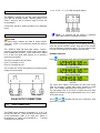
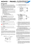
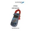
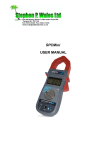
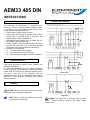
AEM33 485 DIN
INSTRUCTIONS
1
SAFETY
This instrument is manufactured in compliance with
EN61010-1 Cat III for nominal operating voltages of 400V
L-L and 230V L-N, to ensure safe operation the user must
comply with the following instructions:
• Ensure that the supply voltage is correct.
• The auxiliary mains supply is internally fused at 250V,
100mA Type 2. External fusing is required if the
auxiliary supply voltage exceeds 250V.
• Maintenance and/or repairs must be carried out only
by qualified, authorised personnel.
• If there is ever the suspicion that safe use is no longer
possible, the instrument must be disconnected and
precautions must be taken against accidental use.
• Operation is no longer safe:
1)
If there is clearly visible damage
2)
If the instrument no longer functions
3)
After prolonged storage in unsuitable conditions.
1.1
3
CONNECTION DIAGRAMS
(OPT)
OPERATOR SAFETY
Read these instructions carefully before installing and
utilising the instrument.
The instrument described in this user manual is intended
for use by properly trained staff only. Maintenance and/or
repairs must be carried out by authorised personnel only.
For proper, safe use of the instrument and for
maintenance and/or repair, it is essential that the persons
instructed to carry out these procedures follow normal
safety precautions.
2
SYMBOLS
CAUTION: Failure to follow the instructions may result
in personal injury or damage to equipment.
NOTE: Failure to follow the instructions may result
in an instrument malfunction.
CAUTION: The instrument is internally fused at 250V
100mA. External fusing is required if the supply voltage
exceeds 250V.
3.1
CONNECTION OF THE CURRENT INPUT
15 = A 16 = B 17 = 0 V ( A&B are signal cables.)
The AEM33 is suitable for use with current transformers
(CTs) with 5A secondary output. Metering quality CTs of
Class 1 accuracy with a minimum rating of 2.5VA are
recommended.
Connections should be made according to the diagrams
above.
3.2
NOTE: It is essential that the polarity is respected
when other units are connected to the bus.
PULSE OUTPUT CONNECTIONS
CAUTION:
The pulse output contacts are rated at 100mA AC/DC,
100V max. Under no circumstances should this rating be
exceeded.
The AEM33 is fitted with dual pulse outputs. Output 1
provides a pulse proportional to kWh, output 2 provides a
pulse proportional to kVArh. Each output has a telltale
l.e.d. on the front panel which flashes ‘on’ to indicate a
pulse being generated.
4
INSTRUMENT OPERATION & SET-UP
When the instrument is powered up, the display will initially
show the internal software version, then after a few seconds
will start displaying measured values. The four buttons allow
the user to scroll through the available measurements.
ENERGY DISPLAYS
Press
to select kWh, kVArh and Hours Run display pages.
The pulse connections are as follows:
Pulse 1: Terminals 31 & 32
Pulse 2: Terminals 29 & 30
The contacts are volt free and therefore an external power
supply must be provided.
The Hours Run register accumulates the total time during
which the average 3 phase load current exceeds a preset
level. This is always displayed with a resolution 0.1 hour.
The percentage level of (l1+l2+l3) at which the Hours Run
register accumulates is user programmable from 1% to 100%
of full scale current.
and
together and hold for 2 seconds to reset
Press
the hours run register.
3.3
RS485 CONNECTIONS
The RS485 output consists of 3 terminals (15, 16 & 17) at
the top left of the unit. These should be connected via the
correct specification cable to the data bus. (Refer to
Elcomponent for cable recommendations.)
Terminal
connections are as follows:
5, 10, 15, 20, 30, 40, 50, 60, 80, 100, 150, 200, 250, 300, 400,
500, 600, 800, 1000, 1200, 1250, 1500, 1600, 2000, 2400,
3000, 2500, 4000, 4500, 5000, 5500, 6000, 6500, 7000, 7500,
8000, 8500, 9000, 9500, 10000, 10500, 11000, 11500, 12000,
12500, 13000, 13500, 14000, 14500, 15000, 15500, 16000,
16500, 17000, 17500, 18000, 18500, 19000, 19500, 2000,
205000, 21000, 21500, 22500, 23000, 23500, 24000, 24500,
25000
VOLTAGE DISPLAYS
Press
to select from the following displays:
Press the S or T key until the desired current is displayed. If
the desired CT value is not present in the above list, the ratio
may be ‘fine adjusted’ as follows: Press and hold the W and S
buttons simultaneously for 2 seconds to enter ‘Fine Adjust
Mode’. This is indicated by a decimal point displayed
immediately to the right of the defined parameter viz: “Ct.” this
enables the CT primary value to be changed in 10A steps until
the desired ratio is displayed. Press the W key to store the
value and advance the page.
CURRENT DISPLAYS
Press
to select the following display
:
POWER DISPLAYS
Press
VT SET-UP
The default voltage setting is 400V and this value should not
be altered.
to select from the following displays:
PULSE SET-UP
The pulse rate value (PLr) may be set between 0.1 and 100
pulses per unit. Press the S or T key until the desired pulse
is displayed. Note that the unit of energy (Wh/kWh/MWh) will
automatically change to reflect the primary values of CT & VT
previously set. The pulse value is set for both outputs during
the process. Press the W key to store the value and advance
the page.
The pulse duration value (PLt) may be set in increments
between 100mS & 20 seconds as required.
NOTE: The values for phase power factor may be
used to verify correct CT position & orientation.
INSTRUMENT SET-UP
The display shows the CT set-up screen. The instrument
settings are entered from this point, starting with the CT
values.
CT SET-UP
To enter programming mode press
and
simultaneously for 5 seconds. The CT primary value may
then be set from the following nominal values (secondary
value must be 5A):
The Pulse Output Test (Pto) allows the meter pulse output and
connected data collection hardware to be tested, regardless of
whether an actual load is present. Press the S button to start
the test. The display will show “Ptr” and both outputs will pulse
simultaneously. This is verified by the front panel l.e.d.s.
Press the S and T together to stop the test and reset the test
counter.
HOURS RUN SET-UP
The hours run preset level may be set between 1% and 100%
of the full scale current. Press the S or T key until the
desired value is displayed. Press the W key to store the value
and advance the page.
RS485 SET-UP
This allows the baud rate and MODBUS address to be set.
Use the S and T buttons to set the desired baud rate.
Press the W key to store the value and advance the page.
Use the S and T buttons to set the unit address. Press
the W key to store the value and save and exit from the
set-up menu. The display will show ‘storing’ to confirm this
action.
5
TECHNICAL CHARACTERISTICS
Connection:
3 Phase 3 or 4 wire Unbalanced, 3 Phase
Balanced, Single Phase Load.
Inputs:
Voltage: 400/230V 3 Phase 3/4 wire
Current: 5A – External CTs.
Fully
isolated.
Burden:
<0.1VA per phase Current/Voltage
Pulse Output: Opto isolated volt free contact
Rating: 100mA ac/dc, 100V ac/dc max
Value: 1 pulse per kWh
1 pulse per 10 kWh
1 pulse per 100 kWh
1 pulse per 1000 kWh
Duration: 100ms
Isolation: 2.5kV for 1 minute
Power Supply: 230V 50/60Hz +/- 15%
Overload:
Voltage x 4 for 1 hour
Current x 40 for 0.5 seconds max
Consumption: 2VA
Weight:
325g
IP Rating:
Instrument = IP20 Front panel = IP40
Temp Range: -10o - +65o
Dims:
106w x 58d x 90h mm (6 DIN)
NOTE: Do not expose the instrument display to
direct sunlight.
Unit 5 Southmill Trading Centre, Southmill Road, Bishop’s
Stortford, Herts. CM23 3DY.
01279 503173 [email protected]
www.elcomponent.co.uk
29.06.09 – Issue 3