1
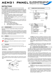
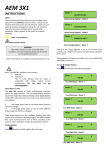
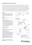
AEM31-E
SUPPLEMENT
AR
Y
SUPPLEMENTAR
ARY
INSTRUCTIONS
The AEM31-E is an ethernet enabled kWh meter based on the AEM31 DIN.
Please refer to the AEM31-DIN instruction sheet for information. The following
additional items should also be noted:
CONNECTIONS
All power supply, voltage connections and current (CT) input connections
are identical to the AEM31 DIN. There is no pulse output fitted to the AEM31E
INSTRUMENT PROGRAMMING
The instrument requires a standard RJ45 Cat 5 or equivalent cable
connection to an ethernet system. See the relevant documentation for
MeterRing 2000 sub-metering software for further information. The
ACT and LINK leds on the right hand side of the front panel follow
standard ethernet conventions. LINK is illuminated when the unit is
correctly connected to an ethernet hub, ACT is illuminated to indicate
communication is taking place.
INSTRUMENT PROGRAMMING
The CT ratio set up is also identical to the AEM31 DIN. However additional
setting up of the network and IP address is also required. This is carried
out via the ethernet connection after installation is complete.
Unit 5 Southmill Trading Centre, Southmill Road,
Bishop’s Stortford, Herts. CM23 3DY
Tel: 01279 503173 Fax: 01279 654441
[email protected]
10/01
AEM31DIN
INSTRUCTIONS
1
SAFETY
This instrument was manufactured and tested in compliance with class 2
IEC 1010 and VDE 411 standards, in accordance with group B VDE 0110
standards for operating voltages up to 250 VACrms phase to neutral. It is
suitable for use on 3 phase 4 wire (star) systems and single phase supplies.
To maintain this condition and to ensure safe operation, the user must
comply with the following instructions:
•
Ensure that the operating voltage is correct for the supply.
•
The power supply does not require an earth connection.
•
A 50 mA T Type fuse should be installed in the power supply circuit
to the instrument i.e. phase 1.
•
Maintenance and/or repairs must be carried out only by qualified,
authorised personnel.
•
If there is ever the suspicion that safe use is no longer possible, the
instrument must be disconnected and precautions must be taken
against accidental use;
•
Operation is no longer safe when;
1)
there is clearly visible damage
2)
the instrument no longer functions
3)
after prolonged storage in unsuitable conditions;
1.1
OPERATOR SAFETY
Read these instructions carefully before installing and utilising the
instrument.
The instrument described in this user manual is intended for use by properly
trained staff only. Maintenance and/or repairs must be carried out by
authorised personnel only. For proper, safe use of the instrument and for
maintenance and/or repair, it is essential that the persons instructed to carry
out these procedures follow normal safety precautions.
1.2
SINGLE PHASE
2.2
3 PHASE STAR
CONNECTION OF THE CURRENT (CT) INPUT
The AEM31D is suitable for use with current transformers (CTs) with 5A
secondary output. Metering quality CTs of Class 1 accuracy with a minimum
rating of 2.5VA are recommended. See over for the table of CT ratios
which can be utilised with this instrument.
Connection should be made according to the following diagrams. For 3
phase supplies one side of the CT secondaries (S1) should be connected
to the relevant input terminal (Red phase to L1, Yellow to L2 and Blue to
L3). The remaining CT Terminals (S2) are commoned to the COM terminal
which should also be earthed as shown.
Single phase connection is to L1 and COM only.
SYMBOLS
This symbol means “Read the Instructions”
2
POWER SUPPLY
The instrument must have power supply with voltage ranging from 200240VAC 50/60 Hz using max. cable gauge 2.5 mm2 and attached to the
power supply terminals (see Fig below). The instrument power supply
does not need an earth connection. The instrument requires the installation
of an external 50mA T type fuse in the power supply circuit.
2.1
CONNECTION OF THE VOLTAGE INPUT
Cables should be of 2.5mm2 max diameter, connected as shown in the following
diagrams.
NB: The AEM31D is an advanced design which automatically
compensates for reversed CTs and incorrect phase rotation. However
the relationship between current and voltage inputs must be respected
(ie if red phase volts is connected to L1, the red phase CT must be
connected to L1 etc).
2.3
5
CONNECTION OF THE PULSE OUTPUT
WIRING DIAGRAM
CAUTION: The pulse output contacts are rated at 27VAC 20mA/
27VDC 20 mA. Under no circumstances should this rating be
exceeded.
The pulse output connection is made via the two terminals marked
‘pulse’ (see wiring diagram). The contacts are volt-free and
therefore an external power source must be provided. Contacts
are normally open, and provide an output of 1 pulse per kWh. Pulse
duration (contacts closed) is 400/500 msec.
Pulse Ouput
3
INSTRUMENT PROGRAMMING
“WAIT” appears when the instrument is first powered up. After a few
seconds the power measurement will be displayed (the LED on the w key
is lit).
The programming key “ “ is located at the bottom left corner of the front
panel.
To enter into programming mode, simultaneously press the
w key
key and the
On the display the CT selection will appear.
A
5/5
Pressing the w key will scroll through the available CT ratios.
(See table.) When the desired selection is displayed, press the
programming key
to confirm, and exit setup mode.
S E LE C TAB LE C T
R ATIOS
NOTE: Unless the CT ratio is programmed the default value will be 5/5 (no
multiplier).
To reset the kWh value to zero press the
simultaneously
key and the
kWh
key
Once programmed, the setup and reset capability can be disabled by cutting
the jumper wire located under the CT input terminal cover. The cover may
be levered off with a small screwdriver to reveal the jumper to the right of
the CT input terminals. Once the jumper is cut, the reset and setup is
permanently disabled unless the jumper connection is remade.
4
TECHNICAL CHARACTERISTICS
Connection:
Inputs:
Input Overload:
Pulse Output:
Number of Scales:
Weight:
IP rating:
Temp Range:
Relative Humidity:
Condensation:
Isolation
Dims:
3 phase star or single phase
Voltage: 250V from 20 to 800 Hz
Current: 5A from 20 to 800 Hz
Voltage: Max 264 Vrms phase to neutral
Current; Max 20 Arms
Opto isolated volt free contact
Rating - 100mA 250 VAC
Value - 1 pulse per kWh
Duration - 400-500 msec
2 current scales
1 current voltage
270g.
Instrument = IP20 Front Panel = IP40
From -10oC to +40oC
RH Max 90%
Not permitted.
In accordance with group B VDE 0110
standards for 250 VACrms operating voltages.
70w x 57.5d x 90h (mm)
N.B: Do not expose the instrument display to direct sunlight.
5/5
500/5
25/5
600/5
40/5
750/5
50/5
800/5
60/5
1000/5
75/5
1200/5
80/5
1250/5
100/5
1500/5
120/5
1600/5
150/5
1800/5
200/5
2000/5
250/5
2500/5
300/5
3200/5
320/5
4000/5
400/5
Unit 5 Southmill Trading Centre, Southmill Road,
Bishop’s Stortford, Herts. CM23 3DY
Tel: 01279 503173 Fax: 01279 654441
[email protected]
10/03