1
SL1100
Networking Manual
NDA-31190
Issue 4.0
NEC Corporation reserves the right to change the specifications, functions, or features at any time
without notice.
NEC Corporation has prepared this document for use by its employees and customers. The
information contained herein is the property of NEC Corporation and shall not be reproduced without
prior written approval of NEC Corporation.
All other brand names and product names referenced in this document are trademarks or registered
trademarks of their respective companies.
Copyright 2014
NEC Corporation of America
6535 N. State Highway 161
Irving, TX 75039-2402
Communications Technology Group
Table of Contents
___________________________________________________________________________________
SL1100
Chapter 1 Introduction
Section 1
General Overview................................................................... 1-1
Section 2
Common Terms...................................................................... 1-1
Chapter 2 General Information
Section 1
Voice Over IP ......................................................................... 2-1
Chapter 3 IP Networking
Section 1
Introduction ............................................................................ 3-1
Section 2
IP Trunks................................................................................. 3-1
2.1
Configure IP Trunks ............................................................................ 3-2
Chapter 4 General IP Configuration
Section 1
Introduction ............................................................................ 4-1
Section 2
Network Addressing Overview ............................................. 4-2
2.1
IP Address ........................................................................................... 4-2
2.2
Subnet Mask ........................................................................................ 4-2
2.3
DHCP ................................................................................................... 4-3
Section 3
Configuration Examples........................................................ 4-3
3.1
Example Configuration 1 - Existing Network with Static Addressing ... 4-3
___________________________________________________________________________________
Networking Manual
i
Issue 4.0
NEC SL1100
___________________________________________________________________________________
Section 4
Testing the NEC SL1100 Network Connection ................... 4-6
Chapter 5 Programming
Section 1
Before You Start Programming ........................................... 5-1
Section 2
How to Enter Programming Mode........................................ 5-2
Section 3
How to Exit Programming Mode .......................................... 5-3
Section 4
Using Keys to Move Around in the Programs .................... 5-4
Section 5
Programming Names and Text Messages........................... 5-5
Section 6
Using Softkeys For Programming........................................ 5-6
Section 7
What the Softkey Display Prompts Mean ............................ 5-7
Section 8
Programs ................................................................................ 5-7
10-12 : CPU Network Setup ..................................................................... 5-8
10-13 : In-DHCP Server Setup ............................................................... 5-11
10-14 : Managed Network Setup ............................................................ 5-12
10-15 : Client Information Setup ............................................................. 5-13
10-16 : Option Information Setup ........................................................... 5-14
10-19 : VoIP DSP Resource Selection ................................................... 5-18
10-62 : NetBIOS Setting ......................................................................... 5-19
10-63 : DHCP Client Setting ................................................................... 5-20
Program 20 : System Option Setup .......................................................... 5-21
15-05 : IP Telephone Terminal Basic Data Setup .................................. 5-21
84-09 : VLAN Setup ................................................................................ 5-25
84-10 : ToS Setup .................................................................................. 5-26
Program 90 : Maintenance Program ......................................................... 5-28
90-23 : Deleting Registration of IP Telephones ...................................... 5-28
90-34 : Firmware Information ................................................................. 5-29
___________________________________________________________________________________
ii
Table of Contents
NEC
SL1100
Issue 4.0
__________________________________________________________________________________
Chapter 6 Network Design Considerations
Section 1
Introduction ........................................................................... 6-1
Section 2
QoS.......................................................................................... 6-1
2.1
QoS Definitions .................................................................................... 6-1
2.2
Voice Quality Improvements ................................................................ 6-3
2.3
Types of Classifications for Traffic for QoS ......................................... 6-4
Section 3
Internet Based Connections (xDSL, Cable, etc.) ................ 6-6
Section 4
Firewalls and NAT ................................................................. 6-7
4.1
Understanding the Infrastructure ......................................................... 6-7
4.2
Firewall Integration .............................................................................. 6-8
4.3
Virtual Private Network (VPN) Tunnelling ............................................ 6-9
Section 5
CODEC and Bandwidth ...................................................... 6-11
5.1
CODECs ............................................................................................ 6-11
5.2
Bandwidth .......................................................................................... 6-13
Section 6
Quality of Service (QoS) Implementation .......................... 6-13
6.1
Prioritization ....................................................................................... 6-14
6.2
Layer 2 QoS (802.1pq) ...................................................................... 6-16
6.3
Layer 3 QoS ....................................................................................... 6-20
6.4
IP Precedence ................................................................................... 6-22
6.5
Diffserv (Differentiated Service) ......................................................... 6-23
6.6
Comparison of IP Precedence and Diffserv Values ........................... 6-24
6.7
Programming QoS in the NEC SL1100 System ................................ 6-27
6.7.1
Marking Voice Traffic - Program 84-10-XX .................................... 6-27
6.7.2
NEC SL1100 Voice Protocols ........................................................ 6-27
___________________________________________________________________________________
Networking Manual
iii
Issue 4.0
NEC SL1100
___________________________________________________________________________________
Section 7
6.7.3
Configuring Diffserv ....................................................................... 6-27
6.7.4
Configuration Examples for Classification and Queuing ................ 6-29
Port Designations .............................................................. 6-31
Chapter 7 SIP Trunking
Section 1
VoIP......................................................................................... 7-1
Section 2
IP Networking......................................................................... 7-1
Section 3
SIP Trunking........................................................................... 7-2
3.1
Introduction .......................................................................................... 7-2
3.1.1
SIP Trunking Requirements ............................................................ 7-3
3.1.2
SIP Trunking Setup ......................................................................... 7-4
Section 4
SIP Trunk Overview ............................................................... 7-5
4.1
General Information ............................................................................. 7-5
4.2
Supported Protocols ............................................................................ 7-5
4.3
Supported SIP Methods ...................................................................... 7-6
4.4
Supported SIP Trunking Options ......................................................... 7-6
4.5
Supported CODEC .............................................................................. 7-7
Section 5
Supported SIP Trunking Functions ..................................... 7-7
5.1
Address Resolution ............................................................................. 7-7
5.2
Authentication Process ........................................................................ 7-7
5.3
Caller ID ............................................................................................... 7-8
5.4
Carrier Support .................................................................................... 7-8
5.5
Early Media .......................................................................................... 7-8
5.6
Fault Tolerance .................................................................................... 7-8
5.7
Network Address Port Translation (NAPT) .......................................... 7-9
___________________________________________________________________________________
iv
Table of Contents
NEC
SL1100
Issue 4.0
__________________________________________________________________________________
5.8
Quality of Service (QoS) ...................................................................... 7-9
5.9
Registration .......................................................................................... 7-9
Section 6
5.9.1
Registration Process ........................................................................ 7-9
5.9.2
Registration Recover Process ......................................................... 7-9
SIP Trunk Programming ...................................................... 7-10
6.1
SIP Trunk Basic Setup
................................................................... 7-10
6.2
IP DSP Resource ............................................................................... 7-13
6.3
SIP Authentication Information .......................................................... 7-14
6.4
SIP Caller ID ...................................................................................... 7-16
6.5
SIP CODEC Trunk ............................................................................. 7-17
6.6
SIP DNS Setup .................................................................................. 7-23
6.7
SIP NAPT Router Setup .................................................................... 7-23
6.8
SIP System Interconnection Setup .................................................... 7-24
6.9
SIP Protocol ....................................................................................... 7-24
6.10
SIP Server Information Setup ............................................................ 7-25
6.11
SIP Registrar Setup ........................................................................... 7-26
6.12
SIP Server Status .............................................................................. 7-27
6.13
SIP Trunk Registration Information Setup ......................................... 7-28
6.14
SIP UPnP ........................................................................................... 7-28
Chapter 8 DHCP Client
Section 1
DHCP Client ............................................................................ 8-1
Section 2
DHCP Server Configuration Example .................................. 8-5
Chapter 9 IP Multiline Station (SIP)
Section 1
Introduction ............................................................................ 9-1
___________________________________________________________________________________
Networking Manual
v
Issue 4.0
NEC SL1100
___________________________________________________________________________________
Section 2
IP to TDM Conversion ........................................................... 9-1
2.1
DR700 IP Multiline Telephones ........................................................... 9-2
2.2
Conditions ............................................................................................ 9-3
2.3
LAN Connection .................................................................................. 9-4
Section 3
Providing Power ................................................................... 9-5
3.1
Local Power ........................................................................................ 9-5
3.2
Power Over Ethernet (PoE) ................................................................ 9-5
Section 4
Peer-to-Peer ........................................................................... 9-6
Section 5
Programming ......................................................................... 9-6
5.1
Section 6
Music on Hold ..................................................................................... 9-7
Configuration Examples ...................................................... 9-7
6.1
Example Configuration 1 - Static IP Addressing, One LAN ................. 9-8
6.2
Example Configuration 2 - Dynamic IP Addressing, One LAN ............ 9-9
6.3
Example Configuration 3 - Static IP Addressing, Routed WAN ......... 9-11
Section 7
IP Phone Programming Interface ...................................... 9-12
Section 8
DHCP Server Configuration ............................................... 9-12
Section 9
Configuring Quality of Service .......................................... 9-13
9.1
Layer 2 Priority Control ...................................................................... 9-14
9.1.1
9.2
Programming Layer 2 Priority Control ........................................... 9-14
Layer 3 (ToS) Priority Control ........................................................... 9-15
9.2.1
Programming Layer 3 Priority Control ........................................... 9-15
Section 10
IP Telephone Registration and Deletion ........................... 9-15
Section 11
System IP Phones and Analog Trunks ............................. 9-16
___________________________________________________________________________________
vi
Table of Contents
NEC
SL1100
Issue 4.0
__________________________________________________________________________________
Section 12
Firmware Upgrade Procedure............................................. 9-16
12.1
Manually Upgrading Firmware ........................................................... 9-16
12.2
Checking the Firmware Version ......................................................... 9-17
12.3
Upgrading Automatically .................................................................... 9-17
Section 13
IP Station (SIP Multiline Telephone)................................... 9-18
13.1
Description ......................................................................................... 9-18
13.2
IP Addressing .................................................................................... 9-20
13.3
IP Phone Registration Modes ............................................................ 9-20
13.4
General IP Configuration ................................................................... 9-23
13.5
VLANs ................................................................................................ 9-23
13.5.1
Logging In on the PC ..................................................................... 9-24
13.5.2
Tagging Voice Packets Using IP Phone ........................................ 9-26
13.5.3
Tagging Data Packets Using IP Phone .......................................... 9-28
13.5.4
Entering VLAN Settings by Phone (Voice Packets Only) .............. 9-31
13.5.5
Entering VLAN Settings for PC Port by Phone
(Data Packets Only) ....................................................................... 9-31
13.6
ToS Settings (Layer 3 QoS) ............................................................... 9-32
13.7
Bandwidth .......................................................................................... 9-40
13.8
Some Network Considerations .......................................................... 9-43
13.9
Guide to Feature Programming ......................................................... 9-48
13.10 SIP MLT Quick Startup Guide ........................................................... 9-59
13.10.1 Plug and Play ................................................................................. 9-59
13.10.2 Automatic Registration ................................................................... 9-63
13.10.3 Manual Registration ....................................................................... 9-67
13.11 IP Phone Relocation .......................................................................... 9-69
Section 14
NAPT ..................................................................................... 9-71
___________________________________________________________________________________
Networking Manual
vii
Issue 4.0
NEC SL1100
___________________________________________________________________________________
14.1
Introduction ........................................................................................ 9-71
14.2
SL1100 Requirements ....................................................................... 9-73
14.3
14.2.1
Main Software ................................................................................ 9-73
14.2.2
Hardware ....................................................................................... 9-73
14.2.3
Capacity ......................................................................................... 9-73
Installation ......................................................................................... 9-73
14.3.1
Settings for terminals ..................................................................... 9-73
Section 15
Conditions ............................................................................ 9-75
Section 16
Restrictions – Static NAT.................................................... 9-75
Section 17
Minimum Required Programming ...................................... 9-76
Chapter 10 IP Single Line Telephone
Section 1
Introduction.......................................................................... 10-1
Section 2
Programming ....................................................................... 10-3
2.1
Card Setup ........................................................................................ 10-3
2.2
Configure VoIPDB Networking Information ....................................... 10-4
2.3
2.2.1
VoIPDB (DSP) Basic Setup ........................................................... 10-4
2.2.2
VoIP ToS Setup ............................................................................. 10-5
2.2.3
SIP Peer to Peer ............................................................................ 10-5
2.2.4
IP Extension Numbering ................................................................ 10-6
2.2.5
SIP Extension CODEC Information ............................................... 10-6
2.2.6
SIP Extension Basic Information Setup ....................................... 10-10
2.2.7
IP Phone Configuration ............................................................... 10-11
2.2.8
NAT Mode for Standard SIP terminal (Version 4.0 or higher)
2.2.9
NTP Time Server ....................................................................... 10-16
... 10-12
SIP Phone Example ....................................................................... 10-17
___________________________________________________________________________________
viii
Table of Contents
NEC
SL1100
Issue 4.0
__________________________________________________________________________________
Chapter 11 NAPT
Section 1
NAPT ..................................................................................... 11-1
1.1
Introduction ........................................................................................ 11-1
1.2
SL1100 Requirements ....................................................................... 11-3
1.3
1.2.1
Main Software ................................................................................ 11-3
1.2.2
Hardware ....................................................................................... 11-3
1.2.3
Capacity ......................................................................................... 11-3
1.2.4
License .......................................................................................... 11-3
Installation .......................................................................................... 11-3
1.3.1
Settings for terminals ..................................................................... 11-3
Section 2
Conditions ............................................................................ 11-5
Section 3
Restrictions – Static NAT .................................................... 11-5
Section 4
Minimum Required Programming ...................................... 11-6
Chapter 12 All DSP Busy Indication
Section 1
Introduction .......................................................................... 12-1
Section 2
Service Conditions............................................................... 12-2
Section 3
Related Features .................................................................. 12-3
Section 4
Guide to Feature Programming .......................................... 12-3
Chapter 13 SL Net
Section 1
Introduction .......................................................................... 13-1
Section 2
System Capacity .................................................................. 13-3
___________________________________________________________________________________
Networking Manual
ix
Issue 4.0
NEC SL1100
___________________________________________________________________________________
Section 3
Network Requirements........................................................ 13-4
Section 4
Quality of Service Settings (QOS)...................................... 13-5
Section 5
IP Precedence ...................................................................... 13-5
Section 6
Diffserv ................................................................................. 13-7
6.1
Conditions .......................................................................................... 13-8
Section 7
Guide to Feature Programming........................................ 13-12
Section 8
Programming Examples.................................................... 13-36
8.1
Section 9
Basic SL Net Setup
....................................................................... 13-36
List of Supported Features in a Networked System....... 13-42
___________________________________________________________________________________
x
Table of Contents
List of Figures
___________________________________________________________________________________
SL1100
Figure 3-1
Example of SL1100 IP Network Configuration ........................................................... 3-2
Figure 4-1
Example Configuration 1 - Existing Network with Static IP Address .......................... 4-4
Figure 4-2
Example Configuration 1 - Adding the NEC SL1100 KSU to the Network ................. 4-5
Figure 4-3
Testing the Network Connection ................................................................................ 4-6
Figure 6-1
Layer 2 Diagram (802.1Q) .......................................................................................... 6-5
Figure 6-2
Virtual Private Network (VPN) Example ................................................................... 6-10
Figure 6-3
Network Bottleneck Example ................................................................................... 6-14
Figure 6-4
Voice and Data Network Implementation ................................................................. 6-15
Figure 6-5
Priority Queuing on Voice and Data Networks ......................................................... 6-16
Figure 6-6
Protocol Structure for Layer 2 QoS .......................................................................... 6-17
Figure 6-7
Layer 3 QoS Example .............................................................................................. 6-20
Figure 6-8
Common Network with Cisco Router ....................................................................... 6-29
Figure 7-1
Common IP Network using NEC SL1100 SIP Trunk .................................................. 7-3
Figure 8-1
DHCP - Set Predefined Options ................................................................................. 8-5
Figure 8-2
DHCP - Predefined Options and Values .................................................................... 8-6
Figure 8-3
DHCP - Scope Options .............................................................................................. 8-7
Figure 8-4
DHCP - Data Entry for 1st DHCP Server .................................................................. 8-8
Figure 9-1
DR700 IP Telephone (ITL) ......................................................................................... 9-2
Figure 9-2
Typical Network IP Connection .................................................................................. 9-4
Figure 9-3
Example Configuration 1 - Static IP Addressing, One LAN ....................................... 9-8
Figure 9-4
Example Configuration 2 - Dynamic IP Addressing, One LAN ................................. 9-10
Figure 9-5
Example Configuration 3 - Static IP Addressing, Routed WAN ............................... 9-11
Figure 9-6
DR700 Encryption .................................................................................................... 9-22
Figure 9-7
Log In to IP Phone .................................................................................................... 9-25
Figure 9-8
LAN Port Settings Window ....................................................................................... 9-26
___________________________________________________________________________________
Networking Manual
xi
Issue 4.0
NEC SL1100
___________________________________________________________________________________
Figure 9-9
VLAN Mode .............................................................................................................. 9-27
Figure 9-10
VLAN ID ................................................................................................................... 9-27
Figure 9-11
VLAN Priority ............................................................................................................ 9-27
Figure 9-12
PC Port Settings Window ......................................................................................... 9-28
Figure 9-13
Port VLAN Mode ...................................................................................................... 9-29
Figure 9-14
Port VLAN ID ............................................................................................................ 9-29
Figure 9-15
Port VLAN Priority .................................................................................................... 9-29
Figure 9-16
Save Network Settings ............................................................................................. 9-30
Figure 9-17
Save Confirmation Window ...................................................................................... 9-30
Figure 9-18
84-10: ToS Setup ..................................................................................................... 9-34
Figure 9-19
SIP MLT Basic Setup ............................................................................................... 9-36
Figure 9-20
Type of Service Window .......................................................................................... 9-38
Figure 9-21
RTP - Voice Packets ................................................................................................ 9-39
Figure 9-22
SIP - Signalling Packets ........................................................................................... 9-39
Figure 9-23
NEC SL1100 Network Example No. 1 ..................................................................... 9-44
Figure 9-24
NEC SL1100 Network Example No. 2 ..................................................................... 9-45
Figure 9-25
IP System Operation Setup ...................................................................................... 9-47
Figure 9-26
System Data 10-12: CD CP00 Network Setup ......................................................... 9-59
Figure 9-27
System Data 84-26: VoIPDB Basic Setup (DSP) ..................................................... 9-60
Figure 9-28
System Data 11-02: Extension Numbering .............................................................. 9-61
Figure 9-29
IP Phone List ............................................................................................................ 9-61
Figure 9-30
IP Phone List ............................................................................................................ 9-63
Figure 9-31
DR700 Server Information Setup ............................................................................. 9-64
Figure 9-32
Automatic Registration Basic Setup ......................................................................... 9-64
Figure 9-33
Automatic Registration Personal ID Index ............................................................... 9-64
Figure 9-34
Automatic Registration User Name and Password Assignment .............................. 9-65
Figure 9-35
DR700 Server Information Setup ............................................................................. 9-67
Figure 9-36
NAPT Configuration Example .................................................................................. 9-72
Figure 11-1
NAPT Configuration Example .................................................................................. 11-2
Figure 13-1
System Capacity Diagram ........................................................................................ 13-3
____________________________________________________________________________________
xii
List of Figures
NEC SL1100
Issue 4.0
___________________________________________________________________________________
Figure 13-2
IP Precedence .......................................................................................................... 13-6
Figure 13-3
Setup Example ......................................................................................................... 13-8
Figure 13-4
Programming Example ........................................................................................... 13-36
___________________________________________________________________________________
Networking Manual
xiii
Issue 4.0
NEC SL1100
___________________________________________________________________________________
THIS PAGE INTENTIONALLY LEFT BLANK
____________________________________________________________________________________
xiv
List of Figures
List of Tables
___________________________________________________________________________________
SL1100
Table 1-1
Common Terms and Associated Abbreviations .............................................................. 1-1
Table 2-1
VoIP Specifications ......................................................................................................... 2-1
Table 5-1
Keys for Entering Data .................................................................................................... 5-4
Table 5-2
Keys for Entering Names ................................................................................................. 5-5
Table 5-3
Softkey Display Prompts .................................................................................................. 5-7
Table 6-4
Type of Service Field (IP Precedence - i Ref. REC 1349) ............................................. 6-22
Table 6-5
Diffserv Parameters ........................................................................................................ 6-23
Table 6-6
IP Precedence and Diffserv Values Comparison ........................................................... 6-25
Table 6-7
Cisco Router Configuration Example ............................................................................. 6-30
Table 9-1
IP Phone Programming Options User Menu ................................................................. 9-12
Table 9-2
DR700 Supported Encryption ......................................................................................... 9-22
Table 9-3
Common IP Precedence/Diffserv Values and Hexadecimal Equivalent ........................ 9-37
Table 9-4
IP Phone Relocation ....................................................................................................... 9-70
Table 12-1 Alarm Types .................................................................................................................. 12-1
Table 13-1 Bandwidth per VoIP Call ............................................................................................... 13-5
Table 13-2 Diffserv Parameters ........................................................................................................ 13-7
___________________________________________________________________________________
Networking Manual
xiii
Issue 4.0
NEC SL1100
___________________________________________________________________________________
THIS PAGE INTENTIONALLY LEFT BLANK
___________________________________________________________________________________
xiv
List of Tables
1
Introduction
SECTION 1
GENERAL OVERVIEW
SECTION 2
COMMON TERMS
The following terms and the associated abbreviations or alternate
nomenclature may be found throughout this document.
Table 1-1 Common Terms and Associated Abbreviations
Term
Abbreviation
Description
CD-CP00-US
CPU-B1
SL1100 CPU
CPU
CPU-B1 with main software (CPU is shipped with KSU)
IP4WW-VOIPDB-C1
VOIPDB
VOIP Daughter Board
Mount this card onto the CPU card (VoIPDB slot) at
Main KSU. Max. 32 channels by license control.
IP4WW-4COIDB-B1
4COIDB
The 4COIDB provides four analog trunks and is
mounted on the 084M, 080E or 008E card.
IP4WW-080E-B1
080E card
8-digital station interface card
IP4WW-12TXH-B TEL 2-wire Digital Multiline
IP4WW-24TXH-B TEL Telephone
12TXH-B TEL 12-button digital telephone
24TXH-B TEL 24-button digital telephone
IP4[ ]-24TIXH-C TEL
24TIXH-C TEL 24-button IP telephone
Networking Manual
IP Multiline Telephone
Introduction
This manual provides information for networking for the NEC SL1100
system.
1-1
Issue 4.0
NEC SL1100
THIS PAGE INTENTIONALLY LEFT BLANK
1-2
Introduction
2
General Information
SECTION 1
VOICE OVER IP
As most organizations already have existing data networks in place,
considerable cost savings can be achieved by utilizing spare bandwidth on
these networks for voice traffic.
NEC SL1100 supports the use of IP Phones. These telephones provide
the same functionality as a multiline telephone but use the data network
rather then the traditional telecoms infrastructure. This can reduce costs
and allow the use of NEC SL1100 telephones in locations that would not
normally be supported by multiline telephones.
General Information
Voice over IP (VoIP) is a technology that converts speech into data
packets and transmits these packets over TCP/IP networks. The
technology also facilitates compression and silence suppression to reduce
network bandwidth demands.
Table 2-1 VoIP Specifications lists the specifications for various aspects of
NEC SL1100 VoIP system.
Table 2-1 VoIP Specifications
Category
Notes
DHCP Server
CPU-B1/VoIPDB
DHCP Client
VoIPDB/IP Phone
802.1p/1q
CPU-B1
L3 QoS (ToS)
Diffserv/IP Precedence
Maintenance
HTTP Server
CPU-B1/VoIPDB
VLAN
Tag and port-based VLAN
IP Address
QoS
Networking Manual
Feature
2-1
Issue 4.0
NEC SL1100
Table 2-1 VoIP Specifications (Continued)
Category
Feature
Notes
G.711 µ-law/A-law
G.729a
VoCoder
G.722
G.723
G.726
iLBC
2-2
Jitter Buffer Size
Set by system programming
RTP Length
Set by system programming
Echo Canceller Tail
Size
Set by system programming
Level Adjustment
Set by system programming
IP Phone
SIP Phone
SIP Phone
SIP Trunk
SIP Trunk
Maximum 32 Trunks
DHCP Server and DHCP Client cannot be used at the same time. When the
DHCP Server is enabled the DHCP Client function cannot be activated.
When the VoIPDB is installed, the CPU-B1 is no longer active, all IP connections
go through the VoIPDB.
General Information
IP Networking
SECTION 1
INTRODUCTION1
IP TRUNKS
The SIP Trunks method of networking allows connection to SIP devices.
This could be a PBX system or a third-party product. When using SIP, the
feature set is limited and the advanced networking features cannot be
used.
IP Networking
IP Networking uses VoIP technology to connect two or more telephone
systems together. This allows calls to be made between sites without
using the public telephone network. This saves considerable money, and
makes communication between sites much easier.
SECTION 2
3
Refer to SIP Trunking for a a detailed description of SIP trunking and for
set up instructions.
To set up IP trunks:
1.
1.
Connect the system to the Data Network. (Refer to General IP
Configuration for detailed instructions.)
2.
Configure the IP trunks.
3.
Configure the SIP information.
4.
Configure the F-Route.
The voice quality of VoIP is dependent on variables such as available bandwidth, network latency and Quality of
Service (QoS) initiatives, all of which are controlled by the network and internet service providers. Because these
variables are not in NEC control, it cannot guarantee the performance of the user’s IP-based remote voice
solution. Therefore, NEC recommends connecting VoIP equipment through a local area network using a Private
IP address.
Networking Manual
3-1
Issue 4.0
NEC SL1100
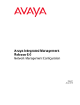
2.1
Configure IP Trunks
When installing a VoIP daughter board in the NEC SL1100 system, external line
ports are allotted in accordance with the number of Licensed ports for the
particular IP Application.
The NEC SL1100 system now has the required information about the remote
destinations and the SIP configuration is complete. The only remaining task is
to configure F-Route to route calls to remote destinations via the IP trunks.
F-Route configuration is discussed in detail in the Automatic Route Selection
(ARS) feature in the NEC SL1100 Programming Manual.
Figure 3-1 Example of SL1100 IP Network Configuration
3-2
IP Networking
General IP Configuration
4
Enhancements
SECTION 1
INTRODUCTION
The NEC SL1100 system uses IP for various applications, including:
System Programming
Voice Over IP
This section describes the procedure for connecting the NEC SL1100
system to an existing data network and configuring TCP/IP. This is the first
step in implementing VoIP and other IP applications.
Networking Manual
General IP Configuration
With SL1100 Version 1200 (V1.20) and VoIP daughter board installed,
half duplex connections are not supported. For troubleshooting
purposes, a managed switch capable of port mirroring is required to
capture packet data from the SL1100 VoIPDB Ethernet port.
4-1
Issue 4.0
SECTION 2
NEC SL1100
NETWORK ADDRESSING OVERVIEW
Before connecting the system to a data network, it is necessary to obtain the relevant
IP Addressing information. This information is supplied by the IT Manager or Network
Administrator at the customer site.
2.1
IP Address
All equipment/devices used in the LAN setup must have an IP address
assignment. An IP address assigns a unique address for each device. There
are two types of IP addresses: Private and Global. A Private IP address is not
accessible through the internet; a Global IP address can be accessed through
the internet.
In most cases, a Private address is used, as LAN devices are not usually
directly connected to the internet. Private addresses are usually taken from
the following ranges:
Class A 10.0.0.0 ~ 10.22.255.255
Class B 172.16.0.0. ~ 172.31.255.255
Class C 192.168.0.0 ~ 192.168.255.255
A Public address is normally only used when a device is directly connected to
the internet. This is unlikely in the case of the equipment. If Public addressing
is used, the numbers are normally allocated by an ISP.
2.2
Subnet Mask
As the IP address includes information to identify both the network and the
final destination, the Subnet Mask sets apart the network and destination
information. The default subnet masks are:
Class A 255.0.0.0
Class B 255.255.0.0
Class C 255.255.255.0
The Subnet Mask is made up of four groups of numbers. When a group
contains the number 255, the router ignores or masks that group of numbers
in the IP address as it is defining the network location of the final destination.
4-2
General IP Configuration
NEC SL1100
Issue 4.0
For example, if the IP address is: 172.16.0.10 and the Subnet Mask used is
Class B (255.255.0.0), the first two groups of numbers (172.16) are ignored
once they reach the proper network location. The next two groups (0.10) are
the final destination within the LAN to which the connection is to be made.
2.3
For sub-netted networks, the subnet mask may be different from the
default subnet masks listed above.
DHCP
Dynamic Host Configuration Protocol (DHCP) assigns a dynamic IP address.
Network control may be easier with DHCP as there is no need to assign and
program individual IP addresses for the LAN equipment. To use a dynamic IP
address, a DHCP server must be provided. The SL1100 can be configured to
be the DHCP server for the customers network. Before the DHCP server in
the SL1100 can be enabled, the DHCP client function must first be disabled.
When equipment, which is connected to the LAN (the DHCP client), is
requesting an IP address, it searches the DHCP server.
When the request for an address is recognized, the DHCP server assigns an
IP address, Subnet mask, and the IP address of the router, based on NEC
SL1100 system programming.
SECTION 3
CONFIGURATION EXAMPLES
The following configuration examples illustrate a typical network configuration for an
existing network that uses a static address and a typical configuration for a new
network that uses a dynamic address.
3.1
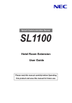
Example Configuration 1 - Existing Network with Static
Addressing
Figure 4-1 Example Configuration 1 - Existing Network with Static IP Address
on page 4-4 shows a typical network configuration that uses Static IP
Addressing.
Each client device has a manually assigned IP address in the 192.168.1.0/24
network (i.e., 192.168.1.1 to 192.168.1.254 with a subnet mask of
255.255.255.0). They also have a default gateway address configured
(192.168.1.254) this allows the device to route packets to destinations that
exist outside of their own LAN.
Networking Manual
4-3
Issue 4.0
NEC SL1100
WAN,
Internet, etc.
Router
(Default Gateway)
192.168.1.254
Switch
192.168.10.11
192.168.1.50
192.168.1.10
192.168.1.32
Figure 4-1 Example Configuration 1 - Existing Network with Static IP Address
Assume that a NEC SL1100 is added to the existing data network. The
Network Administrator (or IT Manager) should provide the following:
IP Address (for the CPU-B1)
IP Addresses (for the VoIP daughter board)
Subnet Mask
Default Gateway
A spare switch
First, program the NEC SL1100:
192.168.1.200
255.255.255.0
PRG10-12-03: 192.168.1.254
4-4
A system reset is required for the IP Address changes to take effect.
General IP Configuration
NEC SL1100
Issue 4.0
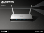
Now connect the CPU-B1/VoIPDB Ethernet Port to the switch port, using a
standard Cat-5 patch cable. The NEC SL1100 is now configured on the
network and should be accessible by other devices on the network. Refer to
Figure 4-2 Example Configuration 1 - Adding the NEC SL1100 KSU to the
Network.
WAN,
Internet, etc.
NEC SL1100 KSU
with CPU Installed
Router
(Default Gateway)
192.168.1.254
Switch
192.168.1.200
192.168.10.11
192.168.1.50
192.168.1.10
192.168.1.32
Figure 4-2 Example Configuration 1 - Adding the NEC SL1100 KSU to the Network
Networking Manual
4-5
Issue 4.0
SECTION 4
NEC SL1100
TESTING THE NEC SL1100 NETWORK CONNECTION
To test the NEC SL1100 network connection, it is possible to use the ICMP (Internet
Control Message Protocol) Ping command. This basically sends a small amount of
data from one device to another and then waits for a reply. This test confirms that the
IP addressing and physical connection are good. To perform this test, from a
Windows PC:
1.
Click Start.
2.
Click Run... .
3.
In the Open dialogue box, enter command.
4.
Click OK. A Command prompt window opens.
5.
Type ping 192.168.1.200.
Figure 4-3 Testing the Network Connection shows that the NEC SL1100 system has
replied to the Ping request – this indicates that the NEC SL1100 system is correctly
connected to the network.
Figure 4-3 Testing the Network Connection
4-6
General IP Configuration
Programming
SECTION 1
5
BEFORE YOU START PROGRAMMING
When using this chapter, note that the information on each program is
subdivided into the following headings:
Description describes what the program options control. The Default
Settings for each program are also included. When you first install the
system, it uses the Default Setting for all programs. Along with the
Description are the Conditions which describe any limit or special
consideration that may applies to the program.
Programming
This chapter provides you with detailed information about the NEC SL1100
program blocks that may be required to connect the NEC SL1100 to a data
network and to configure the VoIP function. The configuration and
programming examples, found in the earlier chapters, can be a useful
reference when programming the data.
The reverse type (white on black) just beneath the Description heading is
the program access level. You can use only the program if your access
level meets or exceeds the level the program requires. Refer to Section 2
How to Enter Programming Mode on page 5-2 for a list of the system
access levels and passwords.
Feature Cross Reference provides you with a table of all the features
affected by the program. You should keep the referenced features in mind
when you change a program. Customizing a feature may have an effect on
another feature that you did not intend.
Networking Manual
5-1
Issue 4.0
NEC SL1100
Telephone Programming Instructions shows how to enter the program data into
system memory. For example:
To enter the programming mode:
1.
15-07-01
15-07-01 TEL
KY01 = *01
Dial 150701 from the telephone dial pad. See the message 15-07-01 TEL on the
first line of the telephone display. This indicates the program number (15-07),
item number (01), and that the options are being set for the extension.
The second row of the display KY01 = *01 indicates that Key 01 is being
programmed with the entry of *01. The third row allows you to move the cursor to
the left or right, depending on which arrow is pressed.
To learn how to enter the programming mode, refer to Section 2 How to Enter
Programming Mode below.
SECTION 2
HOW TO ENTER PROGRAMMING MODE
To enter programming mode:
1.
Go to any working display telephone.
In a newly installed system, use extension (port 1).
2.
Do not lift the handset.
3.
Press Speaker.
4.
##.
Password
5-2
Programming
NEC SL1100
Issue 4.0
5.
Dial the system password + Hold.
Refer to the following table for the default system passwords. To change the
passwords, use 90-02: Programming Password Setup.
SECTION 3
Password
User
Name
Level
12345678
sltech
2 (IN)
Installation(IN): All programs in this section not listed
for MF, SA, and SB
0000
ADMIN1
3 (SA)
System Administrator - Level 1 (SA):
10-01,10-02,10-12,10-13,10-14,10-15,10-16,10-17,1018,10-23,10-24,10-25,10-28,10-29,10-45,12-02,1203,12-04,12-08,15-01,15-07,15-09,15-10,15-11,2016,20-34,21-07,21-14,22-04,22-11,22-17,25-08,3003,30-04,32-02,45-02,84-22,90-03,90-04,90-06,9007,90-19,90-57,90-58,90-59,90-65
9999
ADMIN2
4 (SB)
System Administrator - Level 2 (SB):
13-04, 13-05, 13-06, 13-11, 15-14, 21-20
Programs at this Level
HOW TO EXIT PROGRAMMING MODE
To exit the programming mode:
To exit programming mode, first exit the programming options mode.
1.
Press Mute to exit program options, if needed.
Program Mode
Base Service OP1 OP2
2.
Press Speaker. If changes were made to the system programming, Saving
System Data is displayed.
3.
When completed, the display shows Complete Data Save and exits the
telephone to idle.
Networking Manual
To save a customer database, a blank Compact Flash (CF) is required.
Insert the CF into the CD-CP00-US and, using Program 90-03, save the
software to the Compact Flash. (Program 90-04 is used to reload the
customer data if necessary.) Note that a Compact Flash can hold only one
customer database. Each database to be saved requires a separate card.
5-3
Issue 4.0
SECTION 4
NEC SL1100
USING KEYS TO MOVE AROUND IN THE PROGRAMS
Once you enter the programming mode, use the keys in the following chart to enter
data, edit data and move around in the menus.
Table 5-1 Keys for Entering Data
Keys for Entering Data
5-4
Use this key...
When you want to...
0~9 and
Enter data into a program.
Hold
Complete the programming step you just made (e.g., pressing Enter on
a PC keyboard). When a program entry displays, press Hold to bypass
the entry without changing it.
Clear/Back
Delete the entry to the left (e.g., pressing Backspace on a PC keyboard).
Flash
Delete or clear all characters to the right of the cursor.
Mute
Exit one step at a time from the program window currently being viewed.
For example, if programming item 5 in 15-03, pressing Mute allows you
to enter a new option in program 15-03. Pressing Mute again allows you
to select a new program in the 15-XX series. Pressing Mute a third time
allows you to enter a new program beginning with 1. Pressing Mute one
last time brings you to the beginning program display, allowing you to
enter any program number.
DND
Switch between the different input data fields by pressing DND. The
cursor moves up to the top row of the display. Pressing DND again
moves the cursor back to the middle row.
Line Keys
Use pre-programmed settings to help with the program entry. These
settings vary between programs from LINE 1 = 0 (off) and LINE 2 = 1
(on) to preset values for timers where LINE 1 = 5, LINE 2 = 10, LINE 3 =
15, etc.
For programs with this option, the line key, which currently matches the
programmed setting, lights steady.
The display can also indicate Softkey, which will allow you to select the
values as well (-1 and +1 will step through these pre-programmed
settings.)
Line Key 1
Program a pause into a Speed Dialing bin.
Line Key 2
Program a recall/flash into a Speed Dialing bin.
Line Key 3
Program an @ into a Speed Dialing bin.
VOL
Scroll backward through a list of entry numbers (e.g., from extension
etc.) or through entries in a table (e.g., Common Permit Table).
If you enter data and then press this key, the system accepts the data
before scrolling forward.
Programming
NEC SL1100
Issue 4.0
Table 5-1 Keys for Entering Data (Continued)
Keys for Entering Data
SECTION 5
Use this key...
When you want to...
VOL
Scroll forward through a list of entry numbers (e.g., from extension etc.)
or through entries in a table (e.g., Common Permit Table).
If you enter data and then press this key, the system accepts the data
before scrolling backward.
PROGRAMMING NAMES AND TEXT MESSAGES
Several programs (e.g., Program 20-16 : Selectable Display Messages) require you
to enter text. Use the following chart when entering and editing text. When using the
keypad digits, press the key once for the first character, twice for the second
character, etc. For example, to enter a C, press the key 2 three times. Press the key
six times to display the lower case letter. The name can be up to 12 digits long.
Table 5-2 Keys for Entering Names
Use this keypad digit . . .
1
When you want to. . .
Enter characters:
Æ ¨
1 @ [ ¥ ] ^ _ ` { | }
2
Enter characters: A-C, a-c, 2.
3
Enter characters: D-F, d-f, 3.
4
Enter characters: G-I, g-i, 4.
5
Enter characters: J-L, j-l, 5.
6
Enter characters: M-O, m-o, 6.
7
Enter characters: P-S, p-s, 7.
8
Enter characters: T-V, t-v, 8.
9
Enter characters: W-Z, w-z, 9.
0
Enter characters:
0
#
Networking Manual
Á À Â Ã Ç É Ê ì ó
!
“
#
$
%
Enter characters:
+ , - . /
&
:
’
;
(
<
) ô Õ ú ä ö ü
=
>
? B E
S • ¢ £
# = Accepts an entry (only required if two letters on the same
key are needed - ex: TOM). Pressing # again = Space. (In
system programming mode, use the right arrow Softkey
instead to accept and/or add a space.)
5-5
Issue 4.0
NEC SL1100
Table 5-2 Keys for Entering Names
Use this keypad digit . . .
When you want to. . .
Clear/Back
Clear the character entry one character at a time.
Flash
SECTION 6
Clear all the entries from the point of the flashing cursor and to
the right.
USING SOFTKEYS FOR PROGRAMMING
Each NEC SL1100 display telephone provides interactive Softkeys for intuitive feature
access. The options for these keys will automatically change depending on where you
are in the system programming. Simply press the Softkey located below the option
you wish and the display will change accordingly.
_
Base
Program Mode
Service
OP1
OP2
Pressing the VOLUME or VOLUME will scroll between the menus.
5-6
Programming
NEC SL1100
SECTION 7
Issue 4.0
WHAT THE SOFTKEY DISPLAY PROMPTS MEAN
When using a display telephone in programming mode, various Softkey options are
displayed. These keys will allow you to easily select, scan, or move through the
programs.
Table 5-3 Softkey Display Prompts
Softkey Display Prompts
If you press this
Softkey . . .
back
Go back one step in the program display.
You can press VOLUME or VOLUME to scroll forward or
backward through a list of programs.
Scroll down through the available programs.
Scroll up through the available programs.
select
SECTION 8
The system will. . .
Select the currently displayed program.
Move the cursor to the left.
Move the cursor to the right.
-1
Move back through the available program options.
+1
Move forward through the available program options.
PROGRAMS
This sections describes the programs used to connect the NEC SL1100 to a data
network and to configure the VoIP functions.
Networking Manual
5-7
Issue 4.0
NEC SL1100
Program 10 : System Configuration Setup
10-12 : CPU Network Setup
Level:
SA
Description
Use Program 10-12 : CPU Network Setup to setup the IP Address, Subnet-Mask,
and Default Gateway addresses.
Caution! If any IP Address or NIC settings are changed, the system must be
reset for the changes to take affect.
Input Data
Item
No.
Item
01
IP Address
Input Data
Default
0.0.0.0 ~ 126.255.255.254
Description
192.168.0.10
Set for CPU.
255.255.255.0
The setting of Subnet
Mask is invalid when
all Host Addresses
are 0.
128.0.0.1 ~ 191.254.255.254
192.0.0.1 ~ 223.255.255.254
02
Subnet
Mask
128.0.0.0
192.0.0.0
224.0.0.0
240.0.0.0
248.0.0.0
252.0.0.0
254.0.0.0
255.0.0.0
255.128.0.0
255.192.0.0
255.224.0.0
255.240.0.0
255.248.0.0
255.252.0.0
255.254.0.0
255.255.0.0
255.255.128.0
255.255.192.0
255.255.224.0
255.255.240.0
255.255.248.0
255.255.252.0
255.255.254.0
255.255.255.0
255.255.255.128
255.255.255.192
255.255.255.224
128.0,
255.255.255.240
255.255.255.248
255.255.255.252
191.255,
255.255.255.254
255.255.255.255
If the network section
is:
0,
127,
192.0.0,
223.255.255
The setting of Subnet
Mask is invalid.
03
Default
Gateway
0.0.0.0 ~ 126.255.255.254
0.0.0.0
IP Address for Router.
128.0.0.1 ~ 191.254.255.254
192.0.0.1 ~ 223.255.255.254
5-8
Programming
NEC SL1100
Issue 4.0
Input Data (Continued)
Item
No.
Item
04
Time Zone
05
NIC
Interface
Input Data
0~24 (0 = -12 Hours and 24 = +12 Hours)
0 = Auto Detect
Default
Description
+7
(-5 hours)
Determine the offset
from Greenwich Mean
Time (GMT) time.
Then enter its
respective value. For
example, Eastern
Time (US and
Canada) has a GMT
offset of -5. The
program data would
then be 7 (0= -12, 1=
-11, 2= -10, 3= -9, 4=
-8, 5= -7, 6= -6,
7= -5, ……24= +12)
0
1 = 100Mbps, Full-Duplex
NIC Auto Negotiate
(CPU)
2 = 100Mbps, Half-Duplex
3 = 10Mbps, Full-Duplex
4 = 10Mbps, Half-Duplex
06
07
08
09
NAT Router
Setup
0 = No (Disable)
NAPT
Router IP
Address
(Default
Gateway
[WAN])
0.0.0.0 ~ 126.255.255.254
ICMP
Redirect
0= (Enable)
IP Address
0.0.0.0 ~ 126.255.255.254
0
1 = Yes (Enable)
If using an external
NAT Router or not.
0.0.0.0
Set the IP address on
the WAN side of
router.
0
When receiving ICMP
redirect message, this
determines if the IP
Routing Table
updates automatically
or not.
128.0.0.1 ~ 191.255.255.254
192.0.0.1 ~ 223.255.255.254
1= (Disable)
172.16.0.10
Set for VoIPDB.
128.0.0.1 ~ 191.255.255.254
192.0.0.1 ~ 223.255.255.254
Networking Manual
5-9
Issue 4.0
NEC SL1100
Input Data (Continued)
Item
No.
10
11
Item
Input Data
Subnet
Mask
NIC Setup
Default
128.0.0.0
192.0.0.0
224.0.0.0
240.0.0.0
248.0.0.0
252.0.0.0
254.0.0.0
255.0.0.0
255.128.0.0
255.192.0.0
255.224.0.0
255.240.0.0
255.248.0.0
255.252.0.0
255.254.0.0
255.255.0.0
255.255.128.0
255.255.192.0
255.255.224.0
255.255.240.0
255.255.248.0
255.255.252.0
255.255.254.0
255.255.255.0
255.255.255.128
255.255.255.192 255.255.255.224
255.255.255.240
255.255.255.248 255.255.255.252
255.255.255.254
255.255.255.255
0 = Auto Detect
Description
255.255.0.0
Set for VoIPDB.
0
Set for VoIPDB.
1 = 100Mbps, Full-Duplex
2 = 100Mbps, Half-Duplex
3 = 10Mbps, Full-Duplex
4 = 10Mbps, Half-Duplex
5 = 1 Gbps, Full-Duplex
6 = 1 Gbps, Half-Duplex
Conditions
The system must be reset for these changes to take affect.
Feature Cross Reference
5 - 10
Voice Over Internet Protocol (VoIP)
Programming
NEC SL1100
Issue 4.0
Program 10 : System Configuration Setup
10-13 : In-DHCP Server Setup
Level:
SA
Description
Use Program 10-13 : In-DHCP Server Setup to setup the DHCP Server built into the
CPU-B1 card.
Input Data
Item
No.
Item
Input Data
Default
Description
01
DHCP Server
Mode
0 = Disable
1 = Enable
0
Enable/Disable the built-in DHCP
Server.
02
Lease Time
Days 0~255
0 day
Lease Time of the IP address to a
client.
Hour 0~23
0 hour
Minutes 1~59
05
Last DHCP Data
0 = Disable
1 = Enable
Press Transfer to increment to
the next setting data.
30 minutes
1
If 10-13-01 is enabled, Enable/
Disable DHCP resource.
Conditions
Program 10-13-01 cannot be enabled if Program 10-63-01 (DHCP Client Mode) is
enabled.
Feature Cross Reference
Networking Manual
Voice Over Internet Protocol (VoIP)
5 - 11
Issue 4.0
NEC SL1100
Program 10 : System Configuration Setup
10-14 : Managed Network Setup
Level:
SA
Description
Use Program 10-14 : Managed Network Setup to set up the range of the IP address
which the DHCP Server leases to a client.
Item
No.
Item
01
The range of the IP address
to lease.
When Maximum has not been
entered, the maximum value
equals the minimum value.
Input Data
Minimum:
Default
Related
Program
172.16.0.100
1.0.0.1 ~ 126.255.255.254
128.1.0.1 ~ 191.254.255.254
192.0.1.1 ~ 223.255.254.254
When Single is selected in
10-13-04, only 1 scope range
can be entered.
Maximum:
When Divide Same Network is
selected in 10-13-04, a
maximum of 10 scope ranges
can be entered.
128.1.0.1 ~ 191.254.255.254
172.16.5.254
1.0.0.1 ~ 126.255.255.254
192.0.1.1 ~ 223.255.254.254
Conditions
None
Feature Cross Reference
5 - 12
Voice Over Internet Protocol (VoIP)
Programming
NEC SL1100
Issue 4.0
Program 10 : System Configuration Setup
10-15 : Client Information Setup
Level:
SA
Description
Use Program 10-15 : Client Information Setup to set up the client information when
the DHCP server needs to assign a fixed IP address to clients.
Input Data
Client Number
Item
No.
01
1~16
Item
The IP address should be
assigned out of the scope
range set up in Program 10-14.
Input Data
MAC: 00-00-00-00-00-00 ~
FF-FF-FF-FF-FF-FF
1.0.0.0 ~ 126.255.255.254
128.0.0.1 ~ 191.255.255.254
192.0.0.1 ~ 223.255.255.254
Default
00-00-00-00-00-00
0.0.0.0
Conditions
None
Feature Cross Reference
Networking Manual
Voice Over Internet Protocol (VoIP)
5 - 13
Issue 4.0
NEC SL1100
Program 10 : System Configuration Setup
10-16 : Option Information Setup
Level:
SA
Description
Use Program 10-16 : Option Information Setup to set up the option given from the
DHCP server to each client.
Input Data
Item
No.
01
Item
3 (Fixed)
IP address
0.0.0.0 ~ 126.255.255.254
128.0.0.1 ~ 191.255.255.254
192.0.0.1 ~ 223.255.255.254
0.0.0.0
Code number 0~255
6 (Fixed)
IP address
0.0.0.0 ~ 126.255.255.254
128.0.0.1 ~ 191.255.255.254
192.0.0.1 ~ 223.255.255.254
0.0.0.0
TFTP Server
Code number 0~255
66 (Fixed)
Set the name for the TFTP
Server.
Maximum 64 character strings
No setting
MGC
Code number 0~255
129 (Fixed)
IP address
0.0.0.0 ~ 126.255.255.254
128.0.0.1 ~ 191.255.255.254
192.0.0.1 ~ 223.255.255.254
172.16.0.10
Code number 0~255
12 (Fixed)
Maximum 64 character strings
No setting
Code number 0~255
15 (Fixed)
Maximum 20 character strings
No setting
DNS Server
Set IP address of DNS Server.
03
05
06
Client Host Name
Set the Client Host Name.
07
DNS Domain Name
Set the DNS Domain Name.
5 - 14
Default
Code number 0~255
Router
Set the Router IP address.
02
Input Data
Programming
NEC SL1100
Issue 4.0
Input Data (Continued)
Item
No.
08
09
10
11
12
13
14
16
Networking Manual
Item
Input Data
Default
Download Protocol
Code number 0~255
43 (Fixed)
Set Download Protocol used
for AutoConfig (for DT700
Series).
Sub code number
163
1 = FTP
2 = HTTP
1
Encryption Information
Code number 0~255
43 (Fixed)
Set an Encryption Information
used for AutoConfig (for DT700
series).
Sub code number
164
Maximum 128 character
strings
No setting
FTP Server Address
Code number 0~255
43 (Fixed)
Set a FTP Server Address
used for AutoConfig.
Sub code number
141
IP address
0.0.0.0 ~ 126.255.255.254
128.0.0.1 ~ 191.255.255.254
192.0.0.1 ~ 223.255.255.254
0.0.0.0
Config File Name
Code number 0~255
43 (Fixed)
Set a File Name used for
AutoConfig.
Sub code number
151
Maximum 15 character strings
No setting
Code number 0~255
60 (Fixed)
Maximum 256 character
strings
NECDT700
Code number 0~255
69 (Fixed)
IP address
0.0.0.0 ~ 126.255.255.254
128.0.0.1 ~ 191.255.255.254
192.0.0.1 ~ 223.255.255.254
0.0.0.0
Code number 0~255
70 (Fixed)
IP address
0.0.0.0 ~ 126.255.255.254
128.0.0.1 ~ 191.255.255.254
192.0.0.1 ~ 223.255.255.254
0.0.0.0
Code number 0~255
120 (Fixed)
IP address
0.0.0.0 ~ 126.255.255.254
128.0.0.1 ~ 191.255.255.254
192.0.0.1 ~ 223.255.255.254
172.16.0.10
Vender Class ID
SNMP Server
POP3 Server
SIP Server (IP Address)
5 - 15
Issue 4.0
NEC SL1100
Input Data (Continued)
Item
No.
Item
17
SIP Server (Domain Name)
18
19
20
21
22
23
24
27
5 - 16
FTP Server
Config File Name
LDS Server 1
LDS Server 2
LDS Server 3
LDS Server 4
Next Server IP Address
SIP Server Receive Port
Input Data
Default
Code number 0~255
120 (Fixed)
Maximum 20 character strings
No setting
Code number 0~255
141 (Fixed)
IP address
0.0.0.0 ~ 126.255.255.254
128.0.0.1 ~ 191.255.255.254
192.0.0.1 ~ 223.255.255.254
0.0.0.0
Code number 0~255
151 (Fixed)
Maximum 15 character strings
No setting
Code number 0~255
162 (Fixed)
IP address
0.0.0.0 ~ 126.255.255.254
128.0.0.1 ~ 191.255.255.254
192.0.0.1 ~ 223.255.255.254
0.0.0.0
Code number 0~255
162 (Fixed)
IP address
0.0.0.0 ~ 126.255.255.254
128.0.0.1 ~ 191.255.255.254
192.0.0.1 ~ 223.255.255.254
0.0.0.0
Code number 0~255
162 (Fixed)
IP address
0.0.0.0 ~ 126.255.255.254
128.0.0.1 ~ 191.255.255.254
192.0.0.1 ~ 223.255.255.254
0.0.0.0
Code number 0~255
162 (Fixed)
IP address
0.0.0.0 ~ 126.255.255.254
128.0.0.1 ~ 191.255.255.254
192.0.0.1 ~ 223.255.255.254
0.0.0.0
IP address
0.0.0.0 ~ 126.255.255.254
128.0.0.1 ~ 191.255.255.254
192.0.0.1 ~ 223.255.255.254
0.0.0.0
Code number 0~255
168 (Fixed)
Port: 1~65535
5080
Programming
NEC SL1100
Issue 4.0
Conditions
None
Feature Cross Reference
Networking Manual
Voice Over Internet Protocol (VoIP)
5 - 17
Issue 4.0
NEC SL1100
Program 10 : System Configuration Setup
10-19 : VoIP DSP Resource Selection
Level:
SA
Description
Use Program 10-19 : VoIP DSP Resource Selection to define the criteria for each
DSP resource on the VoIPDB card.
Input Data
Slot Number
0
DSP Resource Number
01~32
Input Data
Input Data
Item
No.
01
Item
VoIP DSP Resource Selection
Input Data
0 = Common use for both IP
extensions and trunks
1 = IP Extension
2 = SIP Trunk
3 = Blocked
4 = Common without Unicast
paging
5 = Multicast paging
6 = Unicast paging
Default
Resource 1 = 1
Resource 2~32 = 0
Conditions
None
Feature Cross Reference
5 - 18
None
Programming
NEC SL1100
Issue 4.0
Program 10 : System Configuration Setup
10-62 : NetBIOS Setting
Level:
IN
Description
Use Program 10-62 : NetBIOS Setting to enable or disable the SL1100 to use
NetBIOS for connection with PCPro and Web Pro
Input Data
Item
No.
Item
01
NetBIOS MODE
0 = Disabled
1 = Enabled
02
NetBIOS Name
Maximum 15 characters
Input Data
Default
Description
1
With NetBIOS enabled, a user
can connect to the SL1100 using
PCPro or Web Pro with the name
specified in Program 10-62-02.
SL1100
Enter this name in PCPro or Web
Pro to connect to the SL1100.
Conditions
Spaces cannot be included in a NetBIOS name.
Feature Cross Reference
Networking Manual
None
5 - 19
Issue 4.0
NEC SL1100
Program 10 : System Configuration Setup
10-63 : DHCP Client Setting
Level:
IN
Description
Use Program 10-63 : DHCP Client Setting to enable or disable the SL1100 to
receive its IP Addressing information from a DHCP server.
Input Data
Item
No.
Item
01
DHCP Client Mode
Input Data
0 = Disable
1 = Enable
Default
Description
1
If you are using IP Phones/IP
trunks it is recommended to not
use the DHCP Client function, a
static IP address is preferred. If
you are going to still use DHCP,
the DHCP server should be set up
so that the same IP address is
always provided to the SL1100.
If this program is changed a
system reset is required.
Conditions
This feature can not be enabled if Program 10-13-01 (DHCP Server) is enabled.
Feature Cross Reference
5 - 20
None
Programming
NEC SL1100
Issue 4.0
Program 20 : System Option Setup
15-05 : IP Telephone Terminal Basic Data Setup
Level:
IN
Description
Use Program 15-05 : IP Telephone Terminal Basic Data Setup to set up the basic
settings for an IP telephone.
Input Data
Extension Number
Item
No.
Item
Input Data
01
Terminal Type
0
1
2
3
4
02
Terminal MAC
Address
MAC address
00-00-00-00-00-00 to
FF-FF-FF-FF-FF-FF
04
Nickname
Up to 48 characters
07
Using IP
Address
0.0.0.0~255.255.255.255
09
Call Procedure
Port
0~65535
15
CODEC Type
1-Type 1
2-Type 2
3-Type 3
4-Type 4
5-Type 5
16
Authentication
Password
Up to 24 characters
Networking Manual
= NGT
= H.323
= SIP
= MEGACO
= SIP-MLT
Maximum eight digits
Default
Description
0
Viewing Only – No changes
permitted
00-00-00-00-00-00
MAC Address of registered
MLT SIP phone is stored
and/or can input the MAC
address of an MLT SIP
phone so when it comes
online it will be provided with
the extension in which the
MAC address matches.
No setting
Nickname section on Invite
message.
0.0.0.0
Informational Only
Related
Program
15-05-01
15-05-01
registered IP Phones
15-05-01
1
Assign the CODEC Type of
the MLT SIP.
84-24-XX
None
Assign the authentication
password for SIP single line
telephones.
15-05-01
5 - 21
Issue 4.0
NEC SL1100
Item
No.
Item
18
IP Duplication
Allowed Group
26
DR700
Terminal Type
Input Data
Related
Program
Default
Description
0 = Not Used
1 = Group 1
2 = Group 2
3 = Group 3
4 = Group 4
5 = Group 5
6 = Group 6
7 = Group 7
8 = Group 8
9 = Group 9
10 = Group 10
0
For an adapter with one IP
address coming into it but
multiple extensions off of it.
Assign all the extensions to
a group so that way the CPU
knows that the one IP
address is assigned to
multiple extensions.
15-05-01
1 = Not Used
0
Use when the SIP Multiline
telephone is using manual/
auto registration. Assign
each phone a unique
personal index. Then go to
command 84-22 to assign
the user name and
password.
84-22-XX
2 = ITL-**D-1D/ITL-24BT1D/
ITL- 24PA-1D [without
8LKI(LCD)-L]
3 = Not Used
4 = Not Used
5 = Softphone
6 = CTI
7 = Not Used
8 = Not Used
9 = IP4WW-24TXH-B TEL
27
Personal ID
Index
0~084
0
28
Addition
Information
Setup
0 = Disable
1 = Enable
0
Select whether
to inform of
additional
information or
not.
29
Terminal WANside IP
Address
0.0.0.0~255.255.255.255
30
DTMF play
during
conversation
at Receive
Extension
0 = Do Not Play
1 = Play
5 - 22
0.0.0.0
0
Programming
NEC SL1100
Item
No.
Issue 4.0
Item
Input Data
31
Alarm Tone
during
conversation
(RTP packet
loss alarm)
0 = Not Ringing
1 = Ringing
33
LAN Side IP
Address of
Terminal
0.0.0.0~255.255.255.255
35
Encryption
Mode On/Off
0 = Off
1 = On
36
DR700
Firmware
Version
00.00.00.00~FF.FF.FF.FF
38
Paging
Protocol Mode
39
Default
Description
1
0.0.0.0.
Read-only
0
00.00.00.00
Indicate a current firmware
version.
0 = Multcast
1 = Unicast
2 = Auto
0
Sets the protocol mode for
the Paging function.
CTI Override
Mode
0 = Disable
1 = Enable
0
40
Calling Name
Display Info via
Trunk for
Standard SIP
0 = Both name and
number
1 = Name only
2 = Number only
3 = None
0
41
Time Zone
(Hour)
0~24
(-12 ~ +12 hour)
12
43
Video Mode
0 = Disable
1 = Enable
0
44
Using STD-SIP
Display for
CPN
0 = Disable
1 = Enable
0
45
NAT Plug &
Play
0 = Off
1 = On
1
Networking Manual
Related
Program
Effective when PRG
10-46-14 is set to NAT
mode. Select sending RTP
port number to remove
Router, use from negotiation
result (0), or received RTP
packet (1).
10-46-14
5 - 23
Issue 4.0
NEC SL1100
Conditions
15-05-04 – Nickname must be unique in the system.
Feature Cross Reference
None
5 - 24
Voice Over Internet Protocol (VoIP)
Programming
NEC SL1100
Issue 4.0
Program 84 : Hardware Setup for VoIP
84-09 : VLAN Setup
Level:
IN
Description
Use Program 84-09 : VLAN Setup to set up the VLAN data.
Input Data
Item
No.
Item
Input Data
Default
01
VLAN
0 = Disable (Off)
1 = Enable (On)
0
02
VLAN ID
1~4094
0
03
VLAN Priority
0~7
0
Conditions
System programming must be exited before these program options take affect.
Feature Cross Reference
Networking Manual
Voice Over Internet Protocol (VoIP)
5 - 25
Issue 4.0
NEC SL1100
Program 84 : Hardware Setup for VoIP
84-10 : ToS Setup
Level:
IN
Description
Use Program 84-10 : ToS Setup to set up the Type of Service data.
Input Data
Protocol Type
Item
No.
5 - 26
1 = Not Used
2 = Not Used
3 = Not Used
4 = H.323
5 = RTP/RTCP
6 = SIP
7 = Not Used
8 = SIP MLT
9 = SIP Trunk
10 = Not Used
Item
Input Data
Default
Description
01
ToS Mode
0 = Disable (Invalid)
1 = IP Precedence
2 = Diffserv
0
When Input Data is set to 1,
Item No. 07 is invalid.
When Data is set to 2, Item
No. 02 ~ 06 are invalid.
02
Priority, IP Precedence
0~7
0 = Low
7 = High
0
1 = Router queuing priority
03
Low Delay
0~1
0 = Normal Delay, Low
Delay
0
1 = Optimize for low delay
routing
04
Wideband
(Throughout)
0~1
0 = Normal Throughput
1 = High Throughput
0
1 = Optimize for high
bandwidth routing
05
High Reliability
0~1
0 = Normal Reliability
1 = Low Reliability
0
1 = Optimize for reliability
routing
07
Priority (D.S.C.P. Differentiated Services
Code Point)
0~63
0
DSCP (Differentiated
Services Code Point)
Programming
NEC SL1100
Issue 4.0
Conditions
The system must be reset for these program options to take affect.
Feature Cross Reference
Networking Manual
Voice Over Internet Protocol (VoIP)
5 - 27
Issue 4.0
NEC SL1100
Program 90 : Maintenance Program
90-23 : Deleting Registration of IP Telephones
Level:
IN
Description
(This program is available only via telephone programming and not through PC
Programming).
Use Program 90-23 : Deleting Registration of IP Telephones to delete the
registered IP telephone from the system.
Input Data
Extension Number
Item
No.
01
Item
Delete IP Telephone
This assignment removes the station number
association with the MAC address of the IP station.
Up to 8 digits
Input Data
[Delete?] : Dial 1 + press Hold
(Press Hold to cancel.)
Conditions
None
Feature Cross Reference
5 - 28
Voice Over Internet Protocol (VoIP)
Programming
NEC SL1100
Issue 4.0
Program 90 : Maintenance Program
90-34 : Firmware Information
Level:
IN
Description
Use Program 90-34 : Firmware Information to list the package type and firmware
cards installed in the system.
Input Data
Slot No.
Item
No.
0~9
Item
Display Data
01
Pkg Name
PKG Name
02
Firmware Version Number
00.00~0F.FF
03
VOIPDB Software Version
00.00.00.00.00.00~
FF.FF.FF.FF.FF.FF
04
DSP Project Number
05
Vocallo Firmware Version
00.00.00.00~FF.FF.FF.FF
06
OCT1010ID Version
00.00.00.00~FF.FF.FF.FF
00000000~FFFFFFFF
Conditions
These Programs are ‘Read Only.’
Feature Cross Reference
None
Networking Manual
5 - 29
Issue 4.0
NEC SL1100
THIS PAGE INTENTIONALLY LEFT BLANK
5 - 30
Programming
Network Design Considerations
SECTION 1
INTRODUCTION
QOS
Quality of Service (QoS) is one of the most important factors for VoIP.
This refers to the perceived quality of speech and the methods used to
provide good quality speech transmission. Several factors that affect
speech quality and several mechanisms can be used to ensure QoS.
This chapter also describes the problems that can occur and some
possible solutions. Each network equipment manufacturer (NEC, 3Com,
Cisco, etc.) has slightly different methods of implementing QoS and these
are not discussed in this document. This chapter provides an overview to
classify voice traffic on the NEC SL1100 so that the network equipment
can impose QoS.
2.1
QoS Definitions
Network Design Considerations
This chapter explains some issues that should be considered when
planning a NEC SL1100 VoIP installation. This is a generalized
explanation and therefore does not discuss vendor-specific issues and
solutions. Typically, different solutions are implemented by different
manufacturers.
SECTION 2
6
This section lists common definitions used with QoS for VoIP.
Latency (Delay):
If at any point the usage on the network exceeds the available
bandwidth, the user experiences delay, also called latency. In more
traditional uses of an IP data network, the applications can deal with
this latency. If a person is waiting for a web page to download, they
can accept a certain amount of wait time. This is not so for voice
traffic. Voice is a real time application, which is sensitive to latency. If
the end-to-end voice latency becomes too long (150ms, for example),
Networking Manual
6-1
Issue 4.0
NEC SL1100
the call quality is usually considered poor. It is also important to remember that
packets can get lost. IP is a best effort networking protocol. This means the
network tries to get the information there, but there is no guarantee.
Delay is the time required for a signal to traverse the network. In a telephony
context, end-to-end delay is the time required for a signal generated at the talker's
mouth to reach the listener's ear. Therefore, end-to-end delay is the sum of all the
delays at the different network devices and across the network links through
which voice traffic passes. Many factors contribute to end-to-end delay, which are
covered next.
The buffering, queuing, and switching or routing delay of IP routers primarily
determines IP network delay. Specifically, IP network delay is comprised of the
following:
Packet Capture Delay
Packet capture delay is the time required to receive the entire packet
before processing and forwarding it through the router. This delay is
determined by the packet length and transmission speed. Using short
packets over high-speed networks can easily shorten the delay but
potentially decrease network efficiency.
Switching/Routing Delay
Switching/routing delay is the time the router takes to switch the packet.
This time is needed to analyze the packet header, check the routing
table, and route the packet to the output port. This delay depends on the
architecture of the switches/routers and the size of the routing table.
Queuing Time
Due to the statistical multiplexing nature of IP networks and to the
asynchronous nature of packet arrivals, some queuing, thus delay, is
required at the input and output ports of a packet switch. This delay is a
function of the traffic load on a packet switch, the length of the packets
and the statistical distribution over the ports. Designing very large router
and link capacities can reduce but not completely eliminate this delay.
Jitter
Delay variation is the difference in delay exhibited by different packets that are
part of the same traffic flow. High frequency delay variation is known as jitter. Jitter
is caused primarily by differences in queue wait times for consecutive packets in a
flow, and is the most significant issue for QoS. Certain traffic types, especially
real-time traffic such as voice, are very intolerant of jitter. Differences in packet
arrival times cause choppiness in the voice.
All transport systems exhibit some jitter. As long as jitter falls within defined
tolerances, it does not impact service quality. Excessive jitter can be overcome by
buffering, but this increases delay, which can cause other problems. With
intelligent discard mechanisms, IP telephony/VoIP systems try to synchronize a
communication flow by selective packet discard, in an effort to avoid the
6-2
Network Design Considerations
NEC SL1100
Issue 4.0
walkie-talkie phenomenon caused when two sides of a conversation have
significant latency. NEC SL1100 incorporates a Jitter Buffer to avoid these
problems.
Packet Loss
During a voice transmission, loss of multiple bits or packets of stream may cause
an audible pop that can become annoying to the user. In a data transmission, loss
of a single bit or multiple packets of information is almost never noticed by users.
If packet drops become epidemic, the quality of all transmissions degrades.
Packet loss rate must be less than five percent for minimum quality and less than
one percent for toll quality.
2.2
Voice Quality Improvements
This section describes various techniques that can be used to improve the
voice quality.
Increase available bandwidth:
This can sometimes be the most basic solution and the easiest of the
solutions. If running a System IP Phone using G.711 with a 30ms fill time
over Ethernet, for only one call, 90Kbps of bandwidth is needed. If that
same user only has a 64K line, they do not have a decent IP voice call.
The user can increase the available bandwidth to slightly exceed the
90Kbps requirements and their voice quality dramatically increases. This
solution might not be viable if no more bandwidth is available.
Use a different CODEC:
The CODEC contains possible compression algorithms to be used on
the voice. Let’s take the example above again. The user only wants one
voice line over a 64Kbps data connection. They also want to maintain
their current fill time of 30ms. Change to a G.729. For one line, only
34Kbps is required for a call. This fits well within the 64Kbps of available
bandwidth.
Increase the number of frames per packet:
To continue with the example above, the user has moved to a G.729
CODEC. But now, the user wishes to add two more System IP Phones.
Their current 64Kbps line can handle one call, because it is only 34Kbps.
Two more System IP Phones would increase the total to 102Kbps so
obviously there is not sufficient bandwidth.
The user can now increase the fill time to 50ms. This reduces the bandwidth
per call to 19.8Kbps (3x 19.8 = 59.4Kbps). The savings in bandwidth comes
from the fact that with a longer fill time, fewer packets are needed to send
the voice. With fewer packets, less header information needs to be attached
and transmitted.
Networking Manual
6-3
Issue 4.0
NEC SL1100
Change Layer 2 Protocols:
Ethernet is most commonly used for IP packets. Unfortunately, Ethernet
has a fairly large overhead of 34 bytes. So every IP voice packet going
over Ethernet has a 34-byte Ethernet header attached to it. As the
number of packets add up, this header data can become significant.
Frame Relay has a 7-byte header and Point-to-Point Protocol (PPP) has
a 6-byte header. With this decrease in header length at layer 2, some
significant savings in bandwidth use can be achieved.
The down side to this is that most networks may not have these services
available, where Ethernet is very widely used. This is usually outside the
control of the installer and therefore NEC strongly advises users to do more
research on other layer 2 protocols before trying to implement them in their
voice network.
Implement Quality of Service (QOS):
Now, assume a derivative of the above example. The user needs only
one voice line over their 64Kbps connection. They are using G.729 with
a 30ms fill time. This requires 34Kbps of their available bandwidth. Also
assume that this line is used at certain times of the day for data
connectivity. This data connectivity is very light, only 20Kbps or so
during most of the day, but does spike to 50Kbps during certain points of
the day. This data is not time sensitive like the voice data, so if
necessary it could be forced to wait.
Therefore, the user can implement a Quality of Service mechanism on the
IP network. At its most basic form, this denotes certain IP packets as being
more important than others. So they would tell this 64Kbps line that IP
packets with voice deserve a higher priority than those without voice. This
allows the network devices to give priority to the other data, so the quality of
the call is not compromised.
2.3
Types of Classifications for Traffic for QoS
Classification uses information from a packet (or frame) to define the type of
data and therefore how the data should be handled for QoS on the network.
Using packet classification, you can partition network traffic into multiple
priority levels or Types of Service (ToS). NEC SL1100 supports methods of
marking a packet with its classification information in the Layer 2 or 3 headers.
6-4
VLAN (802.1Q):
Virtual LANs work at Layer 2 of the OSI model and can be equated to a
broadcast domain. More specifically, VLANs can be seen as a group of
end stations, perhaps on multiple physical LAN segments that are not
constrained by their physical location and therefore, communicate as if
they were on a common LAN. Packets can be marked as important by
Network Design Considerations
NEC SL1100
Issue 4.0
using layer 2 classes of service (CoS) settings in the User Priority bits of
the 802.1Pq header. Refer to Program 84-09 : VLAN Setup on page
5-30 for information for VLAN configuration.
Layer 2
802.1Q/p
PREAM
SFD
DA
SA
PRI
Type
TAG
4 Bytes
CFI
PT
Data
FCS
VLAN ID
Three bits used for CoS
(user priority)
Figure 6-1 Layer 2 Diagram (802.1Q)
Networking Manual
IP Precedence - Layer 3 QoS:
Allows you to specify the class of service for a packet. You use the three
precedence bits in the IPv4 header type of service (ToS) field for this
purpose. Using the ToS bits, you can define up to six classes of service.
Other devices configured throughout the network can then use these bits
to determine how to treat the packet in regard to the type of service to
grant it. These other QoS features can assign appropriate
traffic-handling policies including congestion management and
bandwidth allocation. By setting IP Precedence levels on incoming traffic
and using them in combination with QoS queuing features, you can
create differentiated service. (Refer to Program 84-10 : ToS Setup on
page 5-31 for detailed programming information.)
Differentiated service (Diffserv) - Layer 3 QoS:
Provides services differentiated on performance using weighted priority
queuing. DiffServ requires that edge routers classify traffic flows into a
member from a set of categories based on the TCP/IP header fields in
what is called a micro flow. Because the Diffserv is present in every
packet header, each node can provide differentiated services per-hop.
Refer to Program 84-10 : ToS Setup on page 5-31 for detailed
programming information.
6-5
Issue 4.0
SECTION 3
NEC SL1100
INTERNET BASED CONNECTIONS (XDSL, CABLE, ETC.)
Internet-based connections are becoming increasingly popular. This is mainly due to
the speed and cost of xDSL and cable modem connections. For data applications,
these types of connection are generally acceptable. For Voice over IP applications
several issues should be taken into consideration.
Asymmetric Data Rates
On many internet based connections, there are different data rates for upstream and
downstream. For example 1Mbps down and 256Kbps up. This works well for internet
access, as generally you download files from the internet to your PC and transmit less
information in the other direction. For VoIP, speech uses the same amount of
bandwidth in both directions, which means that the amount of simultaneous calls can
not exceed the amount of “upstream” bandwidth available.
Contention
Most internet based connections specify a contention ratio. This is typically 50:1 for
home users or 20:1 for business users. This specifies the number of users
subscribed to a single connection to the Internet Service Provider (ISP). This
indicates how many users share the bandwidth with other users on the internet, which
means that the speeds that you are quoted are not necessarily accurate – you receive
less than these figures.
It is unlikely that all subscribers are using a connection at the same time, so these figures are
not quite as bad as they first seem.
Network Address Translation (NAT)
Usually, the equipment that your ISP provides (cable modem, ADSL router, etc.) uses
Network Address Translation. This allows several devices to share one public IP
address. The issues relating to the use of NAT are outlined in Firewalls and NAT
below.
VPN
Due to the use of NAT, and non-routable IP addressing, it may be necessary to
implement a VPN solution. This is outlined in VPN Tunneling below. (Refer to 4.3
Virtual Private Network (VPN) Tunnelling on page 6-9.)
QoS
As discussed earlier, it is essential to have some form of Quality of Service
implemented. With internet based connections, we are not in control of the many
routers, switches and other network hardware that reside between our two VoIP
endpoints. This means that we cannot specify any QoS parameter on these devices.
6-6
Network Design Considerations
NEC SL1100
Issue 4.0
The only point where the QoS can be controlled is at the VPN or firewall. This allows
VoIP traffic to be prioritized over any other data that is sent out to the internet. This
helps to maintain reasonable quality speech – but once the data has exited the local
router/cable modem it is at the mercy of the internet.
When implementing NEC SL1100 IP over internet based connections it is very
important that these factors are considered, and that the customer is made aware that
neither the installer nor NEC are held responsible for any quality issues experienced.
SECTION 4
FIREWALLS AND NAT
The ways in which networks are designed to be secure (firewall, VPN services, proxy
servers, etc.) and integration of NAT create problems for VoIP. This is due in part, to
the endless number of different scenarios for non-real time protocols and their limited
solutions.
4.1
Understanding the Infrastructure
The networks in place today look very different than the networks of
yesterday. In the past, only computers and servers were connected to the
network. The network was built to be as a best effort delivery mechanism,
where delay and lost of information between devices was something we dealt
with. Today, there is an over saturation of devices needing to gain access to
the IP network. Desktop computers, fax machines, wireless PDAs, Servers,
home appliances, video servers and now VoIP terminals all are fighting for
bandwidth, precedence, and addresses on this converged network.
It is necessary to create some kind of Intranet environment (across the
Internet), with fixed network characteristics, where VoIP solutions can tolerate
some minor variations. IT personnel have been tasked with implementing
different mechanisms in the network to support the new demands required on
the converged network. Some solutions that have been implemented are:
Networking Manual
QoS devices to support precedence settings of voice packets.
Elimination of hubs in place of switches to support 100Mbps full-duplex
transmission.
Firewall integration to protect the internal network from external attack.
Network Address Translation (NAT) devices are widely deployed to
support the addressing issues.
Virtual Private Network (VPN) Servers were added to Enterprise
networks to support the security and connectivity issues for remote
users.
6-7
Issue 4.0
NEC SL1100
Some solutions, such as the hub replacement and integration of QoS, are
done behind the scenes and should have no effect on the voice application.
Other solutions such as NAT and Firewall cause major disturbance to VoIP.
4.2
Firewall Integration
Network security is always a concern when connecting the Local Area
Network (LAN) to the Wide Area Network (WAN). There are many ways to
integrate security in the network – the most popular are Firewalls and Proxy
servers.
Firewalls
Firewalls can be implemented in both hardware and software, or a
combination of both. Firewalls are frequently used to prevent
unauthorized Internet users from accessing private networks connected
to the Internet, especially intranets. All messages entering or leaving the
intranet pass through the firewall, which examines each message and
blocks those that do not meet the specified security criteria.
Proxy Server
Proxy server intercepts all messages entering and leaving the network.
The proxy server effectively hides the true network address.
What should be noted is that no matter which security measure is
implemented, the VoIP must have TCP/UDP ports open in the security wall
(e.g., firewall/proxy) for the media and control streams to flow. If any point in
the network prevents the ports from flowing from end-to-end, the VoIP
application does not work.
The ports that need to be open on the firewall/proxy vary depending on the
particular application being used. A list of these ports is shown below,
however it should be noted that the preferred solution would be to allow all
ports on the NEC SL1100 device to be open, or to place the NEC SL1100
outside of the firewall.
6-8
Applications
Rx Port
NEC SL1100
Programming
PC Programming
8000
90-54-02
Web Programming
80
90-54-01
DHCP Server
67
SIP MLT Listening Port
5080
5081
10-46-06
10-46-13
SIP Trunk Listening Port
5060
10-29-04
SIP Single Line Stations
5070
84-20-01
Realtime Transport Protocol
10020~10082
84-26-01
Network Design Considerations
NEC SL1100
Issue 4.0
4.3
Applications
Rx Port
NEC SL1100
Programming
Realtime Transport Control
Protocol (RTCP)
10021~10083
84-26-02
Virtual Private Network (VPN) Tunnelling
A Virtual Private Network is a private data network that maintains privacy
through using a tunneling protocol and security procedures. Allowing for
remote networks (including VoIP devices), which reside behind NATs and/or
Firewalls to communicate freely with each other.
The idea of the VPN is to connect multiple networks together using public (i.e.,
internet) based connections. This type of connection is ideal for those
commuters, home workers, or small branch offices needing connectivity into
the corporate backbone. It is possible to connect these remote networks
together using private links (such as leased lines, ISDN, etc.) but this can be
very expensive and there is now a high demand for low cost internet
connectivity.
Companies today are exploring the use of VPN for a variety of connectivity
solutions, such as:
Remote User to Corporate Site VPN
Allows employees to use their local ISP fastest connection such as cable
modems, DSL, and ISDN. For traveling users, all they need to do is dial
into their ISP local phone number.
Site-to-site VPN
Allows companies to make use of the Internet for the branch-to-branch
connections, cutting the cost of the expensive point to point leased line
service.
Extranet
Extranet describes one application using VPN technology. The concept
allows a company and a vendor/supplier to access network resources at
each site. For example, a customer may have access to a suppliers
intranet for access to product information.
VPNs can be implemented in hardware or software. Single users, such as
traveling sales personnel, may have a software based VPN client on their
laptop computer. This connects back to the Head Office VPN server. For
larger sites, the VPN is typically implemented using a hardware VPN – this is
often incorporated in to a firewall solution.
Networking Manual
6-9
Issue 4.0
NEC SL1100
The diagram below is example of how a VPN tunnel may be implemented.
The red lines in the diagram show the tunnels that are created through the
internet. Each network can connect to the others as though they are
connected with private connections (kilostream, etc.), without the issues
relating to NAT.
SL
AD
Internet
ADSL
Router
ADSL
Router
DSL / Cable / Dialup
Firewall/
VPN
AD
SL
Firewall/
VPN
Home Office LAN
SL1100
Head Office LAN
Mobile Workers
(Software VPN Client)
Figure 6-2 Virtual Private Network (VPN) Example
When IP address translation is applied to a VoIP packet, the application fails
and the communication path is broken. VoIP packets contain the IP address
information and the ports used as part of its payload. When NAT is applied,
only the header parameter is changed, not the payload data that affects the
process of data packets within the VoIP switch and terminal.
6 - 10
Network Design Considerations
NEC SL1100
Issue 4.0
The common scenario for remote IP deployment is:
Implementation of an IP Phone with a public IP address talking with an
NEC SL1100 behind NAT. An example would be a telecommuter.
Implementation of an IP Phone behind a NAT, which connects to the
internet, terminates in a NEC SL1100 behind a different NAT.
When selecting VPN equipment it is important to consider Quality of
Service. Generally, VPN hardware is connected to internet connections
which are unreliable and out of the control of the customer. However, it is
possible to set prioritization on some VPN units for voice traffic. This does
not solve the unreliability of the internet, but helps to ensure that the data
traffic to and from the LAN do not impair the quality of the voice traffic.
(Refer to Section 2 QoS on page 6-1).
SECTION 5
NEC strongly recommends that any VPN hardware used for VoIP has the
facility to prioritize voice traffic.
CODEC AND BANDWIDTH
This section describes CODEC and bandwidth and their application with the NEC
SL1100 system.
5.1
CODECs
CODEC (COder/DECoder) uses the technology of encoding and decoding a
signal. For VoIP, this specifically refers to the algorithm used to convert
analog speech to digital data for transmission on an IP network.
The NEC SL1100 system supports three different CODECs:
1.
G.711
This is the ITU-T recommendation for coding of speech at 64kbps using
PCM (pulse code modulation). This CODEC is often described as
uncompressed as it uses the same sampling rate as Time-Division
Multiplexing (TDM). G.711 has a MOS1 score of 4.2 but uses a large
bandwidth for transmission. This CODEC is not commonly used due to
the bandwidth required, although it can be acceptable in LAN
environment (i.e., IP Phones connected over a 100Mbps LAN).
G.722
G.722 is an ITU standard CODEC that provides 7kHz wideband audio at
data rates from 48 to 64kbps. This is useful in a fixed network Voice
Over IP applications, where the required bandwidth is typically not
The Mean Opinion Score (MOS) provides a numerical measure of the quality of human speech at the destination end
of the circuit. The scheme uses subjective tests (opinionated scores) that are mathematically averaged to obtain a
quantitative indicator of the system performance.
Networking Manual
6 - 11
Issue 4.0
NEC SL1100
prohibitive, and offers a significant improvement in speech quality over
older narrowband codecs such as G.711, without an excessive increase
in implementation complexity.
G.726
G.726 is an ITU-T ADPCM speech CODEC standard covering voice
transmission at rates of 16, 24, 32, and 40kbit/s. It was introduced to
supersede both G.721, which covered ADPCM at 32kbit/s, and G.723,
which described ADPCM for 24 and 40kbit/s. G.726 also introduced a
new 16kbit/s rate. The four bit rates associated with G.726 are often
referred to by the bit size of a sample as 2-bits, 3-bits, 4-bits, and 5-bits
respectively.
G.729A
This ITU-T recommendation describes the algorithm for coding of
speech signals at 8kbps using CS-ACELP (conjugate-structure algebraic
code-excited linear prediction). This CODEC samples the analog signal
at 8000Hz and uses a frame size of 10ms. This CODEC has a MOS
score of 4.0.
G.729 is the most commonly used CODEC for NEC SL1100 VoIP
installations. This is due to the fact that it offers high compression (and
therefore low bandwidth) while maintaining good speech quality.
G.723
This ITU-T recommendation describes a very low bit-rate compression
algorithm. The standard describes two versions 5.3Kbps and 6.4Kbps.
NEC SL1100 uses the higher bit rate. This CODEC offers low bandwidth
speech transmission, but has a lower MOS score of 3.9. This CODEC is
not commonly used on the NEC SL1100, but is particularly suited to low
bandwidth WAN connections.
iLBC
The iLBC CODEC is an algorithm that compresses each basic frame
(20ms or 30ms) of 8000 Hz, 16-bit sampled input speech, into output
frames with rate of 400 bits for 30ms basic frame size and 304 bits for
20ms basic frame size. This CODEC is suitable for real-time
communications such as, telephony and video conferencing, streaming
audio, archival and messaging.
Packet Size:
Each CODEC has a set frame length. This is the time that the frame
encapsulates. For G.729 and G.711 the frame length is 10ms and for G.723
the frame length is 30ms. It is possible to configure the packet size in the NEC
SL1100 programming. To do this, we tell the NEC SL1100 how many frames
to encapsulate into each packet for transmission.
For example, the G.729 has a frame length of 10ms - the packet size is set to
3 (in Program 84-11-01). This gives a 10ms x 3 = 30ms packet.
6 - 12
Network Design Considerations
NEC SL1100
Issue 4.0
5.2
Bandwidth
The bandwidth required for VoIP calls depends on several factors, including:
Number of simultaneous calls
CODEC used
Frame Size
Data Networking Protocol used
The more frames encapsulated into each packet, the less bandwidth is
required. This is because each packet transmitted has the same header size.
Therefore, if numerous very small packets are sent then bandwidth is also
being used for a large amount of header information. If we add several frames
to the packet, less packets are transmitted and therefore have less header
information sent.
If we add many voice frames to each packet, less bandwidth is being used.
However, this does have disadvantages. If there is a large packet size, and a
particular voice packet is lost, this has a greater impact on the speech quality.
If a small quantity of voice frames per packet is being used, the effect of losing
a packet is reduced.
As a general rule: The more frames per packet, the less bandwidth is used,
but the quality is also lower.
Examples:
Example 1: CODEC: G.729 Frame Size: 10ms Voice Frames per Packet: 2
Voice Sample Size: 20ms (frame size x Voice Frames) Bandwidth Required:
24Kbps
Example 2: CODEC: G.729 Frame Size: 80ms Voice Frames per Packet: 8
Voice Sample Size: 80ms (frame size x Voice Frames) Bandwidth Required:
12Kbps
SECTION 6
QUALITY OF SERVICE (QOS) IMPLEMENTATION
Section 2.2 Voice Quality Improvements on page 6-3 discusses some of the problems
associated with voice quality. This section describes how QoS can be implemented
on data networks to provide the “best case” for VoIP traffic.
Networking Manual
6 - 13
Issue 4.0
NEC SL1100
Not all network hardware supports QoS and each manufacturer has their own
methods of implementing QoS. The explanations below are as generic as possible.
The installer/maintainer of the data network should be familiar with the QoS
characteristics of their equipment and should be able to configure the equipment
accordingly.
Quality of Service is commonly used to describe the actual implementation of
prioritization on network hardware. This prioritization (at Layer 2 and Layer 3 of the
OSI model) is described in Figure 6-1 Layer 2 Diagram (802.1Q) on page 6-5.
6.1
Prioritization
When data is transmitted through a network, bottlenecks can occur causing
the available bandwidth to be reduced or the data to increase. This impacts
the packet delivery.
Consider data communication between the two computers shown in the
diagram Figure 6-1 Layer 2 Diagram (802.1Q). The Hosts can transmit data
at 100 Mbps. When a packet from Host A, destined for Host B, reaches the
router, the available bandwidth is reduced to 256Kbps and the packet flow
must be reduced. Figure 6-3 Network Bottleneck Example shows a diagram
of this condition.
Host A
256Kbps
Private Circuit
(Leased Line)
100Mbps
Data Switch
100Mbps
100Mbps
Host B
Router
100Mbps
Router
Data Switch
Figure 6-3 Network Bottleneck Example
For this example, each end of the network has only.one host Typically, many
hosts are sending data over the narrow bandwidth. The routers buffer packets
and transmit them over the WAN lines as efficiently as possible. When this
occurs, certain packets are dropped by the router and some packets are
delayed.
6 - 14
Network Design Considerations
NEC SL1100
Issue 4.0
For most data applications this packet loss/delay is not critical. For example,
a delay of one to five seconds to transmit an email is imperceptible. When
VoIP is implemented, this loss/delay has a massive impact on the voice
quality. The resulting gaps in speech, distortion and delay are unacceptable
for voice traffic.
To avoid this problem, it is possible to prioritize the VoIP packets. The router
examines all packets received, determines the priority level of the packet, and
forwards it accordingly. The data1 is assigned lower priority and the voice is
transmitted before the data. This can have a negative impact on the data
network if a lot of voice is transmitted.
Figure 6-4 Voice and Data Network Implementation shows how a voice and
data network can be implemented.
256Kbps
Private Circuit
(Leased Line)
100Mbps
Router
100Mbps
Router
Data Switch
100Mbps
100Mbps
Data Switch
100Mbps
Host B
100Mbps
Host A
Telephone
System A
Telephone
System B
Figure 6-4 Voice and Data Network Implementation
1.
This description discusses voice and data. These terms are commonly used when describing QoS, although in the
case of VoIP, the voice is actually converted to IP and transmitted as data. Therefore, everything transmitted on a
Data Network is data, but logically we think of this as voice and data traffic.
Networking Manual
6 - 15
Issue 4.0
NEC SL1100
After the router is configured for QoS, it examines incoming packets and allocates a
priority to the packet. Figure 6-5 Priority Queuing on Voice and Data Networks shows
the affect priority queuing has on voice and data networks. The packets arrive
randomly. They are processed and output according to the QoS policy. The VoIP
traffic is output first.
Packet from VoIP Device
Packet from PC
Ethernet (100Mbps)
Leased Line (256Kbps)
Router with QoS
Policy Applied
Direction of IP Traffic
Figure 6-5 Priority Queuing on Voice and Data Networks
To enable this type of queuing it is necessary to:
6.2
a
Configure the VoIP equipment to mark its packets with a specific value so that the
switches/routers can identify that it is voice – Called Marking.
b
Configure the network equipment to recognize the difference between the
different Marked packets – Called Classification. (i.e., informs the router what a
voice packet looks like.
c
Configure the network equipment to give priority to the packets that have been
classified as voice – Called Priority Queuing.
Layer 2 QoS (802.1pq)
QoS is most commonly implemented at Layer 3 of the OSI model. This layer
deals with IP addresses, and is usually handled by Routers. However,
sometimes it is necessary to implement Layer 2 QoS – usually in large LAN
environments with many IP phones.
Layer 2 devices work with Ethernet frames (encapsulated IP packets) rather
than IP addresses. Layer 2 QoS uses the Priority field of the Ethernet frame.
This field has three bits and can have eight possible values (000 to 111 in
binary). Some switches can be configured to prioritize traffic based on these
values. This field is available only if the Ethernet device is configured for
VLAN (IEEE 802.1q) operation (VLAN is outside the scope of this document).
6 - 16
Network Design Considerations
NEC SL1100
Issue 4.0
Protocol Structure - IEEE 802.1p: LAN Layer 2 QoS
Figure 6-6 Protocol Structure for Layer 2 QoS illustrates the format of an
Ethernet frame and the User Priority field that is used for Layer 2 QoS.
IEEE 802.1Q Tagged Frame for Ethernet
7
Bytes
1
Byte
6
Bytes
6
Bytes
2
Bytes
2
Bytes
2
Bytes
42~1496
Bytes
4
Bytes
Preamble
SFD
DA
SA
TPID
TCI
Type
Length
Data
CRC
Expanded View of TCI Field
3 Bits
1 Bit
User Priority
CFI
12 Bits
Bits of VLAN ID (VID) to identify possible VLANs
Figure 6-6 Protocol Structure for Layer 2 QoS
The following define the fields used for the protocol structure:
Preamble (PRE) - The PRE is an alternating pattern of ones and zeros that
tells receiving stations a frame is coming, and synchronizes frame-reception
portions of receiving physical layers with the incoming bit stream.
Start-of-frame delimiter (SFD) - The SOF is an alternating pattern of ones
and zeros, ending with two consecutive 1-bits indicating that the next bit is the
left-most bit in the left-most byte of the destination address.
Destination Address (DA) - The DA field identifies which station(s) should
receive the frame.
Source Addresses (SA) - The SA field identifies the sending station.
Tag Protocol Identifier (TPID) - The defined value of SL1100 in hex. When a
frame has the EtherType equal to SL1100, this frame carries the tag IEEE
802.1Q / 802.1P.
Tag Control Information (TCI) - The field including user priority, Canonical
format indicator and VLAN ID.
Networking Manual
6 - 17
Issue 4.0
NEC SL1100
User Priority - Defines user priority, giving eight priority levels. IEEE 802.1P
defines the operation for these three user priority bits.
CFI - Canonical Format Indicator is always set to zero for Ethernet switches.
CFI is used for compatibility reason between Ethernet type network and Token
Ring type network.
VID - VLAN ID is the identification of the VLAN, which is basically used by the
standard 802.1Q. It allows the identification of 4096 VLANs.
Length/Type - This field indicates either the number of MAC-client data bytes
that are contained in the data field of the frame, or the frame type ID if the
frame is assembled using an optional format.
Data - Is a sequence of bytes of any value. The total frame minimum is 64
bytes.
Frame Check Sequence (FCS) - This sequence contains a 32-bit cyclic
redundancy check (CRC) value, which is created by the sending MAC and is
recalculated by the receiving MAC to check for damaged frames.
Example Ethernet Frame with Layer 2 QoS Enabled
The example below shows an Ethernet Frame containing one RTP (speech)
packet. The Frame is VLAN tagged, has a VLAN ID of 99 and a VLAN Priority
of 5. It is also possible to see that the Layer 3 QoS has not been set.
Ethernet Frame Example - Layer 2 QoS Enabled
Source
Destination
Protocol
172.16.0.101
172.16.0.21
RTP
Info
Payload type=ITU-T G.729, SSRC=701655963, Seq=28165, Time=21520
Frame 160 (78 bytes on wire, 78 bytes captured)
Arrival Time: Jan 18, 2005 13:55:44.842738000
Time delta from previous packet: 0.008241000 seconds
Time since reference or first frame: 2.910072000 seconds
Frame Number: 160
Packet Length: 78 bytes
Capture Length: 78 bytes
Ethernet II, Src: 00:60:b9:c6:6e:45, Dst: 00:60:b9:c1:ab:a3
Destination: 00:60:b9:c1:ab:a3 (Nitsuko_c1:ab:a3)
Source: 00:60:b9:c6:6e:45 (Nitsuko_c6:6e:45)
Type: 802.1Q Virtual LAN (0xSL1100)
6 - 18
Network Design Considerations
NEC SL1100
Issue 4.0
Ethernet Frame Example - Layer 2 QoS Enabled (Continued)
802.1q Virtual LAN
101. .... .... .... = Priority: 5
(Layer 2 Priority = 5)
...0 .... .... .... = CFI: 0
.... 0000 0110 0011 = ID: 99
Type: IP (0x0800)
Internet Protocol, Src Addr: 172.16.0.101 (172.16.0.101), Dst Addr:
172.16.0.21 (172.16.0.21)
Version: 4
Header length: 20 bytes
Differentiated Services Field: 0x00 (DSCP 0x00: Default; ECN: 0x00)
0000 00.. = Differentiated Services Codepoint: Default
(0x00)
.... ..0. = ECN-Capable Transport (ECT): 0
.... ...0 = ECN-CE: 0
Total Length: 60
Identification: 0x0086 (134)
Flags: 0x00
0... = Reserved bit: Not set
.0.. = Don't fragment: Not set
..0. = More fragments: Not set
Fragment offset: 0
Time to live: 30
Protocol: UDP (0x11)
Header checksum: 0x4391 (correct)
Source: 172.16.0.101 (172.16.0.101)
Destination: 172.16.0.21 (172.16.0.21)
User Datagram Protocol, Src Port: 10022 (10022), Dst Port: 10020
(10020)
Source port: 10022 (10022)
Destination port: 10020 (10020)
Length: 40
Checksum: 0x0581 (correct)
Real-Time Transport Protocol
Stream setup by SDP (frame 1)
Setup frame: 1
Setup Method: SDP
10.. .... = Version: RFC 1889 Version (2)
..0. .... = Padding: False
...0 .... = Extension: False
.... 0000 = Contributing source identifiers count: 0
0... .... = Marker: False
.001 0010 = Payload type: ITU-T G.729 (18)
Sequence number: 28165
Timestamp: 21520
Synchronization Source identifier: 701655963
Payload: 76AC9D7AB6ACE2510B3A3338646DA738...
Networking Manual
6 - 19
Issue 4.0
NEC SL1100
6.3
Layer 3 QoS
QoS is most commonly implemented at Layer 3. This allows the VoIP packets
to be prioritized by routers, before they are forwarded to their next hop.
Layer 3 QoS uses the Type of Service (ToS) field of the IP packet. This is an
8-bit field in the header of the IP packet. The field can be used by Diffserv or
IP Precedence. Although these are two different standards, the actual field in
the IP packet is the same – Only the method of evaluating the bits differs.
QoS does not function only by using the ToS field (i.e., Marking the VoIP
packets). It is an end-to-end process and requires configuration on all
networking devices.
Packet Marking is the first step in this process and is often the only step that
the NEC dealer performs.
Protocol Structure - IP/Pv4 Header (Internet Protocol Version 4)
4 Bits
4 Bits
8 Bits
16 Bits
Version
IHL
Type of Service
Total Length
Identification
Flags
Time to Live
Protocol
Fragment Offset
Header Checksum
Source Address
Destination Address
Option + Padding
Data
Type of Service Field (Diffserv)
6 Bits
2 Bits
Differentiated Services Code Point
ECN
(Not QoS related)
Type of Service Field (IP Precedence - Ref. RFC 1349)
3 Bits
1 Bit
1 Bit
1 Bit
1 Bit
1 Bit
IP Precedence Value
Delay
Throughput
Reliability
Cost
MBZ
(must be
zero)
Figure 6-7 Layer 3 QoS Example
6 - 20
Network Design Considerations
NEC SL1100
Issue 4.0
Listed below are the fields used in Figure 6-7 Layer 3 QoS Example.
Version – the version of IP currently used.
IP Header Length (IHL) – datagram header length. Points to the beginning of
the data. The minimum value for a correct header is 5.
Type-of-Service – Indicates the quality of service desired by specifying how
an upper-layer protocol would like a current datagram to be handled, and
assigns datagrams various levels of importance. This field is used for the
assignment of Precedence, Delay, Throughput and Reliability.
Total Length – Specifies the length, in bytes, of the entire IP packet, including
the data and header. The maximum length specified by this field is 65,535
bytes. Typically, hosts are prepared to accept datagrams up to 576 bytes.
Identification – Contains an integer that identifies the current datagram. This
field is assigned by sender to help receiver to assemble the datagram
fragments.
Flags – Consists of a 3-bit field of which the two low-order (least-significant)
bits control fragmentation. The low-order bit specifies whether the packet can
be fragmented. The middle bit specifies whether the packet is the last
fragment in a series of fragmented packets. The third or high-order bit is not
used.
Fragment Offset – This 13-bit field indicates the position of the fragment data
relative to the beginning of the data in the original datagram, which allows the
destination IP process to properly reconstruct the original datagram.
Time-to-Live – This is a counter that gradually decrements down to zero, at
which point the datagram is discarded. This keeps packets from looping
endlessly.
Protocol – Indicates which upper-layer protocol receives incoming packets
after IP processing is complete.
Header Checksum – Helps ensure IP header integrity. Since some header
fields change, e.g., Time To Live, this is recomputed and verified at each point
that the Internet header is processed.
Source Address – Specifies the sending node.
Destination Address – Specifies the receiving node.
Options – Allows IP to support various options, such as security.
Data – Contains upper-layer information.
Networking Manual
6 - 21
Issue 4.0
NEC SL1100
6.4
IP Precedence
IP Precedence is a QoS method that combines a priority value with different
on/off parameters; Delay, Throughput, Reliability and Cost. The MBZ (Must
be Zero) bit is not used.
Using the ToS bits, you can define up to eight classes of service. Other
devices configured throughout the network can then use these bits to
determine how to treat the packet in regard to the type of service to grant it.
These other QoS features can assign appropriate traffic-handling policies
including congestion management and bandwidth allocation. By setting IP
Precedence levels on incoming traffic and using them in combination with
QoS queuing features, you can create differentiated service.
Table 6-4 Type of Service Field (IP Precedence - i Ref. REC 1349)
3 Bits
1 Bit
1 Bit
1 Bit
1 Bit
1 Bit
IP Precedence Value
Delay
Throughput
Reliability
Cost
MBZ
(must be
zero)
IP Precedence Value
Value
Binary
Value
Description
0
1
2
3
4
5
6
7
000
001
010
011
100
101
110
111
Routine
Priority
Immediate
Flash.
Flash Override
CRITIC/ECP
Internetwork Control
Network Control
Throughput
Value
0
1
Description
Normal Throughput
High Throughput
Reliability
Value
0
1
Description
Normal Reliability
High Reliability
Delay
Value
0
1
6 - 22
Description
Normal Delay
Low Delay
Cost
Value
Description
Network Design Considerations
NEC SL1100
Issue 4.0
6.5
Diffserv (Differentiated Service)
Differentiated Services (Diffserv) uses the ToS field in an IP header. Diffserv
is now commonly used instead of IP Precedence (refer to 6.4 IP Precedence
on page 6-22) as it provides greater flexibility. This method uses six bits of the
ToS field to determine the priority – which provides up to 64 possible values.
The combination of binary digits is known as the Diffserv Codepoint (DSCP).
Table 6-5 Diffserv Parameters
6 bits
2 bits
Differentiated Services Code Point
ECN
(Not QoS related)
The example below shows an Ethernet Frame containing one RTP (speech)
packet. The IP Packet has the ToS field set to 101000 (binary) which is the
equivalent of Class Selector 5. The router(s) in this network should be
programmed to prioritize based on CS5.
Ethernet Frame Example - Containing One RTP (Speech) Packet
Source
Destination
Protocol
172.16.0.21
172.16.0.101
RTP
Info
Payload type=ITU-T G.729, SSRC=732771006, Seq=30885, Time=20560
Frame 159 (65 bytes on wire, 65 bytes captured)
Arrival Time: Jan 18, 2005 13:55:44.834497000
Time delta from previous packet: 0.000445000 seconds
Time since reference or first frame: 2.901831000 seconds
Frame Number: 159
Packet Length: 65 bytes
Capture Length: 65 bytes
Ethernet II, Src: 00:60:b9:c1:ab:a3, Dst: 00:60:b9:c6:6e:45
Destination: 00:60:b9:c6:6e:45 (Nitsuko_c6:6e:45)
Source: 00:60:b9:c1:ab:a3 (Nitsuko_c1:ab:a3)
Type: IP (0x0800)
Internet Protocol, Src Addr: 172.16.0.21 (172.16.0.21), Dst Addr:
172.16.0.101 (172.16.0.101)
Version: 4
Header length: 20 bytes
Diff Services Field: 0xa0 (DSCP 0x28: Class Selector 5; ECN: 0x00)
1010 00.. = Diff Services Codepoint: Class Selector 5 (0x28)
.... ..0. = ECN-Capable Transport (ECT): 0
.... ...0 = ECN-CE: 0
Networking Manual
6 - 23
Issue 4.0
NEC SL1100
Ethernet Frame Example - Containing one RTP (Speech) Packet (Continued)
Total Length: 44
Identification: 0x0069 (105)
Flags: 0x00
0... = Reserved bit: Not set
.0.. = Don't fragment: Not set
..0. = More fragments: Not set
Fragment offset: 0
Time to live: 30
Protocol: UDP (0x11)
Header checksum: 0x431e (correct)
Source: 172.16.0.21 (172.16.0.21)
Destination: 172.16.0.101 (172.16.0.101)
User Datagram Protocol, Src Port: 10020 (10020), Dst Port: 10022
(10022)
Source port: 10020 (10020)
Destination port: 10022 (10022)
Length: 24
Checksum: 0x5293 (correct)
Real-Time Transport Protocol
Stream setup by SDP (frame 112)
Setup frame: 112
Setup Method: SDP
10.. .... = Version: RFC 1889 Version (2)
..1. .... = Padding: True
...0 .... = Extension: False
.... 0000 = Contributing source identifiers count: 0
0... .... = Marker: False
.001 0010 = Payload type: ITU-T G.729 (18)
Sequence number: 30885
Timestamp: 20560
Synchronization Source identifier: 732771006
Payload: 3ED0
Padding data: 00
Padding count: 2
6.6
Comparison of IP Precedence and Diffserv Values
As stated earlier, IP Precedence and Diffserv use the same 8-bit ToS field in
the IP header to mark packets. It is possible to have the same ToS value for
either method which means that the two methods can work alongside each
other.
For example, if the VoIP equipment supports IP Precedence and the router
can prioritize only using the DSCP they can be set to the same value. Refer to
Table 6-6 IP Precedence and Diffserv Values Comparison for the values.
6 - 24
Network Design Considerations
NEC SL1100
Issue 4.0
Table 6-6 IP Precedence and Diffserv Values Comparison
Networking Manual
DSCP
Decimal
DSCP
Binary
IP
Precedence
0
000000
0
Class Selector 0
1
000001
2
000010
3
000011
4
000100
5
000101
6
000110
7
000111
8
001000
1
Class Selector 1
9
001001
10
001010
11
001011
12
001100
13
001101
14
001110
15
001111
16
010000
17
010001
18
010010
19
010011
20
010100
21
010101
22
010110
23
010111
24
011000
25
011001
26
011010
27
011011
Description
AF11 (Assured Forwarding)
AF12 (Assured Forwarding)
AF13 (Assured Forwarding)
2
Class Selector 2
AF21 (Assured Forwarding)
AF22 (Assured Forwarding)
AF23 (Assured Forwarding)
3
Class Selector 3
AF31 (Assured Forwarding)
6 - 25
Issue 4.0
NEC SL1100
Table 6-6 IP Precedence and Diffserv Values Comparison (Continued)
6 - 26
DSCP
Decimal
DSCP
Binary
28
011100
29
011101
30
011110
31
011111
32
100000
33
100001
34
100010
35
100011
36
100100
37
100101
38
100110
39
100111
40
101000
41
101001
42
101010
43
101011
44
101100
45
101101
46
101110
47
101111
48
110000
49
110001
50
110010
51
110011
52
110100
53
110101
54
110110
55
110111
IP
Precedence
Description
AF32 (Assured Forwarding)
AF33 (Assured Forwarding)
4
Class Selector 4
AF41 (Assured Forwarding)
AF42 (Assured Forwarding)
AF43 (Assured Forwarding)
5
Class Selector 5
EF (Expedited Forwarding)
6
Class Selector 6
Network Design Considerations
NEC SL1100
Issue 4.0
Table 6-6 IP Precedence and Diffserv Values Comparison (Continued)
6.7
DSCP
Decimal
DSCP
Binary
IP
Precedence
56
111000
7
57
111001
58
111010
59
111011
60
111100
61
111101
62
111110
63
111111
Description
Class Selector 7
Programming QoS in the NEC SL1100 System
6.7.1
Marking Voice Traffic - Program 84-10-XX
Before programming the NEC SL1100 system, discuss the
requirements with the network engineering staff or the managed
network provider. If the ToS markings that are used are not
specifically configured into the network equipment, the voice traffic is
handled by the default queue and is given lowest priority.
6.7.2
NEC SL1100 Voice Protocols
The NEC SL1100 system supports the following types of VoIP traffic.
Number
Protocol Type
1
H.323
Communication from VoIPDB to Network
2
RTP/RTCP
Voice (RTP) and Call Quality Data (RTCP)
3
SIP
Communication from VoIPDB to Standard SIP device.
4
DR700
Communication from VoIPDB to SIP Multiline Terminal.
5
SIP Trunks
Communication from VoIPDB to Network
6.7.3
Networking Manual
Description
Configuring Diffserv
6 - 27
Issue 4.0
NEC SL1100
Use Program 84-10-10 to select the logic for marking the ToS field.
The choices are:
Number
ToS Mode
0
None
1
IP
Precedence
Programs Enabled
None – ToS bits are: 00000000
84-10-02 Priority – 0=Lowest ~ 7=Highest
(ToS bits: 0~2)
84-10-03 Delay – 0=Normal, 1=Low
(Tos Bit: 3)
84-10-04 Throughput – 0=Normal, 1=High
(Tos Bit: 4)
84-10-05 Reliability – 0=Normal, 1=Low
(ToS Bit: 5)
84-10-06 Cost – 0=Normal, 1=Low
(ToS Bit: 6)
ToS Bit 7: Always 0
2
Diffserv
Typically, only one of bits 3~6 is set to 1 and the other three bits
are set to 0. For example, to maximize route reliability, set
84-10-05 to 1 and leave 84-10-03, 84-10-04 and 84-10-06 at 0
(default).
84-10-07 DSCP Value in Decimals: 0~63
(ToS bits: 0~5)
ToS Bits 6 & 7 are not evaluated
6 - 28
Network Design Considerations
NEC SL1100
Issue 4.0
6.7.4
Configuration Examples for Classification and Queuing
Figure 6-8 Common Network with Cisco Router shows a typical
network scenario and an example of a Cisco router configuration.
This document provides a general description of VoIP
technology, but it does not discuss individual manufacturer
solutions. This sample configuration is provided as a common
scenario. It is a good example of how QoS can be implemented
on a router.
NEC does not endorse or provide support on any third party
equipment unless it is supplied by NEC.
PC
192.168.1.50
PC
192.168.2.50
100Mbps
Fort Worth
100Mbps
Dallas
256Kbps
Private Circuit
(Leased Line)
100Mbps
10.0.0.1
100Mbps
192.168.2.1
Cisco 2621
Data Switch
100Mbps
100 Mbps
192.168.1.1
Data Switch
Cisco 2621
10.0.0.2
Telephone System
192.168.2.10
Telephone System
192.168.1.10
Figure 6-8 Common Network with Cisco Router
See Table 6-7 Cisco Router Configuration Example for configuration
information about the Cisco 2621 router. A description of key
commands follows.
Networking Manual
6 - 29
Issue 4.0
NEC SL1100
Table 6-7 Cisco Router Configuration Example
Current Configuration : 2023 bytes
version 12.3
hostname Cisco2621
|
class-map match-any VoIPClass
(1)
match ip dscp cs5
(2)
policy-map VoIPPolicy
(3)
class VoIPClass
(4)
priority 50
(5)
class class-default
(6)
fair-queue
(7)
|
interface FastEthernet0/0
description Connects to Dallas LAN
ip address 192.168.1.1 255.255.255.0
|
interface Serial0/0
description Connects to Fort Worth via Kilostream
bandwidth 256
(8)
ip address 10.0.0.1 255.255.0.0
service-policy output VoIPPolicy
(9)
encapsulation ppp
|
ip route 0.0.0.0 0.0.0.0 10.0.0.2
Configuration Example Explanation:
1.
Defines a Class Map called VoIPClass.
2.
Matches any packets that have the ToS field set to IP
Precedence 5 / DSCP 40 and assigns them to VoIPClass.
3.
Defines a Policy Map called VoIPPolicy.
4.
Creates a Class called VoIPClass and assigns this to the
VoIPPolicy.
5.
Allocates 50Kbps of bandwidth to the VoIPClass.
6 & 7.Determines that any data that does not match VoIPClass
should be processed using the “fair-queue” method (i.e., No
Prioritization).
6 - 30
8.
Determines the amount of bandwidth available on the Serial
interface – essential for the QoS calculations.
9.
Applies the VoIP Policy to any packets that exit the serial
interface. This means that data being received (input) does not
use this policy.
Network Design Considerations
NEC SL1100
SECTION 7
Issue 4.0
PORT DESIGNATIONS
IP Application
IP Port Numbers
Comments
SIP Trunk
SIP Trunk Signaling
5060
UDP
SIP Trunk Voice
10020~10083
UDP
3rd Party SIP
SIP SLT Signaling
5070
UDP
SIP SLT Voice
10020~10083
UDP
NEC Proprietary SIP (SIP MLT)
Networking Manual
SIP MLT Signaling
5080 and 5081
UDP
SIP MLT Voice
10020~10083
UDP
6 - 31
Issue 4.0
NEC SL1100
THIS PAGE INTENTIONALLY LEFT BLANK
6 - 32
Network Design Considerations
SIP Trunking
SECTION 1
VOIP
Using VoIP equipment at a gateway (a network point that acts as an
entrance to another network), the packetized voice transmissions from
users in the company are received and routed to other parts of the
company intranet (local area or wide area network) or they can be sent
over the Internet using CO lines to another gateway. 1
SIP Trunking
VoIP (Voice over Internet Protocol or Voice over IP) allows the delivery of
voice information using the Internet protocol (sending data over the
Internet using an IP address). This means that digital voice information
can be sent in packets over the Internet rather than using the traditional
public switch telephone network (CO lines). A major advantage of VoIP is
that it avoids the tolls charged by ordinary telephone service.
SECTION 2
7
IP NETWORKING
IP Networking uses VoIP technology to connect two or more telephone
systems together. This allows calls to be made between sites without
using the public telephone network. This can save money and make
communication between sites much easier.
The following Networking modes are available on the NEC SL1100
system:
1.
SIP TIE lines
SIP Trunks (to a SIP Trunk Provider)
The voice quality of VoIP depends on variables such as available bandwidth, network latency and
Quality of Service (QoS) initiatives, all of which are controlled by the network and internet service
providers. Because these variables are not in NEC control, it cannot guarantee the performance of the
user’s IP-based remote voice solution. Therefore, NEC recommends connecting VoIP equipment
through a local area network using a Private IP address.
Networking Manual
7-1
Issue 4.0
SECTION 3
NEC SL1100
SIP TRUNKING
3.1
Introduction
SIP (Session Initiation Protocol) is used for Voice over IP. It is defined by the
IETF (Internet Engineering Task Force) in RFC2543 and RFC3261. SIP
trunking is the term used for linking a PBX, such as the NEC SL1100 system,
to the public telephone network by means of VoIP. This provides the ability for
users to place and receive communications and services from any location
and for networks to identify the users wherever they are located.
SIP analyzes requests from clients and retrieves responses from servers then
sets call parameters at either end of the communication, handles call transfer
and terminates.
The NEC SL1100 system implementation and programming for SIP are very
similar. The call routing, call features and speech handling (RTP) are the
same. Only the signaling protocol is different.
With the NEC SL1100 system, SIP trunks can receive incoming calls with
Caller ID, place outgoing calls, and transfer SIP trunks to IP, SIP, analog and
digital stations, and across a network.
Currently, however, SIP Centrex Transfer and E.164 Numbering Plan are
not supported.
If a common carrier supports SIP, the NEC SL1100 can connect the SIP
Carrier and outgoing calls to the PSTN (Public Switched Telephone Network)
network and the common IP network using an NEC SL1100 SIP trunk.
7-2
SIP Trunking
NEC SL1100
Issue 4.0
SIP CARRIER
PSTN
SIP Registrar
SIP Proxy
DNS
SIP
Internet/
IP VPN
NAPT
SIP UA
SIP Multiline
Terminal
Figure 7-1 Common IP Network using NEC SL1100 SIP Trunk
3.1.1
SIP Trunking Requirements
The following are required when using the SIP trunk on the NEC
SL1100 system:
CPU-B1 software
VOIPDB (VoIP Daughter Board) Programming Conditions
The following conditions apply when programming the NEC SL1100
system for SIP Trunking:
Networking Manual
If entries are made in Program 10-29-xx for a SIP Server and
the SIP Server is then removed or not used, the entries in
Program 10-29-xx must be set back to their default settings.
Even if Program 10-29-01 : SIP Proxy Setup – Outbound
Proxy is set to 0, the NEC SL1100 system checks the settings
in the remaining 10-29 programs.
7-3
Issue 4.0
NEC SL1100
3.1.2
The NEC SL1100 system does not support the simultaneous
use of a SIP trunk interconnection and a SIP trunk carrier
connection.
The NEC SL1100 system restricts an outgoing call under the
following conditions:
SIP configuration failed
SIP registration failed
CPU-B1/VOIPDB daughter board link down
Lack of VOIPDB DSP resource
Lack of bandwidth
SIP Trunking Setup
Use the following steps to initially set up SIP Trunking for the NEC
SL1100 system:
1.
By default, the NEC SL1100 is assigned a static IP address
and runs behind a NAT router.
7-4
When using an NEC SL1100 on a LAN behind an NAPT router, forward
port 5060 to the IP address of the NEC SL1100 CPU-B1 (commonly
called the SL1100 CPU) since the signaling is handled by the CPU-B1.
Then, since the media stream (the speech) uses a large range of ports
for the RTP packages, forward the ports (10020~10083) to the IP
address of the VOIPDB. Or, use the DMZ option for the VOIPDB.
This means that the VOIPDB is not actually behind the firewall. This is
achieved by connecting the VOIPDB to a physical or virtual DMZ port.
You can also achieve the same result by port forwarding 10020 to
10083.
2.
Define the SIP Carrier account information (user name,
password, domain name/IP address to the provider).
3.
Define the trunk ports as SIP.
4.
Set the Expire Time.
SIP Trunking
NEC SL1100
SECTION 4
Issue 4.0
SIP TRUNK OVERVIEW
This section is an overview of basic SIP trunk behavior, protocols, supported SIP
trunking methods and options, supported CODEC as well as other supported
functions of SIP Trunking.
4.1
General Information
The NEC SL1100 SIP Trunks behave like some SIP User Agents (UA). UA is
the client application used with a particular network protocol.
The NEC SL1100 provides a maximum of 32 register IDs and can register
these IDs with any SIP server.
A maximum number of 32 SIP trunks can be used with the NEC SL1100
system. The maximum number of simultaneous VoIP calls is determined by
the number of resources available on the VoIPDB.
The NEC SL1100 can connect any SIP server over a NAPT router by one
static global IP address. The NEC SL1100 system supports a DNS resolution
access and a IP address direct access for SIP servers and supports the subaddress feature with SIP trunk interconnection.
4.2
Supported Protocols
The following protocols are supported:
Networking Manual
SIP (RFC2543 bis04)
SIP RFC3261 Supported [updated version of RFC2543]
The SIP stack has been updated from RFC2543 Base to RFC3261 Base
SDP
RTP/RTCP
UDP
IPv4
T.38 (draft-ietf-sipping-realtimefax-02.txt)
7-5
Issue 4.0
NEC SL1100
4.3
Supported SIP Methods
The following SIP methods are supported with the NEC SL1100 system:
REGISTER
INVITE
BYE
CANCEL
ACK
PRACK
Response 1xx 2xx, 3xx, 4xx, 5xx, 6xx
The following features are available:
4.4
Support the 401 response for the Initial Invite
If 401 message is sent for the Initial Invite, with previous software, the
system cannot respond to the message correctly.
Support the 401/407 response for the Invite of Session Timer
If 401/407 response is sent for the invite of Session Timer, the system
can send the Invite message with Authentication header.
Support the 128 byte size of Nonce max value sent by the 401/407
message
The Nonce maximum size sent by the 401/407 message is expanded to
128 byte. With previous software, 64 byte size can be received.
Supported SIP Trunking Options
The options listed below are supported with SIP Trunking.
7-6
100rel
Session Timer
Early Media
SIP Trunking
NEC SL1100
Issue 4.0
4.5
Supported CODEC
SIP Trunking can use the following CODECs.
SECTION 5
G.729. Low bandwidth requirement, and is used on most Wide Area
Network links
VAD
VIF size 20ms~30ms
G.711 – High bandwidth requirement – usually used on Local Area
Networks.
G.722 – This CODEC is useful in fixed network, Voice over IP
applications, where the required bandwidth is typically not prohibitive.
G.726 – is an ITU-T ADPCM speech coded standard covering the
transmission of voice at rates of 16, 24, 32, and 40Kbps.
ILBC (Internet Low Bitrate CODEC) – Narrow band speech. ILBC
enables graceful speech quality degradation for lost frames, which
occurs in connection with lost or delayed IP packets
SUPPORTED SIP TRUNKING FUNCTIONS
The functions in this section are supported by NEC SL1100 SIP Trunking.
5.1
Address Resolution
If using any SIP Proxy Server, the NEC SL1100 always sends messages to an
external SIP server.
If not using any SIP Proxy Server, the NEC SL1100 uses the internal address
table (Program 10-23 : SIP System Interconnection Setup).
When a user creates an interconnection network with SIP trunks, Program
10-29-14 : SIP Server Information Setup - SIP Carrier Choice must be set to 0
(default).
5.2
Authentication Process
When using an external SIP Server provided by a carrier, an authentication
process is usually needed.
NEC SL1100 SIP trunks support HTTP digest authentication process (MD5).
This process is done on a Register process and Initial INVITE process.
Networking Manual
7-7
Issue 4.0
NEC SL1100
5.3
Caller ID
Caller ID for SIP Trunks is set by Program 21-17 : IP Trunk (SIP) Calling Party
Number Setup for Trunk.
Caller ID for SIP Extensions is Program 21-19 : IP Trunk (SIP) Calling Party
Number Setup for Extension.
Programs follow program priority as follows: 21-19 > 21-17 > 10-28-04
With a trunk-to-trunk transfer and Trunk-to-Trunk Outgoing Caller ID Through
Mode enabled (Program 14-01-24), the Caller ID/sub-address (received from
the incoming trunk) is sent. If a SIP trunk is connected to any SIP carrier, the
sub-address is not transferred.
Calling Party Name is not provided for outgoing calls on SIP trunks.
5.4
Carrier Support
If a common carrier supports SIP, the NEC SL1100 can connect:
the SIP Carrier
the outgoing call to the PSTN network
the common IP network via an NEC SL1100 SIP trunk.
A conformity test with a carrier’s SIP server is recommended.
5.5
Early Media
When the NEC SL1100 receives the response 18x w/SDP and the CODEC
negotiation is a success, the NEC SL1100 starts to send/receive RTP packets.
5.6
Fault Tolerance
When the NEC SL1100 uses an external SIP Server and if the registration
process fails, the NEC SL1100 blocks outgoing calls with SIP trunks. All SIP
trunk ports are placed into a busy status.
If the NEC SL1100 has trunk groups that include both SIP trunks and ISDN
trunks, and all SIP trunks are busy, a user can make an outgoing call using an
ISDN trunk as a bypass.
7-8
SIP Trunking
NEC SL1100
Issue 4.0
5.7
Network Address Port Translation (NAPT)
NEC SL1100 SIP trunk can pass through a NAPT router. The related system
data is Program 10-12-06 : CPU-B1 Network Setup – NAPT Router (On/Off) and
Program 10-12-07 : CPU-B1 Network Setup – NAPT Router IP Address (do not
set with a dynamic router IP address).
Incorrect settings with these two programs can cause one-way audio
problems.
The WAN global IP is set in the system data by the user or automatically using
the NAT traversal feature (UPnP). The related system data is 10-37-01 : UPnP
Setup – UPnP Mode (On/Off) and 10-37-02 : UPnP Setup – UPnP Interval
(polling timer).
5.8
Quality of Service (QoS)
NEC SL1100 SIP trunks support Type of Service (ToS) (Program 84-10 : ToS
Setup, protocol type = 6 (SIP Trunk).
5.9
Registration
5.9.1
Registration Process
When the NEC SL1100 system registers its own IDs with an external
SIP server, the following system data are sent:
Register ID #
User ID
Authentication
ID
Authentication
Password
Register ID 0
10-28-04
10-30-02
10-30-03
Register ID 1
10-36-02
10-36-03
10-36-04
:
:
10-36-02
10-36-03
10-36-04
Register ID 31
10-36-02
10-36-03
10-36-04
The NEC SL1100 sends the REGISTER Message when the system
starts up, register timer expires, CPU LAN links and recover timer
expires.
5.9.2
Registration Recover Process
The NEC SL1100 has a registration recovery process for registration
failure. When a registration fails, the NEC SL1100 sets an internal
recover timer. When the timer expires, the NEC SL1100 sends a
REGISTER message per register ID again.
Networking Manual
7-9
Issue 4.0
NEC SL1100
The recover timer is either five minutes or 30 minutes. Typically, five
minutes is used.
SECTION 6
SIP TRUNK PROGRAMMING
6.1
Program/
Item No.
10-28-01
SIP Trunk Basic Setup
Description/
Selection
SIP System Information
Setup – Domain Name
Assigned Data
64 characters maximum
Comments
Define the domain name. This
information is generally provided by the
SIP carrier.
Default not assigned
10-28-02
SIP System Information
Setup – Host Name
48 characters maximum
Define the Host name. This information
is generally provided by the SIP carrier.
Default not assigned
10-28-03
SIP System Information
Setup – Transport Protocol
0 = UDP
1 = TCP
Define the Transport type. This option
will always be set to UDP.
Default = 0
10-28-04
SIP System Information
Setup – User ID
32 characters maximum
Define the User ID.
Program 10-23-04 for system
interconnection. This entry must be
numeric as 10-23-04 does not allow
text entry - only numeric. This
information is generally provided by
the SIP carrier.
Default not assigned
7 - 10
SIP Trunking
NEC SL1100
Issue 4.0
Program/
Item No.
10-28-05
Description/
Selection
SIP System Information
Setup – Domain
Assignment
Assigned Data
0 = IP Address
1 = Domain Name
Comments
Define the Domain Assignment. This
entry is determined by what information
the SIP carrier provides. If the SIP
carrier provides a server name:
[email protected]
the domain would be:
@L0.cbeyond.net
and the host name would be:
SIPconnect-sca.
Default = 0
10-29-14
SIP Server Information
Setup – SIP Carrier Choice
0 = Standard
Define the SIP Carrier Choice.
1 = Carrier A
2 = Carrier B
3 = Carrier C
4 = Carrier D
5 = Carrier E
6 = Carrier F
7 = Carrier G
Default = 0
10-40-01
IP Trunk Availability – IP
Trunk Availability
0 = Disable
Determine SIP Trunk availability.
1 = Enable
Default = 0
10-40-02
IP Trunk Availability –
Number of Ports
0~32
Determine the IP trunk type setup.
With SIP trunking, some ports must be
defined for SIP.
Default = 0
Networking Manual
7 - 11
Issue 4.0
Program/
Item No.
22-02-01
NEC SL1100
Description/
Selection
Incoming Call Trunk Setup
Assigned Data
0 = Normal
1 = VRS (second dial tone if
no VRS installed)
2 = DISA
3 = DID
Comments
Define the SIP trunks as type 3 (DID). In
addition to the SIP trunk programming,
refer to the Direct Inward Dialing (DID)
feature in the NEC SL1100 Features
and Specifications Manuals and the
NEC SL1100 Programming Manual for
detailed information.
4 = DIL
5 = E&M Tie line
6 = Delayed VRS
7 = ANI/DNIS
8 = DID Mode Switching
Default = 0
7 - 12
SIP Trunking
NEC SL1100
Issue 4.0
6.2
IP DSP Resource
Program/Item
No.
If any IP Address or NIC settings are changed, the system must be reset
for the changes to take affect.
Description/
Selection
Assigned Data
Comments
10-03-01
VoIPDB Configuration –
Logical Port Number
0 ~ 32
The CPU-B1 automatically
assigns each blade during
installation. READ ONLY
10-03-02
VoIPDB Configuration –
Trunk Type
0 = H.323
Assign each trunk type for each
DSP Resource.
1 = SIP
Default = 1
10-19-01
VoIP DSP Resource
Selection – VoIP DSP
Resource Selection
0 = Common (use for both IP
extensions and trunks)
Define the criteria for each DSP
resource on the VoIP blade.
1 = IP Extension
2 = SIP Trunk
5 = Blocked
6 = Common without Unicast
Paging
7 = Multicast Paging
8 = Unicast Paging
Default:
Resource 1 = 1
Resources 2~32 = 0
14-05-01
Trunk Group
Trunk Group = 0~25
Priority = 1 ~ 84
Default priorities for trunks 1~84
is 1~84.
Assign Trunks to Trunk
Groups/Outbound Priority
Default = Group1 for all trunk
ports and priorities
Networking Manual
7 - 13
Issue 4.0
NEC SL1100
Program/Item
No.
22-02-01
Description/
Selection
Incoming Call Trunk Setup
Assigned Data
0 = Normal
1 = VRS (second dial tone if no
VRS installed)
2 = DISA
Comments
Set the feature type for the
trunk you are programming.
(Second dial tone for option 1 if
no VRS is installed)
3 = DID
4 = DIL
5 = E&M Tie line
6 = Delayed VRS
7 = ANI/DNIS
8 = DID Mode Switching
Default = 0
84-26-01
IPL Basic Setup – IP
Address
84-26-02
IPL Basic Setup – RTP Port 0 ~ 65534
Number
Default:
IPL Basic Setup – RTCP
Port Number
Default:
84-26-03
XXX.XXX.XXX.XXX
0 ~ 65534
Program/Item
No.
10-30-02
VoIP GW1 = 10020~10083
VoIP GW1 = 10021
(RTP Port Number + 1)
6.3
Assign the VOIPDB Gateway IP
Address.
VoIP GW Number 1:
172.16.0.20
SIP Authentication Information
Description/
Selection
SIP Authentication
Information Setup – User
Name
Assigned Data
64 characters maximum
Comments
Define the authentication User
name provided by the SIP
carrier.
Default not assigned
7 - 14
SIP Trunking
NEC SL1100
Issue 4.0
Program/Item
No.
10-30-03
Description/
Selection
SIP Authentication
Information Setup –
Password
Assigned Data
32 characters maximum
Comments
Enter the authentication
password provided by the SIP
carrier. When the NEC SL1100
registers its own ID with the
carrier SIP server or makes an
outgoing call via the carrier SIP
server, the SIP server requests
the authentication. This data is
used as Register ID 0.
Default not assigned
10-30-04
SIP Authentication
Information Setup –
Authentication Trial
0~9
Define the Authorization Trial.
When a call tries to register with
the SIP carrier and they refuse,
this entry determines how many
times the NEC SL1100 sends
authorization.
Default = 1
Networking Manual
7 - 15
Issue 4.0
NEC SL1100
6.4
Program/Item
No.
14-01-24
SIP Caller ID
Description/
Selection
Basic Trunk Data Setup –
Trunk-to-Trunk Outgoing
Caller ID Through Mode
Assigned Data
0 = Disable
1 = Enable
Comments
Enable/Disable the Trunk-toTrunk Outgoing Caller ID
Through Mode. This option
allows Caller ID from the
original outside caller to be
displayed when a trunk is
forwarded off premise. This
option can be used only with
PRI and SIP trunks.
Default = 0
21-17-01
IP Trunk (SIP) Calling Party 1 ~ 0, *, # (to equal up to 16
Number Setup for Trunk
digits)
This program assigns the Caller
Party Number for each IP trunk.
The assigned number is sent to
the central office when the
caller places an outgoing call. If
the Calling Party Number is
assigned by both 21-17 and
21-18/21-19, the system uses
the entry in 21-18/21-19.
Default not assigned
21-19-01
IP Trunk (SIP) Calling Party 1 ~ 0, *, # (to equal up to 16
Number Setup for Extension digits)
Assign the Calling Party
Number for each extension.
The assigned number is sent to
the central office when the
caller places an outgoing call. If
the Calling Party Number is
assigned by both Program
21-17 and 21-18/21-19, the
system uses the data in
Program 21-18/21-19.
Default not assigned
7 - 16
SIP Trunking
NEC SL1100
Issue 4.0
6.5
Program/Item
No.
SIP CODEC Trunk
Description/
Selection
Assigned Data
Comments
84-13-01
SIP Trunk CODEC
1~4
Information Basic Setup –
G.711 Audio Frame Number
Default is 2
Set the G.711 Audio Frame
Number.
84-13-02
SIP Trunk CODEC
Information Basic Setup –
G.711 Voice Activity
Detection Mode
Enable/Disable the G.711 VAD
Detection Mode.
0 = Disable
1 = Enable
Default is 0
84-13-03
SIP Trunk CODEC
Information Basic Setup –
G.711 Type
0 = A-law
Define the G.711 type.
1 = :-law
Default is 1
84-13-04
SIP Trunk CODEC
Information Basic Setup G.711 Jitter Buffer (min)
0 ~ 160ms
Set the minimum G.711 Jitter
Buffer.
Default is 20
84-13-05
84-13-06
SIP Trunk CODEC
Information Basic Setup –
G.711 Jitter Buffer
(average)
0 ~ 160ms
SIP Trunk CODEC
Information Basic Setup –
G.711 Jitter Buffer (max)
0 ~ 160ms
Set the average G.711 Jitter
Buffer.
40ms = Default is 40
Set the maximum G.711 Jitter
Buffer.
Default is 60
84-13-07
SIP Trunk CODEC
1 = 10ms
Information Basic Setup –
2 = 20ms
G.729 Audio Frame Number
3 = 30ms
Set the G.729 Audio Frame
Number.
4 = 40ms
5 = 50ms
6 = 60ms
Default is 2
Networking Manual
7 - 17
Issue 4.0
Program/Item
No.
84-13-08
NEC SL1100
Description/
Selection
SIP Trunk CODEC
Information Basic Setup –
G.729 Voice Activity
Detection Mode
Assigned Data
0 = Disable
1 = Enable
Comments
Enable/Disable the G.729 VAD
Detection Mode.
Default is 0
84-13-09
SIP Trunk CODEC
Information Basic Setup –
G.729 Jitter Buffer (min)
0 ~ 270ms
Set the minimum G.729 Jitter
Buffer.
Default is 20
84-13-10
84-13-11
SIP Trunk CODEC
Information Basic Setup –
G.729 Jitter Buffer
(average)
0 ~ 270ms
SIP Trunk CODEC
Information Basic Setup –
G.729 Jitter Buffer (max)
0 ~ 270ms
Set the average G.729 Jitter
Buffer.
Default is 40
Set the maximum G.729 Jitter
Buffer.
Default is 80
84-13-17
SIP Trunk CODEC
Information Basic Setup –
Jitter Buffer Mode
1 = Static
Set the Jitter Buffer Mode.
2 = Adaptive During Silence
3 = Adaptive Immediately
Default is 3
84-13-18
SIP Trunk CODEC
Information Basic Setup –
VAD Threshold
Entries 0 ~ 30 (-19dBm~10dBm) Set the VAD (voice activity
detection) threshold.
0 = Self adjustment
1 = -19dB (-49dBm)
:
20 = 0dB (-30dBm)
:
29 = 9dB (-21dBm)
30 =10dB (-20dBm)
Default is 20
7 - 18
SIP Trunking
NEC SL1100
Issue 4.0
Program/Item
No.
84-13-26
Description/
Selection
SIP Trunk CODEC
Information Basic Setup –
TX Gain
Assigned Data
Entries 0~40 (-20dBm~+20
dBm)
Comments
Set the transmit gain.
0 = -20dBm
1 = -19dBm
:
20 = 0dBm
:
39 = 19dBm
40 = 20dBm
Default is 20
84-13-27
SIP Trunk CODEC
Information Basic Setup –
RX Gain
Entries 0~40 (-20dBm~+20
dBm)
Set the receive gain.
0 = -20dBm
1 = -19 dBm
:
20 = 0dBm
:
39 = 19dBm
40 = 20dBm
Default is 20
84-13-28
SIP Trunk CODEC
Information Basic Setup –
Audio Capability Priority
0 = G.711_PT
Define the CODEC Priority.
1 = G.723_PT
2 = G.729_PT
3 = G.722_PT
4 = G.726_PT
5 = Not Used
Default is 0
Networking Manual
7 - 19
Issue 4.0
Program/Item
No.
84-13-31
NEC SL1100
Description/
Selection
SIP Trunk CODEC
Information Basic Setup –
DTMF Payload Number
Assigned Data
96 ~ 127
Comments
Define the DTMF Payload
Number.
Default is 110
84-13-32
SIP Trunk CODEC
Information Basic Setup –
DTMF Relay Mode
0 = Disable
Determine the DTMF setup.
1 = RFC2833
Default is 0
84-13-33
SIP Trunk CODEC
Information Basic Setup –
Number of G.722 Audio
Frames
1~4
1 = 10ms
2 = 20ms
3 = 30ms
4 = 40ms
Default is 3
84-13-34
SIP Trunk CODEC
Information Basic Setup –
G.722 VAD Mode
0 = Disable
1 = Enable
Default is 0
84-13-35
SIP Trunk CODEC
Information Basic Setup –
G.722 Jitter Buffer (min)
0~160ms
Default is 30
84-13-36
84-13-37
G.722 Jitter Buffer
(average)
0~160ms
G.722 Jitter Buffer (max)
0~160ms
Default is 60
Default is 120
84-13-38
Number of G.726 Audio
Frames
1~4
1 = 10ms
4 = 40ms
Default is 3
84-13-39
G.726 VAD Mode
0 = Disable
1 = Enable
Default is 0
7 - 20
SIP Trunking
NEC SL1100
Issue 4.0
Program/Item
No.
84-13-40
Description/
Selection
G.726 Jitter Buffer (min)
Assigned Data
Comments
0~160ms
Default is 30
84-13-41
84-13-42
G.726 Jitter Buffer
(average)
0~160ms
G.726 Jitter Buffer (max)
0~160ms
Default is 60
Default is 120
84-13-50
FAX Relay Mode
0 = Disable
1 = Enable
Default is 0
84-13-51
T.38 Protocol Mode
0 = RTP
1 = UDPTL
Default is 1
84-13-52
FAX Maximum Rate
0 = V.27ter, 2400bps
1 = V.27ter, 4800bps
2 = V.29, 7200bps
3 = V.29, 9600bps
4 = V.17, 12000bps
5 = V.17, 14400bps
Default is 5
84-13-53
84-13-54
FAX Playout FIFO
NominalDelay
0~600ms
FAX Packet Size
20~48 (bytes)
Default is 300
Default is 20
84-13-55
High Speed Data Packet
Length
1 = 10ms
2 = 20ms
3 = 30ms
4 = 40ms
Default is 4
84-13-56
Low Speed Redundancy
0~5
Default is 0
Networking Manual
7 - 21
Issue 4.0
Program/Item
No.
84-13-57
84-13-58
NEC SL1100
Description/
Selection
Assigned Data
High Speed Data Packet
Redundancy
0~2
TCF Handling Method
0 = Receive TCF signal by
VoIPDB
Comments
Default is 0
1 = Through TCF signal to
external FAX
Default is 1
84-13-59
84-13-60
Maximum Low Speed
DataPacketization
1~65535 bytes
Transmit Network Timeout
10~32000sec
Default is 1
Default is 150
84-13-61
7 - 22
T.38 RTP Format Payload
Number
96~127
Default is 100
SIP Trunking
NEC SL1100
Issue 4.0
6.6
Program/Item
No.
10-29-08
SIP DNS Setup
Description/
Selection
SIP Server Information
Setup – DNS Server Mode
Assigned Data
0 = Off
Comments
Define the DNS Mode. If the
SIP carrier provides a domain
name, turn this option on.
1 = On
Default is 0
10-29-09
SIP Server Information
Setup – DNS Server IP
Address
0.0.0.1 - 126.255.255.254
128.0.0.1 - 191.255.255.254
192.0.0.1 - 223.225.255.254
Define the DNS IP Address
(normally provided by the SIP
carrier). Enter the carrierprovided information or enter a
valid DNS server IP address.
Default is 0.0.0.0
10-29-10
SIP Server Information
Setup – DNS Port Number
0 ~ 65535
Define the DNS Transport port.
Default is 53
6.7
Program/Item
No.
10-12-06
SIP NAPT Router Setup
Description/
Selection
CPU Network Setup –
NAPT Router Setup
Assigned Data
0 = Disable
1 = Enable
Comments
Enable/Disable the NAPT
Router Setup. With SIP trunking
behind a NAPT router, this
must be set to enable (1).
Default is 0
10-12-07
CPU Network Setup –
NAPT Router IP Address
0.0.0.0 ~ 126.255.255.254
128.0.0.1 ~ 191.254.255.254
192.0.0.1 ~ 223.255.255.254
Set the NAPT Router IP
address. With SIP trunking, the
IP address of the WAN side of
the router must be entered.
Default is 0.0.0.0
10-12-08
CPU Network Setup – ICMP 0 = Disable
Redirect
1 = Enable
Enable/Disable ICMP (Internet
Control Message Protocol)
Redirect.
Default is 0
Networking Manual
7 - 23
Issue 4.0
NEC SL1100
6.8
Program/Item
No.
10-23-01
SIP System Interconnection Setup
Description/
Selection
Assigned Data
SIP System Interconnection 0 = Disable
Setup – System
1 = Enable
Interconnection
Comments
Enable/Disable system
interconnection.
Default is 0
10-23-02
SIP System Interconnection 0.0.0.0 ~ 126.255.255.254
Setup – IP Address
128.0.0.1 ~ 191.255.255.254
Define the IP address of
another system.
192.0.0.1 ~ 223.255.255.254
Default is 0.0.0.0
10-23-04
SIP System Interconnection Up to 12 digits (0 ~ 9)
Setup – Dial Number
Determine another system call
control port number.
Default not assigned
6.9
Program/Item
No.
84-14-06
SIP Protocol
Description/
Selection
Assigned Data
SIP Trunk Basic Information 1 ~ 65535
Setup – SIP Trunk Port
Number
Comments
Set the SIP UA (User
Authorized) Trunk port number
(Receiving Transport for NEC
SL1100 SIP).
Default is 5060
84-14-07
84-14-08
7 - 24
SIP Trunk Basic Information 0 ~ 65535 seconds
Setup – Session Timer
Value
Default is 0
Set the Session Timer Value.
SIP Trunk Basic Information 0 ~ 65535 seconds
Setup – Minimum Session
Timer Value
Default is 1800
Set the Minimum Session Timer
Value.
0 means session timer is Off
SIP Trunking
NEC SL1100
Issue 4.0
Program/Item
No.
84-14-09
Description/
Selection
Assigned Data
SIP Trunk Basic Information 0 = Request URI
Setup – Called Party
1 = To Header
Information
Comments
Set the Called Party
Information.
Default is 0
6.10
Program/Item
No.
10-29-01
SIP Server Information Setup
Description/
Selection
SIP Server Information
Setup – Default Proxy
(Outbound)
Assigned Data
0 = Off
1 = On
Comments
Define the SIP Proxy setup,
Default Proxy (Outbound).
When SIP trunking is used, this
must be on.
If entries are made in Program
10-29-xx for a SIP Server and
the SIP Server is then removed
or not used, the entries in
Program 10-29-xx must be set
back to their default settings.
Even if 10-29-01 is set to 0, the
NEC SL1100 still checks the
settings in the remaining 10-29
programs.
Default is 0
10-29-02
SIP Server Information
Setup – Default Proxy
(Inbound)
0 = Off
1 = On
Define the Default Proxy
(inbound).
Default is 0
Networking Manual
7 - 25
Issue 4.0
NEC SL1100
Program/Item
No.
10-29-03
Description/
Selection
SIP Server Information
Setup – Default Proxy IP
Address
Assigned Data
0.0.0.0 ~ 126.255.255.254
128.0.0.1 ~ 191.255.255.254
192.0.0.1 ~ 223.225.255.254
Comments
Enter the default Proxy IP
Address if the SIP carrier is
using an IP Address for the
Proxy. In most cases, this is left
at the default entry as the
domain name is used.
Default is 0.0.0.0
10-29-04
SIP Server Information
Setup – Default Proxy Port
Number
0 ~ 65535
Define the Proxy Port Number.
Default is 5060
10-29-12
SIP Server Information
Setup – Proxy Domain
Name
64 characters maximum
Define the Proxy Domain Name
(NEC SL1100 domain name).
Default not assigned
10-29-13
SIP Server Information
Setup – Proxy Host Name
48 characters maximum
Define the Proxy Host name
(NEC SL1100 proxy name).
Default not assigned
6.11
Program/Item
No.
10-29-05
SIP Registrar Setup
Description/
Selection
SIP Server Information
Setup – Registrar Mode
Assigned Data
0 = None
1 = Manual
Comments
Define the Registrar Mode. This
should always be set to manual
when using SIP trunking.
Default is 0
10-29-06
SIP Server Information
Setup – Registrar IP
Address
0.0.0.0 ~ 126.255.255.254
Define the Registrar IP Address.
The carrier may provide an IP
128.0.0.1 ~ 191.255.255.254 address. In most cases, a domain
192.0.0.1 ~ 223.255.255.254 name will be used so this entry will
be left at the default.
Default is 0.0.0.0
7 - 26
SIP Trunking
NEC SL1100
Issue 4.0
Program/Item
No.
10-29-07
Description/
Selection
SIP Server Information
Setup – Registrar Port
Number
Assigned Data
0 ~ 65535
Comments
Define the Registrar Port Numbers.
Default is 5060
10-29-11
SIP Server Information
Setup – Registrar Domain
Name
128 characters maximum
Define the Registrar Domain Name
(normally provided by the SIP
carrier).
Example:
[email protected]
Default not assigned
10-29-15
SIP Server Information
Setup – Registration Expiry
(Expire) Time
120 ~ 65535 seconds
Define the Registration Expire time
– the time allowed to register with
the SIP carrier.
This should stay at the default
entry.
Default is 3600
6.12
Program/
Item No.
90-10-01
SIP Server Status
Description/
Selection
Assigned Data
System Alarm
Alarm 14 - CPU-LAN Link Error (IP Layer 1)
Setup – Alarm Type
Assign a Major or Minor alarm status for the LAN link.
This program also assigns whether or not the alarm is
displayed to a key telephone and whether or not the
alarm information is reported to the predefined
destination.
Comments
Define alarms 14
and 60.
Alarm 60 - SIP Registration Error Notification
Assign a Major or Minor alarm status for the SIP
Registration Error. This program also assigns whether
or not the alarm is displayed to a key telephone and
whether or not the alarm information is reported to the
predefined destination.
Networking Manual
7 - 27
Issue 4.0
NEC SL1100
6.13
Program/Item
No.
10-36-01
SIP Trunk Registration Information Setup
Description/
Selection
SIP Trunk Registration
Information Setup –
Registration
Assigned Data
0 = Disable
1 = Enable
Comments
Enable/Disable the SIP trunk
registration.
Default is 0
10-36-02
SIP Trunk Registration
32 characters maximum
Information Setup – User ID
Define the user ID.
Default not assigned
10-36-03
SIP Trunk Registration
Information Setup –
Authentication User ID
64 characters maximum
Define the authentication user
ID.
Default not assigned
10-36-04
SIP Trunk Registration
Information Setup –
Authentication Password
32 characters maximum
Define the authentication
password.
Default not assigned
6.14
SIP UPnP
Program/Item
No.
Description/
Selection
10-37-01
UPnP Setup – UPnP Mode
Assigned Data
0 = Disable
1 = Enable
Comments
Determine whether UPnP (Universal
Plug and Play) task starts. If UPnP
task starts, it obtains a NAPT router
WAN IP Address by using NAT
traversal and saves it in Program
10-12-07 automatically.
Default is 0
7 - 28
SIP Trunking
NEC SL1100
Issue 4.0
Program/Item
No.
10-37-02
Description/
Selection
UPnP Setup – Retry Time
Assigned Data
0~3600
1~59 cannot be used.
Comments
UPnP (Universal Plug and Play) task
tries to obtain the WAN IP Address of
the NAPT router at the interval
defined in this option.
Default is 60
Networking Manual
7 - 29
Issue 4.0
NEC SL1100
THIS PAGE INTENTIONALLY LEFT BLANK
7 - 30
SIP Trunking
8
DHCP Client
SECTION 1
DHCP CLIENT
DHCP Client will access an external DHCP server every time the LAN
cable is connected to the CPU/VoIPDB, or when the system is powered
up. The system can receive the following information from the DHCP
server: IP Address, Subnet Mask, and Default Gateway.
Conditions
The DHCP Server should be configured to provide the system the
same IP address every time. For example, in the DHCP server
extend the lease time to infinite, or setup the server to provide the
same IP address based on the system’s MAC address.
When changing PRG 10-63-01 (DHCP Client Enable/Disable) a
system reset is required for this change to become effective.
DHCP Client can set the following programs automatically; however,
other IP related programs (such as PRG 84-26) have to be set
manually as required.
Networking Manual
IP Address: PRG 10-12-01 (CPU), PRG 10-12-09 (VoIPDB)
Subnet Masks: PRG 10-12-02 (CPU), PRG 10-12-10 (VoIPDB)
Default Gateway: PRG 10-12-03
DHCP Client
Warning: When the VoIPDB is installed on the CPU, the built-in LAN port
on the CPU becomes disabled. Only the LAN port on the VoIPDB is
operational.
DHCP Client (PRG 10-63) and existing DHCP Server feature (PRG
10-13) cannot be used at the same time.
8-1
Issue 4.0
NEC SL1100
While the system accesses the DHCP Server, to receive IP Addressing
information, the CPU RUN LED flashes as follows. If the system fails to receive
an IP Address from the DHCP Server, the system uses the IP Address assigned
in PRG 10-12.
After the IP Address and Subnet Mask are set, if different IP Addresses or
Subnet Mask is delivered during normal operation mode, both LED2 (Red lit)
and RUN LED (flash as above) indicate system requires reset.
Default Settings
Enabled
System Availability
Required component(s):
8-2
IP4[ ]-1228M-B KSU
IP4WW-VOIPDB-C1
DHCP Client
NEC SL1100
Issue 4.0
Guide to Feature Programming
Program
Number
Level
Program Name
Description/Comments
Assigned Data
1
10-63-01
DHCP Client Mode
Enable/disable the DHCP Client
feature.
0 = Disable
1 = Enable
(default = 1)
10-12-01
IP Address - CPU
Assigns the IP address of the CPU
card.
192.168.0.10
10-12-02
Subnet Mask - CPU
Assigns the Subnet Mask of the
CPU card.
255.255.255.0
10-12-03
CPU Network Setup – Default
Gateway
Assign the default gateway IP
address for the CPU.
0.0.0.0 ~
126.255.255.254
128.0.0.1 ~
191.254.255.254
192.0.0.1 ~
223.255.255.254
(default = 0.0.0.0)
10-12-09
CPU Network Setup – IP
Address-VOIPDB
Set for VoIPDB.
3
0.0.0.0 ~
126.255.255.254
128.0.0.1 ~
191.255.255.254
192.0.0.1 ~
223.255.255.254
(default = 172.16.0.10)
Networking Manual
2
8-3
Issue 4.0
Program
Number
10-12-10
8-4
NEC SL1100
Level
Program Name
Description/Comments
Assigned Data
1
CPU Network Setup – Subnet
Mask-VoIPDB
Define the Media Gateway Subnet
Mask Address.
128.0.0.0
192.0.0.0
224.0.0.0
240.0.0.0
248.0.0.0
252.0.0.0
254.0.0.0
255.0.0.0
255.128.0.0
255.192.0.0
255.224.0.0
255.240.0.0
255.248.0.0
255.252.0.0
255.254.0.0
255.255.0.0
255.255.128.0
255.255.192.0
255.255.224.0
255.255.240.0
255.255.248.0
255.255.252.0
255.255.254.0
255.255.255.0
255.255.255.128
255.255.255.192
255.255.255.224
255.255.255.240
255.255.255.248
255.255.255.252
255.255.255.254
255.255.255.255
(default = 255.255.0.0)
2
3
DHCP Client
NEC SL1100
SECTION 2
Issue 4.0
DHCP SERVER CONFIGURATION EXAMPLE
The example below shows the necessary steps to add options to a Windows 2003
server so that the server will provide the IP Address of the SL1100 (PRG 10-12-09).
Figure 8-1 DHCP - Set Predefined Options
1.
Networking Manual
In the DHCP Server, right click on the actual server and select Set
Predefined Options.
8-5
Issue 4.0
NEC SL1100
Figure 8-2 DHCP - Predefined Options and Values
2.
After clicking Set Predefined Options, a new window pops up. Select
Add to create the new entry for the SL1100 system. Once the option
type window is available, assign the following information:
• Name = SIP Server
• Data Type = Binary
• Code = 120
• Description = Any description you would like to enter
8-6
DHCP Client
NEC SL1100
Issue 4.0
Figure 8-3 DHCP - Scope Options
3.
Networking Manual
In the DHCP server, select the scope of options for the DHCP scope that
is being configured. Right click on the Scope Options, and select
Configure Options.
8-7
Issue 4.0
NEC SL1100
Figure 8-4 DHCP - Data Entry for 1st DHCP Server
4.
8-8
In the Scope Options window, scroll down and place a check mark next
to 120 SIP Server. Once the server is added, the data field needs to be
changed. In the Data Entry default delete the default value 00 and add
the IP address of the SL1100 system as a Hex value preceded by a 01,
DHCP Client
NEC SL1100
Issue 4.0
for the first SIP server. Listed is an example of what data is to be
entered:
• 01 = 1st SIP Server
• AC = Hex for 172
• 10 = Hex for 16
• 00 = Hex for 0
• 0A = Hex for 10
This tells the system that the first SIP server’s IP address is:
172.16.0.10. Once assigned, click on Apply to update the DHCP server.
Networking Manual
8-9
Issue 4.0
NEC SL1100
THIS PAGE INTENTIONALLY LEFT BLANK
8 - 10
DHCP Client
IP Multiline Station (SIP)
SECTION 1
INTRODUCTION1
The following terminal is supported.
IP4WW-24TIXH-C TEL
IP TO TDM CONVERSION
When an IP telephone calls a DR300 multiline telephone, single line
telephone or trunk, the speech must be converted from IP to TDM (Time
Division Multiplexing) technology. The VoIPDB daughter board provides
this function.
It is possible for DR700 IP Phones to talk directly to other DR700 IP
Phones without using a VoIP DSP resource. For more information, refer to
Section 4 Peer-to-Peer on page 9-6.
1.
IP Multiline Station (SIP)
The NEC SL1100 system supports IP extensions. These telephones have
the same look and functionality as typical multiline telephones, but they
are connected to the CPU via IP rather than by a hardwired connection to
a station card.
SECTION 2
9
The voice quality of VoIP is dependent on variables such as available bandwidth, network latency and
Quality of Service (QoS) initiatives, all of which are controlled by the network and internet service providers. Because these variables are not in NEC control, it cannot guarantee the performance of the
user’s IP-based remote voice solution. Therefore, NEC recommends connecting VoIP equipment
through a local area network using a Private IP address.
Networking Manual
9-1
Issue 4.0
NEC SL1100
2.1
DR700 IP Multiline Telephones
The IP multiline telephone operates in the same way as a digital multiline
telephone. It has all features and flexibility you expect from a digital multiline
telephone. The difference is that the IP telephone has an RJ-45 for
connection to an IP network, rather than an RJ-11 for connection to a digital
extension port.
Figure 9-1 DR700 IP Telephone (ITL)
9-2
IP Multiline Station (SIP)
NEC SL1100
Issue 4.0
2.2
Conditions
When using DR700 IP phones, it is not recommended to assign the following
features to a large number of phones (16 or more):
Networking Manual
The same Trunk Line assignment (squared key system)
The same Virtual Extension assignment
Paging key with LED ON assignment
The same location Park key
The same BLF key assignment
Day Night Mode Change key assignment
The same VM Mail Box key assignment
Trunk Group key
Trunk Group All Line Busy Indication
One call cannot ring more than 8 simultaneous IP extensions at the
same time if the call originates from a ring group or a virtual.
9-3
Issue 4.0
NEC SL1100
2.3
LAN Connection
As illustrated in Figure 9-2 Typical Network IP Connection, the IP telephone has two
RJ-45 connections on the back side marked PC and LAN. This allows the IP
telephone and a PC to share one cable run and switch/hub port.
IP4[ ]-1228M KSU
CPU
IP4WW-VOIPDB-C1
Figure 9-2 Typical Network IP Connection
If installing an IP telephone at a location that already has a PC connected to the data
network, it is possible to use either of the following methods:
9-4
Use a different cable and complete the following steps:
Leave the PC connected to the LAN.
Patch a switch port to a new cable run.
Connect a CAT 5 straight-through cable from the wall outlet to the LAN
port on the IP telephone.
IP Multiline Station (SIP)
NEC SL1100
Issue 4.0
SECTION 3
Share the existing cable and complete the following steps:
Unplug the cable from the PC network card (NIC).
Connect that cable to the LAN port on the IP telephone.
Connect a new straight-through patch lead from the PC NIC to the PC port
on the IP telephone.
PROVIDING POWER
IP telephones require power to function. This can be provided in various ways.
3.1
Local Power
The IP telephone has a connector for external power. This is supplied by an
AC adapter that outputs 27V DC. This means that a power outlet is required
in the vicinity of each IP Phone, and loss of power in the building prevents the
telephones from working.
3.2
Use only the NEC supplied power supply.
Power Over Ethernet (PoE)
A PoE switch provides power over the spare pairs. The switch can be used
with any device (not just IP phones) and detects whether or not power is
required. As all phones receive their power from one device, it is easy to
protect the IP phones from loss of power (by connecting the PoE switch to a
UPS).
Networking Manual
9-5
Issue 4.0
SECTION 4
NEC SL1100
PEER-TO-PEER
An IP telephone can send and receive RTP packets to or from another IP telephone
without using DSP resources on a VoIPDB. This operation supports only Intercom
calls between the IP telephones.
If a DR700 IP multiline telephone or trunk line is required, a DSP resource is needed
and a VoIPDB must be installed. If a conference call is initiated while on a peer-topeer call, the peer-to-peer connection is released and a new non peer-to-peer
connection is created using the VoIPDB. If the third party drops out of the
conversation, the call reverts to a peer-to-peer call. There is silence while this
conversion is made by the system.
Although the peer-to-peer feature is supported for IP Station-to-IP Station calls, the
NEC SL1100 KSU must still have a registered VoIPDB installed in the system.
With Barge-In, a short silence may occur if the following occurs:
SECTION 5
Peer-To-Peer call receives a Barge-In without a Barge-In tone.
Peer-To-Peer call receives a Barge-In with Monitor mode.
Established Barge-In is disconnected.
The Peer-to-Peer feature is a programmable feature that may be enabled or
disabled by accessing Data Program 10-26-04 – DR700 Peer to Peer.
PROGRAMMING
The first step to connecting IP telephones to the NEC SL1100 system is to connect
the NEC SL1100 system to the customer data network. Refer to Chapter 4 General
IP Configuration. Next, program the VoIPDB and associated IP telephone settings.
To complete the installation, program the IP telephone.
The programming commands required to complete this installation are located in
Programming. This section provides a brief description of the commonly used
commands:
10-12-03
CPU Network Setup - Default Gateway
If required, select the default gateway IP address to use when using a
router (default: 0.0.0.0).
10-12-09
CPU Network Setup - IP Address
Select the IP address for the IP connection
10-12-10
CPU Network Setup - Subnet Mask
Assign the subnet mask for the VoIPDB
9-6
IP Multiline Station (SIP)
NEC SL1100
Issue 4.0
10-26-04
DR700 Peer-to-Peer
Enable/Disable the Peer-to-Peer feature between IP Stations.
15-05-15
Disabling this feature results in IP Station-to-IP Station calls using
DSP Resources.
IP Telephone Terminal Basic Data Setup - CODEC Type
For each IP telephone, set which CODEC Type to use.
84-26-01
IPL Basic Setup - IP Address
Enter the IP address for the VoIPDB.
84-26-02
IPL Basic Setup - RTP Port Number
Enter the RTP port number range.
5.1
Music on Hold
Music on Hold is provided by the IP telephone. The settings in Program 10-04
: Music on Hold Setup are ignored except to determine whether or not music is
to be provided. If 10-04-02 is set to 0, no Music on Hold is heard. If 10-04-02
is set to 1 or 2, music is provided by the IP telephone.
SECTION 6
CONFIGURATION EXAMPLES
The examples below show typical scenarios and basic programming required. These
examples assume that the programming steps below are performed on a default
system (i.e., no existing configuration).
Networking Manual
9-7
Issue 4.0
NEC SL1100
6.1
Example Configuration 1 - Static IP Addressing, One LAN
This example shows IP Phone connected to a single LAN (no routers), with
static IP Addresses.
IP4
Switch
VoIP
NEC SL1100
VoIPDB IP Address
192.168.1.20
VoIP Gateway:
192.168.1.21
Subnet Mask:
255.255.255.0
Default Gateway: 192.168.1.254
IP Phone 1
192.168.1.200
Extension: 100
IP Phone 2
192.168.1.201
Extension: 101
Figure 9-3 Example Configuration 1 - Static IP Addressing, One LAN
9-8
IP Multiline Station (SIP)
NEC SL1100
Issue 4.0
Programming - CPU:
10-12-01 : CPU Network Setup - IP Address
(for CPU)
10-12-10 : CPU Network Setup - Subnet M ask
10-12-03 : CPU Network Setup - Default Gateway
10-12-09 : CPUNetwork Setup - VoIPDB IP Address
(This assignment is for when the VoIPDB daughter board is
installed.)
0.0.0.0
255.255.255.0
192.168.1.254
192.168.1.20
Programming - VoIP DSP Resource:
84-26-01 : VoIP Basic Setup - IP Address (Slot # - DSP)
192.168.1.21
Programming - IP Phones:
DHCP Mode
IP Address
Subnet Mask
Default Gateway
6.2
Disabled
192.168.1.200
255.255.255.0
192.168.1.254
Example Configuration 2 - Dynamic IP Addressing, One LAN
This example shows System IP Phones connected to a single LAN (no
routers) with dynamic IP Addresses. The DHCP server could be:
Networking Manual
Customer supplied (e.g., Windows 2003 server)
inDHCP internal DHCP server
9-9
Issue 4.0
NEC SL1100
In this case, additional programming would be required. Refer to Chapter 4
General IP Configuration.
IP4
Switch
VoIP
NEC SL1100
VoIPDB IP Address
192.168.1.20
VoIP Gateway:
192.168.1.21
Subnet Mask:
255.255.255.0
Default Gateway: 192.168.1.254
IP Phone 1
192.168.1.200
Extension: 200
IP Phone 2
192.168.1.201
Extension: 201
Figure 9-4 Example Configuration 2 - Dynamic IP Addressing, One LAN
Programming - CPU:
10-12-01 : CPU Network Setup - IP Address
10-12-10 : CPU Network Setup - Subnet Mask
10-12-03 : CPU Network Setup - Default Gateway
10-12-09 : CPU Network Setup - VoIPDB Address
(This assignment is for when the VoIP daughter board is installed.)
10-13-01 : In-DHCP Server Setup - DHCP Server Mode
10-14-01 : Managed Network Setup (Scope 1)
0.0.0.0
255.255.255.0
192.168.1.254
192.168.1.20
On
192.168.1.200 Min/
192.168.1.250 Max
Programming - VoIP DSP:
10-16-35 SIP Server Code
10-16-36 SIP Server IP Address
84-26-01 : VoIP Basic Setup - IP Address
120
192.168.1.20
192.168.1.21
Programming - IP Phones:
DHCP Mode (Ext. 200):
9 - 10
Enabled
IP Multiline Station (SIP)
NEC SL1100
Issue 4.0
6.3
Example Configuration 3 - Static IP Addressing, Routed WAN
This example shows IP Phones connected to an NEC SL1100 system over a
Wide Area Network (WAN), with static IP addressing. This is a typical
scenario - a small branch office connecting to the main office.
CPU
Switch
VoIP
Router VPN
192.168.1.254
VoIPDB IP Address: 192.168.1.20
VoIP Gateway:
192.168.1.21
Subnet Mask:
255.255.255.0
Default Gateway: 192.168.1.254
WAN
(Leased Line, Frame
Relay, etc.)
Router VPN
192.168.2.254
Switch/Hub
IP Phone 1
192.168.2.200
IP Phone 2
192.168.2.201
Figure 9-5 Example Configuration 3 - Static IP Addressing, Routed WAN
Networking Manual
9 - 11
Issue 4.0
NEC SL1100
Programming - CPU:
10-12-01 : CPU Network Setup - IP Address
10-12-10 : CPU Network Setup - Subnet Mask
10-12-03 : CPU Network Setup - Default Gateway
10-12-09 : CPU Network Setup - VoIPDB IP Address
(This assignment is for when the VoIP daughter board is
installed.)
0.0.0.0
255.255.255.0
198.168.1.254
192.168.1.20
Programming - VoIPDB DSP:
84-26-01 : VoIPDB Basic Setup - IP Address (Slot # - DSP)
192.168.1.21
Programming - IP Phones
DHCP Mode:
IP Address:
Subnet Mask:
SECTION 7
Disabled
192.168.2.200
255.255.255.0
198.168.2.254
IP PHONE PROGRAMMING INTERFACE
This section describes how to access the programming interface for IP Phones. The
following describes how to access the User Menu.
1.
Using a DR700 telephone, press HOLD-Transfer-*-# buttons to enter program
mode. The IP User Menu is displayed.
2.
On the IP User Menu, enter the user name and password for the IP Phone.
Settings are listed in Table 9-1 IP Phone Programming Options User Menu.
Table 9-1 IP Phone Programming Options User Menu
Programming Option
SECTION 8
Default
UserName
ADMIN
Password
6633222
DHCP SERVER CONFIGURATION
It is possible to use either an external DHCP server (e.g., Windows 2003 Server) or
the NEC SL1100 internal DHCP server. With IP Phones, either of these options
requires the DHCP server to be configured to supply the IP terminal options.
If using the internal DHCP server, enable the DHCP server. Refer to 6.2 Example
Configuration 2 - Dynamic IP Addressing, One LAN on page 9-9.
9 - 12
IP Multiline Station (SIP)
NEC SL1100
Issue 4.0
When using an external DHCP server, you must add a new Option Code to the DHCP
scope for the VoIPDB IP address. The method for adding this service varies
depending on the DHCP server used.
SECTION 9
CONFIGURING QUALITY OF SERVICE
NEC recommends configuring Quality of Service (QoS) to ensure that the speech
quality is not affected by other data on the network. QoS is discussed further in
Network Design Considerations.
The NEC SL1100 system supports:
IEEE802.1q (VLAN Tagging)
IEEE802.1p (Priority)
With the VLAN tagging mode, the NEC SL1100 system can handle packets with or
without a VLAN tag. If the VLAN ID of a packet is different from the registered one,
that packet is dropped.
Networking Manual
9 - 13
Issue 4.0
NEC SL1100
9.1
Layer 2 Priority Control
Layer 2 priority control can be enabled on an ethernet switch, if it supports
VLAN tagging. This allows layer 2 prioritization.
Using a switch that supports 802.1p allows:
priority control
reduction of unnecessary packets (e.g., broadcast packets) and
provides circuitry by restricting a broadcast domain
9.1.1
Programming Layer 2 Priority Control
To program Layer 2 Priority Control for IP Phones VLAN/QoS:
1.
Press the Menu button on the IP Phone to enter the telephone
program mode.
1. Network
Settings
1. DHCP Mode
:
:
:
:
6. Advanced Setting
2.
9 - 14
This enters the IP program mode to select the settings for the
individual phone. The flashing item is the current selection.
1.
2.
3.
4.
Speed & Duplex
VLAN Mode
VLAN ID
VLAN Priority
Set VLAN Disable/Enable
Set same ID as 87-09-02
Set VLAN Priority
Press OK, EXIT, SAVE softkeys to save the entries and return the
telephone to idle.
IP Multiline Station (SIP)
NEC SL1100
Issue 4.0
9.2
Layer 3 (ToS) Priority Control
The router-supported ToS controls routing priority of packets by following the
ToS field. You can give priority to the voice packet using the ToS field.
There are two types of ToS formats: DiffServ and IP Precedence. Before
programming the router, make sure to check which type is supported by the
router.
The NEC SL1100 system can set the ToS value for each protocol, and Voice
Control. This setting allows flexible prioritization.
9.2.1
Programming Layer 3 Priority Control
To program Layer 3 VLAN/QoS use the following programs.
84-10-01
ToS Setup – ToS Mode
For the Protocol type (1 = Not Used, 2 = Not Used, 3 =
Voice Control, 4 = Not used, 5 = RTP/RTCP, 6 = SIP, 7 =
Not used, 8 = DR700 MLT, 9 = SIP Trunk, 10 = Not
used), select the ToS mode (Disable, IP Precedence or
Diffserv).
84-10-07
ToS Setup – Priority (D.S.C.P. - Differentiated
Services Code Point)
For the Protocol type (1 = Not Used, 2 = Not Used, 3 =
Voice Control, 4 = Not used, 5 = RTP/RTCP, 6 = SIP, 7 =
Not used, 8 = DR700 MLT, 9 = SIP Trunk, 10 = Not
used), if Program 84-10-01 is set to 2, select the Diffserv
priority (0~63).
SECTION 10
IP TELEPHONE REGISTRATION AND DELETION
When an IP Phone connects to the NEC SL1100 system, it is assigned the first
available port, starting from the value set in Program 11-02-01.
The ports are allocated in blocks of two.
For example:
Insert a VoIPDB.
Program 11-02-01 Extension Numbering.
Configure a System IP Phone and connect to the LAN.
When connecting an IP Phone, the MAC address (ID) is automatically registered in
Program 15-05-02. If the registration in Program 15-05-02 is made manually (before
connecting the telephone) it uses the assigned port number when the telephone is
connected. The MAC address is printed on the barcode label on the bottom of the
telephone. It is a 12-digit alphanumeric number, ranging from 0~9 and A~F.
Networking Manual
9 - 15
Issue 4.0
NEC SL1100
To delete a telephone registration:
Enter Program 90-23-01, and enter the extension number of the IP Phone. If
connected to the SL1100 via Telephone Programming, enter a 1 to delete the IP
phone and then press Hold. If connected to the SL1100 via Web Pro, place a check
next to the extension and click Apply.
SECTION 11
SYSTEM IP PHONES AND ANALOG TRUNKS
Due to the nature of analog-to-digital conversion, considerable echo may be
encountered when using Analog Trunks with IP Phones.
Due to all Analog trunks being different, padding of the Analog Trunks in PRG 81-07
and 14-01 may be necessary. Even after the pad changes are made, echo may still
be present the first few seconds of the call while the echo cancellers are learning the
characteristics of the circuit on this call.
It is recommended to use digital trunks when using IP phones for best performance.
Digital (ISDN, T-1, and SIP) trunks do not suffer from this problem.
When analog trunks are installed in an SL1100, PRG 90-68 (Side Tone Auto Setup)
must be used. This program will automatically change the setting of 81-07 after
multiple tests are performed on the analog line. During these tests the system will not
be usable, and the system must be reset once the test are finished.
Anytime new analog trunks are added to the system, PRG 90-68 MUST be used.
SECTION 12
FIRMWARE UPGRADE PROCEDURE
A new version of NEC firmware for the IP Phones can be applied automatically or
manually.
The upgrade requires using an FTP/TFTP server. This is a software package that
runs on a PC. (These can be downloaded from the internet, usually as freeware or
shareware.)
12.1
Manually Upgrading Firmware
Manually upgrading the firmware uses an FTP/TFTP server, but requires the
engineer visit each IP Phone individually. This may take longer, but is more
controlled as the downloads can be staggered to avoid excessive bandwidth
utilization.
To manually upgrade the firmware:
1.
9 - 16
Install and configure an FTP/TFTP server.
IP Multiline Station (SIP)
NEC SL1100
Issue 4.0
2.
Copy the firmware file itlisipr.tgz to the default FTP/TFTP directory.
3.
To enter Programming Mode, press the Hold, Transfer, *, # button on
the IP Phone.
4.
To enter Maintenance Mode, press 3: Maintenance Settings.
5.
To access the Download menu, press 1.
6.
Enter the FTP/TFTP server IP address in Option 2 - Download Address.
7.
To enter the protocol, press #3 (Protocol FTP or TFTP).
8.
To select download by file, press option 1 (Download File).
9.
To boot the program, press 2 (Boot & Program).
10.
Press the softkey.
The IP Phone downloads the firmware from the FTP/TFTP server and reboots
when the download is complete.
12.2
Checking the Firmware Version
To check the IP Phone firmware version:
12.3
1.
Press and hold the HELP button on the IP Phone.
2.
Press 2 (System Information).
3.
Press 5 (Keyset Information).
4.
Press the Next softkey two times.
Upgrading Automatically
This procedure causes all IP Phones to attempt firmware upgrade the next
time they connect to the CPU. This can make the upgrade procedure easier,
as it is not necessary to visit every telephone to perform the upgrade.
Networking Manual
9 - 17
Issue 4.0
NEC SL1100
This can cause problems if, for example, a PoE (Power over Internet) switch is
used. When the PoE switch is powered up, all telephones connect to the FTP/
TFTP server at the same time. This causes a large amount of data for the
FTP/TFTP server to transfer over the data network.
To avoid this, connect the telephones to the PoE switch gradually, to allow
time for each telephone to upgrade before connecting the next.
To enable automatic upgrade:
SECTION 13
1.
Install and configure an FTP/TFTP server.
2.
Copy the firmware file itlisipr.tgz to the default FTP/TFTP directory.
3.
Set the server mode to FTP/TFTP in Program 84-07-01 and specify the
IP address of the FTP/TFTP server (this is the PC where the FTP/TFTP
software is installed) in Program 84-07-02.
4.
In Program 84-28 program the Firmware Directory path on the FTP/
TFTP server and assign the file name (itlisipr.tgz).
5.
In Program 90-42, assign the software and hardware versions. An
example of the hardware assignment would be 09.01.03.06, this is
Hardware Version 9.1.3.6.
IP STATION (SIP MULTILINE TELEPHONE)
13.1
Description
The NEC SL1100 system supports IP phones using Session Initiation Protocol
(SIP). These IP telephones have the same look and functionality as typical
multiline telephones, but they are connected to an VoIPDB card in the CPU
rather than hardwired to a Digital Station port.
Some of the benefits of an IP phone over a traditional TDM phone are
described in the following list:
9 - 18
Reduced telephone re-location costs. Unplug an IP telephone at one
location and plug it into another VoIP ready jack at another location. The
extension number can stay with the telephone, if programmed to do so.
Multiple users can share the same IP telephone but keep their own
personal extensions. With an IP phone you have the ability to log the
phone out, then log back in with another extension number. All of your
personal settings follow the login ID of your extension.
IP Multiline Station (SIP)
NEC SL1100
Issue 4.0
The cabling infrastructure can be simplified. There is no longer a need
for separate cabling for the phone system. Built into the IP phones is a 2
port 10/100 manageable data switch. The data connection for the PC is
available on the back of the IP phone. This built in data switch also
supports 802.1Q and 802.1 P VLAN tagging abilities. The data and the
voice can be tagged separately.
Allows you to connect remote office workers with a telephone that has
the look and same functionality as the telephones connected at the
office.
SIP is used for VoIP as defined by the IETF (Internet Engineering Task Force)
RFC3261. The NEC SIP MLT uses IP Multiline Station (SIP) (proprietary
enhanced SIP protocol) to facilitate the multifunction, multiline telephone.
The SIP Multiline Telephone interfaces directly to the CPU that houses the
VoIPDB daughter board. The VoIPDB provides the digital signal processors
(DSPs) for IP stations and trunks.
VoIPDB provides 32 DSPs
A DSP provides format conversion from circuit switched networks (TDM) to
packet switched networks (IP). Each voice channel from the circuit switched
network is compressed and packetized for transmission over the packet
network. In the reverse direction, each packet is buffered for de-jittering,
decompressed and sent to the circuit switched network. Each DSP converts a
single speech channel from IP to TDM and vice versa.
The following are examples of DSP allocation.
Networking Manual
Calling from an IP phone to a TDM phone uses one DSP.
Calling from an IP phone to another IP phone, registered to the same
CPU, uses no DSPs.
Calling from a TDM phone to another TDM phone uses no DSPs.
Calling from a TDM phone and out an IP trunk uses one DSP.
An IP to IP call is peer-to-peer, and no DSP resource is used. When this
feature is deactivated, an IP to IP call consumes two DSP resources.
9 - 19
Issue 4.0
NEC SL1100
13.2
IP Addressing
When a VoIPDB daughter board is installed in an SL1100 two IP addresses, in
the same network, will be required. One IP Address will be for the VoIPDB
and this address is assigned in Program 10-12-09. This IP Address is used
for IP Phones/Trunks to register and pass signaling messages. The other IP
Address is for the DSP’s and this address is assigned in Program 84-26-01.
This IP Address is used to pass voice traffic.
By default when an SL1100 with a VoIPDB is installed in a customer’s
network, the SL1100 will try and request IP Addressing information from the
local DHCP server (DHCP Client Feature). The DHCP server can provide the
SL1100 with the following information:
IP Address for VoIPDB (PRG 10-12-09)
Subnet Mask for VoIPDB (PRG 10-12-10)
Default Gateway for VoIPDB (PRG 10-12-03)
The DHCP server will NOT provide the IP address for the DSP’s (PRG 84-2601). This IP Address will have to be manually configured.
The DHCP Client Feature can be disabled in Program 10-63-01. When this
program is changed a reset of the SL1100 is required.
When the VoIPDB is installed, in the SL1100, the CPU NIC card is no longer
available. All connections that previously were terminated to the CPU will now
terminate to the VoIPDB. It is recommended when adding the VoIPDB to
change the IP Address of the CPU NIC card (PRG 10-12-01) to be 0.0.0.0.
13.3
IP Phone Registration Modes
The SIP MLT supports three different registration modes.
9 - 20
Plug and Play
Automatic Login
Manual Login
IP Multiline Station (SIP)
NEC SL1100
Issue 4.0
Plug and Play Registration
Plug and play registration mode allows for no authentication. As long as an IP
terminal is configured with the proper IP addressing scheme, and plugged into
the network, the phone comes on-line. In plug and play mode you may assign
an extension number into the IP terminal or allow the system to automatically
set an unused extension number for the station. When the system assigns
unused extension numbers it starts searching for the first available port or
starts at a preassigned port and works its way up from there.
Automatic Login
When set to automatic login the SIP user name and password must be
entered in the configuration in the IP terminal. When the phone tries to
register with the CPU it checks the user name and password against its
database. If the user name and password match, the phone is allowed to
complete registration. If the user name and password do not match, the phone
cannot register with the CPU. The IP terminal displays an error message:
Unauthorized Auto Login.
Manual Login
When set to manual login, no user name, password, or extension number is
entered into the configuration of the telephone. The user is prompted to enter
this user name and password into the IP phone. This information is cross
referenced in the phone system to an associated extension number. If a match
is found, the phone comes online. If there is no match, the phone cannot
complete registration with the CPU. The IP terminal either returns to the login/
password screen, or locks out the user and requires the administrator to
unlock the IP terminal. Lockout on failed attempts is dependent on system
programming. Manual mode is good for an environment where multiple users
share the same IP phone at different times. As one user logs out the next user
can login with their credentials and all of their associated programming
follows.
In Manual mode a user can also logoff the IP phone to allow another user to
login with their own login ID and password.
To logoff the IP Phone when the terminal is set to "Standard" softkey mode
(PRG 15-02-60) use the following operation: Press the "Prog" softkey, press
the "Down Arrow", press the "Down Arrow", press the "Down Arrow", and the
press "Logoff". The IP Phone can also be logged off by resetting the IP
terminal.
To logoff the IP Phone when the terminal softkey is set to "Advanced Mode 1/
2" (PRG 15-02-60) the IP terminal must be reset.
Networking Manual
9 - 21
Issue 4.0
NEC SL1100
Encryption
The SL1100 Supports AES 128-bit encryption between DR700 terminals and
the VoIPDB.
Table 9-2 DR700 Supported Encryption
Destination
Source
DR700
SDT SIP (P2P)
SRTP
Comment
N
The encryption will be between the IP terminal and
the VoIPDB. Once the voice leaves the SL1100 to
third party SIP terminal the voice cannot be
encrypted.
DR700
STD SIP (Non P2P)
S
DR700
DR700
S
DR700
PSTN
S
The encryption will be between the IP terminal and
the VoIPDB. Once the voice leaves the SL1100 to
the public network it cannot be encrypted.
DR700
IP Network (SIP)
S
The encryption will be between the IP terminal and
the VoIPDB. Once the voice leaves the SL1100 to
the SIP network it cannot be encrypted.
DR700
Encryption
On
DR700 Encryption Off
N‘
S = Supported N = Not Supported
DR700
DR700
DR700
DR700
Figure 9-6 DR700 Encryption
9 - 22
IP Multiline Station (SIP)
NEC SL1100
Issue 4.0
Conditions
13.4
Encryption is not supported on DR700 series phones that are connected
via NAPT.
If the encryption feature is enabled in terminal programming but not
licensed, the terminal displays “Invalid server” and will not function.
General IP Configuration
The voice quality of VoIP depends on variables such as available bandwidth,
network latency, and quality of service initiatives (QOS). These variables are
controlled by the network and internet service providers. Because these
variables are not in NEC control, NEC cannot guarantee the performance of
the users IP based voice solution. NEC recommends connecting the VoIP
equipment through a local area network using private IP addresses.
To ensure a network meets the specific requirements for VoIP
implementation, an IP ready check and a site survey must be completed at
each site before VoIP implementation.
One way delay must not exceed 100ms.
Round trip delay must not exceed 200ms.
Packet loss must not exceed 1%.
Data switches must be manageable.
Routers must provide QOS.
There must be adequate bandwidth for estimated VoIP traffic. Refer to
Section 13.7 Bandwidth on page 9-40.
Depending on how QOS policies are built in the network, assignments may be
needed in both the CPU and IP terminal. The NEC SL1100 supports the
flagging of packets at layer 2 (VLAN tagging 802.1Q/802.1P) and at layer 3
levels.
13.5
VLANs
A VLAN is used to logically break up the network and minimize broadcast
domains. Without VLANS, the network must be physically segmented to break
up broadcast domains. Each network segment is then connected through a
routing device adding latency and cost. Latency is a delay in the transmission
of data and is caused by routing packets from one LAN to another. In a VoIP
environment latency must be kept to a minimum.
Networking Manual
9 - 23
Issue 4.0
NEC SL1100
802.1Q allows a change in the Ethernet Type value in the Ethernet header
tagging the Protocol ID 0x8100, identifying this frame as an 802.1Q frame.
This inserts additional bytes into the frame that composes the VLAN ID (valid
IDs = 1 ~ 4094).
802.1P allows you to prioritize the VLAN using a 3-bit priority field in the
802.1Q header. Valid VLAN priority assignments are 0 ~7. A tag of 0 is
treated as normal data traffic giving no priority. Under normal circumstances
the higher the tag numbers, the higher the priority. However this is left up to
the network administrator as they could set the exact opposite where the lower
tag numbers have a higher priority.
Tagging Voice and Data Packets
Built into the IP phones is a 2 port 10/100 manageable data switch allowing for
a PC connection on the back of the IP phone. This built in data switch also
supports 802.1Q and 802.1P VLAN tagging capabilities.
The following procedures describe two methods for tagging the voice packets
and the data packets separately, using the PC, or using the phone keypad.
13.5.1
9 - 24
Logging In on the PC
1.
Web browse to the IP address of phone.
2.
To log in, enter default user name: ADMIN
3.
Enter default password: 6633222
4.
Click OK.
IP Multiline Station (SIP)
NEC SL1100
Issue 4.0
Figure 9-7 Log In to IP Phone
Networking Manual
9 - 25
Issue 4.0
NEC SL1100
13.5.2
Tagging Voice Packets Using IP Phone
1.
To apply a tag to the voice packets only, go to Network
Settings>Advanced Settings>LAN port settings.
2.
Access the following three menus to select options for LAN
Port Settings:
VLAN Mode
VLAN ID
VLAN Priority
Figure 9-8 LAN Port Settings Window
9 - 26
IP Multiline Station (SIP)
NEC SL1100
Issue 4.0
3.
Select the VLAN Mode to enable or disable this feature.
4.
Select either Enable or Disable (default) and click OK.
Figure 9-9 VLAN Mode
5.
VLAN ID allows an entry of 1~4094 for the VLAN ID. VLAN
Mode must be enabled for this entry to be valid.
Enter the VLAN ID and click OK.
Figure 9-10 VLAN ID
6.
VLAN Priority allows an entry of 0~7 for the VLAN Priority.
VLAN mode must be enabled for this entry to be valid.
Enter the required priority, and click OK.
Figure 9-11 VLAN Priority
Networking Manual
9 - 27
Issue 4.0
NEC SL1100
13.5.3
Tagging Data Packets Using IP Phone
1.
While logged in to the IP address of the phone on the PC, go to
Network Settings>Advanced Settings>PC Port Settings.
Refer to Section 13.5.1 Logging In on the PC on page 9-24.
2.
Access the following three menus to select options for PC Port
Settings:
Port VLAN Mode
Port VLAN ID
Port VLAN Priority.
Figure 9-12 PC Port Settings Window
9 - 28
IP Multiline Station (SIP)
NEC SL1100
Issue 4.0
3.
Select the VLAN Mode to enable or disable this feature.
4.
Select either Enable or Disable (default) and click OK.
Figure 9-13 Port VLAN Mode
The remaining data packets settings for VLAN on the PC Port
are the same as those for the voice packets.
5.
VLAN ID allows an entry of 1~4094 for the VLAN ID. VLAN
Mode must be enabled for this entry to be valid.
Enter the VLAN ID, and click OK.
Figure 9-14 Port VLAN ID
6.
VLAN Priority allows an entry of 0~7 for the VLAN Priority.
VLAN mode must be enabled for this entry to be valid.
Enter the required priority, and click OK.
Figure 9-15 Port VLAN Priority
Networking Manual
9 - 29
Issue 4.0
NEC SL1100
7.
Click Save.
Figure 9-16 Save Network Settings
8.
After saving settings, click OK to confirm. Telephone reboots
and applies the VLAN settings.
Figure 9-17 Save Confirmation Window
9 - 30
IP Multiline Station (SIP)
NEC SL1100
Issue 4.0
13.5.4
13.5.5
Networking Manual
Entering VLAN Settings by Phone (Voice Packets Only)
1.
Press Hold, Transfer, *, # to enter programming mode.
2.
Enter the user name of ADMIN and password of 6633222, then
press the OK softkey.
3.
Dial 1 for Network Settings.
4.
Press 6 on the dial pad for Advanced Settings
5.
Press 1 on the dial pad for LAN Port Settings (VLAN for the
voice packets only)
6.
Press 2 on the dial pad for VLAN Mode
7.
Press 1 or 2 to disable/enable the VLAN for the voice packets.
Press the OK soft key after the setting is changed.
8.
Press 3 on the dial pad for VLAN ID
9.
Enter a valid VLAN ID of 1~4094. Press the OK soft key after
the setting is changed.
10.
Press 4 on the dial pad for VLAN Priority
11.
Enter the VLAN priority of 0~7. Press the OK soft key after the
setting is changed.
12.
If no more changes are made, press the Exit soft key three
times. Then press the Save soft key, and the phone reboots.
Entering VLAN Settings for PC Port by Phone (Data Packets Only)
1.
Press Hold, Transfer, *, # to enter programming mode.
2.
Enter the user name of ADMIN and password of 6633222, then
press the OK softkey.
3.
Press 1 on the dial pad for Network Settings.
4.
Press 1 or 2 to disable/enable the VLAN for the data packets.
Press the OK soft key after the setting is changed.
5.
Press 3 on the dial pad for Port VLAN ID.
6.
Enter a valid VLAN ID of 1~4094. Press the OK soft key after
the setting is changed.
9 - 31
Issue 4.0
NEC SL1100
13.6
7.
Press 4 on the dial pad for Port VLAN Priority.
8.
Enter the VLAN priority of 0~7. Press the OK soft key after the
setting is changed.
9.
If no more changes are made, press the Exit soft key three
times. Then press the Save soft key, and the phone reboots.
ToS Settings (Layer 3 QoS)
The marking of packets at layer 3 is done by marking the ToS byte in the IP
header of the voice packet. The NEC SL1100 supports two methods for
marking the ToS byte:
IP precedence
DSCP (Diffserv)
IP Precedence
IP Precedence uses the first 3 bits of the ToS field to give eight possible
precedence values (0~7). Under normal circumstances the higher the number
the higher the priority. However this is left to the network administrator for
setup. The administrator may assign this in exactly the opposite manner with
the lower values having a higher priority. Below are the eight common values
for IP precedence.
9 - 32
000 is an IP precedence value of 0, sometimes referred to as routine or
best effort.
001 is an IP precedence value of 1, sometimes referred to as priority.
010 is an IP precedence value of 2, sometimes referred to as immediate.
011 is an IP precedence value of 3, sometimes referred to as flash.
100 is an IP precedence value of 4, sometimes referred to as flash
override.
101 is an IP precedence value of 5, sometimes called critical.
110 is an IP precedence value of 6, sometimes called internetwork
control.
111 is an IP precedence value of 7, sometimes called network control.
IP Multiline Station (SIP)
NEC SL1100
Issue 4.0
Working in conjunction with IP precedence, the next 4 bits in the ToS field are
designed to influence the delivery of data based on delay, throughput,
reliability, and cost. However these fields are typically not used.
The following table shows the 8-bit ToS field and the associated IP
precedence bits.
IP
IP
IP
Precedence Precedence Precedence
1(on) here = 1(on) here = 1(on) here =
value of 4
value of 2
value of 1
Delay
Throughput
Reliability
Cost
Not Used
Differential Services Code Point (DSCP)
DSCP stands for Differential Services Code Point (or Diffserv for short). It
uses the first 6 bits of the ToS field therefore giving 64 possible values.
The following list shows the most common DSCP code points with their binary
values and their associated names:
Networking Manual
DSCP Code
Points
Binary Values
000000
0
Best Effort (BE)
001000
8
Class Selector 1 (CS1)
001010
10
Assured Forwarding 11 (AF11)
001100
12
Assured Forwarding 12 (AF12)
001110
14
Assured Forwarding 13 (AF13)
010000
16
Class Selector 2 (CS2)
010010
18
Assured Forwarding 21 (AF21)
010100
20
Assured Forwarding 22 (AF22)
010110
22
Assured Forwarding 23 (AF23)
011000
24
Class Selector 3 (CS3)
011010
26
Assured Forwarding 31 (AF31)
011100
28
Assured Forwarding 32 (AF32)
011110
30
Assured Forwarding 33 (AF33)
100000
32
Class Selector 4 (CS4)
100001
34
Assured Forwarding 41 (AF41)
100100
36
Assured Forwarding 42 (AF42)
100110
38
Assured Forwarding 43 (AF 43)
Names
9 - 33
Issue 4.0
NEC SL1100
DSCP Code
Points
Binary Values
101110
46
Expedited Forwarding (EF)
110000
48
Class Selector 6 (CS6)
111000
56
Class Selector 7 (CS7)
Names
The following table shows the 8 bit TOS field and the associated Diffserv bits.
Diffserv
Diffserv
Diffserv
Diffserv
Diffserv
Diffserv
1(on) here =
value of 32
1(on) here =
value of 16
1(on) here =
value of
8
1(on) here =
value of
4
1(on) here =
value of
2
1(on) here =
value of
1
Not Used
Not Used
IP Precedence/Diffserv Values Submitted in Command 84-10
Assignments for the IP Precedence/Diffserv values in the system are
submitted in command 84-10. This setting data affects only the packets sent
by the VoIPDB card. This does not affect the packets sent from the IP
terminals.
Figure 9-18 84-10: ToS Setup
9 - 34
IP Multiline Station (SIP)
NEC SL1100
Issue 4.0
To set the IP Precedence/Diffserv bits for packets leaving the IP terminal there
are the following two options:
Networking Manual
System wide. If all IP phones use the same ToS value, this can be
assigned in commands 84-23-06 and 84-23-12. When an IP phone
registers with the CPU, it looks for settings in these commands. If these
are found, they override any previous individual settings.
Individual. If different IP phones require different ToS assignments, due
to the network configuration, these assignments must be set at each
individual station
9 - 35
Issue 4.0
NEC SL1100
Command 84-23 requires a Hexadecimal representation of the 8 bit ToS field.
For example, to assign the signaling packets an IP precedence value of 4 and
the voice packets an IP precedence value of 5, it would be as follows. Refer to
Figure 9-19 SIP MLT Basic Setup.
80 in Hex is 10000000 - This represents the signaling packets leaving
the IP phone
A0 in Hex is 10100000 - This represents the voice packets leaving the IP
phone
Figure 9-19 SIP MLT Basic Setup
9 - 36
IP Multiline Station (SIP)
NEC SL1100
Issue 4.0
The following table shows the common IP Precedence/Diffserv values and
their hexadecimal equivalent.
Table 9-3 Common IP Precedence/Diffserv Values and Hexadecimal Equivalent
Networking Manual
IP Precedence
Name
Hex Value
IP Precedence 1
20
IP Precedence 2
40
IP Precedence 3
60
IP Precedence 4
80
IP Precedence 5
A0
IP Precedence 6
C0
IP Precedence 7
E0
DSCP
Name
Hex Value
DSCP 10
28
DSCP 12
30
DSCP 14
38
DSCP 16
40
DSCP 18
48
DSCP 20
50
DSCP 22
58
DSCP 24
60
DSCP 26
68
DSCP 28
70
DSCP 30
78
DSCP 32
80
DSCP 34
88
DSCP 36
90
DSCP 38
98
DSCP 46
B8
DSCP 48
C0
DSCP 56
E0
9 - 37
Issue 4.0
NEC SL1100
Enter Values on a Per Phone Basis
By the web browser
By configuration mode through the dial pad
To enter the values per phone, browse to the individual phone or enter the
configuration mode through dial pad.
The following example describes assigning these fields via the web browser.
1.
Log in on PC. Refer to Section 13.5.1 Logging In on the PC on page
9-24.
2.
Go to Network Settings>Advanced Settings>Type Of Service.
Figure 9-20 Type of Service Window
9 - 38
IP Multiline Station (SIP)
NEC SL1100
Issue 4.0
3.
There are two choices: RTP and SIP. RTP = voice packets and SIP =
signaling packets.
Select each field and assign the appropriate value. Then select OK.
These fields are also looking for a Hexadecimal value as with command
84-23. Refer to Table 9-3 Common IP Precedence/Diffserv Values and
Hexadecimal Equivalent on page 9-37.
Access the following menus to select options:
RTP - Voice Packets
SIP - Signalling Packets
Figure 9-21 RTP - Voice Packets
Figure 9-22 SIP - Signalling Packets
4.
After selecting Save, the following message appears.
5.
Select OK and the phone reboots. Once online, the phone tags all
packets with the applied settings.
Assign Values on IP Terminal
The following is an example of assigning fields on the IP terminal.
Networking Manual
1.
Press Hold, Transfer, *, #.
2.
Enter the user name of ADMIN and password of 6633222, and press the
OK softkey.
9 - 39
Issue 4.0
NEC SL1100
13.7
3.
Press 1 on the dial pad for Network Settings.
4.
Press 6 on the dial pad for Advanced Settings.
5.
Press 4 on the dial pad for Type of Service.
6.
There are two options (1) is RTP and (2) is SIP.
7.
Press 1 on the dial pad for RTP (voice packets), enter the hexadecimal
value, and then press the OK soft key.
8.
Press 2 on the dial pad for SIP (Signaling packets), enter the
hexadecimal value, and then press the OK soft key.
9.
If no more changes are to be made, press the Exit soft key three times,
and then press the Save soft key. The phone reboots.
Bandwidth
The bandwidth required for VoIP calls depends on the following factors.
Layer 2 media
CODEC
Packet Size
RTP Header Compression
Voice Activity Detection (VAD)
Number of simultaneous calls
Layer 2 media is concerned with moving data across the physical links in the
network. A few of the most common layer 2 media types are Ethernet, PPP,
and Frame Relay.
CODEC stands for Coder/Decoder and is the conversion of the TDM signal
into an IP signal and vice versa. A CODEC can also compress/decompress
the voice payload to save on bandwidth.
Packet Size is the amount of audio in each PDU (protocol data unit)
measured in milliseconds. The larger the packet the less bandwidth used. This
is because sending larger packets (more milliseconds of voice) requires,
overall, less packets to be sent. The downside of this practice is if a packet is
dropped/lost a larger piece of voice is missing from the conversation as the
system waits the additional delay for the next packet arrival.
9 - 40
IP Multiline Station (SIP)
NEC SL1100
Issue 4.0
RTP Header Compression compacts the RTP header from 40 bytes in size
to 2 ~ 4 Bytes in size. RTP header compression is used only on low speed
links. Regularly on every voice packet there is an IP/UDP/RTP header that is
40 bytes in length. Compressing this header, down to 2 ~ 4 bytes, can save a
considerable amount of bandwidth. The following is an example of a VoIP
packet without RTP header compression and one of a packet with RTP
header compression.
Notice that the overall packet size, when using RTP header compression, is
considerably smaller.
VoIP packet without RTP header compression
IP Header
20 bytes
UDP Header
8 Bytes
RTP Header
12 bytes
VOICE PAYLOAD
VoIP packet with RTP header compression
Compressed
Header 2 ~ 4 bytes
VOICE PAYLOAD
Voice Activity Detection (VAD) is suppression of silence packets from being
sent across the network. In a VoIP network all conversations are packetized
and sent, including silence. On an average a typical conversation contain
anywhere from 35% ~ 45% silence. This can be interrupted as 35% ~ 45%
transmission of VoIP packets, as having no audio, using valuable bandwidth.
With the VAD option enabled, the transmitting of packets stops after a
threshold is met determining silence. The receiving side then injects comfort
noise into the call so it does not appear the call has dropped.
Bandwidth Calculations
The first step in calculating the bandwidth of a call is determining how many
bytes the voice payload is going to use. The amount is directly affected by the
CODEC and packet size. Below are the supported default CODEC speeds for
SIP Multiline telephones.
G.711 = 64000bps
G.722 = 64000bps
G.729 = 8000bps
Payload Calculation Voice
Networking Manual
(Packet size * CODEC bandwidth) / 8 = Voice Payload in Bytes
Example of G.711 with a 20ms packet size
9 - 41
Issue 4.0
NEC SL1100
(.020 * 64000) /8 = 160 Bytes
Example of G.729 with a 30ms packet size
(.030 * 8000) /8 = 30 Bytes
Now that you have the voice payload in bytes you can calculate the overall
bandwidth including the layer 2 media. Below are some of the common layer
2 media types and their overhead.
Ethernet = 18 Bytes
802.1Q/P Ethernet = up to 32 bytes
PPP = 9 Bytes
Frame Relay = 6 Bytes
Multilink Protocol = 6 Bytes
Bandwidth Calculation
( [ Layer 2 overhead + IP/UDP/RTP header + Voice Payload ] /
Voice Payload ) * Default CODEC speed = Total Bandwidth
Example of a G.711 call over Ethernet using a 20ms packet size and not
using RTP header compression
(.020 * 64000) / 8 = 160 Bytes for Voice Payload
([ 18 + 40 + 160] / 160) * 64000 = 87200bps
If VAD is not enabled each side of the conversation would be streaming
87.2kbps in one direction for a total of 174.4kbps.
9 - 42
IP Multiline Station (SIP)
NEC SL1100
Issue 4.0
The following chart shows the supported CODECS for IP phones with different
packet sizes over PPP and Ethernet.
13.8
CODEC
Packet Size
PPP
Ethernet
G.711
G.711
G.711
G.711
10
20
30
40
103.2 kbps
83.6 kbps
77.1 kbps
73.9 kbps
110.4 kbps
87.2 kbps
79.5 kbps
75.6 kbps
G.722
G.722
G.722
G.722
10
20
30
40
103.2 kbps
83.6 kbps
77.1 kbps
73.9 kbps
110.4 kbps
87.2 kbps
79.5 kbps
75.6 kbps
G.729
G.729
G.729
G.729
G.729
G.729
10
20
30
40
50
60
47.2 kbps
27.6 kbps
21.1 kbps
17.8 kbps
15.9 kbps
14.5 kbps
54.4 kbps
31.2 kbps
23.5 kbps
19.6 kbps
17.3 kbps
15.7 kbps
Some Network Considerations
When adding the SL1100 to a customers network there are many things to be
aware of. Before implementation a detailed network diagram of the existing
network must be obtained from the customer. This diagram may provide you
with information about possible network conditions that can prevent or hinder
the VoIP equipment from functioning correctly.
Firewalls
Another regular device in customer networks that can hinder VoIP
performance is a firewall. Most corporate LANs connect to the public Internet
through a firewall. A firewall is filtering software built into a router or a stand
alone server unit. It is used to protect a LAN it from unauthorized access,
providing the network with a level of security. Firewalls are used for many
things, but in its simplest form, a firewall can be thought of as a one way gate.
It allows outgoing packets from the local LAN to the Internet but blocks
packets from the Internet routing into the local LAN, unless they are a
response to query.
Networking Manual
9 - 43
Issue 4.0
NEC SL1100
A firewall must be configured to allow specific traffic from the Internet to pass
through onto the LAN. If an IP phone is deployed out over the Internet there is
a very good chance it is passing through a firewall, either at the MAIN, the
remote, or both locations.
The following diagram shows two IP phones on the corporate local LAN and
one IP phone on a Remote network connected via the internet. The two
phones that are installed on the local LAN are functioning correctly. The IP
phone at the remote site cannot register therefore it is not working.
Headquarters
Local LAN
Firewall
Internet
Remote Network
Firewall
Figure 9-23 NEC SL1100 Network Example No. 1
The green arrow in the diagram above represents the data packets leaving the
IP phone destined for the SL1100 on the Headquarters LAN. The firewall on
the Headquarters network is not configured to recognize the UDP ports used
by the NEC equipment thus blocking them and resulting in registration failure.
To solve this issue the ports used by the NEC VoIP equipment must be
opened in the firewall allowing the NEC traffic to pass through onto the
SL1100.
The ports that are required to be opened on the headquarters locations are:
5080 and 5081 (UDP) for Signaling and 10020 ~ 10083 (UDP) for Voice.
The ports that need to be opened on the Remote network are 5060 (UDP) for
signaling and ports 3462 and 3463 for voice (UDP).
VPN
Another common feature is the use of the Internet as the WAN between
customer locations. When this is done VPNs are typically used between the
locations. A VPN (Virtual Private Network) is a private data network that
maintains privacy through the use of tunneling protocols and security features
over the public internet. This allows for remote networks (with private
addresses), residing behind NAT routers and/or firewalls, to communicate
9 - 44
IP Multiline Station (SIP)
NEC SL1100
Issue 4.0
freely with each other. When building the VPN tunnels, throughout the
network, they must be assigned as a fully meshed network. This means that
every network is allowed direct connection to each and every other network in
the topology. Network equipment limitations may sometimes restrict this
ability resulting in no voice path on VoIP calls between sites. When this
happens Peer-to-Peer must be disabled in the SL1100. The downside to
disabling Peer-to-Peer is using more DSPs and consumption of additional
bandwidth at the MAIN location.
The following diagram shows three sites connected together via VPN. This
network is not fully meshed due to the lack of a VPN tunnel between Sites B
and C.
VoIPDB IP Address =
192.168.1.10/24
DSP IP Address =
192.168.1.11/24
Figure 9-24 NEC SL1100 Network Example No. 2
With Peer-to-Peer enabled, the IP phones on site A can communicate with IP
phones on sites B and C. IP Phones on sites B and C cannot communicate
directly with each other though. The IP phone from site B can set up a call to
the IP phone at site C, but there is no speech path. Here are the steps in the
call scenario leading to the failed call.
Networking Manual
Extension 120 goes off hook and dials ext 130.
An initial invite message is sent from 192.168.2.15 (ext 120) to
192.168.1.10 (VoIPDB).
192.168.1.10 (VoIPDB) forwards that message to 192.168.3.26 (ext
130).
9 - 45
Issue 4.0
NEC SL1100
In the original setup message there is a field labeled SDP (Session
Description Protocol). The SDP portion informs the IP phone where to
send the media (voice) to. The SDP portion of this invite message
contains the IP address of 192.168.2.15 (ext 120).
192.168.3.26 (ext 130) sends a 200 OK message to 192.168.1.10
(VoIPDB). In the 200 OK message is the SDP field reporting the IP
address of 192.168.3.26 (ext 130).
192.168.1.10 (VoIPDB) forwards this message to 192.168.2.15 (ext
120).
192.168.2.15 (ext 120) sends an ACK message to 192.168.1.10
(VoIPDB).
192.168.1.10 (VoIPDB) forwards this message to 192.168.3.26 (130).
At that point the two IP phones attempt to send voice packets directly to
each other. As there is no VPN connection between these sites the call
is set up with no voice path.
To correct this issue another VPN connection between sites B and C is
required. If an additional VPN cannot be implemented, due to network
limitations, the Peer-to-Peer feature can be disabled in the NEC SL1100. With
Peer-to-Peer disabled, all packets (Signaling and Voice) route through the
VoIPDB card. This also affects IP phones at the REMOTE locations calling
other IP phones at the same location. Without Peer-to-Peer enabled the voice
path must route to the MAIN location and then back to the REMOTE instead of
directly between the two stations on the REMOTE network. This forces the
use of additional bandwidth on the MAIN, and REMOTE locations.
Peer-to-Peer is disabled in command 10-26-04.
9 - 46
IP Multiline Station (SIP)
NEC SL1100
Issue 4.0
Figure 9-25 IP System Operation Setup
Networking Manual
9 - 47
Issue 4.0
NEC SL1100
13.9
Program
Number
10-12-03
Guide to Feature Programming
Program Name
CPU Network
Setup – Default
Gateway
Description/Comments
Assigned Data
1
VoIPDB uses the Default Gateway
that is assigned here.
0.0.0.0~
126.255.255.254
128.0.0.1~
191.254.255.254
192.0.0.1~
223.255.255.254
Default is 0.0.0.0
X
X
X
10-12-09
CPU Network
Setup – IP Address
Assign Layer 3 IP Address to the
VoIPDB connected to CPU.
0.0.0.0~
126.255.255.254
128.0.0.1~
191.254.255.254
192.0.0.1~
223.255.255.254
Default is 172.16.0.10
10-12-10
CPU Network
Setup – Subnet
Mask
Assign Subnet Mask to the
VoIPDB connected to CPU.
Default is 255.255.0.0
84-26-01
VoIPDB Basic
Setup – IP Address
Assign an IP Address for the
VoIPDB DSP's.
2
3
Default Values:
X
Slot 1 = 172.16.0.20
Range: 0 ~ 65534
84-26-02
VoIPDB Basic
Setup – RTP Port
Number
Default Values:
X
VoIP GW1 =
10020~10083
Range: 0 ~ 65534
Default Values:
84-26-03
9 - 48
VoIPDB Basic
Setup – RTP Port
Number
(RTP Port Number
+1)
VoIP GW1 = 10021
VoIP GW2 = 10053
VoIP GW3 = 10085
VoIP GW4 = 10117
VoIP GW5 = 10149
VoIP GW6 = 10181
VoIP GW7 = 10213
VoIP GW8 = 10245
X
IP Multiline Station (SIP)
NEC SL1100
Program
Number
Issue 4.0
Program Name
Description/Comments
Define which of the three
Registration modes you wish the
SIP MLTs to use.
Assigned Data
1
2
3
0 = Normal
1 = Automatic
2 = Manual
Normal
When the phone boots up it will
report the ext assigned in the
phone or choose the next available
extension in the system. No
password required.
10-46-01
DR700 Server
Information Setup
– Register Mode
Auto
If set to auto then the SIP user
name and password must be
entered into the actual IP phone.
These settings have to match
Programs 84-22/15-05-27 or the
phone does not come on-line.
Manual
When the phone boots up it
prompts you to enter a user ID and
password before logging in. It
checks this user ID/password
against Programs 84-22/15-05-27.
If there is not a match, the phone
does not come on-line.
USER ID of the SIP URL if
Program 10-46-05 is set to domain
name.
10-46-04
DR700 Server
Information Setup
– Server Name
X
Default is 0
Up to 32 characters.
A SIP URL is made up of three
parts. Domain name, host name,
and server name.
X
e.g. At default the server name is
sipphd. The URL could look like
the following:
[email protected]
10-46-06
DR700 Server
Information Setup
– Register Port
Port the SIP messages are sent to
on the VoIPU card. This same
port number must be assigned in
the SIP Multiline terminals.
Changing this command also
requires a CPU reset.
Networking Manual
Default is sipphd
Range = 0 ~ 65535
X
Default is 5080
9 - 49
Issue 4.0
Program
Number
NEC SL1100
Program Name
Description/Comments
Assigned Data
1
2
10-46-07
DR700 Server
Information Setup
– Encryption Mode
Enable or disable encryption
mode.
0 = Off
1 = On
1 = Default
X
10-46-08
DR700 Server
Information Setup
– Encryption Type
Assign the encryption type.
0 = Mode 1
Default is 0
X
10-46-09
DR700 Server
Information Setup
– One-Time
Password
Password used when Program
10-46-07 is set to ON. Assign a
character string of 10 characters or
less.
Valid Characters
(0~9, *, #)
DR700 Server
Information Setup
– Start Port
With Automatic logon the starting
port number for automatic port
allocation.
Range = (1 ~ 84)
10-46-10
X
Default Not assigned
X
Default = 1
15-05-01
IP Telephone
Terminal Basic
Data Setup –
Terminal Type
Type of IP terminal registered with
the specified extension number.
0 = NGT
1 = H.323
2 = SIP
3 = MEGACO
4 = SIP MLT
Default is 0
READ ONLY
15-05-02
IP Telephone
Terminal Basic
Data Setup –
Terminal MAC
Address
Allow association of a MAC
Address to an extension. When
the IP phone sends a register
message to the CPU the CPU
responds back with the extension
number associated to the MAC
address.
00.00.00.00.00.00~
FF.FF.FF.FF.FF.FF
Default is
00.00.00.00.00.00
15-05-07
IP Telephone
Terminal Basic
Data Setup –
Using IP Address
IP address the IP Terminal is using
for the specified extension number.
0.0.0.0~
255.255.255.255.
Default is 0.0.0.0
15-05-15
IP Telephone
Terminal Basic
Data Setup –
CODEC Type
Assign CODEC type for IP
Terminal. If SIP SLT, use Program
84-19. If SIP MLT, use Program
84-24.
1 = Type 1
2 = Type 2
3 = Type 3
4 = Type 4
5 = Type 5
1 = Default is 1
15-05-20
IP Telephone
Terminal Basic
Data Setup –
Bottom Option
Information
Read Only CM showing type of
adapter installed on the ITH-style
telephone.
0 = No Option
1 = ADA
2 = BHA
Default is 0
READ ONLY
9 - 50
3
X
X
X
X
X
IP Multiline Station (SIP)
NEC SL1100
Program
Number
Issue 4.0
Program Name
Description/Comments
15-05-26
IP Telephone
Terminal Basic
Data Setup –
DR700 Terminal
Type
Assign type of SIP MLT terminal
connected.
15-05-27
IP Telephone
Terminal Basic
Data Setup –
Personal ID Index
For SIP Multiline phone using
Manual/Auto registration. Assign
each phone a unique personal
index. When complete go to
command 84-22 and set the user
name and password.
Assigned Data
1
2
0 = Not Used
1 = Not Used
2 = ITL-**D-1D/ITL24BT-1D/ITL24PA-1D [without
8LKI(LCD)-L]
3 = Not Used
4 = Not Used
5 = Softphone
6 = CTI
7 = Not Used
8 = Not Used
9 = IP4WW-24TIXH
Default is 0
3
X
0 = Not Set
1-84 = Set
X
Default is 0
15-05-28
IP Telephone
Terminal Basic
Data Setup –
Additional
Information Setup
0 = Disable
1 = Enable
Default is 0
X
15-05-29
IP Telephone
Terminal Basic
Data Setup –Using
Router
0.0.0.0 ~
255.255.255.255
Default is 0.0.0.0
X
15-05-30
IP Telephone
Terminal Basic
Data Setup –
DTMF Play During
Conversation at
Receive Extension
0 = Disable
1 = Enable
Default is 0
X
15-05-31
IP Telephone
Terminal Basic
Data Setup –
Alarm Tone
During
Conversation (RTP
packet loss alarm)
0 = Disable
1 = Enable
Default is 1
X
Networking Manual
9 - 51
Issue 4.0
Program
Number
NEC SL1100
Program Name
Description/Comments
Assigned Data
1
2
3
15-05-33
IP Telephone
Terminal Basic
Data Setup –
Using IP Address
0.0.0.0~255.255.255.
255
Default is 0.0.0.0
READ ONLY
X
15-05-35
IP Telephone
Terminal Basic
Data Setup –
Encryption Mode
On/Off
0 = Off
1 = On
Default is 0
READ ONLY
X
15-05-36
IP Telephone
Terminal Basic
Data Setup –
DR700 Firmware
Version
00.00.00.00~FF.FF.FF.
FF
Default is
00.00.00.00
READ ONLY
X
15-05-38
IP Telephone
Terminal Basic
Data Setup –
Paging Protocol
Mode
0 = Multicast
1 = Unicast
2 = Auto
Default is 0
X
15-05-39
IP Telephone
Terminal Basic
Data Setup – CTI
Override Mode
0 = Disable
1 = Enable
Default is 0
X
15-05-40
IP Telephone
Terminal Basic
Data Setup –
Calling Name
Display Info via
Trunk for Standard
SIP
0 = Both Name and
Number
1 = Name only
2 = Number only
3 = None
Default is 0
X
15-05-41
IP Telephone
Terminal Basic
Data Setup – Time
Zone (Hour)
0~24
(-12 ~ +12 hour)
Default is 12
X
15-05-43
IP Telephone
Terminal Basic
Data Setup –
Video Mode
0 = Disable
1 = Enable
Default is 0
X
15-05-44
IP Telephone
Terminal Basic
Data Setup –
Using STD-SIP
Display for CPN
0 = Disable
1 = Enable
Default is 0
X
9 - 52
Sets the protocol mode for the
Paging function.
IP Multiline Station (SIP)
NEC SL1100
Program
Number
15-05-45
Issue 4.0
Program Name
Description/Comments
1
2
IP Telephone
Terminal Basic
Data Setup –
ToS Setup
3
X
Assignments deal with setting of
the Layer 3 IP Header ToS field as
it leaves the VoIPDB unit.
84-10-XX
Assigned Data
Specify the protocol to assign the
ToS field for, and select the
populated field to conform to either
IP Precedence or Differentiated
Services.
When setting IP Precedence,
assign Priority, Delay, Throughput,
and Reliability in Programs
84-10-01/02/03/04/05.
Protocol Type
1 = Not Used
2 = Not Used
3 = Not Used
4 = H.323
5 = RTP/RTCP
6 = SIP
7 = Not Used
8 = DR700 MLT
9 = SIP Trunk
10 =Not Used
X
When setting DiffServ, only assign
the DSCP in Program 84-10-07.
84-22-01
DR700 Multiline
Logon Information
Setup – User ID
User ID for Manual or Auto
registration (Program 10-46-01).
Assign up to 32 Alpha/
Numeric Characters
Default is No Setting
X
84-22-02
DR700 Multiline
Logon Information
Setup – Password
Password for Manual or Auto
registration (Program 10-46-01).
Assign up to 16 Alpha/
Numeric Characters
Default is No Setting
X
84-22-03
DR700 Multiline
Logon Information
Setup – User ID
Omission
When set to manual login mode,
the user ID is omitted from the
display during entry by the user.
84-22-04
DR700 Multiline
Logon Information
Setup – Log Off
Allow the ability to log off from the
IP terminal when using manual
registration mode.
84-22-05
DR700 Multiline
Logon Information
Setup – Nickname
84-23-01
DR700 Multiline
Basic Information
Setup –
Registration Expire
Timer
Networking Manual
0 = Off
1 = On
X
Default is 0
At half the value of this timer the IP
terminal sends another registration
message to the CPU.
0 = Off
1 = On
Default is 1
X
Assign up to 32 Alpha/
Numeric Characters
Default is No Setting
X
Range: 60~65535
Sec.
Default is 180
X
9 - 53
Issue 4.0
Program
Number
NEC SL1100
Program Name
Description/Comments
84-23-02
DR700 Multiline
Basic Information
Setup – Subscribe
Expire Timer
At half the value of this timer the IP
terminal sends another Subscribe
message to the CPU.
Range: 60~65535
Sec.
Default is 3600
X
84-23-03
DR700 Multiline
Basic Information
Setup – Session
Expire Timer
At half the value of this timer the IP
terminal sends a re-invite
message.
Range: 60~65535
Sec.
Default is 180
X
84-23-04
DR700 Multiline
Basic Information
Setup – Minimum
Session Expire
Timer
Minimum time the CPU accepts a
session timer for a new call.
Range: 60~65535
Sec.
Default is 180
X
Range: 0~65535 Sec.
DR700 Multiline
Basic Information
Setup – Invite
Expire Timer
When INVITE message received
from SIP MLT does not contain
Expires header, the CPU uses this
value for timeout of outgoing call.
E.g. The SIP MLT hears RBT for
duration of this timer and then is
disconnected.
84-23-06
DR700 Multiline
Basic Information
Setup – Signal
Type of Service
Used for updating the IP terminals
SIGNALING TOS values.
Range: 0x00 ~ 0xFF
Default is 00
The time that an IP terminal holds
an error message in the display.
Setting 0 holds the error message
indefinitely.
Range: 0 ~ 65535 Sec.
84-23-07
DR700 Multiline
Basic Information
Setup – Error
Display Timer
Range: 0 ~
4294967295
DR700 Multiline
Basic Information
Setup – Digest
Authorization
Registration Expire
Timer
When Digest Authentication mode
is ON, this value is available.
After receiving Initial INVITE
without authentication information,
CPU will send 401 message to the
SIP MLT, then waits for an INVITE
message with the authentication
message from SIP MLT within this
timer.
Additionally, after receiving ReREGISTER message for Keep
Alive purpose, the CPU sends a
401 message.
84-23-05
84-23-08
9 - 54
Assigned Data
1
2
3
X
Default is 180
X
X
Default is 0
X
Default is 0
IP Multiline Station (SIP)
NEC SL1100
Program
Number
Issue 4.0
Program Name
Description/Comments
Assigned Data
1
2
The number of times an incorrect
password can be entered when
the security key is pressed.
If set to (1), only one attempt is
allowed. When number of
password retries is met an error
message displays on the phone:
Incorrect security code password
entered, press call key to contact
an administrator
Range: 0 ~ 255
84-23-11
DR700 Multiline
Basic Information
Setup – Password
Lock Time
Time to leave the terminal Locked
Out after entering the wrong
security code.
Range; 0 ~ 120
Default: 0
Default is 0
X
84-23-12
DR700 Multiline
Basic Information
Setup – Reference
Number
Assign the network admin
telephone number. When the user
presses the Call key to contact the
network administrator, this number
is dialed.
Up to 32 Digits
(0~9, *, #, P, R, @)
Default is No Setting
X
84-23-13
DR700 Multiline
Basic Information
Setup – Media
Type of Service
Assign the IP terminals MEDIA
TOS values.
Range: 0x00 ~ 0xFF
(0~9, A~F)
Default is 00
X
84-23-14
DR700 Multiline
Basic Information
Setup – Refer
Expire Timer
The valid period of the REFER
subscription.
Range: 0 ~ 65535 Sec.
Default is 60
84-24-01
DR700 Multiline
CODEC Basic
Information Setup
– Number of G.711
Audio Frames
Amount of audio in each RTP
packet.
DR700 Multiline
CODEC Basic
Information Setup
- G.711 Silence
Detection Mode
Select whether to compress
silence with G.711. When there is
silence, the RTP packet is not
sent.
When VAD is enabled the CPU will
stop sending packets but the IP
Phone will continue to transmit
silence packets.
84-23-10
DR700 Multiline
Basic Information
Setup – Number of
Password Retries
3
X
Default is 0
X
Range: 1~4
84-24-02
Networking Manual
1 = 10ms
2 = 20ms
3 = 30ms
4 = 40ms
Default is 2
0 = Disable
1 = Enable
Default = 0
X
X
9 - 55
Issue 4.0
Program
Number
NEC SL1100
Program Name
Description/Comments
Assigned Data
1
2
84-24-03
DR700 Multiline
CODEC Basic
Information Setup
– G.711 Type
-law used in N.A.
0 = A-law
1 = -law
Default is 1
X
84-24-04
DR700 Multiline
CODEC Basic
Information Setup
– G.711 Jitter
Buffer Minimum
Minimum value of the dynamic
jitter buffer.
Range: 0 ~ 255ms
Default is 20
X
84-24-05
DR700 Multiline
CODEC Basic
Information Setup
– G.711 Jitter
Buffer Average
Average value of the dynamic jitter
buffer.
Range: 0 ~ 255ms
Default is 40
X
84-24-06
DR700 Multiline
CODEC Basic
Information Setup
– G.711 Jitter
Buffer Maximum
Maximum value of the dynamic
jitter buffer.
Range: 0 ~ 255ms
Default is 80
X
84-24-07
DR700 Multiline
CODEC Basic
Information Setup
– Number of G.729
Audio Frames
Amount of audio in each RTP
packet.
84-24-08
DR700 Multiline
CODEC Basic
Information Setup
– G.729 Voice
Activity Detection
Select whether to compress
silence with G.729. When there is
silence, the RTP packet is not
sent.
When VAD is enabled the CPU will
stop sending packets but the IP
Phone will continue to transmit
silence packets.
0 = Disable
1 = Enable
Default is 0
84-24-09
DR700 Multiline
CODEC Basic
Information Setup
– G.729 Jitter
Buffer Minimum
Minimum value of the dynamic
jitter buffer.
0~300ms
Default is 20
3
Range: 1~4
9 - 56
1 = 10ms
2 = 20ms
3 = 30ms
4 = 40ms
Default is 2
X
X
X
IP Multiline Station (SIP)
NEC SL1100
Program
Number
Issue 4.0
Program Name
Description/Comments
Assigned Data
1
2
84-24-10
DR700 Multiline
CODEC Basic
Information Setup
– G.729 Jitter
Buffer Average
Average value of the dynamic jitter
buffer.
0~300ms
Default is 40
X
84-24-11
DR700 Multiline
CODEC Basic
Information Setup
– G.729 Jitter
Buffer Maximum
Maximum value of the dynamic
jitter buffer.
0~300ms
Default is 80
X
84-24-17
DR700 Multiline
CODEC Basic
Information Setup
– Jitter Buffer
Mode
1 = Static
2 = Not used
3 = Adaptive
immediate
Default is 3
X
84-24-18
--Not Used¸
84-24-28
DR700 Multiline
CODEC Basic
Information Setup
– Audio Capability
Priority
84-24-30
DR700 Multiline
CODEC Basic
Information Setup
– Auto Gain
Control
84-24-32
DR700 Multiline
CODEC Basic
Information Setup
– G.722 Audio
Frame Number
84-24-33
--Not Used--
84-24-34
DR700 Multiline
CODEC Basic
Information Setup
– G.722 Jitter
Buffer Minimum
3
Range: 0~3
This assign the CODEC to be
used.
0 = G.711_PT
1 = Not Used
2 = G.729_PT
3 = G.722_PT
Default is 0
X
Range: 0 ~ 5
Default is 0
X
Range: 1~4
Networking Manual
Amount of audio in each RTP
packet.
Minimum value of the dynamic
jitter buffer.
1 = 10ms
2 = 20ms
3 = 30ms
4 = 40ms
Default is 2
Range: 0 ~ 255ms
Default is 30
X
X
9 - 57
Issue 4.0
Program
Number
NEC SL1100
Program Name
Description/Comments
Assigned Data
1
2
84-24-35
DR700 Multiline
CODEC Basic
Information Setup
– G.722 Jitter
Buffer Average
Average value of the dynamic jitter
buffer.
Range: 0 ~ 255ms
Default is 60
X
84-24-36
DR700 Multiline
CODEC Basic
Information Setup
– G.722 Jitter
Buffer Maximum
Maximum value of the dynamic
jitter buffer.
Range: 0 ~ 255ms
Default is 120
X
84-28-01
DR700 Multiline
Firmware Name
Setup – Firmware
Directory
Maximum 64 characters.
Default is No Setting
X
84-28-02
DR700 Multiline
Firmware Name
Setup – Firmware
File Name
Maximum 30 characters.
Default is No Setting
X
9 - 58
3
IP Multiline Station (SIP)
NEC SL1100
Issue 4.0
13.10 SIP MLT Quick Startup Guide
The following guides describe the setup for a SIP MLT from a default state for
these modes:
Plug and Play
Automatic Registration
Manual Registration
13.10.1 Plug and Play
1.
Program 10-12
Assign the VoIPDB registration/signaling IP address, subnet
mask, and default gateway. If no customer provided default
gateway is provided, leave Gateway IP address at 0.0.0.0.
Figure 9-26 System Data 10-12: CD CP00 Network Setup
2.
Program 84-26
Assign the IP addresses that the DSP is going to use. The IP
address assigned must be in the same subnet as the address
in Program 10-12-09.
After these commands are uploaded to the CPU, a system
reset must be applied.
Networking Manual
9 - 59
Issue 4.0
NEC SL1100
Figure 9-27 System Data 84-26: VoIPDB Basic Setup (DSP)
3.
Program 11-02
SIP MLT Stations are assigned to non-equipped hardware
ports.
Physical Station ports are assigned automatically from lowest
number ascending as cards are added to the system.
Because of this you should assign SIP MLT Stations starting
with the higher number ports. By default all Station Ports are
assigned numbers in the SL1100. These are easily changed in
Program 11-02 to the required station number as long as the
leading digit/digits are set in Program 11-01 as Extension.
Ports are dedicated to VoIP stations in groups of 2. E.g. In the
image below if port 84 (Extension 184) is used for a SIP MLT
Station that group of 2 ports (Ports 83 and 84) is now dedicated
to VoIP use only.
9 - 60
IP Multiline Station (SIP)
NEC SL1100
Issue 4.0
After one port in a block of two is used by a VoIP station, the
remaining port can be used only for another VoIP Extension.
Figure 9-28 System Data 11-02: Extension Numbering
4.
This step is optional. To enable Key data and other station
feature programming (before IP Phone is brought online) the
extensions must be identified as IP Phones. Once checked in
the IP Phone List in PC-Pro, the extensions are available for
selection in Program 15 and other station related Programs.
Figure 9-29 IP Phone List
Networking Manual
9 - 61
Issue 4.0
NEC SL1100
5.
The SIP MLT Station requires assignments to be made in the
phone itself. Enter the Program Mode in the station using the
following steps.
The station does not require an Ethernet connection to enter the
program mode. Only power is required. Power can be provided
by an AC adapter plugged into the phone or by POE provided by
a data switch. If the data switch is providing POE it must be using
the 802.3AF standard.
For Basic bench testing only the following assignments are
required:
At this point you are prompted with a User Name and
Password. These are the defaults:
User Name: ADMIN
Password: 6633222
The user name should already be entered in the terminal.
Press Set soft key to step down to the password field.
After you enter the password, press OK soft key.
Network Settings
DHCP Mode – DHCP Disable. Click OK.
IP Address – Enter the IP Address for the station, and click
OK.
Default Gateway – Enter the Default Gateway Address, and
click OK. If you are testing without a router/gateway, this
must be left at the default 0.0.0.0
Subnet Mask - Enter the Subnet Mask for the station, and
click OK.
SIP Settings
9 - 62
SIP User – Intercom Number
Enter the extension number for the IP station, and click OK.
Server Address & URI – 1st Server Address
Enter the IP address assigned in command 10-12-09, and
click OK.
IP Multiline Station (SIP)
NEC SL1100
Issue 4.0
SIP Server Port - 1st Server Port
Enter port 5080, and click OK.
Press the EXIT key until you are back at the Main menu.
Press the SAVE key and the phone saves the configuration
to memory, reboots itself and registers with the CPU.
13.10.2 Automatic Registration
1.
Steps 1~3 are the same as for Plug and Play mode. Step 4 is
not optional and MUST be assigned when using Automatic
Registration.
2.
Same as Plug and Play mode.
3.
Same as Plug and Play mode.
4.
To enable key data and other station feature programming
before IP Phone is brought online, the extensions must be
identified as IP Phones. Once checked in the IP Phone List in
PC-Pro (see images below), the extensions are available for
selection in Program 15 and other station related Programs.
Figure 9-30 IP Phone List
Networking Manual
9 - 63
Issue 4.0
NEC SL1100
5.
Program 10-46
Change Program 10-46-01 to Automatic.
Figure 9-31 DR700 Server Information Setup
6.
Program 15-05-27
Each IP phone requires a unique personal ID index. Valid
settings are
1 ~ 512.
Figure 9-32 Automatic Registration Basic Setup
Figure 9-33 Automatic Registration Personal ID Index
9 - 64
IP Multiline Station (SIP)
NEC SL1100
Issue 4.0
7.
Program 84-22-01
Assign the user ID and password to be associated with the
Personal ID Index assigned in Step 6.
Figure 9-34 Automatic Registration User Name and Password Assignment
8.
The SIP MLT Station requires assignments to be made in the
phone itself. Enter the Program Mode in the station using the
following steps.
The station does not require an Ethernet connection to enter the
program mode. Only power is required. Power can be provided
by an AC adapter plugged into the phone or by POE provided by
a data switch. If the data switch is providing POE it MUST be
using the 802.3AF standard.
For Basic bench testing, only the following assignments are
required:
Networking Manual
9 - 65
Issue 4.0
NEC SL1100
At this point, you are prompted with a User Name and
Password. These are the defaults:
User Name: ADMIN
Password: 6633222
The user name should already be entered in the terminal.
Press Set soft key to step down to the password field.
After you enter the password, press OK soft key.
Network Settings
DHCP Mode - DHCP Disable. Click OK.
IP Address - Enter the IP Address for the station, and click
OK.
Default Gateway - Enter the Default Gateway Address, and
click OK. If you are testing without a router/gateway, this
must be left at the default 0.0.0.0.
Subnet Mask - Enter the Subnet Mask for the station, and
click OK.
SIP Settings
SIP User
User ID - Enter User ID assigned in command 84-22.
Click OK.
9 - 66
Password - Enter the password assigned in command
84-22. Click OK.
Incom Number - Enter the extension number for the IP
station. Click OK.
Server Address & URI - 1st Server Address
Enter the IP address assigned in command 10-12-09, and
click OK.
SIP Server Port - 1st Server Port
Enter port 5080. Click OK.
Press the EXIT key until you are back at the Main menu.
Press the SAVE key, and the phone saves the configuration
to memory, reboots itself and registers with the CPU.
IP Multiline Station (SIP)
NEC SL1100
Issue 4.0
13.10.3 Manual Registration
Steps 1~4 are the same as for Section 13.10.2 Automatic
Registration on page 9-63.
1.
Same as for Automatic Registration Mode.
2.
Same as for Automatic Registration Mode.
3.
Same as for Automatic Registration Mode.
4.
Same as for Automatic Registration Mode.
5.
Program10-46 – ChangeProgram10-46-01 to Manual.
Figure 9-35 DR700 Server Information Setup
6.
Same as for Automatic Registration Mode.
7.
Same as for Automatic Registration Mode.
8.
The SIP MLT Station requires assignments to be made in the
phone itself. Enter the Program Mode in the station using the
following steps.
The station does not require an Ethernet connection to enter the
program mode. Only power is required. Power can be provided
by an AC adapter plugged into the phone or by POE provided by
a data switch. If the data switch is providing POE it must be using
the 802.3AF standard.
For Basic bench testing only the following assignments are
required.
Networking Manual
9 - 67
Issue 4.0
NEC SL1100
At this point, you are prompted with a User Name and
Password. These are the defaults:
User Name: ADMIN
Password: 6633222
The user name should already be entered in the terminal.
Press Set soft key to step down to the password field.
After you enter the password, press OK soft key.
Network Settings
DHCP Mode - DHCP Disable. Click OK.
IP Address - Enter the IP Address for the station, and click
OK.
Default Gateway - Enter the Default Gateway Address, and
click OK. If you are testing without a router/gateway, this
must be left at the default 0.0.0.0
Subnet Mask - Enter the Subnet Mask for the station, and
click OK.
SIP Settings
9 - 68
Do not enter any information in the SIP user field. When
the phone boots up, it requires a user name and password.
These are preassigned in the system. When entered
correctly, the phone is provided an extension number.
Server Address & URI - 1st Server Address
Enter the IP address assigned in command 10-12-09, and
click OK.
SIP Server Port - 1st Server Port
Enter port 5080, and click OK.
Press the EXIT key until you are back at the Main menu.
Press the SAVE key, and the phone saves the configuration
to memory, reboots itself and registers with the CPU.
IP Multiline Station (SIP)
NEC SL1100
Issue 4.0
13.11 IP Phone Relocation
The IP Phone Relocation feature gives users access to their IP telephone
from any location by using the override login function. Users have the
flexibility of logging into their IP Station in the office as well as remotely at the
home office.
IP Phone Relocation Override
IP Phone Relocation is a feature for overriding the registration of an IP phone
from various locations. To override the registration of an IP phone, you must
have the login ID and Password of that IP phone.
Conditions
Networking Manual
Multiple IP Phones cannot use the same user ID and the same
password at the same time.
When a user is using multiple IP Phones at the same time, the user ID
and password must be different for each phone.
When a user is using SoftPhone (CTI mode) and controlling the IP
Phone by this SoftPhone, the user ID and password should be different
for the SoftPhone and IP Phone.
An IP Phone (IP Phone and Soft phone) with DSS console cannot
override another IP Phone.
An IP Phone (IP Phone and Soft phone) with DSS console cannot be
overridden from another IP Phone.
The login ID and Password are programmed in Program 15-05-27 and
Program 84-22.
IP Phone Relocation can be used only in Manual Registration Mode.
Two ports of the same terminal type (Program 15-05-26) cannot be
assigned to the same Personal ID index (Program 15-05-27).
When using Override with an active CTI connection, Program 15-05-39
must be enabled for the extensions that will be overridden. The
overriding terminal must be of the same type and number of line keys as
the terminal to be overridden. If the types of terminals and number of
keys are different between overriding and overridden phones, the
Telephony Service Providers (1st Party and 3rd Party) may not function
properly.
9 - 69
Issue 4.0
NEC SL1100
Table 9-4 IP Phone Relocation
Program/
Item No.
10-46-01
Description/
Selection
DR700 Server Information
Setup – Register Mode
Assigned Data
0 = Normal
1 = Auto
2 = Manual
Default is 0
0~84
15-05-27
IP Telephone Terminal
Basic Data Setup –
Personal ID Index
0
Default is 0
84-22-01
84-22-02
84-22-04
DR700 Multiline Logon
Information Setup – User ID
DR700 Multiline Logon
Information Setup –
Password
DR700 Multiline Logon
Information Setup – Log Off
Up to 32 characters
Default not assigned
Up to 16 characters
Default not assigned
0 = Off
1 = On
Default is 1
9 - 70
Comments
Set up the information of the SIP
Multiline (DR700 series) Server.
This PRG is a system-wide setting.
Used when the SIP Multiline telephone
is using manual/
auto registration. Assign each phone a
unique personal index. Then go to
command 84-22 to assign
the user name and
password.
Input the User ID when using manual
or auto
registration (Program 10-46-01).
Input the Password when using
manual or
auto registration (program 10-46-01).
Input the Personal ID from terminal
automatically when log on again.
If set to 0, IP Phone Relocation fails.
IP Multiline Station (SIP)
NEC SL1100
SECTION 14
Issue 4.0
NAPT
Enhancements
With SL1100 V3.5 or higher the NAPT feature is enhanced. Previously
when the DR700 connects to the system via NAPT, the intermediate
router/firewall could possibly close the port due to inactivity for a period
of time. The solution for this was to lower the Registration and
Subscribe expiry timers. However these timers were system wide and
would affect all terminals (not just NAPT terminals), causing an
increased network and CPU load.
To correct for this issue V3.5 or higher added these timers on a per
station basis. This way the NAPT terminals can lower the timers and not
affect all of the NON NAPT terminals. No new license is required for this
feature; all existing licenses are still required.
14.1
Introduction
NAPT, or Network Address Port Translation, is a method by which a private
address (or addresses) and their TCP/UDP ports are translated into a single
public address and its TCP/UDP ports. In the case of IP phones with the
SL1100 it allows their connection to a public (internet) IP address which is
then converted back to the private (non-internet) IP address on the customer’s
network. The translation is available at the SL1100 end as well as at the
remote IP Phone end of the connection if required.
Networking Manual
9 - 71
Issue 4.0
NEC SL1100
Figure 9-36 NAPT Configuration Example
9 - 72
IP Multiline Station (SIP)
NEC SL1100
Issue 4.0
14.2
SL1100 Requirements
The following information provides requirements for NAPT.
14.2.1
Main Software
NAPT is supported with the V1200/V1.2 or higher release of the
SL1100.
14.2.2
Hardware
The SL1100 requires the following hardware:
14.2.3
CPU (V1200/V1.2 or higher)
VoIP Daughter Board
Capacity
A maximum of 64 IP phones can be connected.
14.3
Installation
The following settings have been added for NAT traversal in the DR700 IP
Terminal.
To enter IP phone programming at the terminal, press HOLD,
TRANSFER, , #. User name is ADMIN and password is 6633222
(NEC).
14.3.1
Settings for terminals
Setting location: 0. Config/ 2. SIP Settings/ 8. NAT Traversal
Number
and Name
of Setting
1. NAT
Traversal
Mode
Setting
Value
Default
Value
Factory
Value
1. Disable
1. Disable
Available
Auto
Config
Available
Description
Settings for NAT Traversal:
2. Dynamic
Disable: Disables NAT Traversal
3. Static
Dynamic: Performs NAT Traversal using a
dynamic conversion table.
Static: Performs NAT Traversal using a
static conversion table and requires the
WAN IP Address to be entered into the IP
Terminal.
2.Network
Area Name
3.WAN
Settings
Networking Manual
A character
string
No value
Available
Available
The name of the network area to which
terminals belong. Specify up to 32
alphanumeric characters. Step is optional.
See table below.
9 - 73
Issue 4.0
NEC SL1100
Setting location: 0. Config/ 2. SIP Settings/ 8. NAT Traversal/ 3. WAN
Settings
Number and
Name of
Setting
Setting
Value
Default
Value
Factory
Value
Auto
Config
Description
1. WAN Mate
IP Address
IP Address
0.0.0.0
Available
Available
WAN Address of the router that the
SL1100 resides behind. This setting
must match what is programmed in PRG
10-12-07.
2. WAN SIP
Mate Port
1024~65535
5060
Available
Available
Port number the SL1100 uses for SIP
registration in PRG 10-46-06.
3. WAN Self IP
Address
IP Address
0.0.0.0
Available
Available
Only used when Static NAT is enabled.
This setting is the WAN address of the
router that the NAPT Terminal resides
behind.
Setting location: 0. Config/ 1. Network Settings/ 6. Advanced
Settings/ 5. Self Port Settings
Number and
Name of
Setting
1. RTP Self
Port
2. SIP Self Port
Setting Value
1024~65528
Default
Value
3462
Factory
Value
Available
Auto Config
Not available
(Even numbers
only)
1024~65535
Description
The number of the port receiving RTP
data.
At default this is assigned to port 5060.
The First IP phone on this local LAN can
use this port. The second IP phone
would need to be changed to port 5062.
5060
Available
Not available
The number of the port receiving SIP
data.
At default this is assigned to port 3462.
The first IP phone on this local LAN can
use this port. The second IP phone
would need to be changed to port 3464.
9 - 74
IP Multiline Station (SIP)
NEC SL1100
SECTION 15
SECTION 16
Issue 4.0
CONDITIONS
The NAPT feature requires CPU software V1.20 or higher.
Terminals using NAPT must be at firmware V1.0.0.0 or higher.
IP terminals can be connected via NAT router or WAN (direct connection).
The NAT router on the SL1100 side must have a static WAN IP address.
SL1100 V3.0 or lower software, the router may close the port being used if
packet exchange is not performed during a certain time frame. In this case
change Program 84-23-01 and Program 84-23-02 to a shorter interval. With
SL1100 V3.5 or higher software, change Programs 15-05-47 and 15-05-48 to a
shorter interval. These programs are changed on a per station basis. Non NAPT
phones will still use Programs 84-23-01 and 84-23-02 while only NAPT phones
will use Programs 15-05-47 and 15-05-48.
It is necessary to set Program 10-46-14 to OFF when the VoIPDB is assigned a
global (public) IP address.
When Program 10-46-14 is set to ON, it references programs 10-58-01 and
10-58-02. These programs are used to define any destination networks that do
not get sent through the NAPT translations.
UDP ports in the remote routers may be required to be forwarded to the IP
Terminals.
NAPT can be used for SIP trunks and terminals on the same system.
RESTRICTIONS – STATIC NAT
With static NAT, the terminal needs a static IP Address assigned to it, or entries
in the DHCP must be made to provide the same IP Address to the terminal.
The NAT router on the terminal side must have the function for setting up static
NAT.
A conversion table must be manually set up for the NAT router on the terminal
side.
If installing multiple terminals in the domain of the NAT router on the terminal
side, the RTP Self port and SIP Self port for each terminal must be specified so
as to avoid overlapping.
The SIP server cannot be switched. (Only one address can be registered as the
SIP server.)
Dynamic NAT
Networking Manual
The NAT router on the terminal side must have the function for setting up
dynamic NAT.
9 - 75
Issue 4.0
NEC SL1100
SECTION 17
It is assumed that port numbers are not changed by the NAT router on the
terminal side. If a port number is changed by NAT router, NEC does not
guarantee proper operation.
If installing multiple terminals in the domain of the NAT router on the terminal
side, the RTP Self port and SIP Self port for each terminal must be specified so
as to avoid overlapping.
The SIP server cannot be switched. (Only one address can be registered as the
SIP server.).
MINIMUM REQUIRED PROGRAMMING
The Level 1, Level 2 and Level 3 columns indicate the programs that are assigned
when programming this feature in the order they are most commonly used. These
levels are used with PCPro and WebPro wizards for feature programming.
Level 1 – these are the most commonly assigned programs for this feature.
Level 2 – these are the next most commonly assigned programs for this feature.
Level 3 – these programs are not often assigned and require an expert level
working knowledge of the system to be properly assigned.
Level
Program
Number
Program Name
10-12-01
CPU Network Setup - IP Address
10-12-03
10-12-07
9 - 76
Description/Comments
Assigned Data
1
CPU Network Setup – Default
Gateway
CPU Network Setup – NAPT
Router IP Address
(Default Gateway [WAN])
Assign the IP Address for the
CPU's NIC card. If a VoIPDB is
installed in the system it is recommended to set this to 0.0.0.0 and
all connections to the system will
be made through the VoIPDB.
0.0.0.0 ~
126.255.255.254
128.0.0.1 ~
191.255.255.254
192.0.0.1 ~
223.255.255.254
(default =192.168.0.10)
Assign the default gateway IP
address for the CPU.
0.0.0.0 ~
126.255.255.254
128.0.0.1 ~
191.254.255.254
192.0.0.1 ~
223.255.255.254
(default = 0.0.0.0)
0.0.0.0 ~
126.255.255.254
128.0.0.1 ~
191.255.255.254
192.0.0.1 ~
223.255.255.254
(default = 0.0.0.0)
Define the IP Address of the WAN
side of the router.
2
3
IP Multiline Station (SIP)
NEC SL1100
Issue 4.0
Level
Program
Number
Program Name
10-12-09
CPU Network Setup – IP Address
10-12-10
10-46-06
Description/Comments
Assigned Data
1
CPU Network Setup – Subnet
Mask
Register Port
Assign the port number to which
the SIP messages are sent to on
the VoIPDB. This same port
number must be assigned in the
SIP Multiline terminals. If this
command is changed, it requires a
CPU reset.
Networking Manual
Assign the IP Address for the
VoIPDB. If a VoIPDB is installed in
the system it is recommended to
set PRG 10-12-01 to 0.0.0.0 and
all connections to the system will
be made through the VoIPDB.
0.0.0.0 ~
126.255.255.254
Define the Media Gateway Subnet
Mask Address.
128.0.0.0
192.0.0.0
224.0.0.0
240.0.0.0
248.0.0.0
252.0.0.0
254.0.0.0
255.0.0.0
255.128.0.0
255.192.0.0
255.224.0.0
255.240.0.0
255.248.0.0
255.252.0.0
255.254.0.0
255.255.0.0
255.255.128.0
255.255.192.0
255.255.224.0
255.255.240.0
255.255.248.0
255.255.252.0
255.255.254.0
255.255.255.0
255.255.255.128
255.255.255.192
255.255.255.224
255.255.255.240
255.255.255.248
255.255.255.252
255.255.255.254
255.255.255.255
(default = 255.255.0.0)
0~65535
128.0.0.1 ~
191.255.255.254
192.0.0.1 ~
223.255.255.254
(default = 172.16.0.10)
2
3
5080
9 - 77
Issue 4.0
Program
Number
NEC SL1100
Level
Program Name
Description/Comments
Assigned Data
1
Subscribe Session Port
0~65535
5081
10-46-14
NAT Mode
Turns On/Off the NAT mode of the
system.
0 = Off
1 = On
Default = Off
15-05-45
NAT Plug&Play
Effective when PRG 10-46-14 is
set to NAT Mode. Select sending
RTP port number to remote router,
use from negotiation result (0) or
received RTP packet (1).
0 = Off
1 = On
Default = Off
IP Telephone Terminal Basic
Data Setup - Redistration Expire
Timer for NAT (V3.5 added)
On a per station basis, this setting
defines the SIP registration expiry
timer. This setting only applies to
DR700 stations connected via
NAPT. If this value is set to 0, for a
NAPT terminal, the value in PRG
84-23-01 is applied.
0 = Disable
60 ~ 65535 (sec)
Default = 180
IP Telephone Terminal Basic
Data Setup - Subscriber Expire
Timer for NAPT (V3.5 Added)
On a per station basis, this setting
defines the SIP subscribe expiry
timer. This setting only applies to
DR700 stations connected via
NAPT. If this value is set to 0, for a
NAPT terminal, the value in PRG
84-23-02 is applied.
0 = Disable
60 ~ 65535 (sec)
Default = 180
84-26-01
VoIPDB Basic Setup (DSP)– IP
Address
Assign the IP address for the VoIP
Gateway.
Default = 172.16.0.20
84-26-02
VoIPDB Basic Setup (DSP)– RTP
Port Number
Assign the RTP port number to be
used for the DSP on the VoIPDB.
VoIP GW =
10020~10083
84-26-03
VoIPDB Basic Setup (DSP)–
RTCP Port Number (RTP Port
Number + 1)
Define the port number for RTCP
to use for each DSP.
VoIP GW = 10021
15-05-48
9 - 78
3
10-46-13
15-05-47
2
IP Multiline Station (SIP)
IP Single Line Telephone
10
Enhancements
With SL1100 Version 4000 (4.00 or higher) software:
• Support standard SIP Phone, ITX-1DE-1W(BK)TEL.. Refer to the ITX-1DE1W(BK) TEL User Manual for more detail.
• Support system time updates to standard SIP terminals using NTP time server
settings.
SECTION 1
INTRODUCTION
Session Initiation Protocol (SIP) Station feature provides Voice over
Internet Protocol (VoIP) for IP stations. This feature is defined by the
Internet Engineering Task Force (IETF) RFC3261.
IP Single Line Telephone
• The system has the ability to receive DTMF information in SIP INFO
messages sent by Standard SIP Terminals. This allows the SIP Terminal to
initiate features during a ringing state such as CAMP ON and Message
Waiting.
• NAT Mode for Standard SIP terminal.
SIP analyzes requests from clients and retrieves responses from servers,
then sets call parameters at either end of the communication, handles call
transfer and terminates. Typically, Voice over IP services are available
from an SIP service provider.
With the VoIPDB up to 32 TDM talk paths are supported. This total may
be shared among SIP stations or SIP trunks. Registered SIP stations and/
or SIP trunks require a one-to-one relation with the VoIPDB DSP
Resource. This is a required component of SIP implementation in the NEC
SL1100. The NEC SL1100 VoIPDB contains a regular TCP/RTP/IP stack
that can handle real-time media and supports industry standard SIP
(RFC3261) communication on the WAN side.
Networking Manual
10 - 1
Issue 4.0
NEC SL1100
For this feature, the VoIPDB is installed and assigned. The VoIPDB supports IP
signaling for up to 32 (SIP Trunks and/or SIP Stations) and reduces the maximum
capacity of system stations and/or Trunks in accordance with the number of
registered SIP Stations.
The NEC SL1100 supports the following CODECS that are considered to provide tollquality equivalent speech path.
The following voice compression methods are supported for the IP Station SIP
feature:
G.729. Low bandwidth requirement used on most Wide Area Network links.
G.711. Law – High bandwidth requirement usually used on Local Area
Networks.
G.723. Low bandwidth requirement not commonly used.
G.722 This CODEC is useful in fixed network, Voice over IP applications, where
the required bandwidth is typically not prohibitive.
G.726 is an ITU-T ADPCM speech-coded standard covering the transmission of
voice at rates of 16-, 24-, 32-, and 40Kbps.
ILBC (Internet Low Bitrate CODEC) Narrow band speech. ILBC enables
graceful speech quality degradation in the case of lost frames, which occurs in
connection with lost or delayed IP packets.
The SIP Station feature set supports the HOLD and TRF features based on RFC
draft.
10 - 2
Draft-IETF-sipping-service-examples-09.txt.
Section 2.5 Draft-ietf-sipping-service-examples- (Transfer - Attended) 15.txt
IETF RFC is defined as: Internet Engineering Task Force (RFC) Request for
Comments.
The SIP Station feature set supports the Message Waiting Indication (MWI)
based on RFC3842.
SIP INFO works independent from other DTMF methods such as RFC2833.
This means SIP Terminals should send DTMF information by a single method,
otherwise the system will receive both separately causing double digits.
When PRG 15-05-49 is set to 2: Allowed while RTP is not available, SIP INFO
will be received while RTP is not established. In-band method such as
RFC2833 will be used once voice path is established.
When PRG 15-05-49 is set to 1: Allowed any time, SIP INFO will be received
whenever they arrive.
IP Single Line Telephone
NEC SL1100
Issue 4.0
NAT Mode for SIP Phone (Version 4.0 or higher)
NAT mode for SIP Phone which can not use SIP P2P mode and standard SIP
video call feature uses P2P mode cannot establish in same system.
When PRG 10-33-05 NAT mode for SIP phone is set to 1 - Enable, P2P mode
for SIP Phone becomes always Off regardless PRG 10-26-03 setting.
With Version 4.0 or higher the system time can be provided using NTP time
server updates to standard SIP terminals.
When connecting multiple SIP Phones via NAT, PRG 15-05-18 has to be set to
admit the registration of multiple SIP Phones which are using the same IP
address. For example, if you had a STD SIP Terminal that had two lines
reigistering with the same IP Address, you would need to flag PRG 15-05-18 for
both Extension numbers.
In the router/firewall that the SL1100 resides behind port forwarding is requried.
Port forwarding at the SIP Terminal end is not required as long as PRG 15-0545 (Plug and Play) is enabled, which it is by default. The ports that must be
forwarded to the SL1100 are as follows:
SECTION 2
PROGRAMMING
2.1
Program
Number
10-03-01
UDP Port 5070 MUST be forwarded to the IP Address assigned in PRG
10-12-09. UDP Ports 10020 ~ 10083 MUST be forwarded to the IP
Address assigned in PRG 84-26-01.
Card Setup
Program Name
Description/Comments
ETU Setup – VoIPDB
Pkg
Trunk Logical Port Number
ETU Setup – VoIPDB
Trunk Type
10-03-02
Assigned Data
0~200
(READ ONLY)
Default is 0
0 = H.323
1 = SIP
1
2
3
X
X
Default is 1
Networking Manual
10 - 3
Issue 4.0
NEC SL1100
2.2
Configure VoIPDB Networking Information
The VoIPDB DSP's (PRG 84-26-01) should be connected to the same IP
Subnet as the VoIPDB signaling address (PRG 10-12-09).
Program
Number
If any IP Address or NIC setting is changed, the system must be reset for
the changes to take affect.
Program Name
Description/
Comments
CPU Network Setup
– Default Gateway
Assign the IP Address for
the Router.
10-12-03
Assigned Data
1
0.0.0.0 ~ 126.255.255.254
128.0.0.1 ~ 191.254.255.254
192.0.0.1 ~ 223.255.255.254
X
2
3
2
3
Default is 0.0.0.0
CPU Network Setup
– IP Address
Assign the IP Address of
the VoIPDB.
10-12-09
0.0.0.0 ~ 126.255.255.254
128.0.0.13~191.255.255.254
192.0.0.1~223.255.255.254
X
Default is 172.16.0.10
10-12-10
CPU Network Setup
– Subnet Mask
Assign the Subnet Mask
of the VoIPDB.
255.255.0.0
X
Default is 255.255.0.0
2.2.1
Program Number
VoIPDB (DSP) Basic Setup
Program Name
Description/
Comments
VoIPDB Basic Setup –
IP Address
Assign the IP Address
for the DSP resource.
84-26-01
84-26-02
84-26-03
10 - 4
Assigned Data
Default:
Slot 1 = 172.16.0.20
X
Note: The VoIPDB IP
Addresses must be
statically assigned.
VoIPDB Basic Setup –
RTP Port Number
Assign the RTP Port
Number.
0~65534
Default for DSP1 is
10020~10083
VoIPDB Basic Setup –
RTCP Port Number
(RTCP Port Number +
1)
Assign the RTCP Port
Number.
1
X
0~65534
Default for DSP1 is
10021
X
IP Single Line Telephone
NEC SL1100
Issue 4.0
2.2.2
Program
Number
VoIP ToS Setup
Description/
Comments
Program Name
ToS Setup – ToS Mode
Use this field to define
your SIP QoS marking
for ToS or Diffserve.
1
When Data is set to 2,
Item No. 02 ~ 06 are
invalid.
2.2.3
2
3
0 = Disable (Invalid)
1 = IP Precedence
2 = Diffserv
When Input Data is set
to 1, Item No. 07 is
invalid.
84-10-01
Program
Number
Assigned Data
X
Default is 0
SIP Peer to Peer
Program Name
Description/
Comments
IP System Operation Setup –
RTP Forwarding Mode
Assigned Data
1
2
3
0 = Disable
1 = Enable
10-26-02
X
Default is 0
IP System Operation Setup –
SIP Peer to Peer Mode
10-26-03
Networking Manual
Enable or disable
Peer-to-Peer mode for
SIP phones with
Version 4.0 or higher
software. When PRG
10-33-05 NAT mode is
set to 1 (Enable), P2P
mode for SIp phones
always set to Off
automatically
regardless of this
program setting.
0 = No (Disable)
1 = Yes (Enable)
(default is 0)
X
10 - 5
Issue 4.0
NEC SL1100
2.2.4
Program
Number
IP Extension Numbering
Description/
Comments
Program Name
Assigned Data
1
2
3
2
3
1 = 3 Digit; Intercom
11-01-01
11-02-01
System Numbering
84-19-01
Assign up to eight
digits for extension
numbering
Extension Numbering
2.2.5
Program
Number
Refer to the SL1100
Programming Manual
for all options and
default settings.
X
Default is 3 Digit;
Intercom
Dial (Up to eight digits)
Default
Ports 1~84 = 101~184
X
SIP Extension CODEC Information
Program Name
SIP Extension CODEC
Information Basic Setup –
Number of G.711 Audio
Frames
Description/
Comments
Define the G.711 audio
Frame Size
Assigned Data
1~4
1 = 10ms
2 = 20ms
3 = 30ms
4 = 40ms
1
X
Default is 2
84-19-02
84-19-03
SIP Extension CODEC
Information Basic Setup –
G.711 Voice Activity
Detection Mode
Enable/Disable Voice
Activity Detection for
G.711.
SIP Extension CODEC
Information Basic Setup –
G.711 Type
Define the G.711 Type
– -law is
recommended in USA.
0 = Disable
1 = Enable
X
Default is 0
0 = A-law
1 = -law
X
Default is 1
84-19-04
SIP Extension CODEC
Information Basic Setup –
G.711 Jitter Buffer (min)
Define G.711 Jitter
Buffer minimum
accepted value.
0~300ms
X
Default is 20
84-19-05
10 - 6
SIP Extension CODEC
Information Basic Setup –
G.711 Jitter Buffer
(Average)
Define G.711 Jitter
Buffer setting.
0~300ms
X
Default is 40
IP Single Line Telephone
NEC SL1100
Program
Number
84-19-06
Issue 4.0
Program Name
SIP Extension CODEC
Information Basic Setup –
G.711 Jitter Buffer (max)
Description/
Comments
Define G.711 Jitter
Buffer maximum
accepted value.
Assigned Data
1
2
3
0~300ms
X
Default is 80
SIP Extension CODEC
Information Basic Setup –
Number of G.729 Audio
Frames
Define the G.729 audio
Frame Size.
84-19-07
1~6
1 = 10ms
2 = 20ms
3 = 30ms
4 = 40ms
5 = 50ms
6 = 60ms
X
Default is 2
84-19-08
84-19-09
SIP Extension CODEC
Information Basic Setup –
G.729 Voice Activity
Detection Mode
Enable/Disable Voice
Activity Detection for
G.729.
SIP Extension CODEC
Information Basic Setup –
G.729 Jitter Buffer (min)
Define G.711 Jitter
Buffer minimum
accepted value.
0 = Disable
1 = Enable
X
Default is 0
0~300ms
X
Default is 20
84-19-10
84-19-11
SIP Extension CODEC
Information Basic Setup –
G.729 Jitter Buffer
(average)
Define G.729 Jitter
Buffer setting.
SIP Extension CODEC
Information Basic Setup –
G.729 Jitter Buffer (max)
Define G.729 Jitter
Buffer maximum
accepted value.
0~300ms
X
Default is 40
0~300ms
X
Default is 80
84-19-17
SIP Extension CODEC
Information Basic Setup –
Jitter Buffer Mode
Define the Jitter Buffer
mode – supported
Static or Immediate.
1 = Static
2 = Not used
3 = Adaptive
Immediately
X
Default is 3
84-19-18
SIP Extension CODEC
Information Basic Setup –
VAD Threshold
Define the VAD
Threshold.
SIP Extension CODEC
Information Basic Setup –
Audio Capability Priority
Define Audio capability
priority.
84-19-28
0~30
X
Default is 20
0 = G.711_PT
1 = G.723_PT
2 = G.729_PT
3 = G.722
4 = G.726
5 = iLBC
X
Default is 0
Networking Manual
10 - 7
Issue 4.0
Program
Number
84-19-31
84-19-32
NEC SL1100
Program Name
SIP Extension CODEC
Information Basic Setup –
DTMF Payload Number
SIP Extension CODEC
Information Basic Setup –
DTMF Relay Mode
Description/
Comments
Define the DTMF
Payload Number.
Assigned Data
1
2
3
96~127
X
Default is 96
0 = Disable
1 = RFC2833
X
Default is 0
84-19-33
SIP Extension CODEC
Information Basic Setup –
Number of G.722 Audio
Frames
1~4
1 = 10ms
2 = 20ms
3 = 30ms
4 = 40ms
X
Default is 3
84-19-35
84-19-36
84-19-37
84-19-38
84-19-39
84-19-40
84-19-41
84-19-42
10 - 8
SIP Extension CODEC
Information Basic Setup –
G.722 Jitter Buffer (min)
0~255ms
SIP Extension CODEC
Information Basic Setup –
G.722 Jitter Buffer (Average)
0~255ms
SIP Extension CODEC
Information Basic Setup –
G.722 Jitter Buffer (max)
0~255ms
SIP Extension CODEC
Information Basic Setup –
Number of G.726 Audio
Frames
1~4
1 = 10ms
2 = 20ms
3 = 30ms
4 = 40ms
Default is 3
SIP Extension CODEC
Information Basic Setup –
G.726 Voice Activity
Detection Mode
0 = Disable
1 = Enable
SIP Extension CODEC
Information Basic Setup –
G.726 Jitter Buffer (min)
0~255ms
SIP Extension CODEC
Information Basic Setup –
G.726 Jitter Buffer (Average)
0~255ms
SIP Extension CODEC
Information Basic Setup –
G.726 Jitter Buffer (max)
0~255ms
X
Default is 30
X
Default is 60
X
Default is 120
X
X
Default is 0
X
Default is 30
X
Default is 60
X
Default is 120
IP Single Line Telephone
NEC SL1100
Program
Number
Issue 4.0
Program Name
Description/
Comments
Assigned Data
2
3
84-19-43
SIP Extension CODEC
Information Basic Setup –
iLBC Audio Frame
84-19-44
---Not Used--SIP Extension CODEC
Information Basic Setup –
iLBC Jitter Buffer (min)
0~255ms
84-19-45
SIP Extension CODEC
Information Basic Setup –
iLBC Jitter Buffer (avg)
0~255ms
SIP Extension CODEC
Information Basic Setup –
iLBC Jitter Buffer (max)
0~255ms
84-19-48
SIP Extension CODEC
Information Basic Setup –
iLBC Payload Number
96~127
Default is 98
84-19-49
SIP Extension CODEC
Information Basic Setup –
RTP Filter
0 = Disable
1 = Enable
Default is 1
X
84-19-50
SIP Extension CODEC
Information Basic Setup –
FAX Relay Mode
0 = Disable
1 = Enable
Default is 0
X
84-19-51
SIP Extension CODEC
Information Basic Setup –
T.38 Protocol Mode
0 = RTP
1 = UDPTL
Default is 1
X
SIP Extension CODEC
Information Basic Setup –
FAX Max Rate
0 = Not used
1 = V.27ter, 4800bps
2 = Not used
3 = V.29, 9600bps
4 = Not used
5 = V.17, 14400bps
Default is 5
X
84-19-46
84-19-47
84-19-52
2 = 20ms
3 = 30ms
4 = 40ms
1
X
X
Default is 30
X
Default is 60
X
Default is 120
84-19-56
SIP Extension CODEC
Information Basic Setup –
Low Speed Data
Redundancy
0~2
Default is 0
84-19-57
SIP Extension CODEC
Information Basic Setup –
High Speed Data
Redundancy
0~2
Default is 0
84-19-58
SIP Extension CODEC
Information Basic Setup –
TCF Handling
0 = Local
1 = Network
Default is 1
Networking Manual
X
X
X
X
X
10 - 9
Issue 4.0
Program
Number
NEC SL1100
Description/
Comments
Program Name
Assigned Data
1
2
3
84-19-61
SIP Extension CODEC
Information Basic Setup –
T.38 RTP Format Payload
Number
96~127
Default is 100
84-19-62
SIP Extension CODEC
Information Basic Setup –
DTMF Level Mode
0 = VoIPDB Unit
1 = Main Soft
Default is 0
X
SIP Extension CODEC
Information Basic Setup –
DTMF Level High
1 = -33dBm
:
28 = -6dBm
Default is 28
X
SIP Extension CODEC
Information Basic Setup –
DTMF Level Low
1 = -33dBm
:
28 = -6dBm
Default is 28
X
84-19-63
84-19-64
2.2.6
Program
Number
84-20-01
X
SIP Extension Basic Information Setup
Program Name
Description/
Comments
SIP Extension Basic
Information Setup –
Registrar/Proxy Port
Define SIP station
Proxy Port.
SIP Extension Basic
Information Setup – Session
Timer Value
Define the periodic
refresh time that allows
both user agents and
proxies to determine if
the SIP session is still
active.
84-20-02
Assigned Data
1
2
3
1~65535
X
Default is 5070
0~65535
X
Default is 180
84-20-03
SIP Extension Basic
Information Setup – Minimum
Session Timer Value
Define to convey the
minimum allowed
value for the SIP
session timer.
0~65535
X
Default is 180
84-20-04
SIP Extension Basic
Information Setup – Called
Party Info
Define the SIP
Extension presented
Caller ID information.
0 = Request URI
1 = To Header
X
Default is 0
84-20-05
SIP Extension Basic
Information Setup – Expire
Value of Invite
Define the time out
response value for SIP
invite.
0~3600 seconds
X
Default is 180
10 - 10
IP Single Line Telephone
NEC SL1100
Issue 4.0
2.2.7
Program
Number
IP Phone Configuration
Program Name
IP Telephone Terminal Basic
Data Setup – Terminal Type
15-05-01
Description/
Comments
Review the type
protocol support by the
IP Phone.
Viewing Only – No
changes
permitted.
Assigned Data
1
2
0 = NGT
1 = H.323
2 = SIP
3 = MEGACO
4 = SIP-MLT
READ ONLY
3
X
Default = 0
MAC Address of
registered MLT SIP
phone is stored and/or
can input the MAC
address of an MLT SIP
phone so when it
comes online it is
provided with the
extension in which the
MAC address
matches.
MAC address
00-00-00-00-00-00 to
FF-FF-FF-FF-FF-FF
IP Telephone Terminal Basic
Data Setup – Using IP
Address
Informational Only
registered IP Phones
0.0.0.0~255.255.255.255
IP Telephone Terminal Basic
Data Setup – Password
Assign the
authentication
password for SIP
single line
telephones.
Up to 24 characters
If an adapter has one
IP address coming into
it but multiple
extensions off of it,
assign all extensions to
a group so the CPU
knows that the one IP
address is assigned to
multiple extensions.
0 = Not Used
1 = Group 1
2 = Group 2
3 = Group 3
4 = Group 4
5 = Group 5
6 = Group 6
7 = Group 7
8 = Group 8
9 = Group 9
10 = Group 10
IP Telephone Terminal Basic
Data Setup – Terminal MAC
Address
15-05-02
15-05-07
15-05-16
IP Telephone Terminal Basic
Data Setup – IP Duplication
Allowed Group
15-05-18
Default is
00-00-00-00-00-00
X
X
Default is 0.0.0.0
X
Default not assigned
X
Default is 0
Networking Manual
10 - 11
Issue 4.0
Program
Number
NEC SL1100
Description/
Comments
Program Name
Assigned Data
1
2
3
IP Telephone Terminal Basic
Data Setup – Calling Name
Display
0 = Both Name and
Number
1 = Name only
2 = Number only
3 = None
Default = 0
X
15-05-41
IP Telephone Terminal Basic
Data Setup – Time Zone
0 ~ 24
(-12 ~ +12 hour)
Default = 12
X
15-05-43
IP Telephone Terminal Basic
Data Setup – Video Mode
0 = Disable
1 = Enable
Default = 0
X
IP Telephone Terminal Basic
Data Setup – Using STD-SIP
Display for CPN
0 = Disable
1 = Enable
Default = 0
X
15-05-40
15-05-44
IP Telephone Basic Setup Receiving SIP INFO
15-05-49
2.2.8
Program
Number
Determines whether
SIP INFO messages
are received by the
system.
0 = Disable
1 = Allowed any time
2 = Allowed while RTP is
not available
Default = 2
NAT Mode for Standard SIP terminal (Version 4.0 or higher)
Program Name
Description/
Comments
CPU Network Setup
– Default Gateway
Assign the IP Address for
the Router.
10-12-03
Assigned Data
1
0.0.0.0 ~ 126.255.255.254
128.0.0.1 ~ 191.254.255.254
192.0.0.1 ~ 223.255.255.254
X
2
3
Default is 0.0.0.0
10-12-07
CPU Network Setup
- NAPT Router IP
Address (Default
Gateway [WAN])
Define the IP Address of
the WAN side of the
router.
0.0.0.0 ~ 126.255.255.254
128.0.0.1 ~ 191.254.255.254
192.0.0.1 ~ 223.255.255.254
X
Default is 0.0.0.0
CPU Network Setup
- ICMP Redirect
10-12-08
10 - 12
When receiving ICMP
redirect messages, this
determines of the IP
Routing Table updates
automatically or not.
0 = Enable
1 = Disable
Default is 0
X
IP Single Line Telephone
NEC SL1100
Program
Number
Issue 4.0
Program Name
CPU Network Setup
– IP Address
Description/
Comments
Assign the IP Address of
the VoIPDB.
10-12-09
Assigned Data
1
0.0.0.0 ~ 126.255.255.254
128.0.0.13~191.255.255.254
192.0.0.1~223.255.255.254
X
2
3
Default is 172.16.0.10
CPU Network Setup
– Subnet Mask
Define the Media
Gateway Subnet Mask
Address.
10-12-10
CPU Network Setup
- NIC Setup
10-12-11
Networking Manual
Define the LAN interface
speed and mode of the
VoIP application
supported.
128.0.0.0
192.0.0.0
224.0.0.0
240.0.0.0
248.0.0.0
252.0.0.0
254.0.0.0
255.0.0.0
255.128.0.0
255.192.0.0
255.224.0.0
255.240.0.0
255.248.0.0
255.252.0.0
255.254.0.0
255.255.0.0
255.255.128.0
255.255.192.0
255.255.224.0
255.255.240.0
255.255.248.0
255.255.252.0
255.255.254.0
255.255.255.0
255.255.255.128
255.255.255.192
255.255.255.224
255.255.255.240
255.255.255.248
255.255.255.252
255.255.255.254
255.255.255.255
default is 255.255.0.0
X
0 = Auto Detect
1 = 100Mbps, Full Duplex
2 = 10Mbps, Full Duplex
3 = 1Gbps, Full Duplex
default is 0
X
10 - 13
Issue 4.0
Program
Number
NEC SL1100
Program Name
0 = No (Disable)
1 = Yes (Enable)
default is 0
SIP Registrar/Proxy
Information Basic
Setup –
Authentication
Mode
When connecting STD
SIP Terminal via NAT, this
option must be enabled to
prohibit illegal SIP phone
registration.
0 = No (Disable)
1 = Yes (Enable)
default is 0
SIP Registrar/Proxy
Inormation Basic
Setup NAT Mode
When system controls
remote SIP phone via
NAT router, set this
program to 1 = Enable.
0 = No (Disable)
1 = Yes (Enable)
default is 0
UPnP Setup –
UPnP Mode
Default Gateway (WAN),
PRG 10-12-07 can be set
automatically when this
program is set to 1 =
Enable. (Version 4.0
added)
0 = No (Disable)
1 = Yes (Enable)
default is 0
If there are other
networks connected to
this system that are not to
be routed through NAPT
translations, then these
networks must be
identified in PRG 10-58.
Use this PRG to assign
the individual IP Address
(e.g. 192.168.1.100) or
assign the whole network
address (e.g.
192.168.1.0).
Assign a valid IP Address or
assign a valid Network
Address.
default is 0.0.0.0
10-26-03
10-33-05
10-37-01
Network Address –
Network Address
10-58-01
10 - 14
Assigned Data
Enable or disable Peer-toPeer mode for SIP
phones with Version 4.0
or higher software. When
PRG 10-33-05 NAT mode
is set to 1 (Enable), P2P
mode for SIp phones
always set to Off
automatically regardless
of this program setting.
IP System
Operation Setup –
SIP Peer to Peer
Mode
10-33-02
Description/
Comments
1
2
3
X
X
X
X
X
IP Single Line Telephone
NEC SL1100
Program
Number
Issue 4.0
Program Name
Network Address –
Subnet Mask
10-58-02
15-05-16
IP Telephone
Terminal Basic Data
Setup – Password
Description/
Comments
Assigned Data
If there are other
networks connected to
system that are not to be
routed through NAPT
translations, then these
networks must be
identified in PRG 10-58.
Use this PRG to assign
the subnet mask for the IP
Address entered in PRG
10-58-01.
Assign a valid subnet mask.
default is 0.0.0.0
Assign the authentication
password for SIP single
line telephones.
Up to 24 characters
1
2
3
X
X
Default not assigned
Per IP Single line
telephone, enable NAT
Plug and Play so that port
forwarding is NOT
required in the router the
IP single line telephone
resides behind. Effective
only when PRG 10-46-14
is set to 1 = Enable.
0 = No (Disable)
1 = Yes (Enable)
default is 1
IP Telephone
Terminal Basic Data
Setup –
Registration Expire
Timer for NAT
On a per station basis,
this setting defines the
SIP registration expiry
timer. If this value is set to
0, for the terminal, the
value in PRG 84-23-01 is
applied.
Note – This option is only
available in system
software 3.50 or higher.
0 = User Timer in PRG 8423-01 60~65545(sec)
default is 180 seconds
IP Telephone
Terminal Basic Data
Setup – Subscribe
Expire Timer for
NAT
On a per station basis,
this setting defines the
SIP subscribe expiry
timer. If this value is set to
0, for the terminal, the
value in PRG 84-23-02 is
applied.
Note – This option is only
available in system
software 3.50 or higher.
0 = User Timer in PRG 8423-01 60~65545(sec)
default is 180 seconds
IP Telephone
Terminal Basic Data
Setup- NAT Plug &
Play
15-05-45
15-05-47
15-05-48
Networking Manual
X
X
X
10 - 15
Issue 4.0
Program
Number
84-26-01
84-26-02
84-26-03
NEC SL1100
Program Name
Assigned Data
VoIPDB Basic
Setup – IP Address
Assign the IP Address for
each DSP resource on the
IPLB
xxx.xxx.xxx.xxx
Default:
Slot 1 = 172.16.0.20
VoIPDB Basic
Setup – RTP Port
Number
Assign the RTP Port
Number.
0~65534
VoIPDB Basic
Setup – RTCP Port
Number
Assign the RTCP Port
Number.
2.2.9
Program
Number
Description/
Comments
Program Name
NTP Server
10-65-01
1
2
3
X
X
Default for DSP1 is
10020~10083
0~65534
X
Default for DSP1 is
10020~10083
NTP Time Server
Description/
Comments
Set 1 when you want to
start the NTP Server.
Assigned Data
1
2
3
0 = Disable (Stop)
1 = Enable (Start)
default is 0 (Stop)
NTP Server Port
10-65-02
Set the receiving port
of the NTP Server.
1 ~ 65535
default is 123
10 - 16
IP Single Line Telephone
NEC SL1100
Issue 4.0
2.3
SIP Phone Example
NEC SL1100
VoIP
Switch
VoIPDB 192.168.1.20
VoIPDB DSP: 192.168.1.21
Subnet Mask:255.255.255.0
Default Gateway:192.168.1.254
SIP Soft Phone
Networking Manual
SIP Phone
10 - 17
Issue 4.0
NEC SL1100
THIS PAGE INTENTIONALLY LEFT BLANK
10 - 18
IP Single Line Telephone
11
NAPT
SECTION 1
NAPT
1.1
Introduction
Networking Manual
NAPT
NAPT, or Network Address Port Translation, is a method by which
a private address (or addresses) and their TCP/UDP ports are
translated into a single public address and its TCP/UDP ports. In
the case of IP phones with the SL1100 it allows their connection to
a public (internet) IP address which is then converted back to the
private (non-internet) IP address on the customer’s network. The
translation is available at the SL1100 end as well as at the remote
IP Phone end of the connection if required.
11 - 1
Issue 4.0
NEC SL1100
Figure 11-1 NAPT Configuration Example
11 - 2
NAPT
NEC SL1100
Issue 4.0
1.2
SL1100 Requirements
The following information provides requirements for NAPT.
1.2.1
Main Software
NAPT is supported with the V1200/V1.2 or higher release of the
SL1100.
1.2.2
Hardware
The SL1100 requires the following hardware:
1.2.3
CPU (V1200/V1.2 or higher)
VoIP Daughter Board
Capacity
72 Extensions (as allowed by hardware and licensing).
1.2.4
License
The system must be licensed for IP Terminals.
1.3
Installation
The following settings have been added for NAT traversal in the DR700 IP
Terminal.
To enter IP phone programming at the terminal, press HOLD,
TRANSFER, , #. User name is ADMIN and password is 6633222
(NEC).
1.3.1
Settings for terminals
Setting location: 0. Config/ 2. SIP Settings/ 8. NAT Traversal
Number
and Name
of Setting
1. NAT
Traversal
Mode
Setting
Value
Default
Value
Factory
Value
1. Disable
1. Disable
Available
Auto
Config
Available
Description
Settings for NAT Traversal:
2. Dynamic
Disable: Disables NAT Traversal
3. Static
Dynamic: Performs NAT Traversal using a
dynamic conversion table.
Static: Performs NAT Traversal using a
static conversion table and requires the WAN
IP Address to be entered into the IP
Terminal.
2.Network
Area Name
Networking Manual
A character
string
No value
Available
Available
The name of the network area to which
terminals belong. Specify up to 32
alphanumeric characters. Step is optional.
11 - 3
Issue 4.0
NEC SL1100
Number
and Name
of Setting
Setting
Value
Default
Value
Factory
Value
Auto
Config
3.WAN
Settings
Description
See table below.
Setting location: 0. Config/ 2. SIP Settings/ 8. NAT Traversal/ 3. WAN
Settings
Number and
Name of
Setting
Setting
Value
Default
Value
Factory
Value
Auto
Config
Description
1. WAN Mate
IP Address
IP Address
0.0.0.0
Available
Available
WAN Address of the router that the
SL1100 resides behind. This setting
must match what is programmed in PRG
10-12-07.
2. WAN SIP
Mate Port
1024~65535
5060
Available
Available
Port number the SL1100 uses for SIP
registration in PRG 10-46-06.
3. WAN Self IP
Address
IP Address
0.0.0.0
Available
Available
Only used when Static NAT is enabled.
This setting is the WAN address of the
router that the NAPT Terminal resides
behind.
Setting location: 0. Config/ 1. Network Settings/ 6. Advanced
Settings/ 5. Self Port Settings
Number and
Name of
Setting
1. RTP Self
Port
2. SIP Self Port
Setting Value
1024~65528
Default
Value
3462
Factory
Value
Available
Auto Config
Not available
(Even numbers
only)
1024~65535
Description
The number of the port receiving RTP
data.
At default this is assigned to port 5060.
The First IP phone on this local LAN can
use this port. The second IP phone
would need to be changed to port 5062.
5060
Available
Not available
The number of the port receiving SIP
data.
At default this is assigned to port 3462.
The first IP phone on this local LAN can
use this port. The second IP phone
would need to be changed to port 3464.
11 - 4
NAPT
NEC SL1100
SECTION 2
SECTION 3
Issue 4.0
CONDITIONS
The NAPT feature requires CPU software V1.20 or higher.
Terminals using NAPT must be at firmware V1.0.0.0 or higher.
IP terminals can be connected via NAT router or WAN (direct connection).
The NAT router on the SL1100 side must have a static WAN IP address.
If NAT enabled phones become unresponsive after being idle, the timer in
Programs 84-23-01 and 84-23-02 may need to be changed to a shorter interval.
It is necessary to set Program 10-46-14 to OFF when the VoIPDB is assigned a
global (public) IP address.
When Program 10-46-14 is set to ON, it references programs 10-58-01 and
10-58-02. These programs are used to define any destination networks that do
not get sent through the NAPT translations.
UDP ports in the remote routers may be required to be forwarded to the IP
Terminals.
NAPT can be used for SIP trunks and terminals on the same system.
RESTRICTIONS – STATIC NAT
With static NAT, the terminal needs a static IP Address assigned to it, or entries
in the DHCP must be made to provide the same IP Address to the terminal.
The NAT router on the terminal side must have the function for setting up static
NAT.
A conversion table must be manually set up for the NAT router on the terminal
side.
If installing multiple terminals in the domain of the NAT router on the terminal
side, the RTP Self port and SIP Self port for each terminal must be specified so
as to avoid overlapping.
The SIP server cannot be switched. (Only one address can be registered as the
SIP server.)
Dynamic NAT
The NAT router on the terminal side must have the function for setting up
dynamic NAT.
It is assumed that port numbers are not changed by the NAT router on the
terminal side. If a port number is changed by NAT router, NEC does not
guarantee proper operation.
Networking Manual
11 - 5
Issue 4.0
SECTION 4
NEC SL1100
If installing multiple terminals in the domain of the NAT router on the terminal
side, the RTP Self port and SIP Self port for each terminal must be specified so
as to avoid overlapping.
The SIP server cannot be switched. (Only one address can be registered as the
SIP server.).
MINIMUM REQUIRED PROGRAMMING
The Level 1, Level 2 and Level 3 columns indicate the programs that are assigned
when programming this feature in the order they are most commonly used. These
levels are used with PCPro and WebPro wizards for feature programming.
Program
Number
10-12-03
10-12-07
10-12-09
Level 1 – these are the most commonly assigned programs for this feature.
Level 2 – these are the next most commonly assigned programs for this feature.
Level 3 – these programs are not often assigned and require an expert level
working knowledge of the system to be properly assigned.
Level
Program Name
Description/Comments
Assigned Data
1
CPU Network Setup – Default
Gateway
Assign the default gateway IP
address for the CPU.
CPU Network Setup – NAPT
Router IP Address
(Default Gateway [WAN])
Define the IP Address of the WAN
side of the router.
CPU Network Setup – IP Address
Set for VoIPDB.
0.0.0.0 ~
126.255.255.254
128.0.0.1 ~
191.254.255.254
192.0.0.1 ~
223.255.255.254
(default = 0.0.0.0)
0.0.0.0 ~
126.255.255.254
128.0.0.1 ~
191.255.255.254
192.0.0.1 ~
223.255.255.254
(default = 0.0.0.0)
3
0.0.0.0 ~
126.255.255.254
128.0.0.1 ~
191.255.255.254
192.0.0.1 ~
223.255.255.254
(default = 172.16.0.10)
11 - 6
2
NAPT
NEC SL1100
Program
Number
10-12-10
10-46-06
Issue 4.0
Level
Program Name
Description/Comments
Assigned Data
1
CPU Network Setup – Subnet
Mask
Define the Media Gateway Subnet
Mask Address.
128.0.0.0
192.0.0.0
224.0.0.0
240.0.0.0
248.0.0.0
252.0.0.0
254.0.0.0
255.0.0.0
255.128.0.0
255.192.0.0
255.224.0.0
255.240.0.0
255.248.0.0
255.252.0.0
255.254.0.0
255.255.0.0
255.255.128.0
255.255.192.0
255.255.224.0
255.255.240.0
255.255.248.0
255.255.252.0
255.255.254.0
255.255.255.0
255.255.255.128
255.255.255.192
255.255.255.224
255.255.255.240
255.255.255.248
255.255.255.252
255.255.255.254
255.255.255.255
(default = 255.255.0.0)
Register Port
Assign the port number to which
the SIP messages are sent to on
the VoIPDB. This same port
number must be assigned in the
SIP Multiline terminals. If this
command is changed, it requires a
CPU reset.
0~65535
10-46-13
Subscribe Session Port
0~65535
5081
10-46-14
NAT Mode
Turns On/Off the NAT mode of the
system.
0 = Off
1 = On
Default = Off
Networking Manual
2
3
5080
11 - 7
Issue 4.0
Program
Number
15-05-45
NEC SL1100
Level
Program Name
Description/Comments
Assigned Data
1
NAT Plug&Play
Effective when PRG 10-46-14 is
set to NAT Mode. Select sending
RTP port number to remote router,
use from negotiation result (0) or
received RTP packet (1).
0 = Off
1 = On
Default = Off
3
84-26-01
VoIPDB Basic Setup (DSP)– IP
Address
Assign the IP address for the VoIP
Gateway.
Default = 172.16.0.20
84-26-02
VoIPDB Basic Setup (DSP)– RTP
Port Number
Assign the RTP port number to be
used for the DSP on the VoIPDB.
VoIP GW =
10020~10083
84-26-03
VoIPDB Basic Setup (DSP)–
RTCP Port Number (RTP Port
Number + 1)
Define the port number for RTCP
to use for each DSP.
VoIP GW = 10021
11 - 8
2
NAPT
12
All DSP Busy Indication
SECTION 1
INTRODUCTION
Alarm Message Format:
The Alarm message for will vary depending on what type of resource is
unavailable, and will be displayed on display telephones and included in
reports.
Table 12-1 Alarm Types
Parameters
Networking Manual
Description
STA
DSP for IP Station Calls Were All Busy.
TRK
DSP for Trunk Calls Were All Busy, includes SIP.
All DSP Busy Indication
The All DSP Busy feature is used to alert users via telephone displays
and/or Alarm reports when all DSP (VoIP) resources in the system are
being used. This can be used to trouble shoot issues or to alert when the
current hardware might need to be upgraded to a higher capacity.
12 - 1
Issue 4.0
NEC SL1100
Alarm Report Example:
The report example below shows an alarm for all busy Station and Trunk DSPs.
<< ALARM REPORT >>
01/22/2009 23:37
LVL NO STAT
DATE
TIME
ITEM
UNIT
SLT PRT PARAMETER
------------------------------------------------------------------------------MAJ 0068 ERR 01/22/09 09:30 VoIP All DSP Busy
VoIPDB
01 00 STA
MAJ 0068 ERR 01/22/09 09:31 VoIP All DSP Busy VoIPDB
01 00 TRK
MIN 0002 REC 01/22/09 09:32 PKG Installation
PRIU
02 00
LCD Display
LCD Display Indication
Note
Clock/Calendar
VoIP All Busy XX
Soft Key
SECTION 2
12 - 2
XX = Slot number of CPU with VoIPDB.
SERVICE CONDITIONS
When using IP Phones, the alarm is shown on both terminals involved in that
call if they are both on the same system.
The alarm cannot be displayed on Standard SIP Phones or Single Line phones.
If a call from a Standard SIP telephone to a Multiline telephone cannot be
established due to an All DSP Busy condition, the Multiline telephone will not
display the “All DSP” busy message.
If a SIP trunk call is sent to the SL1100 when all DSP resources are busy, the
call is rejected but the alarm is not displayed on any system telephone.
The default alarm setting is Minor.
All DSP Busy Indication
NEC SL1100
SECTION 3
SECTION 4
Program
Number
20-13-52
90-10-01
Issue 4.0
RELATED FEATURES
IP Multiline Station (SIP)
IP Trunk – (SIP) Session Initiation Protocol
GUIDE TO FEATURE PROGRAMMING
Level
Program Name
Description/Comments
Assigned Data
1
VoIP All DSP Busy Display
System Alarm Setup
Networking Manual
Set on a per station class of
service basis, whether the “All
DSP Busy” alarm displays on the
LCD when the caller makes an IP
call and there is no VoIP DSP
resource.
0 = Off
1 = On
(default = 1)
Alarm Number 68 is used for All
DSP Busy.
0 = Not set
1 = Major
2 = Minor
(default = 2)
2
3
12 - 3
Issue 4.0
NEC SL1100
THIS PAGE INTENTIONALLY LEFT BLANK
12 - 4
All DSP Busy Indication
13
SL Net
Enhancements
This feature added with software Version 1500 (1.50 or higher).
SECTION 1
SL Net
With Version 3500 (3.50 or higher) software the maximum amount of ports in
a SL Net Network is increased from 168 to 256.
INTRODUCTION
SL Net allows networking between multiple SL1100’s to act as a single
“virtual” SL1100 system. Interconnected with VoIP, each phone system
becomes a node on the network that can communicate with any other
phone system node. Systems can be installed separately in the same
building, or in Remote Offices connected via a qualified network.
A few benefits of SL Net are:
Centralized Network Attendant
Centralized Network Attendant allows multiple networked systems to
share a single centralized attendant. The centralized attendant can
receive calls from and transfer calls to any destination throughout
the whole network. This allows calls to route as if they were part of a
single, much larger system.
Centralized Voice Mail
Centralized Voice Mail allows one voice mail system to be installed
in a single node. Centralized Voice Mail does not have to be used in
an SL Net network. Each system can still have its own independent
voice mail.
ICM calling between all sites
Users may place an intercom call or transfer a call to any location by
simply dialing an extension number.
Networking Manual
13 - 1
Issue 4.0
NEC SL1100
Sharing Trunk Lines between all sites
Users may access trunks at any site and make calls as if they were calling from
their own local system. Inbound calls can come into one central location and
then be routed to any destination extension number in the network. At the same
time each site can still have their own independent trunks. It is recommended
that each site have at least one analog trunk to dial 911 in the case of an
emergency.
Network BLF Indication/Centralized Call Park Orbits
Users can see the status of other extensions throughout the network as if they
were all in the same system. Park orbits can also be shared and viewed by all
users in the network.
SL Net requires a system license per node, the license is: SL-SYS-SL-NET-LIC
(0003). This license is an On/Off license. If there were a total a three systems in
the network, each of the three systems would need one of the SL-SYS-SL-NETLIC (0003) licenses.
13 - 2
SL Net
NEC SL1100
SECTION 2
Issue 4.0
SYSTEM CAPACITY
SL Net allows a maximum of five systems to be networked together without
exceeding a maximum of 168 ports (below Version 3500) or 256 ports (Version
3500 and above) in the entire network. The 168 port capacity (below Version 3500)
or 256 ports (Version 3500 and above) is a sum of station and trunk ports in all
nodes. When the capacity is exceeded, all systems will enter a standalone mode and
will not be able to communicate with each other. At this point the systems can only
utilize resources within their own location. Below is an example showing a network
that exceeds the 168 port maximum capacity when site 5 is added to the network.
With Version 3500 or higher the maximum capacity has increased to 256. The below
example is showing a system that has a version lower than Version 3500.
Figure 13-1 System Capacity Diagram
When the capacity is exceeded, an alarm report is generated and the message “SL
Net port over” is displayed on an operator phone. To restore the network, so all
systems can communicate with each other, the system totals need to be brought
below the 168 ports (below Version 3500) or 256 port (Version 3500 and above)
maximum. After the necessary ports (station or trunk) are removed from a system, a
restart of the SL1100 is required. Every time a system in an SL Net network is reset,
a port count is performed. If the network port count is below 168 ports (below
Version 3500) or 256 port (Version 3500 and above), all systems are allowed to
communicate.
Networking Manual
InMail ports are not counted against the 168 port (below Version 3500) or 256 port (Version
3500 and above) maximum capacity.
13 - 3
Issue 4.0
NEC SL1100
Each system will require a VoIPDB, which by default will provide 16 channels to be
shared for all IP related devices (e.g. IP Phones, IP Trunks, SL Net). If more than 16
channels are required at any site, the system must have the following license: SL-IPCHANNEL-16 LIC (0042). With this license installed, the system will now have 32
channels to share for all IP devices. Every system that requires 32 ports must
purchase and install this license.
SECTION 3
NETWORK REQUIREMENTS
The voice quality of VoIP depends on variables such as available bandwidth, network
latency, and quality of service initiatives (QoS), all of which are controlled by the
network and internet service providers. Because these variables are not within NEC’s
control, the performance of the users IP-based voice solution cannot be guaranteed.
Therefore, NEC recommends connecting the VoIP equipment through a fully
managed data network with Quality of Service (QOS) implemented.
For a network to be suitable for VoIP it must pass specific requirements. The
requirements are:
One-way delay must not exceed 150ms
Round trip delay must not exceed 300ms
Packet loss must not exceed 1%
Data switches must be manageable
No half-duplex equipment may be present in the network
Routers must provide QOS
Adequate bandwidth for the estimated VoIP traffic must be available
13 - 4
Depending upon how the QOS policies are built in the network, assignments may be
needed in the CPU (PRG 84-10).
Refer to Table 13-1 Bandwidth per VoIP Call on page 13-5 for bandwidth calculations.
SL Net
NEC SL1100
Issue 4.0
Below is a table that shows the average bandwidth per VoIP call over Ethernet.
Table 13-1 Bandwidth per VoIP Call
Codec
G.711
G.711
G.711
G.711
G.722
G.722
G.722
G.722
Packet Size
10ms
20ms
30ms
40ms
10ms
20ms
30ms
40ms
Bandwidth
Used
110.4kbps
87.2kbps
79.5kbps
75.6kbps
110.4kbps
87.2kbps
79.5kbps
75.6kbps
Codec
G.729
G.729
G.729
G.729
G.729
G.729
G.723
G.723
Packet Size
10ms
20ms
30ms
40ms
50ms
60ms
30ms
60ms
Bandwidth
Used
54.4kbps
31.2kbps
23.5kbps
19.6kbps
17.3kbps
15.7kbps
20.8kbps
13.2kbps
For example, if one site plans on making a maximum of 16 calls across the network
using G.729 with a 30ms packet size, there must be a minimum of 376kbps available
for voice traffic. The QOS policy for this network should allow for 376kbps to be set
aside for voice prioritization.
SECTION 4
QUALITY OF SERVICE SETTINGS (QOS)
Quality of Service (QOS) is one of the most important factors for VoIP. QOS is used
to prioritize voice packets over data packets during times of network congestion.
There are many ways that QOS can be implemented in the network and one of the
most common ways QOS is implemented is by using IP Precedence or Diffserv. If the
networks QOS policy is based on IP Precedence or Diffserv then there are settings
required in the SL1100.
Program 84-10 is used to assign the IP Precedence or Diffserve Values per Protocol
Type. For SL Net only two protocol types will be selected. All signaling packets will
be marked with the values assigned for protocol type “H.323”. All voice packets will
be marked with the values assigned for protocol type “RTP/RTCP”.
SECTION 5
IP PRECEDENCE
IP Precedence uses the first 3 bits of the TOS field to give eight possible precedence
values (0 ~ 7). Under normal circumstances the higher the number the higher the
priority. However this is left to the network administrator for setup. When assigning IP
Precedence values (for SL Net) go to program 84-10-01 and change the type from
Disabled to IP Precedence. Then in program 84-10-02 assign the value for the
Networking Manual
13 - 5
Issue 4.0
NEC SL1100
signaling (H.323) and voice (RTP/RTCP) packets. Below is an example where the
signaling packets are to be tagged with an IP Precedence of 4 and the voice packets
are to be tagged with an IP Precedence of 5.
Figure 13-2 IP Precedence
13 - 6
After changes are made to program 84-10 the system will need to be reset before the proper
values are inserted into the IP packets.
SL Net
NEC SL1100
SECTION 6
Issue 4.0
DIFFSERV
Diffserv is also known as Differential Services Code Point (or DSCP for short). It uses
the first 6 bits of the TOS field, therefore giving 64 possible values. The following list
shows the most common Diffserv/DSCP Code Points and their names along with the
proper setting in the SL1100.
Table 13-2 Diffserv Parameters
SL1100 Setting
(DSCP Code Point)
Networking Manual
Name
0
Best Effort (BE)
8
Class Selector 1 (CS1)
10
Assured Forwarding 11 (AF11)
12
Assured Forwarding 12 (AF12)
14
Assured Forwarding 13 (AF13)
16
Class Selector 2 (CS2)
18
Assured Forwarding 21 (AF21)
20
Assured Forwarding 22 (AF22)
22
Assured Forwarding 23 (AF23)
24
Class Selector 3 (CS3)
26
Assured Forwarding 31 (AF31)
28
Assured Forwarding 32 (AF32)
30
Assured Forwarding 33 (AF33)
32
Class Selector 4 (CS4)
34
Assured Forwarding 41 (AF41)
36
Assured Forwarding 42 (AF42)
38
Assured Forwarding 43 (AF43)
46
Expedited Forwarding (EF)
48
Class Selector 6 (CS6)
56
Class Selector 7 (CS7)
13 - 7
Issue 4.0
NEC SL1100
When assigning Diffserv values (for SL Net) go to program 84-10-01 and change the
type from Disabled to Diffserv. Then in program 84-10-07 assign the value for the
signaling (H.323) and voice (RTP/RTCP) packets. The next table shows an example
where the signaling packets are to be tagged as Class Selector 4 and the voice
packets are to be tagged as Expedited Forwarding.
Figure 13-3 Setup Example
6.1
13 - 8
After changes are made to program 84-10 the system will need to be reset before the proper
values are inserted into the IP packets.
Conditions
CPU software 1500 (Version 1.50) or higher is required.
A maximum of five nodes and a total of 168 ports (below Version 3500)
or 256 ports (Version 3500 and above) total throughout the network.
InMail ports do not count against the 168 port (below Version 3500) or
256 port (Version 3500 and above) capacity.
This feature is only supported when networked with another SL1100; no
other system types are available.
Each system must be individually licensed for this feature with the
following license: SL-SYS-SL-NET-LIC.
Each system requires a VoIPDB.
Each site must have different extension numbers assigned. The same
extension number cannot exist at multiple sites.
SL Net
NEC SL1100
Networking Manual
Issue 4.0
Call redirect is not supported with SL Net networking.
Dual Hold across the network is not supported.
If calls across SL Net are to follow the local ARS routing, all sites must
use ARS routing.
SL Net is not supported through NAT.
A Trunk Access via Networking key (*06) will not light up when all trunks
in the Remote site trunk group are busy. If a user tries to access a trunk,
when they are all busy, the word “Busy” will be in the display and the
user will hear Busy Tone but the key will not light up.
Camp On across SL Net is only supported to a Busy extension.
Hold, Transfer, and Park recall timers will follow the timer of the system
where the call is on hold (Trunk and Station). For example, a user in
Site A calls a user in Site B. Site B answers the call and places the call
on hold. The hold recall time is based on Site A because the call on hold
is in Site A and not site B.
The allowing or denying of Class of Service features in an SL Network
must be performed network wide. For example, if users in Class of
Service 1 at site 1 want to block the Camp On feature a change will have
to be made in Class of Service 1 of all systems in the network.
Paging to a networked system can only be activated by dialing a service
code and the target network’s system ID.
When a terminal or trunk is placed on hold, the Music on Hold comes
from the system where the terminal or trunk resides.
When the Hold recall times out, the call will recall to the operator in the
system where the CO trunk resides. Hold recall timeout to the operator
is controlled in Class of Service program 20-11-13.
Forced Account Codes are not applied to calls across SL Net.
When Multiple Voice Mails are installed in the network, each site must
have a unique Voice Mail pilot number. The pilot number assigned must
be within the routable extension number range in all sites throughout the
network.
When each site has its own Voice Mail system, a user in one location
cannot call the Voice Mail pilot number that resides in another system.
When each site has its own Voice Mail system, a Voice Mail Message
Line key (PRG 15-07 key 77) cannot be programmed for an extension in
a Remote system.
Virtual Loopback trunks are not supported across SL Net.
13 - 9
Issue 4.0
13 - 10
NEC SL1100
Code Restriction is not applied for CO trunks accessed across the SL
Net network.
Network ports (extension or trunk) cannot land on a virtual extension
key. When PRG 15-18 is set to “land on key” the virtual extension will
still ring. When the call is answered the virtual key will go back to an idle
state.
SMDR information is collected in the system where the trunk resides. If
a user in Site A accesses a CO trunk out of Site B, this call is reported in
Site B’s SMDR and not in Site A’s SMDR.
When a networked ICM call forwards to Voice Mail (Centralized or
Individual Voice Mail) the user will not be able to perform any dialing
options to dial out of the mailbox. The associated dial action table
cannot be accessed unless the call originates from a CO trunk.
If you use the Make Call feature while listening to a Voice Mail message,
the first few seconds of the call may be silent if the call is routed across
the SL Net network.
When using Loop Keys to make outgoing CO calls via the network, the
loop key will not light. If ARS is enabled, and an outgoing CO call via the
network is placed, the loop key will light for the first few seconds until the
system determines which trunk to seize.
When a CO call via the network is put on hold, the call is placed onto the
users Hold key. To retrieve this call the user must press the Hold key. If
one call is already on Hold the user cannot place a second call on hold,
the second call must be placed into a park orbit or transferred to another
station.
Built-in Automated Attendant and Centralized Voice Mail cannot be used
in the same system.
Calls (Intercom or Trunk) routed across the SL Net network cannot be
answered by the Built-In Automated Attendant.
Caller ID Flexible Ringing does not work for incoming calls via the SL
Net network. For the calls to route based on caller ID, the programming
must be performed in the system that contains the CO trunks. Routing
to other system’s extensions is available; however the ringing patterns
will not be followed.
Directory Dialing will not list extension numbers in remote SL Net
systems.
Distinctive Ringing patterns will only work in the system where the trunk
resides.
SL Net
NEC SL1100
Networking Manual
Issue 4.0
A Drop Key (PRG 15-07 key 84) or the Flash Key will not function for
calls routed across the SL Net network.
Long conversation cutoff will not disconnect a trunk call if a user
accesses a trunk out of a networked system.
An operator extension (PRG 20-17) cannot be assigned to an extension
in a Remote SL Net system. The operator for each site must reside in
their own local system.
Calls routed across the SL Net network cannot use the Repeat Redial
function
A Reverse Voice Over key (PRG 15-07 key 47) cannot be programmed
for an extension in a Remote SL Net system.
Room Monitor cannot be used to monitor an extension in a Remote SL
Net system.
A Saved Number Dialed key (PRG 15-07 key 30) cannot be used to
save a number if the call is routed across the SL Net network.
A Secondary Incoming Extension cannot be programmed for a station in
a Remote SL Net system.
A Secretary Call Buzzer and Secretary Call Pickup key (PRG 15-07 key
41 and key 42) cannot be programmed for a station in a Remote SL Net
system.
A Serial Call cannot be performed to a station in a Remote SL Net
system.
Tandem Ringing cannot be set to an extension in a Remote SL Net
system.
If an extension is using a CO trunk in a Remote SL Net system, the Tone
Override feature is not supported. In this scenario the busy station will
receive the Tone Override but will not be able to answer the caller.
Trunk Queuing/Camp-On cannot be performed to a busy CO trunk in a
Remote SL Net system.
Voice Over to a busy extension is not supported across the SL Net
network.
Personal Park (PRG 15-07 key *07 or Service Code 757) is not
supported for calls across the SL Net network.
Mobile Extension is not supported for calls across the SL Net network.
13 - 11
Issue 4.0
NEC SL1100
Default Setting
None
SYSTEM AVAILABILITY
Terminals
All Terminal types are supported
Required Components
IP4[ ] -128M-B KSU
IP4WW –VOIPDB-C1
SL Net License - SL-SYS-SL-NET-LIC
RELATED FEATURES
None
SECTION 7
GUIDE TO FEATURE PROGRAMMING
The programs listed below indicate the most commonly used programs required for
this feature. The programs are listed in the order that the installer should follow. Refer
to the PCPro wizards for further detailed programming.
When a * is listed next to the Program Number it indicates a program that
MUST be set (from a default state) for this feature to be enabled.
Basic Setup
Program
Number
10-12-09
Program Name/Description
VoIPDB IP Address
Assign the IP Address for the
VoIPDB.
If a VoIPDB is installed in the
system, NEC recommends
setting program 10-12-01 to
0.0.0.0. All connections to the
system will be made through the
VoIPDB.
13 - 12
Assigned Data
0.0.0.0~126.255.255.254
128.0.0.1~191.254.255.254
192.0.0.1~223.255.255.254
(default =172.16.0.10)
SL Net
NEC SL1100
Issue 4.0
Program
Number
10-12-10
Program Name/Description
VoIPDB Subnet Mask
Assign the subnet mask for the
VoIPDB card.
10-12-03
Default Gateway
Assign the SL1100’s default
gateway IP address.
84-26-01
VoIP Basic Setup (DSP)
Assign the IP address that is
used for Voice Communications
across the network. The IP
address assigned here MUST
be within the same network as
the IP address assigned in PRG
10-12-09.
11-01-01
*
System Numbering
Assign the leading digit/digits of
the remote SL Net systems as:
(8) Networked System Access.
Example 1: The Remote SL Net
system is going to use
extensions 200 ~ 299 then the
digit 2 would be assigned as:
(8) Networked System Access.
Example 2: The Remote SL
Net system is going to use
extensions 1200 ~ 1299 then
the digits 12 would be assigned
as: (8) Networked System
Access.
Networking Manual
Assigned Data
Refer to the programming manual for all the
possible valid subnet mask entries.
(default =255.255.255.0)
0.0.0.0~126.255.255.254
128.0.0.1~191.254.255.254
192.0.0.1~223.255.255.254
(default =0.0.0.0)
0.0.0.0~126.255.255.254
128.0.0.1~191.254.255.254
192.0.0.1~223.255.255.254
(default =172.16.0.20)
.
0 = Not Used
1 = Service Code
2 = Extension Number
3 = Trunk Access Code
4 = Individual Trunk Access Code
5 = Operator Access
6 = F-Route
8 = Networked System Access
9 = Dial Extension Analyze
(Refer to the SL1100 programming manual
for the default values.)
13 - 13
Issue 4.0
NEC SL1100
Program
Number
11-01-01
*
Program Name/Description
System Numbering
Once the leading digits/digits
are assigned as network
access, you must then assign
them to a valid Network ID
(1~4).
Note: the 1st remote system
would be network ID 1, the
second would be network ID 2,
the 3rd would be network ID 3,
and the 4th would be network ID
5. The network ID’s at each
remote location do not have to
match; they are system
dependant.
Assigned Data
0 = No Remote Network
1 = Remote Network 1
2 = Remote Network 2
3 = Remote Network 3
4 = Remote Network 4
(default =0)
For example, if the Remote SL
Net system uses extensions
200 ~ 299, then digit 2 would be
assigned as: (8) Networked
System Access and digit 2
would be assigned as network
ID 1.
10-27-01
*
Network System ID Assignment
Define the IP Address of the
Remote SL Net system where
the call is routed for the system
ID assigned in PRG 11-01-01.
20-01-04
Network BLF Indication
Assign how often the SL1100
updates the DSS key BLF
indications for remote SL Net
systems (expressed in
seconds).
To provide BLF lamping
indications across the network,
this timer must be adjusted.
NEC recommends a value of 3
seconds.
13 - 14
0.0.0.0 ~ 126.255.255.254
128.0.0.1 ~192.255.255.254
192.0.0.1 ~ 223.255.255.254
(default =0.0.0.0)
0 ~ 64800 seconds
(default =0)
SL Net
NEC SL1100
Issue 4.0
Program
Number
10-19-01
Program Name/Description
VoIPDB DSP Resource
Selection
This program is used to assign
the 16 or 32 resources of the
VoIPDB.
NEC recommends leaving the
default settings as system
default.
10-20-01
External Equipment LAN setup
Device type 4 (networking
system) must be assigned to
the same port number in ALL
SL Net systems.
Assigned Data
.
0 = Commonly used for IP extensions,
trunks, and networking
1 = Use for IP extensions
2 = Use for SIP trunks
3 = Use for networking (SL Net)
5 = Blocked
6 = Common without unicast paging
7 = Multicast paging
8 = Unicast paging
(defaults: resource1 = Use for IP extensions,
resource 2 ~ 32 = Common)
1…CTI Server (default = 0)
4…Networking System (default = 30000)
5…SMDR Output (default = 0)
6…DIM Output (default = 0)
9 …1st Party CTI (default = 0)
11…O&M Server (default = 8010)
12…Traffic Report Output (default = 0)
13…Room Data Output for Hotel Service
(default = 0)
Available values are: 0 ~ 65535
90-10-01
90-10-02
System Alarm Setup
Two Alarms were added for SL
Net and they are:
0 = No Setting
1 = Major Alarm
2 = Minor Alarm
Alarm 15 – Networking keep
alive error
Alarm 59 – Networking port limit
exceeded
(Refer to the SL1100 programming manual
for the default values.)
Report
This program is used to assign if
the alarm is displayed on a key
telephone if the alarm
information is reported to the
pre-defined destination.
Networking Manual
0 = No (alarm disabled)
1 = Yes (alarm enabled)
(Refer to the SL1100 programming manual
for the default values.)
13 - 15
Issue 4.0
NEC SL1100
Codec Assignment
Program
Number
84-12-28
Program Name/Description
Audio Capability Priority
This program assigns the Codec that is used
when calling across the SL Net network.
Refer to the above bandwidth chart when making
the Codec selection.
84-12-31
84-12-32
DTMF Relay Mode
When G.729 or G.723 is selected in PRG 84-1228, NEC recommends changing this PRG to RFC
2833.
(default =2)
Fax Relay Mode
G.711 Audio Frame Size
The smaller the packet sizes the more bandwidth
that is consumed. However when a smaller
packet is lost in a network a smaller amount of the
voice is lost with it.
G.711 Voice Activity Detection
This program is used to enable or disable the
G.711 Codec to use silence detection. When
silence detection is enabled the SL1100 can
detect the absence of audio and conserve
bandwidth by preventing the transmission of
"silent packets" over the network.
When this program is enabled, it can save on
bandwidth. However, it can also affect the quality
of the call. VAD may have trouble detecting the
start and end of silence and therefore may cut off
the beginning and/or the end of a word.
13 - 16
(default =0)
0 = Disable
1 = RFC 2833
2 = VoIPU
Assign the G.711 Audio Frame Size.
84-12-02
.
0 = G.711
1 = G.723
2 = G.729
3 = G.722
This program assigns the way the system handles
DTMF across the SL Net network.
This program enables or disables the fax relay.
When set to disabled, FAX relay is disabled and
will not be activated.
When set to Enabled, all ports are allowed to use
the Fax Relay.
When set to Each Port Mode, only special SLT
(PRG 15-03-03 = 1), trunks, and networking ports
can use the Fax Relay.
84-12-01
Assigned Data
0 = Disable
1 = Enable
2 = Each Port Mode
(default =0)
.
1 = 10ms
2 = 20ms
3 = 30ms
4 = 40ms
(default =3)
.
0 = Disable
1 = Enable
(default =0)
SL Net
NEC SL1100
Issue 4.0
Program
Number
84-12-03
Program Name/Description
G.711 Audio Type
In North America do not change this setting, only
u-law is supported.
Assigned Data
.
0 = A-law
1 = U-law
(default =1)
84-12-04
G.711 Minimum Jitter Buffer size
This program assigns the minimum size that the
jitter buffer will use.
.
0 ~ 255ms
(default =30ms)
84-12-05
G.711 Average Jitter Buffer size
This program assigns the average size that the
jitter buffer will use.
.
0 ~ 255ms
(default =60ms)
84-12-06
G.711 Maximum Jitter Buffer size
This program assigns the maximum size that the
jitter buffer will use.
.
0 ~ 255ms
(default =120ms)
84-12-07
G.729 Audio Frame Size
Assign the G.729 Audio Frame Size
The smaller the packet sizes the more bandwidth
that is consumed. However when a smaller
packet is lost in a network a smaller amount of the
voice is lost with it.
84-12-08
G.729 Voice Activity Detection
This program is used to enable or disable the
G.729 codec to use silence detection. When
silence detection is enabled, the SL1100 can
detect the absence of audio and conserve
bandwidth by preventing the transmission of
"silent packets" over the network.
When this program is enabled, it can save on
bandwidth however it can also affect the quality of
the call. VAD may have trouble detecting the start
and end of silence and therefore may cut off the
beginning and/or the end of a word.
Networking Manual
.
1 = 10ms
2 = 20ms
3 = 30ms
4 = 40ms
5 = 50ms
6 = 60ms
(default =3)
.
0 = Disable
1 = Enable
(default =0)
13 - 17
Issue 4.0
Program
Number
84-12-09
NEC SL1100
Program Name/Description
G.729 Minimum Jitter Buffer size
This program assigns the minimum size that the
jitter buffer will use.
Assigned Data
.
0 ~ 255ms
(default =30ms)
84-12-10
G.729 Average Jitter Buffer size
This program assigns the average size that the
jitter buffer will use.
.
0 ~ 255ms
(default =60ms)
84-12-11
G.729 Maximum Jitter Buffer size
This program assigns the maximum size that the
jitter buffer will use.
.
0 ~ 255ms
(default =120ms)
84-12-12
G.723 Audio Frame Size
Assign the G.723 Audio Frame Size.
The smaller the packet sizes the more bandwidth
that is consumed. However when a smaller
packet is lost in a network a smaller amount of the
voice is lost with it.
84-12-13
G.723 Voice Activity Detection
This program is used to enable or disable the
G.723 codec to use silence detection. When
silence detection is enabled, the SL1100 can
detect the absence of audio and conserve
bandwidth by preventing the transmission of
"silent packets" over the network.
When this program is enabled, it can save on
bandwidth however it can also affect the quality of
the call. VAD may have trouble detecting the start
and end of silence and therefore may cut off the
beginning and/or the end of a word.
84-12-14
G.723 Minimum Jitter Buffer size
This program assigns the minimum size that the
jitter buffer will use.
.
1 = 30ms
2 = 60ms
(default =1)
.
0 = Disable
1 = Enable
(default =0)
.
0 ~ 255ms
(default =30ms)
13 - 18
SL Net
NEC SL1100
Issue 4.0
Program
Number
84-12-15
Program Name/Description
G.739 Average Jitter Buffer size
This program assigns the average size that the
jitter buffer will use.
Assigned Data
.
0 ~ 255ms
(default =60ms)
84-12-16
G.723 Maximum Jitter Buffer size
This program assigns the maximum size that the
jitter buffer will use.
.
0 ~ 255ms
(default =120ms)
84-12-17
Jitter Buffer Mode
If the jitter buffer is set to adaptive, the buffer is
adjusted (larger/smaller), depending upon
network conditions.
If the jitter buffer is set to static, it will never adjust
and always have the same size buffer.
84-12-18
Voice Activity Detection Threshold
This program is used to set the threshold of the db
level that the system uses to determine silence. If
VAD is enabled and this threshold is reached, the
system will stop transmitting “silence packets”
across the network.
.
1 = Static
3 = Adaptive Immediately
(default =3)
0~30 = -19dB~+10dB
0 = Adaptec
Threshold
1 = -19dB(-49dBm)
:
20 = 0dB (-30dBm)
:
29 = 9dBm(-21dBm)
30 = 10dBm(-20dBm)
(default =20)
84-12-33
G.722 Audio Frame Size
Assign the G.722 Audio Frame Size
The smaller the packet sizes the more bandwidth
that is consumed. However when a smaller
packet is lost in a network a smaller amount of the
voice is lost with it.
84-12-35
G.722 Minimum Jitter Buffer size
This program assigns the minimum size that the
jitter buffer will use.
.
1 = 10ms
2 = 20ms
3 = 30ms
4 = 40ms
(default =3)
.
0 ~ 255ms
(default =30ms)
Networking Manual
13 - 19
Issue 4.0
Program
Number
84-12-36
NEC SL1100
Program Name/Description
G.722 Average Jitter Buffer size
This program assigns the average size that the
jitter buffer will use.
Assigned Data
.
0 ~ 255ms
(default =60ms)
84-12-37
G.722 Maximum Jitter Buffer size
This program assigns the maximum size that the
jitter buffer will use.
.
0 ~ 255ms
(default =120ms)
84-12-38
RTP Filter
This program is used to avoid audio path
problems in times of heavy RTP traffic.
When enabled, the system will check the sender’s
IP address that is sending RTP packets. If it does
not match with the IP address of the actual caller,
the system will ignore it.
84-12-39
DTMF Level Mode
This program is used when PRG 84-27-01 s set to
1 (inband).
If 84-27-01 is set to inband and this program is set
to VoIPU, the DTMF level follows the default
value.
If 84-27-01 is set to inband and this program is set
to Main Soft, then PRG 84-12-40 and 84-12-41
are used to set the DTMF levels.
84-12-40
DTMF Level High
This program is used to assign the DTMF High
tone maximum dBm level.
0 = Disable
1 = Enable
(default =1)
0 = VoIPU
1 = Main Soft
(default =0)
0 = Disable
1 = -33dBm
:
28 = -6dBm
(default =28)
84-12-41
DTMF Level Low
This program is used to assign the DTMF Low
tone maximum dBm level.
0 = Disable
1 = -33dBm
:
28 = -6dBm
(default =28)
13 - 20
SL Net
NEC SL1100
Issue 4.0
Call Routing - Outbound
Program
Number
11-01-01
Program Name/Description
System Numbering
This program is used to assign the Trunk Access
code (9 by default) and the special trunk access
code (unassigned at default).
The trunk access code used to make alternate
calls must be set to a type 4 (special trunk access
code).
11-09-01
Trunk Access Code
Use this program to assign the trunk access code
defined in program 11-01-01. This is the access
code that users will dial to make outbound calls.
11-09-02
2nd Trunk Route Access Code
Use this program to assign the special trunk
access code defined in program 11-01-01. Users
dial this access code to make outbound calls from
a different trunk group rather than using the
primary trunk group access code.
21-02-01
Trunk Group Routing for Extensions
This assigns extensions per day/night mode to a
route table (program 14-06-01).
This program follows the trunk access code in
PRG 11-01-01 and 11-09-01.
21-15-01
Individual Trunk Group Routing for Extensions
This assigns extensions per day/night mode to a
route table (program 14-06-01).
This program follows the “special trunk” access
code from PRG 11-01-01 and 11-09-02.
Networking Manual
Assigned Data
0 = Not Assigned
1 = Service Code
2 = Extension Number
3 = Trunk Access Code
4 = Special Trunk Access
5 = Operator Access
6 = F-Route Access
9 = Dial Extension Analyze
(Refer to the SL1100 programming manual for
the default values of all tables)
Maximum of 4 digits (0~9, *, #,)
(default =9)
Maximum of 4 digits (0~9, *, #,)
(default =not assigned)
0 = No Setting(Calls will not route)
1~25 = Route Table 1~25
(default =1)
0 = No Setting(Calls will not route)
1~25 = Route Table 1~25
(default =0)
13 - 21
Issue 4.0
Program
Number
14-06-01
NEC SL1100
Program Name/Description
Trunk Group Routing
With SL Net, four new trunk group routing options
have been added and they are 101 ~ 104. These
options allow the caller to access and make calls
using one of the Remote Systems Trunks.
101 will access trunks from Remote system 1 that
is programmed in 10-27-01.
102 will access trunks from Remote system 2 that
is programmed in 10-27-01.
103 will access trunks from Remote system 3 that
is programmed in 10-27-01.
104 will access trunks from Remote system 4 that
is programmed in 10-27-01.
21-16-01
Trunk Group Routing for Networks
If a call comes in from across the network, this
program determines the route table (PRG 14-0601) that will be accessed in the local system.
15-07-01
Programmable Function Keys
This program is used on a per-station basis to
assign different function keys to the multiline
terminals.
Function key (*06) is used to assign a key on a
phone that will allow a user to access trunks out of
a remote system just by pressing the key.
When this key is assigned, an additional data of
1~4 is required. The additional data specifies
which Remote system you will access trunks
from.
When this key is used to access trunks out of a
Remote System, it will look at PRG 21-16-01 of
the system where the CO Line resides.
13 - 22
Assigned Data
0 = No Setting (Calls will not route)
001 – 025 = Trunk Group 1~25
101 ~ 104 = Remote systems 1~4
1001~1025 = Route Table 1~25
(default =1)
0 = No routing (Calls will not route)
1 ~ 25 = Route table 1 ~ 25 (PRG 14-06-01)
(default =1)
*06 = Trunk Access via Networking
Secondary Settings:
1 = Remote System 1 from PRG 10-27
2 = Remote System 2 from PRG 10-27
3 = Remote System 3 from PRG 10-27
4 = Remote System 4 from PRG 10-27
(Refer to the SL1100 programming manual for
the default values and for all other available
options in this program.)
SL Net
NEC SL1100
Issue 4.0
Program
Number
11-12-16
Program Name/Description
Trunk Access via Networking
This code allows the user to dial the access code
(default 726), then the two-digit remote system
number (01 ~ 04 from PRG 10-27), and then the
telephone number to complete a call from a
destination systems trunk.
Assigned Data
Default Access Code = 726
An example of dialing this code and calling out of
Remote system 1 would be:
user goes off hook and dials 726 01
92145552000.
26-02-03
ARS/LCR additional data
If using ARS for the trunk group routing, four new
items have been added to the additional data
field. The options are 101 ~ 104 and these
options allow the caller to access and make calls
out of one of the Remote Systems Trunks.
101 will access trunks from Remote system 1 that
is programmed in 10-27-01.
102 will access trunks from Remote system 2 that
is programmed in 10-27-01.
103 will access trunks from Remote system 3 that
is programmed in 10-27-01.
104 will access trunks from Remote system 4 that
is programmed in 10-27-01.
44-05-01
F-Route trunk group number
If using F-Route for the trunk group routing, four
new items have been added to the trunk group
field. The options are 101 ~ 104 and these
options allow the caller to access and make calls
from a Remote System Trunk.
101 will access trunks from Remote system 1 that
is programmed in 10-27-01.
102 will access trunks from Remote system 2 that
is programmed in 10-27-01.
103 will access trunks from Remote system 3 that
is programmed in 10-27-01.
104 will access trunks from Remote system 4 that
is programmed in 10-27-01.
Networking Manual
If 26-02-02 is set to Trunk Group
0 = No Routing (Calls will not route)
1 ~ 25 = Trunk Groups 1 ~ 25
101 ~ 104 = Remote Systems 1 ~ 4
If 26-02-02 is set to F-Route
0 = No Routing (Calls will not route)
1 ~ 100 = F-route tables 1 ~ 100
101 ~ 104 = Remote Systems 1 ~ 4
(default =0)
0 = No Setting(Calls will not route)
1~25 = Trunk Group 1 ~ 25
101 ~ 104 = Remote Systems 1 ~ 4
255 = Intercom
(default =0)
13 - 23
Issue 4.0
NEC SL1100
Call Routing – Inbound Analog Trunk
Program
Number
22-02-01
Program Name/Description
Incoming Call Trunk Setup
Analog trunks at any location
can be set to DIL to any
extension number in the SL Net
network.
For an analog trunk to be DIL it
must be set as a type (4) DIL.
Once the trunk type is set to
DIL the destination can be
assigned in program 22-07-01.
Assigned Data
0 = Normal
1 = VRS
2 = DISA
3 = DID
4 = DIL
5 = E&M Tie Line
6 = Delay VRS
7 = ANI/DNIS
8 = DID (DDI) Mode Switching
(default =0)
Analog trunks can also be set
as Normal (type 0) to be routed
following the ring group
settings in PRG 22-05-01.
22-07-01
DIL Assignment
For each trunk and day/night
mode assignment, designate
the destination extension or
pilot number where the trunk is
routed.
Trunks can be routed to any
valid extension number in all
SL Net systems.
22-05-01
Incoming Trunk Ring Group
Assignment
Maximum of 8 digits (0~9, *, #,)
(default =Not Assigned)
1~25 = Ring Group 1~25
102 = Voice Mail (Call goes to the VM pilot assigned in
program 45-01-01)
SL Net calls can be routed to a
Centralized Voice Mail from
any location using a setting
data of 103. When 103 is
assigned, calls will be routed
to the pilot number defined in
PRG 45-01-07.
13 - 24
103 = Centralized Voice Mail (if centralized VM is
enabled this setting is used to route calls to the VM)
(default =1)
SL Net
NEC SL1100
Issue 4.0
Program
Number
22-08-01
Program Name/Description
DIL/IRG No Answer
Destination
After the timer in program 2201-04 expires the call will
overflow to the pre-defined
location defined in this
program.
SL Net calls can overflow to a
Centralized Voice Mail from
any location using a setting
data of 103. When 103 is
assigned, calls will overflow to
the pilot number defined in
PRG 45-01-07.
22-01-04
DIL/IRG No Answer
Destination Timer
A call will ring the DIL or Ring
Group destination for the
specified amount of time
programmed. Once the timer
expires, and the call was not
answered, the call will now
overflow to the destination set
in program 22-08-01.
Networking Manual
Assigned Data
0 = No Setting
1~25 = Ring Group 1~25
102 = Voice Mail (Call goes to the VM pilot assigned in
program 45-01-01)
103 = Centralized Voice Mail (if centralized VM is
enabled this setting is used to route calls to the VM)
(default =1)
0 = No Overflow
1~64800 = 1~64800 seconds
(default =0)
13 - 25
Issue 4.0
NEC SL1100
Call Routing – Inbound (DID)
Program
Number
22-02-01
*
Program Name/Description
Incoming Call Trunk Setup
ISDN PRI or SIP trunks at any
location can send a DID
directly to any extension
number in the SL Net network.
Trunks must be set to type (3)
DID to follow the digit
conversion tables.
Assigned Data
0 = Normal
1 = VRS
2 = DISA
3 = DID
4 = DIL
5 = E&M Tie Line
6 = Delay VRS
7 = ANI/DNIS
8 = DID (DDI) Mode Switching
(default =0)
22-11-01
*
Received Number
Maximum of 8 digits (0~9, *, #,)
Enter the digits received from
the Telco that are going to be
translated.
(default =Not Assigned)
The amount of digits entered
should be equal to the setting
assigned in program 22-09-01.
22-11-02
*
Target Number
Enter the destination number
where the DID is sent.
The destination can be any
valid extension number in the
SL Net network.
22-11-04
Transfer Operation Mode
The transfer operation mode
allows DID calls to have more
routing options than just the
target number. If the transfer
operation mode is set to “No
Transfer”, calls will only be
delivered to the Target Number
specified in program 22-11-02.
If set to one of the three other
modes, it will follow that mode
through all assigned transfer
destinations.
13 - 26
Maximum of 8 digits (0~9, *, #,@)
(default =Not Assigned)
0 = No Transfer
1 = Busy
2 = No Answer
3 = Busy/No Answer
(default =0)
SL Net
NEC SL1100
Issue 4.0
Program
Number
22-11-05
Program Name/Description
Transfer Destination Number 1
SL Net allows calls to overflow
to a Centralized Voice Mail
from any location using a
setting data of 103. When 103
is assigned, calls will overflow
to the pilot number defined in
PRG 45-01-07.
If the transfer operation mode
is set (PRG 22-11-04), and one
of the conditions is met, calls
will overflow from the target
number to the destination in
this program. If this was a No
Answer condition, calls would
overflow to this program after
the timer in 22-01-06 expires.
22-11-06
Transfer Destination Number 2
SL Net allows calls to overflow
to a Centralized Voice Mail
from any location using a
setting data of 103. When 103
is assigned, calls will overflow
to the pilot number defined in
PRG 45-01-07.
If the transfer operation mode
is set (PRG 22-11-04), and one
of the conditions is met, calls
will overflow from the target
number to the destination in
this program. If this was a No
Answer condition, calls would
overflow to this program after
the timer in 22-01-06 expires.
22-12-01
DID Intercept Ring Group
If the transfer operation mode
is set (PRG 22-11-04), and the
call has overflowed through
Transfer Destination Number 1
and 2, and Incoming Ring
Group Transfer is enabled,
calls will be routed to the
destination in this program.
SL Net allows calls to overflow
to a Centralized Voice Mail
from any location using a
setting data of 103. When 103
is assigned, calls will overflow
to the pilot number defined in
PRG 45-01-07.
Networking Manual
Assigned Data
0 = No Setting
1~25 = Ring Group 1~25
102 = Voice Mail (Call goes to the VM pilot assigned in
program 45-01-01)
103 Centralized Voice Mail (if centralized VM is
enabled this setting is used to route calls to the VM)
201~232 = Department Group 1~32
401 = DISA
501~599 = DISA/VRS Message (VRS message
number 1~99)
1000~1999 = Speed Dial Bins 000~999
(default =0)
0 = Not Set
1~25 = Ring Group 1~25
102 = Voice Mail (Call goes to the VM pilot assigned in
program 45-01-01)
103 Centralized Voice Mail (if centralized VM is
enabled this setting is used to route calls to the VM)
(default =1)
13 - 27
Issue 4.0
NEC SL1100
Program
Number
22-01-06
Program Name/Description
DID Ring-No-Answer Time
Use this program to assign the
amount of time that a call will
ring the DID Transfer Target
before overflowing to Transfer
Destination Number 1.
22-01-07
DID Incoming Ring Group No
Answer Time
Use this program to assign the
amount of time that a call will
ring the Transfer Destination
Number 1 before overflowing to
Transfer Destination Number 2.
Assigned Data
0~64800 seconds
(default =20 seconds)
0~64800 seconds
(default =20 seconds)
This timer also controls the
amount of time that a call will
ring the Transfer Destination
Number 2 before overflowing to
the DID Intercept Ring Group.
13 - 28
SL Net
NEC SL1100
Issue 4.0
Centralized Voice Mail
Program
Number
47-01-17
*
Program Name/Description
InMail Port
Specify the system port
number of the first InMail port.
Assigned Data
1~69 (Can only use the port numbers provided in the
description section)
The first InMail port must start
with one of the following port
numbers:
13, 17, 21, 25, 29, 33, 37, 41,
45, 49, 53, 57, 61, 65, 69
This program is only assigned
in the system that has the
Voice Mail.
11-07-01
*
Department Group Pilot
Number
Assign the Voice Mail pilot
number to the group that is to
be used. A pilot number must
fall within the valid numbering
plan assigned in program 1101-01.
NEC recommends that you do
not use department group 01
because by default all
extensions are assigned to
this group.
(default =Not Assigned)
Maximum of 8 digits (0~9, *, #,)
(default =Not Assigned)
This program is only assigned
in the system that has the
Voice Mail.
15-03-01
*
SLT Signaling Type
Assign all extension numbers
to be used for Voice Mail to a
signaling type of DP.
15-03-03
*
Terminal Type
Assign all extension numbers
to be used for Voice Mail to a
terminal type of Special.
If the ports are left assigned as
normal, the Voice Mail will not
be able to receive DTMF tones.
Networking Manual
0 = DP
1 = DTMF
(default =1)
0 = Normal
1 = Special
(default =0)
13 - 29
Issue 4.0
NEC SL1100
Program
Number
16-01-02
Program Name/Description
Department Group Calling
Cycle
This program is used to define
what happens when the
department group pilot number
is called.
If this is set to priority, every
new call to the pilot number will
search an idle phone in order of
the extensions priority (set in
program 16-02-02). The lower
the number the higher the
priority for that extension. For
example, if two phones are idle
and one phone has a priority of
a 1 and the other phone has a
priority of a 2, the phone with
the priority 1 will receive the
call.
Assigned Data
0 = Normal Routing
(Priority)
1 = Easy UCD routing
(Circular)
(default =0)
If this is set to circular, every
new call to the pilot number will
cycle to an idle extension in a
circular order. The priority of
the extension is not used.
When using a department
group for Voice Mail, this
program must be set to (0)
priority.
16-01-04
Department Group Hunting
Mode
This program sets what
happens when an unanswered
call to a department group pilot
number reaches the last
member of the group.
If this is set to (0), once the last
extension is called the hunting
will stop.
If this is set to (1), once the last
extension is called the hunting
will continue to look for an idle
member to receive the call.
0 = Last extension is called and hunting stops
1 = Circular (Hunting will continue)
(default =0)
NEC recommends setting this
to (1) Circular when using a
department group for Voice
Mail.
13 - 30
SL Net
NEC SL1100
Issue 4.0
Program
Number
16-01-10
Program Name/Description
Department Group Enhanced
Hunting
This program defines the
conditions by which calls to the
pilot number will hunt to the
available extensions in the
group.
For a description on all the
hunting types, see the
Department Group feature.
Assigned Data
0 = No Hunting
1 = Hunting when Busy
2 = Hunting when Not Answered
3 = Hunting when Busy/No Answer
(default =0)
NEC recommends setting the
Voice Mail department group
as (3) Busy/No Answer.
16-02-01
*
Department Group Assignment
for Extensions
This program is used to assign
the extensions to the
department group.
1~32
(default =1)
When using a department
group for Voice Mail, you must
have licenses to cover every
extension assigned.
16-02-02
Department Group Priority
Assignment
1~999
This program sets the
extensions priority within the
department group. The lower
the number that is assigned the
higher the priority.
When using a department
group for Voice Mail, the lowest
voice mail port must have the
lowest priority number in the
group.
(Refer to the SL1100 programming manual for
the default values of all extensions)
For example if the VM had
system ports 65~68 and used
extensions 165~168 the
following would be the
assignment.
Ext 165 = Priority 1
Ext 166 = Priority 2
Ext 167 = Priority 3
Ext 168 = Priority 4
Networking Manual
13 - 31
Issue 4.0
NEC SL1100
Program
Number
45-01-01
Program Name/Description
Voice Mail Department Group
Number
Assigned Data
0 = No Voice Mail Assigned
1~32 = Department Group 1~32
When using Centralized Voice
Mail in an SL Net network, this
program MUST be left
unassigned in all sites that will
access the VM.
45-01-07
45-01-08
45-01-10
*
*
*
Centralized VM Pilot Number
(default =Not Assigned)
Centralized VM Department
Group Number
0 = No Voice Mail Assigned
Assign the department group
number from PRG 11-07-01.
1~32 = Department Group 1~32
This program is only assigned
in the system that has the
Voice Mail.
(default =0)
NSL Protocol
Caller ID to Voice Mail
This command enables or
disables the ability for the
system to send the caller ID
information to the Voice Mail.
This command is for ALL trunk
types (analog, digital, and IP).
84-12-31
*
DTMF Relay Mode
This program assigns the way
the system handles DTMF
across the SL Net network.
When Centralized VM is
required this program must be
set to (1) RFC2833 in all
systems.
13 - 32
Maximum of 8 digits (0~9, *, #,)
All sites using the Centralized
Voice Mail must assign the pilot
number that is assigned in
PRG 11-07-01.
All sites using the Centralized
Voice Mail must enable this
program for proper integration.
14-01-22
(default =0)
0 = Off (Disable)
1 = On (Enable)
(default =0)
0 = Disable (Caller ID not sent to VM)
1 = Enable (Caller ID is sent to VM)
(default =0)
0 = Disable
1 = RFC 2833
2 = VoIPU
(default =2)
SL Net
NEC SL1100
Issue 4.0
Alarm Setup
Program
Number
90-10-01
*
Program Name/Description
Alarm Type
Per Alarm Number (1 ~ 100)
specify an alarm type. If an
alarm is set to “Not Set” then
NO alarm information will be
generated.
If an alarm is set to “Major
Alarm” or “Minor Alarm” then
alarm data will be presented
when an error occurs. The
alarm report will be labeled with
the “Major Alarm” or “Minor
Alarm” tag in the report.
The following Alarms are
suggested when
troubleshooting an SL Net
network:
Alarm 15 – Network Keep Alive
Alarm 17 – Denial of Service
Attack
Alarm 57 – IP Address
Collision (Duplicate IP
Assignment)
Alarm 59 – SL Net port count
exceeded
Alarm 64 – VoIPDB LAN link
error
Alarm 65 – VoIPDB trouble
information
Alarm 68 - VoIPDB DSP all
Busy
Networking Manual
Assigned Data
0 = Not Set
(No Alarm Generated)
1 = Major Alarm
2 = Minor Alarm
Default Alarm Settings
Alarm 15 = 0
Alarm 17 = 1
Alarm 57 = 2
Alarm 59 = 2
Alarm 64 = 1
Alarm 65 = 0
Alarm 68 = 2
(Refer to the SL1100 programming manual for
the default values of all Alarms)
13 - 33
Issue 4.0
NEC SL1100
Program
Number
10-31-01
Program Name/Description
Assigned Data
Keep Alive Interval
This PRG is used to set the
Interval in which the system will
send a Keep Alive message to
Remote SL Net systems.
0 = Disabled
1~65535 = 1~65535 seconds
When set to 0 a Keep Alive will
not be sent across the network
and Alarm 15 will not be
reported on.
When set to (1 ~ 65535
seconds) the system will send
a Keep Alive to the Remote SL
Net systems at this interval.
When the system does not
receive a response to one of
these Keep Alive messages an
Alarm 15 will be generated and
labeled as a Warning.
An example of this alarm is:
MIN 0015 WAR 11/07/11 14:07
NW KeepAlive -none- ID:02004
(default =0)
MIN = Minor Alarm, this is
because the Alarm was flagged
as minor.
0015 = Alarm number 15.
WAR = Warning, indicating the
network is still up but a keep
alive was missed.
11/07/11 = Date the Warning
was generated
14:07 = Time in 24 hour format
that the Warning was
generated
NW KeepAlive = Alarm Name
None = Field not used
ID:02-004 = System ID 02
(from PRG 10-27) did not
respond to 4 Keep Alive
messages.
13 - 34
SL Net
NEC SL1100
Issue 4.0
Program
Number
10-31-02
Program Name/Description
Keep Alive Retry Timer
This program is used to set the
amount of times the system will
resend a Keep Alive message
when there is no response from
the other side.
Assigned Data
1 ~ 255 = How many retries are transmitted
before the link is taken out of service
If the response is not received
within the specified number of
retries, the networking link will
be taken out of service. When
the link is taken out of service
an Alarm 15 will be generated
and labeled as an Error.
An example of this alarm is:
MAJ 0015 ERR 11/07/11 14:10
NW KeepAlive -none- ID:02
MAJ = Major Alarm, this is
because the Alarm was flagged
as major.
0015 = Alarm number 15.
ERR = Error, indicating the
network link was taken out of
service.
11/07/11 = Date the Error was
generated.
14:10 = Time in 24 hour format
that the Error was generated.
NW KeepAlive = Alarm Name.
None = Field not used.
ID:02 = System ID 02 (from
PRG 10-27) was taken out of
service.
90-53-01
System Alarm Clear
This program is used to clear
all the alarm data that is saved
in history.
This program can ONLY be
accessed via telephone
programming.
Networking Manual
(default =5)
When the below screen is displayed Press the
digit 1 and press Hold to clear the Alarm data.
ALL Clear?(1:Yes)
13 - 35
Issue 4.0
SECTION 8
NEC SL1100
PROGRAMMING EXAMPLES
The following examples will all be based off of two sites connected together with SL
Net. Site A will have extension numbers in the 1XX range and site B will have
extension numbers in the 2XX range. The diagram below shows the IP Addressing
information for each site.
Figure 13-4 Programming Example
8.1
Program
Basic SL Net Setup
Site A
Site B
Notes
10-12-09
172.16.0.10
10.0.0.10
IP address of VoIPDB
10-12-10
255.255.0.0
255.0.0.0
Subnet Mask of VoIPDB
10-12-03
172.16.0.1
10.0.0.1
Default Gateway
84-26-01
172.16.0.11
10.0.0.11
DSP IP Address
11-02-01
Default
Change extensions to 201
~ 284
Extension numbering
11-01-01
Digit (2X) set to 3 digit
length
Digit (1X) set to 3 digit
length
Define the digit length for the remote
destination extension numbers.
11-01-01
Digit (2X) set to Network
System Access
Digit (1X) set to Network
System Access
Set the leading digits of the remote
destination as Network System Access.
11-01-01
Digit (2X) set to Network
ID 1
Digit (1X) set to Network ID
1
Set the leading digits of the remote
destination as the first available network
ID.
13 - 36
SL Net
NEC SL1100
Issue 4.0
Program
Site A
Site B
Notes
10-27-01
Set system ID 1 =
10.0.0.10
Set System ID 1 =
172.16.0.10
Define the IP Address of the destination
system.
System ID 1 was used because this was
the ID assigned in PRG 11-01-03.
20-01-04
3
3
Allows the sites to see BLF status of
extensions across the network.
10-20-01
Device Type 4 = Default
Device Type 4 = Default
Verify that both sites still have the default
value of 30000 assigned.
Port numbers other than default can be
used but all sites must use the same port
number.
Centralized VM
In the example below site A will be using an InMail with 16 ports as the Centralized
VM. The InMail will use station ports 69 ~ 84 and have a pilot number of 100.
Program
Site A
Site B
47-01-17
69
11-02-01
Default
11-07-01
Group 32 = 100
NA
Assign the VM pilot Number to group 32
15-03-01
Ext’s 169 ~ 184 = DP
NA
Change ALL VM extensions to DP
15-03-03
Ext’s 169 ~ 184 = Special
NA
Change ALL VM extensions to special
16-01-02
Group 32 = Priority
NA
Change VM groups calling cycle
16-01-04
Group 32 = Circular
NA
Change VM groups hunting mode
16-01-10
Group 32 = BNA
NA
Change VM groups enhanced hunting
16-02-01
Ext’s 169 ~ 184 = Group
32
NA
Assign ALL VM extensions to the VM
group
16-02-02
Change the 1st VM ext
(169) to Priority 1, 2nd to
Priority 2, etc, etc
NA
Assign the priority to ALL VM extensions.
45-01-01
DO NOT ASSIGN
DO NOT ASSIGN
Leave this Unassigned when using
Centralized VM
45-01-07
100
100
Assign the VM pilot number to ALL sites
45-01-08
32
NA
Assign the VM department group only in
the site with the VM
45-01-10
ON
ON
Enable NSL protocol on ALL sites
84-12-31
RFC2833
RFC2833
Set all sites in the network to RFC2833.
Networking Manual
NA
Notes
Assign the InMail ports to 69 ~ 84
Verify the InMail extension numbers are
169 ~ 184
13 - 37
Issue 4.0
NEC SL1100
Network BLF Indication
In the following example ext 101 will have a DSS/BLF of extension 201 on the phone.
When ext 201 is Busy, the user at extension 101 will see the DSS/BLF key is lit
indicating that ext 201 is in use.
Extension 102 will have a DSS console and the first two keys on the DSS console will
provide Network BLF indication for extension 201 and 202.
Extension 201 will have a DSS/BLF of extension 101 on the phone. When ext 101 is
Busy, the user at extension 201 will see the DSS/BLF key is lit indicating that ext 101
is in use.
Program
10-20-01
Site A
Device Type 4 = Default
Site B
Device Type 4 = Default
Notes
Verify that both sites still have the default
value of 30000 assigned.
Port numbers other than default can be
used but all sites must use the same port
number.
If the port numbers at each location do
not match or are unassigned calls will still
be completed across the network
however BLF indication will not function
properly.
20-01-04
3
3
Allows the sites to see BLF status (on line
keys or DSS consoles) across the
network.
15-07-01
On ext 101 assign key 1
as:
On ext 201 assign key 1
as:
01- DSS/One-Touch 201
01- DSS/One-Touch 101
PRG 15-07-01 is assigned per phone. All
phones wanting to see network BLF
indication will have to be assigned
individually.
30-02-01
DSS console 01 = 102
NA
This associated ext 102 with the first DSS
console in the system.
30-03-01
DSS Console 1
DSS Key 001 = 01 – DSS/
One-Touch 201
NA
Keys 1 &2 of the DSS console now will
display Network BLF indication for ext
201 and 202.
DSS Key 002 = 01-DSS/
One-Touch 202
13 - 38
SL Net
NEC SL1100
Issue 4.0
Network Call Park
In the following example extension 101 and 201 will have Call Park orbit 01 on line
key 1 of their phones. When a call is parked in this orbit (Park 01) both of these line
keys will indicate that a caller is parked. The call can be picked up from these two
stations by pressing the key or the call can be retrieved from any user in the network
using an access code.
-Note- By default Call Park bins are shared with every phone throughout the network.
This can be changed so that each site has their own call park locations and will not be
shared throughout the network.
Program
10-20-01
Site A
Device Type 4 = Default
Site B
Device Type 4 = Default
Notes
Verify that both sites still have the default
value of 30000 assigned.
Port numbers other than default can be
used but all sites must use the same port
number.
If the port numbers at each location do
not match or are unassigned calls will still
be completed across the network
however Call Park indication and retrieval
will not function properly.
20-01-04
3
3
Allows the sites to see Park status (on
line keys or DSS consoles) across the
network.
15-07-01
On ext 101 assign key 1
as:
On ext 201 assign key 1
as:
PRG 15-07-01 is assigned per phone.
*04- Park Key 01
*04- Park Key 01
All phones wanting to see network Call
Park indication will have to be assigned
individually.
NA
NA
Default Service Code = #6.
11-12-31
By default any user in the network can
park a call using this service code.
11-12-32
NA
NA
Default Service Code = *6.
By default any user in the network can
retrieve a parked call from anywhere in
the network using this service code.
24-03-01
Networking Manual
NA
NA
This program is used to change the
extensions Park Group. By default all
users in the network are in group 1.
If the users do not want to share the Park
bins throughout the network move them
to another group (valid options 1~64).
13 - 39
Issue 4.0
NEC SL1100
Call Routing – Outbound
In the following example users in Site B will access the trunks from site A by dialing an
access code of 8. When a user in site B dials 8 and a phone number the call will be
processed across the network and out the trunk in site 1. Users in Site B will still be
able to dial 9 and make calls out their own local trunks.
Program
Site A
Site B
Notes
11-01-01
NA
Digit (8X) set to 1 digit
length
Define the digit length for the special
trunk access code.
11-01-01
NA
Digit (8X) set to Individual
Trunk (Special Trunk
Access)
Set the leading digit as special trunk
access.
11-09-02
NA
8
This assigns the special trunk access
code defined in PRG 11-01-01.
21-15-01
NA
All Stations = 2
Assign all stations in all modes to Route
Table 2.
14-06-01
NA
Route Table 2 = 101
101 will access trunks from Remote
system 1 that is programmed in 10-2701.
21-16-01
NA
NA
When a call comes in from across the
network, this program determines the
route table (PRG 14-06-01) that will be
accessed in the local system.
In Site A, by default, all networked
systems are set to route table 1. Route
table 1, by default, is assigned to trunk
group 1 (PRG 14-06-01).
13 - 40
SL Net
NEC SL1100
Issue 4.0
Paging across the network – Internal and External
A user can perform and Internal, External, or Combined page to any system in the SL
Net network. To page a remote SL Net system, follow the operation below.
Internal Page – Dial internal paging access code (701 at default) + # + two digit
system ID code (01~04) + two digit Page Zone (00~32). The following is an example
of paging internal zone 1 in remote system 1. User goes off hook and dials 701 + # +
01 + 01 and begins paging. When the user is finished paging, go back on hook to
end the page.
External Page – Dial the external paging access code (703 at default) + # + two digit
system ID code (01~04) + single digit external zone (0~3). The following is an
example of paging external zone 1 in remote system 1. User goes off hook and dials
703 + # + 01 + 1 and begins paging. When the user is finished paging, go back on
hook to end the page.
Combined Page – Dial the combined paging access code (*1 at default) + # + two
digit system ID code (00~04) + single digit external zone number (0~3).
Program
Site A
Site B
Notes
11-12-19
NA
NA
Default internal page code is 701
11-12-20
NA
NA
Default external page code is 703
11-12-24
NA
NA
Default combined page code is *1
31-02-01
NA
NA
Per site assign phones to an Internal
Paging group.
By default the first 16 ports are in group
1.
31-04-01
NA
NA
Per site assign each External Paging
zone to an external paging group.
By default Zone 1 = Group 1, Zone 2 =
Group 2, and Zone 3 = Group 3.
31-07-01
NA
NA
Per site assign External Paging group
(0~3) to an Internal Paging group (0~32)
to be used for combined paging.
By default all External Groups are set to
Internal Page group 1.
Networking Manual
13 - 41
Issue 4.0
SECTION 9
NEC SL1100
LIST OF SUPPORTED FEATURES IN A NETWORKED SYSTEM
Feature Name
13 - 42
Supported in Networked
System
Comment
Abbreviated Dialing/Speed dial
No
Account Code Forced/Verified/Unverified
No
Account Code Entry
No
ACD
No
Alarm/Alarm Reports
No
Answer Hold/Automatic Hold
No
Attendant Call Queuing
Yes
Automatic Release
Yes
Automatic Route Selection (ARS)
Yes
Background Music
No
Barge In
Yes
Built In Automated Attendant
No
Call Arrival Keys
Yes
Call Duration Timer
Yes
Call Forwarding
Yes
Call Forwarding with Follow Me
Yes
Call Forwarding Off Premise
Yes
Call Forwarding/DND Override
Yes
Call Monitoring
Yes
Call Redirect
No
Call Waiting/Camp-On
* Yes
Camp On across SL
Net is only supported to
a Busy extension
Callback
* Yes
Callback across SL Net
is only supported to a
Busy extension
Caller ID Call Return
Yes
Caller ID
Yes
Caller ID Flexible Ringing
No
Caller ID Shared Logging
No
SL Net
NEC SL1100
Issue 4.0
Feature Name
Networking Manual
Supported in Networked
System
Central Office Calls, Answering
Yes
Central Office Calls, Placing
Yes
Class of Service
Yes
Clock/Calendar Display/Time and Date
No
Code Restriction
No
Conference
Yes
Continued Dialing
Yes
Delayed Ringing
Yes
Department Calling
Yes
Department Step Calling
Yes
DHCP Client
No
Dial Pad Confirmation Tone
Yes
Dial Tone Detection
Yes
Dial Number Preview
Yes
Direct Inward Dialing (DID)
Yes
Direct Inward Line (DIL)
Yes
Direct Inward System Access (DISA)
Yes
DSS Console
Yes
Directed Call Pickup
No
Directory Dialing
No
Distinctive Ringing
No
Do Not Disturb (DND)
Yes
Door Box
No
Drop Key
No
Ecology
No
E911 Compatibility
No
Flash
No
Flexible System Numbering
Yes
Comment
It is recommended to
disable this feature
when using networking.
Each site must have at
least one local central
office trunk for 911
dialing.
13 - 43
Issue 4.0
NEC SL1100
Feature Name
13 - 44
Supported in Networked
System
Flexible Timeouts
Yes
Forced Trunk Disconnect
No
Group call Pickup
No
Group Listen
Yes
Handset Mute/Handset Cutoff
Yes
Hands free and Monitor
Yes
Hands free Answerback/Forced ICM
Ringing
Yes
Headset Operation
Yes
Hold
* Yes
Hotel/Motel
No
Hot Key-Pad
Yes
Hotline
Yes
Howler Tone Service
Yes
Illuminated Dial Pad
Yes
InMail
* Yes
Intercom
Yes
IP Multiline Station
Yes
IP Single Line Station
Yes
IP Trunk – SIP
Yes
ISDN Compatibility
Yes
Last Number Redial
Yes
Licensing
Yes
Line Preference
Yes
Long Conversation Cutoff
No
Loop Keys
* Yes
Meet Me Conference
Yes
Meet Me Paging
Yes
Comment
Dual Hold is not
supported across the
network.
Each site can have its
own VM or one
Centralized VM can be
used.
When using loop keys
to make outgoing calls
via the network, the
loop key will not light.
SL Net
NEC SL1100
Issue 4.0
Feature Name
Networking Manual
Supported in Networked
System
Comment
Memo Dial
Yes
Message Waiting
Yes
Microphone Cutoff
Yes
Mobile Extension
No
Multiple Trunk Types
Yes
Music on Hold
No
Name Storing
Yes
Navigation Key
Yes
Night Service
No
Off Hook Signaling
Yes
One Touch Calling
Yes
Operator
No
Paging, External
* Yes
Paging to a networked
system can only be
activated by dialing a
service code and the
target network’s system
ID.
Paging, Internal
* Yes
Paging to a networked
system can only be
activated by dialing a
service code and the
target network’s system
ID.
Park
* Yes
Personal Park (PRG
15-07 key *07 or
Service Code 757) is
not supported for calls
across the SL Net
network.
PBX Compatibility/behind PBX
Yes
PC Programming
Yes
Power Failure Transfer
No
Prime Line Selection
Yes
Private Line
No
Programmable Function Keys
Yes
Each site would require
its own music source.
When a trunk call is
placed on hold it will
hear the MOH of the
system that the trunk
resides in.
13 - 45
Issue 4.0
NEC SL1100
Feature Name
13 - 46
Supported in Networked
System
Redial
Yes
Remote System Upgrade
Yes
Repeat Dial
No
Reverse Voice Over
No
Ring Group
Yes
Ring Down Extension
Yes
Room Monitor
No
Saved Number Dialed
No
Secondary Incoming Extension
No
Secretary Call (Buzzer)
No
Secretary Call Pickup
No
Security
No
Selectable Display Messaging
Yes
Selectable Ring Tones
Yes
Serial Call
No
Single Line Terminals
Yes
SL Desktop Suite
Yes
Soft keys
Yes
Station Hunt
Yes
Station Message Detail Recording
(SMDR)
No
Station name Assignment – User
Programmable
No
Station Relocation
No
T1 Trunking
Yes
Tandem Ringing
No
Tandem Trunking (Unsupervised
Conference
Yes
Tone Override
No
Traffic Reports
No
Transfer
Yes
Trunk Group Routing
Yes
Comment
Each site requires its
own SMDR
SL Net
NEC SL1100
Issue 4.0
Feature Name
Networking Manual
Supported in Networked
System
Trunk Queuing/Camp On
No
Unicast/Multicast Paging
* Yes
Uniform Call Distribution (UCD)
No
User Programming Ability
Yes
Virtual Extensions
* Yes
Virtual Loopback Trunk
No
Voice Mail Integration (Analog)
No
Voice Mail Indication on Line Keys
Yes
Voice Over
No
VRS
No
Volume Controls
Yes
Warning Tone for Long Conversation
Yes
Comment
Only Unicast paging is
supported across the
network
Network ports (ICM or
Trunk) cannot land on
the Virtual extension
key.
Only InMail is
supported as a
centralized VM.
13 - 47
Issue 4.0
NEC SL1100
THIS PAGE INTENTIONALLY LEFT BLANK
13 - 48
SL Net
SL1100
Networking Manual
NEC Corporation of America
Issue 4.0