1
NETWORK WORKI NG GROUP
REQUEST FOR CO MMENTS:
74
Jim White
UCSB
16 Oct 70
SPECIFICATIONS FOR NETWORK USE OF
THE UCSB ON-LINE SYSTEM
--
INTRODUCTION
UCSB's On-Line System (OLS) is available to
Network users as socket number x'lOl' at site 3.
Network users should log in with the following OL5
accounting parameters:
USER NUMBER= 196
I D NU1'-1 BER = 5 7 :5 7 2
USER NAME= site name--UCLA,SRI,UTAH,BBN,MIT,
SDC,RAND--whichever is appropriate.
Users communicate with OLS through an intermediary process,
hereafter called the Interface, which is addressed as
socket number x'lOl' (which is termed OLS's "primary
s oc k e t j , and can be invoked through the Logger.
This
document is intended to provide program mers with the infor
mation necessary to communicate with the Interface; and to
define the input expected and the output returned.
The
reader is assumed familiar with the Culler-Fried system at
UCSB from a us er's stan dpoint.
Specifically, this document
is not a user's manual for OLS.
The Int erface conducts all Network transactions
through the NCP, which operat es under the Host-Host protocol
of 3 August 70.
The first message sent by th e Interface is
of Type 0:
the first ei ght bits are zeros and thereafter,
for the life of the connection, Imp-message boundaries are
not significant.
Similarly, the Interface expects the first
message it receives to be Type 0, discards the first eight
bits assuming them to be zeros, and th ereafter for the life
of the connection takes no notice of I mp-messa ge bound aries.
A word about terminolo gy.
The 360/75 is a 32-bit
machine, but its instruction set is byte-oriented.
A byte
is ei ght bits, and those eights b i ts are numbered 0-7 from
left to right . Terms such a s "list en fl , "request connection" t
"accept a connection", and lI r e j e c t a connection l1 are used
freely herein to descri be those primitive Network functions
which a user at a foreign site pre~umably has available to
him through his NCr.
They are us ed here in the same s enses
in which they have frequently been used in the NWG literature.
v
0-.-
LOGGING INTO THE INTERFACE
To use the On-Line system, the Networ~ user must
establish a full-duplex connection with the Interface.
The Interface is core resident only while at least one
such dupl ex connection is establish ed (i.e. while at least
one Network user is connected).
At ail others times, the
Interfac e resides on direct-access storage and must be
invoked through the Logger.
A login ~equence can always
be initiated by requesting connection to OLS's primary socket.
While in core, the Interface listens on that socket and will
accept any call it receives; at all others times, the Logger
listens on that socket and will rej ect the first call it
receives, read the Int er face into core, and dispatch it.
The Interface will then listen on the primary socket as
before.
Thus to initiate a login sequence, the user requests
connection to the primary socket.
If accepted, h e is in
contact with the Interface.
If rejected, he should re
issue 'th"e connection request; when accepted, he will be
connected to the Inter face.
A second rejection would
indicate that the On-Line System was inactive, or that
either the Interface or the NCP had exhausted its resources.
Over this initial connection, th e Interface will send
eight bits of zeros, indicatin g messa ge type zero, followed
by a 32-bit socket number which it will select from a pool
of socket numb ers allocated to it.
It will then promptly
close the connection 'an d re-issue the listen, to allow
other users to be gin lo gin.
It will then request con
nection of the local socket whose 'nu mber was sent to the
user, with the foreign socket whose nu mber is on e greater
than that of the user's socket.
Simil arly, it will request
connection of the local socket who se number is one gr e a t e r
than that sent to the user, with the user's socket.
Once
these two conn ections h ave be en established, the Interface
will consider the us er lo gged in.
The two connections thus establ ished are ma i n t a i n e d
indefinitely b y the Inter face.
Over its receive con n ection
(hereafter t erm ed the "Input Connection t l ) . the Interface
accepts input for OLS.
Over its send connect ion (the
"Output Connection"), th e Interface relays displays from
OLS generated in res pons e to the i~put. The Int erface will
terminate these connection£ only should the On-Line System
terminate.
The user is expected to close the two connections
when finished, making the local soc kets available for
reallocation, at which time the Int erface will consider the
user logged off.
THE INPUT CONNECTION
With the exception of the first two bytes, data
received by the Interface over the Inp~t Connection is
treated as a continuous stream of one-byte key codes,
potentially endless in extent. The Interface passes each
key code--unexamined--to the On-Line System, which in turn
processes it exactly as it would input from a key-board
connected directly to the System.
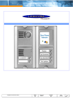
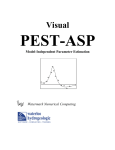
The set of valid key
codes and its relation to the standard OLS key-board are
depicted in Figure 1. The Interface makes no validity
check of the incoming data, but OLS will detect and dis
card invalid key codes.
Normally, the first keys sent over the Input Connection
(i.e. the first keys that the Network user. pushes) should
be those .n e c e s s a r y to log in to OLS.
The user may log in
and out many times during the l{fe of the Network connection,
and these operations are transparent to the Interface.
The
last keys sent over the Input Connection should log the
user off of OLS (SYST DOWN).
Failing to log off before
terminating the Networ~nnection allows the possibility
of a later Network user's finding himself already logged in.
The first byte of data received over the Input
.
Connection is discarded unexamined by the Interface,' which
assumes it to be zeros indicating message type zero in
compliance with Host-Host protocol.
No significance is
attached to Imp-message boundaries.
The second byte of
data received is not passed to OLS but is examined by the
Interface.
By appropriately selecting that second byte,
the user can cause to be suppressed by the Interface, any
or all of the three classes of output generated by OLS and
potentially relayable to the user over the Output Connection.
The byte is interpreted as follows:
Bit
Bit
Bit
Bits
0
1
2
=
=
=
3-7:
1:
1:
1:
suppress all
suppress all
suppress ~ll
not examiryed,
alphameric output.
curvilinear output.
special character output.
should be zeros.
Once made, this declaration prevails for the life of the
Network connections.
A user can avoid transmission of
output classes he is unable to process and would therefore
have to discard anyway, thus avoiding needless Network traffic.
A user operating from a teletype and capable of displaying
only alphameric ou~put, for example, might specify x'60'
and thereby suppr~ss all else.
(
:' ::'::-=:" :'=: ",
rr
":. ":'~ "__ r:-,",":"J...'
I
7~
! 12. 30
,
7.1
_)
.. ~ ~ ~... ~ "' ... ~ ' : ..... ~ '. -.....r : ~ ~ ....,
IlIT7
1!
II
,jll
";!'?
? -;J
J~ )
,,;}'- •
,
.:1,',
I
..;
Jl
,;,r::
.;,,;...'
I
:lI -..) u W
\
:
,--:':, 7 .
";!1.
R
E Fl L
"
.7.
-, c;
-.or
Ie
l" W L~
.y
.•,
./
-
5 3A
YST
I
!lSER
l ...-'- , r-, ITYfE
- 'ro
LXS1_'OJ',
t- ,
."
.. .. ..
....... ' -
J
•
- ' ~..J
'-"
~11' .~. I'llb;'~J 01"~. S~J~' S~'"; ~lc~"~~·F ~;ql~;~; 5'=~~~f;~:'s:~~F;i~';~l"
. "'1 . \
Sr\ \
..
"'1'~I S Ie
IN
1}\
r
Db
OL} !
1:l
L: -
0-;12
03
OF\
02
07 1
1F" ,
OD
:.:.:..... ='.':;:"~~ ..:. •._-_:.::::==
:, c .av-.. .=
\
i'
ez ~
· ) O f';1 ~:E"\
. c/Sl
A~
p rl:r
"'~i'
Q D?>: W E.G:, .~
25
---
5
...C . ::.r:\;; '-"' 11 : ~
BE
~
BS
.::..
.' ~ .:-_-:.::::t-=
~==-::...":.~ .=~-:.=;
75 7
B
;': ''''; - '~ ~.~. ':"':'':::-..'t~_
STO Rt: ;
52
~
eg
0
ENI S R
2C
I:
M.",,,, , c.r or 'i:
tJ
r
.
A E
__ "
Gr~R ESE1 B~ ~
.
~;r.,.;cl .:~.:".;;r.:Gd"~-:£~.:?::.'":.l
~ ..:-~ . ' . ... . ' ~ ~~ - ~~-: 1~~ '::.".· _· ;" ' · ~": -=;-:';'::= :-=1
Bo l!
5A -
6f) I@
1$
EP31 1_0 ~J : RH O
TrW IpS'1- . U f'SILON ,I IOTA . OM \CR~~Jli p!:
' A'1~ _. A31
ACO
A4
2ri
1(,
Cf7 gtt- /fA ,
~5 1
Lo~~
ZD!
, "-::' '''::''''-~''~-:'''-= ::-;' I "-""'.:"= ' ~·"R. _.._ _.. ,_.,
1;-
.
•
B3 1LJ Bl/
r
2? c 2 " - ';'~-; :" - ;;;", , .:.'==--,:;:;,:;:::::.= :.:. ~-:: . :-. '.:-::: -. : : :"".. -. -_';'''''':: Z-:?~'';';;.",''''==.:.:' -:.' :': ':- ~ .-~: -,"",=>..~~.:r..c:::='' ' ' "' '.;.J
-':;'·':=':"'
-:::":-=- ;::;'·= ~ ::: ":"-a· ~·~1 ' !·!..:.:--;..o;;, ::. ~ :; ~':':'7 :::-~ : :":'- :-•• ~-,:"
11 (HIZ
1B ~
\ DC
OB
Ej"'F(~--I;'~'JR ·r ~~~~~Dc" ·- A~--bE.-- '~~-L c~'~if:~,~f; '~'~
:- r..,
~
!
e. ~o!'. ~ T. .. &S_ -t., ·v.t .·..""':;.':.. ·_':.: ~ :-•.:;~- ~......' ~-:.. .: .;,..~..::.~ : ., ~::.:.:::-""':':==-...,.~ I. r, ~ ~ :;:::tI~-:~ I' ..U:..,' ;:. t ·=-..';..~"'t 1"":.>' ')-...::;. .~~-:. . ..r ,.:·: ,, ~._ . , » ~':' ~~ .: ..Jf:.: ~ "; :. '>" ... ~,~
.- •. ~~
.
.
7C If 7s 1
I:
5B : Of
*
.
sc lp"
so
I
AS
"l
0
p~ r._.~~l!'T...§-~- u..~~~ ..t.. _ s:~9 _.~_~_ ~'P : ,.~, ~j § 50 ; 5C ! -= ,.-:-:.~iJ~ _ 7 7 ~_
.t.LPg '~ IIS\ f,A~ D £L~~ lpJ. Bb !G ~" r'7 iT"";'fIl s I69 ~ I Kil P~~ ILI\"~~ i: 7A ( 73 ~~h 711'J. 72
F\
(.1.
(5
E2
(5
j
R
.
D c. y, IFcC:,
~ S-~':In "r- Ti' Z-:z. EA~ !X-r. A7
(!-!l Z3
r.,
r:
'7 I
~\
r
~:1'
"' . 1k'
~ .., !! ~ ~.J: ~
c' .-
-Nu AS B.E~~ E T~5 MLl1Lf I.-<--~~ - -> ~ .(
/I
(
•I
_
I') :'" ~ ~
7f -.,
ET
SF;"'.Ij SACKl ER~l SE
L_ _ =~1~=-~-~~-~?- is,,,~3~ L~~,~_~~;i; ~;~~~::c~~ ~. > '_~~_i " ,z~,3,L~_~ ~,L ~ ~ cA5~: 1
y'
_~~ "" · ·'~,-,"", . ; :; .o =.,. ...... ~..J<"::'~='·"'_""'=="""'-=!: ' ''''' "," ::c.." , ~ . ,r_ .....-._ "",""", ... : _~ ",,~.eoj
.J
R£nJ'
C.
.
:Lf: .~
~~/.
i
U~~ : -':': ," : :-,'~ =::7.; .:-;o ""~~:-:-;-:;-~~i:." ·' "
Figure 1. _ INPUT KEY CODE SET
--- - -.__.-_ . -_.._ - --- -
-
._
-
-- --------~...---
'-....-'
THE OUTPUT CONNECTION
With the exception of the first byte, data transmitted
over the Output Connection by the Interface consists of a
continuous string of variable-length records.
The first
byte sent consists of zeros, indicating message type zero,
to comply with Host-Host protocol, and should be discarded
by the user.
At present there are three classes of records
defined, one corresponding to each class of OLS output-
alphameric, curvilinear, and special characters.
Only
records of those classes which have been enabled by the
user will be transmitted; all other output will be suppressed
locally by the Interface.
Each record consists of a one
byte field specifying the output class, a one-byte output
class-dependent field, a variable-length data field, and a
two-byte field containing the combined length in bits
(unsigned) of the data and output-class-dependent fields.
Each record has the following form:
I
2
1
L+8
CLASS
DE?
FIELD
OUT
PUT
CLASS
'b ts
s------
L
i,
D ATA
--
s------
The integer above each field is the length of that field
in bytes (except where stated to the contrary).
The length
of a record, then, is given in bits by the contents of the
length field plus twenty-four.
The significance of the
data and class-dependent fields, and the output class
assignments are given in the following sections for each
output class.
A.
ALPHAMERIC OUTPUT (CLASS 1)
For alphameric output, the output class field contains
the following:
Bits 0-3:
Bits ·4 - 7 :
unpredictable
0001
The contents of the class-dependent field are unpredictable.
The data field contains the a l p h a mer i c display in the form
of a contiguous string of one-byte characters.
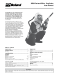
Any char
acter listed in Fi gur e 2 may be present.
The list includes
the Greek and Latin alphabets, a variety of special symbols,
as well as carri age control characters such as carriage
return, line feed, backspace, and erase.
Alphameric output r ecords emb o d y system-generated
messag es, LIST mode displays, lower key-board activity on
the TYPE level, TYPE level operators such as UP and DOWN.
etc.
The appearance of the character pair 'BACK ERA SE '
(x'S9BC') in a record represents a command to erase the
display scope.
When not immediately follow ed by ERASE.
BACK indicates a backspace operation.
'BREAK' (x '79' )
is used to facilitat e formattin g of long messages that may
be either printer- or display-scope-destined.
In g e n e r a t i n g
scope display, where there are twenty-five characters per
line, 'BREAK' should be interpreted as a carriage return;
in generating printer output, where longer lines are possible,
it should be interpreted as a space or blank ..
FIGURE 2.
NAME
A
B
C
D
E
F
G
H
I
J
K
L
M
N
0
P
Q
R
S
T
U
V
W
X
Y
Z
0
1
2
3
4
S
6
7
8
9
ALPHAMERIC OUTPUT CHARACTER SET
Lo w e r
Case
CODE
NAME
Cl
C2
C3
C4
C5
C6
C7
C8
C9
Dl
D2
D3
D4
D5
D6
D7
D8
D9
E2
E3
E4
E5
ALPHA
BETA
CHI
DELTA
EPSILON
PI
GAMMA
THETA
IOTA
SIGMA
KAPPA
LAMBDA
MU
ETA
Ot-HCRON
PI
PHI
RHO
SIGMA
TAU
UPSILON
NU
OMEGA
XI
PSI
ZETA
E6
E7
E8
E9
FO
Fl
F2
F3
F4
F5
F6
F7 .
F8
F9
ss 0
S5
S5
S5
1
2
3
ss 4
55 5
55 6
5S
5S
5S
Upper
Ca.se
CODE
81
82
83
84
85
86
87
88
89
91
92
93
94
95
96
97
98
99
A2
A3
A4
AS
A6
A7
A8
A9
BO
B1
B2
B3
B4
8
B5
B6
B7
B8
9
B9
7
(cont'd)
">-
NAME
CODE
-
NAME
CODE
-
PLUS +
MINUS SLASH I
APOSTROPHE I
LOGICAL AND &
ASTERISK *
EQUALS =
SEMI-COLON
LEFT PAREN (
RIGHT PAREN )
COMMA •
PERIOD
QUEST I ON rvlARK ?
LOGICAL OR
4E
60
61
70
50
5C
7E
SE
40
UNDERSCORE
AT SIGN @
POUND SIGN #
CENT SIGN ¢
DOLLAR S IGN -$
PERCENT SIGN %
COLON
LEFT BRACKET [
RIGHT BRACKET ]
LESS THAN <GREATER THAN >
QUOTE II
LOGICAL NOT
EXCLAMATION
60
7C
SO
6B
4B
6F
4F
C~rriage
Control
BACK (backspace)
59
RETURN (carriage
49
return)
TAB (advance to
77
next tab)
UP (line feed up)
06
ENL (line feed up)
27
DOWN (line feed
07
down)
CON (line feed
28
down)
RS (position to
13
upper left of
display area)
ERASE
· BC
BREAK (for displ ay
79
scope: RETURN
for line
printer: SPACE)
SPACE (blank)
40
78
4A
58
6C
7A
73
74
4C
6E
7F
SF
~
SA
Special List
Mode Characters
SPACE
POST LIST
DIVIDE 0
MULTIP LY (i)
SUBTRACT G
ADD ffi
CARRIAGE RETURN
DELETE f2a
POINTER
62
63
64
65
66
I
67
68
69
6A
Miscellaneous
DOT (curvilinear
display,
dot-dot mode)
78
NOTE: .
''>-'-
Codes are specified in hexadecimal and are eight bits.
ISS'
means 'superscript'
B.
CURVILINEAR OUTPUT (CLASS 2)
For curvilinear output, the output class field
contains th~ following:
Bits 0-1:
00 indicates line segment mode
(adjacent display points are to
be connected by straight lines)
01 indicates dot mode
10 indicates character mode (the
class-dependent field contains a
character from Figure 2 which is
to be displayed at each point
('dot-dot' mode is character mode
with the display character 'DOT'
Bits 2-3:
Bits 4-7:
unpredictable
0010
(x'78')) .
For character mode, the class-dependent field contains the
display character ; in other cases, the contents of that
field are unpredictable.
The data field contains a list
of X-Ydisplay coordinates as depicted below:
2
2
X. and Y. are thet~ and Y display coordinates--after
staling -~of the i
componen t of the vector represented by
this record.
Each coordinate is contained in a two -byte
field, therefore one compon ent in four bytes, and hence
the context of the vector bein g displayed is given by the
contents of the length field minus ei ght divided by thirty-two.
The assumed display are a is square, with origin at lower
left, and both X and Y ranging between 0 and 4095.
There
is a one- t 0 - on e correspond enc e b etwe en ve ct or s -d i s played
and curvilinear output records transmitted.
"......,-
,
C.
SPECIAL CHARACTER OUTPUT (CLASS 3)
For special character output, the output class field
contains the following:
Bits 0-3:
Bits 4-7:
unpredictable
0011
The contents of the class-dependent field are unpredictable.
The data field contains a contiguous string of variable
length characters, each representing either a move in one
of sixceen directions or a change in position relative to
the lower right corner of the last character frame (where
for alphameric and special character display, the display
area is square, 4096 units in extent vertically and horizon
tally, and a character frame is 160 units wide and 224 units
high).
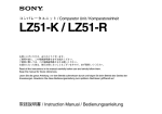
The sixteen characters which define move operations
are listed in Figure 3, and each is one byte long.
Such a
character indicates a move from the current position, in
the specified direction, a distance equal to that
of a move in the same direction from the center of a
64-unit square to its perimeter.
The length of the move
is therefore functionally related to its direction.
A change in position relative to the lower right
corner of the last character frame is represented by a
four-byte character of the form:
"
I
x'70'
12 bits
.6 X
12 bits
boy
where 6 X and A Yare signed quantities indicating the
number of units change along each coordinate.
FIGURE 3.
DIRECTION
""--
000.0
022.5
045.0
067.5
090.0
112.5
135.0
157.5
180.0
202.5
225.0
247.5
270.0
292.5
315.0
337.5
SPECIAL CHARACTER VECTOR CHARACTER SET
CODE
--
47
48
Sl
52
53
54
55
56
57
58
41
42
43
44
45
46
NOTE:
Codes are specified in hexadecimal and are eight bits.
Directions are specified in degrees, increasing counter
clockwise from 0° at positive X in an X-Y coordinate system.