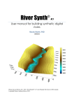
1
Stream Geomorphic Assessment Tools
Appendix H
Development of Stream Corridor Buffers
Development of Stream Corridor Buffers in Step 09
Introduction
Stream corridors are created in Step 09 by creating buffers around certain features and then
combining those buffers in a specific manner. The concepts of buffers and features are used
from the perspective of Geographic Information Systems.
Features can be points, lines (or polylines, which are a connected string of line segments) or
polygons (enclosed or bounded areas). A feature is a digital “model” or representation of an
object in the real-world. As examples: Points can represent such objects as fire hydrants, signs,
reach points; polylines can represent such things as road centerlines, electric transmission lines,
stream centerlines; and polygons can represent such things as town boundaries, rivers, lakes,
valleys.
Within the Stream Geomorphic Assessment Tools (the Tools), the predominant feature type is a
polyline. Stream centerlines, meander centerlines and the valley walls are represented as
polylines.
Note: While valley walls are digitized and provided as polygons, the toes of the valley
walls are “extracted” from those polygons and used as polylines.
With the release of Version 3 of the Tools, significant flexibility has been incorporated into the
development of stream corridors via processing Step 09. This flexibility is based upon the
implementation of the following concepts:
Application – Through an application, one establishes a linkage to a buffer reference
table. In effect, an application can be associated with one and only one buffer
reference table. A buffer reference table, however, can be associated with any
number of applications.
Buffer Reference Table – A buffer reference table contains records that define the
parameters to be used in creating buffers around specific features. (Features
refer to the stream centerline, meander centerline and valley walls.) There are
two versions of the buffer reference table that identify the source of data to be
used in defining the buffer for a reach. The sources are:
o
o
Stream Geomorphic Assessment Phase I; or
Stream Geomorphic Assessment Phase II.
Buffer Parameters – Each record in a buffer reference table defines parameters to be
used in buffering features. These parameters establish the requirements for
buffering as follows:
(1) Whether a specific feature will be buffered,
(2) The width of the buffer to be used for a specific feature,
(3) Whether a default buffer of a specified with around the stream centerline is to
be used,
(4) Whether an alternate buffer (using the stream centerline) is to be developed
when a meander centerline is not present, and
(5) Whether to ignore buffering the meander centerline if valley walls are not
present.
Accessing a specific record in a Buffer Reference Table – A buffer reference table
can be composed of any number of records. Each record is identified by a key;
and the key is a reflection of certain conditions that categorize a reach. For
example, a key may reflect a specific stream type, stream group designation (e.g.
sensitivity class), valley confinement group and valley slope group.
SGAT – Version 3
VT Agency of Natural Resources
- H-1 -
Revision: December 10, 2003
Development of Stream Corridor Buffers in Step 09
Each record contains the parameters to be used in creating a stream corridor for
reaches whose conditions are reflected in the key.
A specific hierarchy is implemented to combine the conditions of a reach in an
attempt to find a record with a matching key in the buffer reference table. This
hierarchy is in the order of the most specific (or highest sensitivity) conditions to
the most general. The most general conditions are reflected in a record
containing a key value of “Default”, which reflects the general parameters for
creating a stream corridor for the application associated with the buffer reference
table.
Note: All buffer reference tables must have a record containing a key with a
value of “Default”. The buffering parameters in this record will be used in the
absence of finding any other record that meets the conditions of the reach.
Import of Phase I/Phase II Data – The data necessary to define the conditions of a
reach are not inherent in the calculations or derivation of data within the Tools.
This data is, however, entered by the user in a Microsoft Access data base as
part of the assessment process. As a result, the necessary data must be
transferred from the data base into the attribute table for the reach point theme.
Each feature, if present, is buffered in accordance with the applicable parameters in the record
selected from the buffer reference table. These “component” buffers are then merged using
specific rules to form the stream corridor. This permits creating a stream corridor specific to the
conditions of a given reach.
The implementation of the above has been accomplished in such a manner that it is, for the most
part, transparent to the user. Further, the average user will not need to understand the details
presented in this Appendix. However, for users who have specific needs or applications, the
information presented herein can be used to tailor the buffering procedure in arriving at specific
stream corridor configurations.
This Appendix will provide detailed descriptions of the concepts introduced above. However,
some background on relevant aspects of the Geomorphic Assessment is necessary. These are
presented in the next section.
SGAT – Version 3
VT Agency of Natural Resources
- H-2 -
Revision: December 10, 2003
Development of Stream Corridor Buffers in Step 09
Related Background on the Geomorphic Assessment Process
During the Phase I assessment process, the following data is captured for each reach:
•
•
•
•
Stream type,
Sensitivity Class (grouping of stream types),
Valley slope and
Valley confinement.
During the Phase II assessment process, the following data may be captured for each reach:
•
•
•
•
Stream type (revision from or more detailed stream typing than conducted in Phase I),
Sensitivity Class (revision from Phase I grouping of stream types),
Whether the existing stream type represents a departure from the reference stream type,
Whether a major channel adjustment is in progress,
The above data is entered into and maintained in the Phase I/II Access Data Base on a reach
basis for the watershed being assessed. A brief description of the data elements follows.
Stream Type
The stream type is a concatenation of up to three characters that generally defines the reach, as
described below:
Example: C2b, where
“C” (first character) defines the class associated with the reach. The class indicates
certain characteristics of the reach such as entrenchment, width, slope, etc.
“2” (second character) defines the dominant sediment material. This character may not
always be present as part of the stream type identifier (especially during Phase I
assessment).
“b” (third character) is a slope modifier and categorizes the slope of the channel, when
the slope is different than that associated with the class. This modifier may not
always be present as part of the stream type identifier.
Stream Group (Sensitivity Class)
As illustrated in the following table, the sensitivity class is used to “group” stream types based
upon similar characteristics.
Stream Group
Sensitivity Class
VL
Very Low to Low
LW
Low to Moderate
MD
Moderate to High
HI
High to Very High
VH
Very High to Extreme
EX
Extreme
The column under Stream Group represents the values for the field StrmGroup as used in
defining a stream corridor via a buffer reference table. These values may be used in matching
data entered by a user during a geomorphic assessment to a key in a buffer reference table. As
a result, the values must be consistent between those used during the assessment and the
development of the buffer reference tables.
SGAT – Version 3
VT Agency of Natural Resources
- H-3 -
Revision: December 10, 2003
Development of Stream Corridor Buffers in Step 09
Departure from Reference Stream Type
“Whether the existing stream type is a departure from reference stream type” is, at present, a
Yes/No data element.
Major Channel Adjustment
“Whether a major channel adjustment is in progress” is, at present, a Yes/No data element.
Valley Slope
The following table for Valley Slope categorizes streams using a range of valley slopes.
Group
a
b
c
c
Valley Slope
Designation
Very Steep
Moderate to Steep
Moderate to Low
Gentle
Slope Range
> 4%
>= 2% but <= 4%
> 0.5% but <= 2%
<= 0.5%
The column under Group represents the values used for the field VSGroup as used in defining a
stream corridor via the buffer reference table.
Valley Confinement
The following table for Valley Confinement categorizes streams using a range of confinement
ratios (valley width divided by channel width).
Group
1
1
2
3
Code
NC
SC
NW
BD
3
VB
Valley Confinement
Designation
Valley Width / Channel Width Ratio
Narrowly Confined
>= 1 and < 2
Semi Confined
>= 2 and < 4
Narrow
>= 4 and < 6
Broad
>= 6 and < 10
>= 10 with abandoned terraces on
Very Broad
one or both sides
The column under Group represents the values used for the field VCGroup as used in defining a
stream corridor via the buffer reference table.
When using the Stream Geomorphic Assessment Tools (Tools) for floodway determination and
for Phase I of stream geomorphic assessment, the data elements described above serve as the
foundation for determining the stream corridor for each reach (Step 09 in Tools).
The tables and information provided in this section were current as of the date of writing this
manual. For current and additional information on the data elements, refer to the Stream
Geomorphic Assessment Handbooks available from:
River Corridor Management Section, Water Quality Division,
Department of Environmental Conservation, Agency of Natural Resources
103 South Main Street, Building 10 North
Waterbury, VT 05671-0408
SGAT – Version 3
VT Agency of Natural Resources
- H-4 -
Revision: December 10, 2003
Development of Stream Corridor Buffers in Step 09
Concept of Application in the Tools Extension
The concept of applications has been implemented in the Tools to permit certain functionality to
be used for different purposes. The following table lists the applications that have currently been
defined:
Application
Floodway Determination Option 1
Floodway Determination Option 2
Stream Geomorphic Assessment
Application
(Applicatn)
FD Option 1
FD Option 2
SGA
Buffer Reference Table
(BuffrTable)
SysBufOpt1.dbf
SysBufOpt2.dbf
SysBufSGA.dbf
Access Level
(AccessLvl)
2
2
1
Note: Floodway Determination (Options 1 and 2) are defined in the “Floodway
Determination Technical Guidance” document and Stream Geomorphic Assessment is
defined in the “Stream Geomorphic Assessment Handbooks”. These documents are
available from the River Corridor Management Section (refer to address on previous
page).
The only difference between the applications, as far as use of the Tools is concerned, is in the
development of stream corridors (Step 09). This difference is implemented through the use of
buffer reference tables.
The above table actually represents the contents of the system table “SysApps.dbf”. The field
names in the system table are shown within parentheses in the column heading. As illustrated in
the table, each application (row) is associated with a buffer reference table. Once an application
is selected, the buffer reference table to be used in Step 09 has been identified.
To establish the application to be used, one first identifies the user type and then the application
on the Setup Dialog. The upper area of that dialog is shown below:
The user type must be established first because certain applications are restricted to certain user
types. Whenever the user type or application are changed on the Setup Dialog, the selected
values are entered into the system table named ”SysSystem.dbf”. That table maintains the
currently selected values. Thus, when you exit the Tools extension and, subsequently, re-enter
the extension, the user type and application last selected will remain known.
In certain circumstances, the user type and application may be pre-defined and “locked”. In these
cases, one will not be allowed to alter either setting. This, in turn, pre-determines the buffer
reference table that will be used for determining stream corridors (via Step 09). This is done so
that those who will only be using one specific application, such as stream geomorphic
assessment, will not have to be confronted with “decisions” that are not relevant to their work.
The records of the “SysApps.dbf” table must be manually edited to effect any changes. It is
imperative that the buffer reference table referred to in a record actually exist in the SysData
SGAT – Version 3
VT Agency of Natural Resources
- H-5 -
Revision: December 10, 2003
Development of Stream Corridor Buffers in Step 09
directory. If the buffer reference table does not exist, an error message will be issued during the
initialization procedure of the Tools extension and access to the functions will be prevented.
Note: Additional verification of each buffer reference table is performed during this
procedure. If any errors are detected, appropriate error messages will be issued.
Access to any functions will be prevented until such error conditions are cleared up.
Refer to the Section of the User Manual for the Tools entitled “Initialization Procedure” for
a description of the error conditions.
As implied, one can edit the “SysApps.dbf” table to include additional “applications”. If this is to
be done, adhere to the following rules:
(1) Any editing should not be performed while the Tools extension is active. Always exit the
extension (click on Exit on the Setup Dialog) before editing.
(2) Do not modify any data for the existing records in the SysApps.dbf table. These
“applications” are to be used for their intended purposes and have statutory or scientific
basis.
(3) Enter the name to be associated with the application into the Applicatn field.
(4) Enter the name of a valid buffer reference table (which will exist in the SysData directory)
into the BuffrTable field. The format, contents and use of buffer reference tables are
described subsequently in this Appendix.
(5) If the new application pertains to stream geomorphic assessment and is to be available to
watershed groups, enter a value of one (“1”) in the AccessLvl field. Otherwise, enter a
value of two (“2”).
Once the editing has been completed and the referenced buffer reference table is copied or
moved to the SysData directory, the Tools extension will list the application on the Setup Dialog.
While in that dialog, select the application. After that, the associated buffer reference table will be
used during processing of Step 09.
Buffer Reference Tables
As described in the preceding section, a buffer reference table is associated with each
application. A buffer reference table contains records that define the parameters to be used in
creating buffers around specific features. (Features refer to the stream centerline, meander
centerline and valley walls.) During the development of stream corridors in Step 09, specific
records in these tables will be retrieved based upon assessment data for a given reach.
There are two formats that may be used in defining a buffer reference table. The format should
be selected based upon the source of data to be used in defining the stream corridor for a reach.
The sources are:
o
o
Stream Geomorphic Assessment Phase I; or
Stream Geomorphic Assessment Phase II.
The differences in the two formats are the presence of the fields:
o
o
VCGroup and VSGroup (for use with Phase I data) OR
Adjustment and Departure (for use with Phase II data).
Only one of the above sets of fields may exist in a buffer reference table. All other fields are
identical in format and content. The two formats for buffer reference tables are provided on the
following pages.
SGAT – Version 3
VT Agency of Natural Resources
- H-6 -
Revision: December 10, 2003
Development of Stream Corridor Buffers in Step 09
Format of Buffer Reference Tables for
Stream Geomorphic Assessment (Phase I) and Floodway Determination Option 1
Field Name Format
Description
Format of Key field used for Stream Geomorphic Assessment and Floodway
Determination Option 1: Various concatenations which may include values from
StrmGroup, StrmType, VCGroup, and VSGroup. Refer to descriptions of these
Key
C (24)
fields below and the discussion in the text regarding how a specific value is to be
created and how a record will be retrieved. A value of “Default“ designates a
default record, which will be used if no other key is matched.
Group designation for stream type, e.g. sensitivity class. For permissible values,
StrmGroup
C (16)
refer to the column Stream Group and its definition in the table presented earlier.
Stream Type designation: First and second characters identifying Stream Class
(must always be present) and Dominant Sediment Material (if not present, a
StrmType12 C (2)
dash, “-“, must be used).
Stream Type designation: Third, and optional, character identifying Slope Modifier
StrmType3
C (1)
(if not present, a dash, “-“, must be used)..
Valley Confinement Group designation. For permissible values, refer to the column
VCGroup
C (3)
Group and its definition in the table for Valley Confinement presented earlier.
Valley Slope Group designation. For permissible values, refer to the column
VSGroup
C (3)
Group and its definition in the table for Valley Slope presented earlier.
Fixed distance for creating a default buffer around the stream centerline. Value of
DefaultBuf
N (6, 0) this field represents a fixed distance on either side of the stream with a total width
of twice the value. A value of zero will indicate this buffer is not to be used.
Channel width multiplier for defining a buffer around the stream centerline. Buffer
distance will be the value of this field multiplied by the channel width and will
StreamCL
N (6,3)
represent distance on either side of the stream with a total width of twice the
product. A value of zero will indicate this buffer is not to be used.
Channel width multiplier for defining a secondary buffer based upon the stream
SCLnoMCL N (6,3)
centerline when a meander centerline is not present. A value of zero will indicate
this buffer is not to be used.
Channel width multiplier for defining a buffer around the meander centerline. Buffer
distance will be the value of this field multiplied by the channel width and will
represent distance on either side of the meander centerline with a total width of
MeanderCL N (6,3)
twice the product. A value of zero will indicate this buffer is not to be used. If no
meander centerline feature is present for a given reach, no meander centerline
buffer will be created. (See also RequireVW below).
Channel width multiplier for defining a buffer from the valley toe in the direction
toward the stream centerline. Buffer distance will be the value of this field
multiplied by the channel width and will represent distance on the side of the valley
ValleyToe
N (6,3)
toe towards the stream centerline. Buffers will be created using the left and right
valley walls. A value of zero will indicate this buffer is not to be used. If no valley
toe feature is present for a given reach, no valley toe buffer will be created.
Permissible values are “Y” (Yes) or “N” (No) defining whether the valley toe feature
must be present for a given reach to perform buffering of the meander centerline
(see MeanderCL above). If the value is “Y” (Yes), buffering of the meander
RequireVW C (1)
centerline will only be performed if the valley toe feature is present. If the value is
“N” (No) then buffering of the meander centerline will be performed independent of
whether a valley toe feature is present.
Note: The values in fields StrmType12, StrmType3, VCGroup and VSGroup are not used within
the Tools. These fields, however, must be present in the buffer reference table. The Tools uses
the existence of fields VCGroup and VSGroup to specify the use of the buffering decision tree for
Phase I data (i.e. for Assessment and Floodway Determination Option 1). Using Phase I data for
a given reach, the decision tree identifies which record to use for obtaining the buffering
parameters. In addition, these fields provide documentation for the value of the Key field. If any
of these fields are not used in forming the value of the Key field, the value of the field should be
left blank; otherwise, adhere to the format described in the table above.
SGAT – Version 3
VT Agency of Natural Resources
- H-7 -
Revision: December 10, 2003
Development of Stream Corridor Buffers in Step 09
Field Name
Key
StrmGroup
StrmType12
StrmType3
Departure
Adjustment
DefaultBuf
StreamCL
SCLnoMCL
MeanderCL
ValleyToe
RequireVW
Format of Buffer Reference Table for Floodway Determination Option 2
Format
Description
Format of Key field used for Floodway Determination Option 2: Various
concatenations which may include values from StrmGroup, StrmType, Departure
and Adjustment. Refer to descriptions of these fields below and the discussion in
C (24)
the text regarding how a specific value is to be created and how a record will be
retrieved. A value of “Default“ designates a default record, which will be used if no
other key is matched.
Group designation for stream type, e.g. sensitivity class. For permissible values,
C (16)
refer to the column Stream Group and its definition in the table presented earlier.
Stream Type designation: First and second characters identifying Stream Class
(must always be present) and Dominant Sediment Material (if not present, a
C (2)
dash, “-“, must be used).
Stream Type designation: Third, and optional, character identifying Slope Modifier
C (1)
(if not present, a dash, “-“, must be used).
Designation of existing stream departure from reference stream, which at present is
C (1)
either “Y” (for “Yes”) or “N” (for “No”). If value does not exist, use a dash (“-“).
Designation of whether existing stream is in major adjustment, which at present is
C (1)
either “Y” (for “Yes”) or “N” (for “No”). If value does not exist, use a dash (“-“).
Fixed distance for creating a default buffer around the stream centerline. Value of
N (6, 0) this field represents a fixed distance on either side of the stream with a total width
of twice the value. A value of zero will indicate this buffer is not to be used.
Channel width multiplier for defining a buffer around the stream centerline. Buffer
distance will be the value of this field multiplied by the channel width and will
N (6,3)
represent distance on either side of the stream with a total width of twice the
product. A value of zero will indicate this buffer is not to be used.
Channel width multiplier for defining a secondary buffer based upon the stream
N (6,3)
centerline when a meander centerline is not present. A value of zero will indicate
this buffer is not to be used.
Channel width multiplier for defining a buffer around the meander centerline. Buffer
distance will be the value of this field multiplied by the channel width and will
represent distance on either side of the meander centerline with a total width of
N (6,3)
twice the product. A value of zero will indicate this buffer is not to be used. If no
meander centerline feature is present for a given reach, no meander centerline
buffer will be created. (See also RequireVW below).
Channel width multiplier for defining a buffer from the valley toe in the direction
toward the stream centerline. Buffer distance will be the value of this field
multiplied by the channel width and will represent distance on the side of the valley
N (6,3)
toe towards the stream centerline. Buffers will be created using the left and right
valley walls. A value of zero will indicate this buffer is not to be used. If no valley
toe feature is present for a given reach, no valley toe buffer will be created.
Permissible values are “Y” (Yes) or “N” (No) defining whether the valley toe feature
must be present for a given reach to perform buffering of the meander centerline. If
the value is “Y” (Yes), buffering of the meander centerline will only be performed if
C (1)
the valley toe feature is present (see MeanderCL above). If the value is “N” (No)
then buffering of the meander centerline will be performed independent of whether
a valley toe feature is present.
Note: The values in fields StrmType12, StrmType3, Departure and Adjustment are not used
within the Tools. These fields, however, must be present in the buffer reference table. The Tools
uses the existence of the fields Departure and Adjustment to specify use of the buffering decision
tree for Phase II data (i.e. for Floodway Determination Option 2). Using Phase II data associated
with a given reach, the decision tree identifies which record to use for obtaining the buffering
parameters. In addition, these fields provide documentation for the value of the Key field. If any
of these fields are not used in forming the value of the Key field, the value of the field should be
left blank; otherwise, adhere to the format described in the table above.
SGAT – Version 3
VT Agency of Natural Resources
- H-8 -
Revision: December 10, 2003
Development of Stream Corridor Buffers in Step 09
In the buffer reference tables, the field StrmGroup can be used in a much broader sense than
sensitivity class. It can be used to relate stream types in any manner. It is important, however,
that whatever values are assigned to StrmGroup be consistent between field data collection and
development of the buffer reference tables described herein.
Each buffer reference table must have a record with a Key value of Default. This record will
contain the general buffering parameters to be used if no other record can be found to match the
“conditions” of a reach.
There are three buffer reference tables distributed with the Tools:
SysBufSGA.dbf – for use with the stream geomorphic assessment Phase I (based upon
Phase I data);
SysBufOpt1.dbf – for use with the Floodway Determination Option 1 (based upon Phase I
data); and
SysBugOpt2.dbf – for use with Floodway Determination Option 2 (based upon Phase II
data).
At the time of writing this Appendix, the content of the buffer reference tables is shown in the
following:
Key
StrmGroup
StrmType12
Buffer Reference Table for the Phase 1 Stream Geomorphic Assessment
StrmType3
VCGroup
VSGroup
DefaultBuf
StreamCL
SCLnoMCL
Default
Key
100
StrmGroup
StrmType12
2.5
0.5
StrmGroup
Low
Mod
ModYY
ModNY
High
Default
Low
Mod
Mod
Mod
High
StrmType12
ValleyToe
RequireVW
4
8
Y
ValleyToe
RequireVW
6
N
ValleyToe
RequireVW
4
6
6
6
6
N
N
N
N
N
N
Buffer Reference Table for Option 1 of the Floodway Determination Procedure
StrmType3
VCGroup
VSGroup
DefaultBuf
StreamCL
SCLnoMCL
MeanderCL
Default
Key
MeanderCL
3
3
Buffer Reference Table for Option 2 of the Floodway Determination Procedure
StrmType3
Departure
Adjustment
DefaultBuf
StreamCL
SCLnoMCL
MeanderCL
Y
N
Y
Y
0.5
0.5
0.5
0.5
0.5
0.5
2
3
3
3
3
2
3
3
3
3
To summarize:
•
Selecting an application on the Setup Dialog establishes the buffer reference table that
will be used in Step 09. (Refer to the table on page H-5.)
•
In the buffer reference table, the presence of the fields
o
o
VCGroup and VSGroup indicate that Phase I data and decision tree will be used.
Adjustment and Departure indicate that Phase II data and decision tree will be
used.
Let’s take a close look at a single record in a buffer reference table. Each record contains the
buffering parameters to be used in creating a stream corridor. The method for determining which
record to be used (or the decision tree) will be presented subsequently.
SGAT – Version 3
VT Agency of Natural Resources
- H-9 -
Revision: December 10, 2003
Development of Stream Corridor Buffers in Step 09
Buffering Parameters
Each record in a buffer reference table contains the following fields:
DefaultBuf (default buffering specifications used with the stream centerline),
StreamCL (stream centerline buffering specifications),
MeanderCL (meander centerline buffering specifications),
SCLnoMCL (buffering specifications used with the stream centerline when no meander
centerline is present),
ValleyToe (buffering specifications for toe of valley wall) and
RequireVW (specification that valley walls be present in order for any buffering to be
performed on the meander centerline).
The above define the buffering parameters that are to be applied for a given reach.
The field RequireVW is used to differentiate between policies used in calculating the stream
corridor for stream geomorphic assessment from those for floodway determination. For stream
geomorphic assessment, at present, a buffer for the meander centerline is not created if valley
walls are not present for the reach. As a result, all records in the buffer reference table for the
stream geomorphic assessment will contain the value of “Y” for this field. Values for this field will
be “N” for all other applications.
The Tools has been developed such that stream corridor definition is composed of merging
“component” buffers created using the following features:
Default Buffer (fixed distance from stream centerline)
Stream Centerline (multiple of channel widths)
Meander Centerline (multiple of channel widths)
Valley Wall (toe) (multiple of channel widths)
The Tools will develop each of the component buffers in accordance with the criteria in the buffer
reference table for the designated application. In addition, the following rules will apply:
1. Per the value for the field DefaultBuf, a default buffer will (or will not) be created. If
the value is zero, no default buffer will be created. Otherwise, a buffer equal to the
value, which represents a fixed distance, on either side of the stream centerline will
be created. The value of the DefaultBuf field is to be in feet.
2. If a given feature (stream centerline, meander centerline or valley wall) is not present
for a given reach, that (or those) component buffer(s) will not be created.
3. If the value in the buffer reference table for a component buffer is zero (0), that
component buffer will not be created.
4. Where a meander centerline is not present, a second buffer will be created on the
stream centerline where the channel width multiplier has been supplied in the field
“SCLnoMCL”. If, however, the value for the field SCLnoMCL is zero, no buffer will be
created.
5. If a given feature is present and a non-zero value is found in the buffer reference
table for a component buffer, a buffer will be created. The value in the buffer
reference table will be multiplied by the channel width for the reach to define the
buffer distance. (The buffer distance represents the distance from the feature to the
edge of the buffer, i.e. on either side.) Note: The default buffer is a fixed distance as
specified in (1) above.
SGAT – Version 3
VT Agency of Natural Resources
- H-10 -
Revision: December 10, 2003
Development of Stream Corridor Buffers in Step 09
6. Per the field RequireVW in the reference table, a buffer for the meander centerline
will (or will not) be created if valley walls are not present.
7. If a component buffer is created using the meander centerline and the valley walls
are present for that reach, component buffer will be constrained to fall within the toes
of the valley walls. (I.e. the meander centerline buffer will be clipped off by the valley
wall polygon, if present).
8. The final buffer will be the composite (sum) of the component buffers created as per
the corridor delineations described in the assessment protocols (Appendix E) or the
VTDEC Floodway Determination Technical Guidance.
9. Any “holes” formed within the composite buffer will be removed to provide complete
coverage.
A graphic example of the procedure used in developing the component buffers and the merging
of those to form the stream corridor is provided at the end of this Appendix.
Accessing a specific record in a Buffer Reference Table
The buffer reference tables and the logic (or decision tree) to access a specific record have been
designed to permit the use of buffering parameters for very specific conditions and or
configurations of a reach. These conditions and configurations are identified during the Phase I
and Phase II assessment efforts.
If Phase I data is being used, certain combinations of the following data elements can be used to
define buffering parameters:
•
•
•
•
•
Stream Type,
Stream Type slope modifier,
Valley Confinement Group,
Valley Slope Group and
Stream Group (e.g. sensitivity class).
If Phase II data is being used, certain combinations of the following data elements can be used to
define buffering parameters:
•
•
•
•
•
Stream Type,
Stream Type slope modifier,
Whether a major channel adjustment is in progress,
Whether the existing stream type is a departure from the reference stream type and
Stream Group (e.g. sensitivity class).
Note: Remember the application selected on the Setup Dialog identifies the buffer reference
table to be used. The presence of the fields VCGroup and VSGroup in the buffer reference
table establish the use of Phase I data. Or, the presence of the fields Adjustment and
Departure in the buffer reference table establish the use of Phase II data.
SGAT – Version 3
VT Agency of Natural Resources
- H-11 -
Revision: December 10, 2003
Development of Stream Corridor Buffers in Step 09
To create a buffer reference table that contained all possible combinations of the data elements
would involve creating literally hundreds (if not more) records. This would be cumbersome,
potentially error-prone and difficult to manage. Instead a hierarchical method has been
implemented for designing the buffer reference tables and for accessing specific records in those
tables. The method implemented recognizes that
•
Only a few reach conditions (represented by specific combinations of the data elements
listed above) require special consideration for buffering; and
•
Flexibility is required to add or alter specific buffering requirements for any combination of
the data elements as the needs dictate.
An example is used to illustrate the concepts implemented for Floodway Determination Option 2
(and therefore Phase II data). Assume that there are six unique stream types “Y1”, “Y2”, “Y3a”,
“Y3b” and “Z1”. (Keep in mind that experience may lead to the definition of new stream types.)
These stream types are associated with stream sensitivity classes as follows: “Y1” and “Z1” are
Low, “Y2” and “Y3a” are moderate and “Y3b” is high. Each stream type may be associated with a
departure from reference stream type and may be experiencing major adjustment. To provide the
capability where each unique combination of the data elements could be assigned unique
buffering criteria would require the definition of 72 records (6 stream types * 3 sensitivity classes *
2 departure conditions * 2 major adjustment conditions). Experience, however, indicates that only
a few records are required. The following table exemplifies a set of records.
Key
Strm
Group
Strm
Type12
Y3bYY
Y3
Y3
Y3
Mod
Strm
Type3
b
Depar
ture
Adjust
ment
Y
Y
Default
Buf
Stream
CL
SCL
noMCL
Meander
CL
Valley
Toe
Require
VW
Mod
Default
0
2.5
3
4
8
N
0
2.5
3
3
8
N
0
2.5
3
3
6
N
0
2.5
3
2
5
N
In the above example note that different buffering requirements (not intended to be realistic) are
identified in each record. The following describes each record:
Record 1 pertains to stream type “Y3b” (Y3 with slope modifier appended) when it is
undergoing Major Adjustment and is a departure from the reference stream.
Note: Sensitivity class (stream group) is disregarded.
Record 2 pertains to all other conditions of stream type “Y3” regardless of slope
modifiers, sensitivity class, departure condition or major adjustment condition.
Record 3 pertains to all other stream types in the sensitivity class “Mod” regardless of
stream type, departure condition or major adjustment condition.
Record 4 pertains to all remaining stream types regardless of sensitivity class, departure
condition or major adjustment condition.
In summary, creating a buffer reference table requires that one define records from the most
specific conditions (using meaningful combinations of the data elements) that require “special
attention”. After those, have been defined, records are defined on a more and more aggregate
level. Finally, a default record is required to cover all remaining conditions.
SGAT – Version 3
VT Agency of Natural Resources
- H-12 -
Revision: December 10, 2003
Development of Stream Corridor Buffers in Step 09
A Default record can be included for each combination of departure condition or major adjustment
condition. However, a Default record must also be included without reference to those
conditions. The following table illustrates this concept:
Key
Strm
Group
Strm
Type12
Strm
Type3
Depar
ture
Adjust
ment
Default
Buf
Stream
CL
SCL
noMCL
Meander
CL
Valley
Toe
Require
VW
DefaultYY
Y
Y
a
b
c
d
e
N
DefaultYN
Y
N
f
g
h
i
J
N
DefaultNY
N
Y
k
l
m
n
o
N
DefaultNN
N
N
p
q
r
s
t
N
u
v
w
x
y
N
Default
Note: Specific records for key values of “Default with conditions appended” can be
omitted if the buffering requirements are the same as the overall Default record (last
record in the above table).
Note: At a minimum each buffer reference table must have one record with a key value
of “Default” and only values for the following fields: DefaultBuf, StreamCL, MeanderCL,
ValleyToe and RequireVW. All other fields would be blank.
The first column in the previous tables refers to a “key”. The values for this field are simply
formed by various combinations (concatenation) of the values in StrmGroup, StrmType,
Departure and/or Adjustment. Access to a specific record will be by the value in the key field.
For each reach, the Tools will construct keys in a pre-determined order using data collected in
either the Phase I or Phase II assessments. After a key is constructed, an attempt is made to find
a matching key in the buffer reference table. If the key is found, the associated buffering
parameters are used to define the stream corridor for the reach. If, however, the key is not found,
the next key in the pre-determined order is constructed. This process is repeated until the
generic key of ”Default” is constructed; at which time the record from the buffer reference table
having the same value will be used to obtain the buffering parameters.
Note: It is mandatory that each buffer reference table contain a record with a key value
of “Default”. The presence of such a record in each table is verified during the
initialization procedure for the Tools extension. If no such record is found in any buffer
reference table, an error message is issued and access to the Tools extension is
prevented.
The preceding has the following implications:
1. The data collected from the Phase I and Phase II assessments is entered and maintained
in a Microsoft Access data base; and must be transferred into the attribute table for the
Reach Point theme. The approach for performing this task is described in a subsequent
section of this Appendix.
2. The pre-determined order in which keys are constructed must be carefully defined and
followed in both the development of buffer reference tables and the search for a matching
key in the Tools.
The pre-determined order in which keys are to be constructed is defined through the decision
trees shown on the following two pages. When designing or implementing changes to records
within a buffer reference table, review the decision tree with respect to the order in which
combinations of the data elements are used to form a Key. The order, from left to right,
represents the most “sensitive” and specific cases to the most general. Identify where a new
record should fit in the hierarchy. Then, take time to see if inserting that record will affect others;
and, if so, what changes or new records are required to make the hierarchy work.
SGAT – Version 3
VT Agency of Natural Resources
- H-13 -
Revision: December 10, 2003
Development of Stream Corridor Buffers in Step 09
Decision tree for finding record in Buffer Reference Table
for Stream Geomorphic Assessment and Floodway Determination Option 1
The decision tree identifies the hierarchical search
implemented to find an appropriate record in a
Buffer Reference Table based upon stream type
(TT), slope modfier in stream type (s), confinement
(CF), valley slope (VS) and sensitivity Class (or
other stream type grouping, CCC).
To use the diagram, start on the
very left and follow a decision
path to the far right, where the
buffering criteria to be used have
been identified.
If no record is found using the variations of those
values, an attempt will be made to find a Default
record with the stream departure and major
adjustment values. If that fails, the Default record
will be used. If there is no Default record, an error
condition is raised.
Buffering criteria found
Key TTsCFVS
Found
Buffering criteria found
Key TTCFVS
Found
Buffering criteria found
Key TTs
Found
Buffering criteria found
Key TT
Found
Buffering criteria found
Re
de fer t
ke term o the
ys in le
Key CCCCFVS
be e t ge
ing he nd
Found
tes com be
ted po low
at nen to
ea ts
Key Components:
ch of
lev th
TT -- Stream Type
el. e
Buffering criteria found
Key CCC
Found
s -- Slope Modifier
CF -- Confinement Group
VS -- Valley Slope Group
CCC -- Sensitivity Class (or group designation)
Key DefaultCFVS
Found
Decisions shown on horizontal lines with
positive (true) conditions taking the upper
(blue) branch and negative conditions taking
the bottom (magenta) branch.
Buffering criteria found
Key Default
Found
Error
Rectangles at end of branch(es) identify
procedures (values) to be used as a result of
ALL decisions made.
SGAT – Version 3
VT Agency of Natural Resources
- H-14 -
Revision: December 10, 2003
Buffering criteria found
Development of Stream Corridor Buffers in Step 09
Decision tree for finding record in Buffer Reference Table
for Floodway Determination Option 2
The decision tree identifies the hierarchical search
implemented to find an appropriate record in a
Buffer Reference Table based upon stream type
(TT), slope modfier in stream type (s), stream
departure (D), major adjustment (M) and sensitivity
Class (or other stream type grouping, CCC).
To use the diagram, start on the
very left and follow a decision
path to the far right, where the
buffering criteria to be used have
been identified.
If no record is found using the variations of those
values, an attempt will be made to find a Default
record with the stream departure and major
adjustment values. If that fails, the Default record
will be used. If there is no Default record, an error
condition is raised.
Buffering criteria found
Key TTsDM
Found
Buffering criteria found
Key TTDM
Found
Buffering criteria found
Key TTs
Found
Buffering criteria found
Key TT
Found
Re
de fer t
ke term o the
ys in le
Key CCCDM
be e t ge
ing he nd
Found
c
tes om be
l
o
ted po w
at nen to
ea ts
Key Components:
ch of
lev th
TT -- Stream Type
el. e
s -- Slope Modifier
M -- Major Adjustment value
D -- Stream Departure value
CCC -- Sensitivity Class (or group designation)
Buffering criteria found
Buffering criteria found
Key CCC
Found
Buffering criteria found
Key DefaultDM
Found
Decisions shown on horizontal lines with
positive (true) conditions taking the upper
(blue) branch and negative conditions taking
the bottom (magenta) branch.
Key Default
Found
Error
Rectangles at end of branch(es) identify
procedures (values) to be used as a result of
ALL decisions made.
SGAT – Version 3
VT Agency of Natural Resources
- H-15 -
Revision: December 10, 2003
Buffering criteria found
Development of Stream Corridor Buffers in Step 09
Import of Phase I/Phase II Data
Thus far, the discussion has been oriented around the development and use of the buffer
reference tables. The data elements required to access these tables, however, will not be
available until a set of export/import procedures has been executed.
Until the export/import procedures have been run, the only stream corridor development that can
occur will be for the stream geomorphic assessment application and Floodway Determination
Option 1. And, in those cases, all stream corridors will be created using the Default record in the
buffer reference table associated with the given application. Any attempts to create stream
corridors for the other applications will result in an error being generated in Step 09 and access to
the buffer function will be prevented.
The data elements required for using the buffer reference table are collected during the Phase I
and Phase II assessment efforts. These data elements, however, are entered into and
maintained in a separate Microsoft Access data base. An automated method for extracting the
required data elements is provided as part of the interface to that data base.
Note: Refer to the documentation for the Phase I/II Access data base for instructions on
performing the extraction.
When the extraction is performed (from within the Access data base), a dBase table named
“StrmCorDat.dbf” will be created. This table must be moved or copied to the BaseData directory.
Then, the Import function available on the dialog for Step 10 can be used to transfer that data to
the attribute table for the reach point theme.
The Import function is described in the section of the User Manual for the Tools extension
pertaining to Step 10. A portion of that section has been incorporated below for completeness of
this Appendix.
During Phase I and Phase II of geomorphic assessment for a watershed, a significant amount of
data will be entered into a Microsoft Access data base. A limited set of that data will be required
for developing and/or refining the stream corridor calculations of Step 09. The data elements
which are required are included in the lower right corner of the dialog for Step 10.
If the fields shown on the dialog have values of “N/A”, then the import function has not been
executed. The operation for importing the data will be initiated by clicking on the Import Stream
Type button.
The dialog for Step 10 with the relevant areas highlighted are shown in the figure on the following
page.
SGAT – Version 3
VT Agency of Natural Resources
- H-16 -
Revision: December 10, 2003
Development of Stream Corridor Buffers in Step 09
When one clicks on the button labeled Import Stream Type, the following message is issued.
The above simply provides a chance for the user to “bail out” if the button was inadvertently
clicked. Select No to quit the import function. Otherwise, click on Yes to continue.
For the Tools to import the data, the table must be named “StrmCorDat.dbf” and must be located
in the BaseData directory. If the table is not found, the following error message is issued.
SGAT – Version 3
VT Agency of Natural Resources
- H-17 -
Revision: December 10, 2003
Development of Stream Corridor Buffers in Step 09
If the table is found, a check is made to ensure that the required fields are included and that the
table can be edited. The following error messages will be issued if problems are encountered.
If no error conditions are detected, the following fields will be created in the reach point theme:
o
o
o
o
o
o
o
o
o
o
o
o
StrmType11 (Stream Type): The first character of the stream types assigned during
the Phase I.
StrmType12 (Stream Type): The second character of the stream types assigned
during the Phase I.
StrmType13 (Stream Type): The third character of the stream types assigned during
the Phase I.
StrmGroup1 (Stream Group): The group designation (e.g. Sensitivity Class)
assigned during the Phase I.
VSGroup: The valley slope group assigned during the Phase I based upon the
slope of the valley line for the reach.
VCGroup: The valley confinement group assigned during the Phase I based upon
the confinement of the valley for the reach.
StrmType21 (Stream Type): The first character of the stream types assigned during
the Phase II.
StrmType22 (Stream Type): The second character of the stream types assigned
during the Phase II.
StrmType23 (Stream Type): The third character of the stream types assigned during
the Phase II.
StrmGroup2 (Stream Group): The group designation (e.g. Sensitivity Class)
assigned during the Phase II.
Adjustment (Whether a major channel adjustment is in progress): Values will be
“Yes” or “No”.
Departure (Whether the existing stream type is a departure from the Reference
Stream Type): Values will be “Yes” or “No”.
The data from the import table named “StrmCorDat.dbf” is then transferred into the attribute table
for the reach point theme.
SGAT – Version 3
VT Agency of Natural Resources
- H-18 -
Revision: December 10, 2003
Development of Stream Corridor Buffers in Step 09
Following import, the values transferred from the import table will be displayed for each reach.
These values will include dashes to identify data not entered into the Microsoft Access data base.
Upon successful completion of the Import operation, the Export function will include the above
data fields. In addition, one can then create stream corridors for all applications with use of the
data imported.
Warning: It is possible that running Step 09 for the SGA (Stream Geomorphic Assessment,
Phase I) and FD Option-1 (Floodway Determination Option 1) applications following the import
operation will create different stream corridors. This will be dependent upon the structure of the
buffer reference table associated with these applications. At present, the stream corridors will be
the same; however, if modifications to related buffer reference table are made the stream
corridors may be different.
Warning: The Phase II assessment effort will, most likely, not be performed for all reaches. For
those reaches in which the assessment was not conducted, the stream type imported will have a
value composed of dashes (“-“). In Step 09, any reach having a stream type value of dashes will
not have a stream corridor created. This will result in stream corridors being created only for
those reaches in which a Phase II effort was conducted. This will only affect the FD Option-2
(Floodway Determination Option 2) application.
SGAT – Version 3
VT Agency of Natural Resources
- H-19 -
Revision: December 10, 2003
Development of Stream Corridor Buffers in Step 09
Steps used to Create the Stream Corridor from Component Buffers
The figures in this Appendix are provided for the purposes of documenting the process, data and
themes used in creating the stream corridor buffer in Step 09. The essential themes are as
follows:
•
•
•
•
Sub-watershed delineation (polygons);
Valley wall delineation (polygons)
Meander centerline (polyline) and
Stream Centerline (polyline).
Note: Refer to Appendix E of the “Vermont Phase 1 Stream Geomorphic Assessment
Handbook” and “Floodway Determination Technical Guidance” for scientific concepts and
reasoning behind the development of the stream corridor.
The following figure illustrates the basic themes used in creating Stream Corridor Buffers:
Valley Walls
Meander
Centerline
#
Surface Water
Centerline
#
Ú
Ê
#
#
Valley Line
(Step 07)
#
#
Sub-watershed
Boundary
Note: The valley line developed in Step 07 is shown for illustrative purposes only. It is
not used in the process for creating stream corridors.
Creating a stream corridor involves a ten step process of creating individual buffers around a
specific feature (stream centerline, meander centerline or valley wall); clipping a previously
developed buffer to a specific feature and/or combining previously developed buffers to form a
composite buffer. The steps are briefly described and illustrated in the following.
SGAT – Version 3
VT Agency of Natural Resources
- H-20 -
Revision: December 10, 2003
Development of Stream Corridor Buffers in Step 09
Please note: In this document, references are made to the use of specific numbers for creating
the individual (component) buffers. These numbers identify a specific distance or channel width
multiplier and are used for illustrative purposes only. The actual numbers used in the
implementation of the Stream Geomorphic Assessment Tools (Tools) may be different.
The channel width is calculated in Step 08 of the Tools. A “channel width multiplier” is a number
that is multiplied by the channel width to determine a buffering distance. Since the channel width
is based upon the drainage (or watershed) area above a reach point, the channel width will
increase as one proceeds from upstream reaches downstream. Those buffers dependant upon
the channel width (and the resultant stream corridor) will also increase laterally as one proceeds
downstream.
Valley Walls
Step 1
The figure to the right illustrates the
default buffer. This buffer is created
using a specific distance of 100 feet
to each side of the stream centerline,
and is not dependant upon the
channel width. This buffer is allowed
to extend laterally outside of the
valley walls.
Meander
Centerline
#
Surface Water
Centerline
#
Ú
Ê
#
#
#
Sub-watershed
Boundary
Step 2
The buffer shown to the right is the
basic stream corridor. This buffer is
created using the stream centerline
with the buffer distance calculated
as 2.5 times the channel width. For
this reach, the channel width is
91.67 feet and the valley width has
been calculated (via Step 07) as
1426.43 feet. As with the default
buffer, this buffer is allowed to
extend laterally outside of the valley
walls.
Valley Walls
Meander
Centerline
Surface Water
Centerline
#
Ú
Ê
#
#
#
#
Sub-watershed
Boundary
SGAT – Version 3
VT Agency of Natural Resources
- H-21 -
Revision: December 10, 2003
Development of Stream Corridor Buffers in Step 09
Step 3
To the right is the Union (i.e.
combination of Step 1 and Step 2) of
the default and stream corridor buffers.
In reaches such as the one shown, the
basic stream corridor will always be
larger. In upland reaches, however,
the default buffer may be the more
dominant buffer. As indicated earlier,
the resultant buffer is allowed to
extend laterally outside of the valley
walls. This provides a more accurate
reflection of conditions where the
resolution of the source maps (digital
versions of the USGS topographic
maps) prevented a more detailed
delineation of the valley walls.
Valley Walls
Meander
Centerline
Surface Water
Centerline
#
Ú
Ê
#
#
#
#
Sub-watershed
Boundary
Step 4
The buffer shown to the right illustrates
the meander centerline buffered at 4.0
times the channel width. For the
stream geomorphic assessment
application, this buffer will be created
only if both the valley walls and the
meander centerline are present for a
given reach. Specifically, if a valley
wall polygon is not present that
encompasses the entire reach (the
reach point and its neighboring
upstream reach point), then this buffer
will not be created.
Valley Walls
Meander
Centerline
Surface Water
Centerline
#
Ú
Ê
#
#
#
For Floodway Determination Options 1
and 2, a buffer will be created using
the meander centerline regardless of
the presence of valley walls.
#
Sub-watershed
Boundary
For all applications: Following creation
of the meander centerline buffer, it will be clipped by the valley walls. (Note: This portion of Step
4 is not shown.) In other words, this buffer is not allowed to extend laterally beyond the valley
walls.
SGAT – Version 3
VT Agency of Natural Resources
- H-22 -
Revision: December 10, 2003
Development of Stream Corridor Buffers in Step 09
Optional Intervening Step
If no meander centerline is present for a reach, a secondary buffer may be created using the
stream centerline as the selected feature. The development of this buffer will be dependent upon
the value of the SCLnoMCL field in the buffer reference table being used. If that value is zero, no
secondary buffer will be created. If, however, the value is non-zero, then it will be used as a
channel width multiplier and multiplied by the channel width to form the buffer distance (on each
side of the stream centerline). This buffer will not be constrained to fall within the valley walls;
and therefore may extend laterally beyond the valley walls. This step is not illustrated.
The following represents the decision tree implemented for determining whether the “secondary
buffer” on the stream centerline is to be created.
Decision Tree for Buffering of Meander Centerline
Create MCL Buffer
Clip to VW
MCL CW
Multiplier > 0
NO MCL buffer
created
MCL
Present
RequireWV value is obtained from the buffer
reference table for each reach. A value of "Yes"
requires that valley walls be present. If valley
walls are not present for a given reach,
buffering of the meander centerline is not be be
performed.
NO MCL buffer
created
VW
Present
VW Present identifies the fact that a given
reach point and its upstream neighboring reach
point are contained within a polygon
representing valley walls, i.e. valley walls are
present for the reach.
NO MCL buffer
created
RequireVW
Create MCL Buffer
Clip to VW
MCL CW
Multiplier > 0
Create MCL Buffer
Clip to VW
SCLnoMCL
CW
Multiplier > 0
MCL
Present
Decisions shown on horizontal lines with
positive (true) conditions taking the upper (blue)
branch and negative (false) conditions taking
the bottom (magenta) branch.
NO MCL buffer
created
Create secondary
SCL Buffer
SCLnoMCL
CW
Multiplier > 0
NO MCL buffer
created
SGAT – Version 3
MCL CW Multiplier > 0 -- The channel width
(CW) multiplier for the meander centerline
(MCL) is obtained from the buffer reference
table for a given reach. If the value is zero, no
buffer will be created using the meander
centerline.
SCLnoMCL CW Multiplier > 0 -- The channel
width (CW) multiplier for the SCLnoMCL is
obtained from the buffer reference table for a
given reach. This value is intended to be used
to create a buffer around the stream centerline
if no meander centerline is present.. If the
value for SCLnoMCL is zero, no buffer will be
created.
VT Agency of Natural Resources
- H-23 -
Revision: December 10, 2003
MCL Present identifies the fact that a meander
centerline is present for the reach. This
centerline need not pass completely through the
reach, i.e. it may extend only partly into a
reach.
Development of Stream Corridor Buffers in Step 09
Step 5
The following is the Union (i.e. combination of Step 3 and Step 4). As stated earlier, the buffer
resulting from Step 3 is allowed to extend laterally beyond the valley walls, while the buffer
resulting from Step 4 is constrained (clipped off) by the valley walls. This can be seen in the
figure below by the “stair-step” appearance at the valley wall of the easterly portion of the buffer
resulting from this step.
Valley Walls
Meander
Centerline
#
Surface Water
Centerline
#
Ú
Ê
#
#
#
Sub-watershed
Boundary
SGAT – Version 3
VT Agency of Natural Resources
- H-24 -
Revision: December 10, 2003
Development of Stream Corridor Buffers in Step 09
Step 6
The figure below to the left is the buffer for the southerly valley wall and to the right is the
northerly valley wall resulting from Step 6. These buffers are to be constrained by the valley wall
delineation. As a result, the buffers shown below have been clipped off by the valley walls.
It is important to note that in more confined valleys the buffer created for one valley wall may
extend laterally beyond the opposite valley wall. Since these buffers are to be constrained by the
valley walls, the area extending beyond the opposite valley wall is also clipped off.
Valley Walls
Valley Walls
#
#
#
Ú
Ê
Ú
Ê
#
#
#
#
#
#
Sub-watershed
Boundary
Sub-watershed
Boundary
The following illustrates the valley wall buffers resulting from Step 6 in the same figure. The
overlap of the buffers is not illustrated.
Valley Walls
#
Ú
Ê
#
#
#
#
Sub-watershed
Boundary
SGAT – Version 3
VT Agency of Natural Resources
- H-25 -
Revision: December 10, 2003
Development of Stream Corridor Buffers in Step 09
Step 7
The following on the left illustrates contribution of the lower (southerly) valley wall buffer to the
stream corridor resulting from Step 7. The area is shown is that part of the buffer from Step 6 that
falls on the opposite side of the stream centerline. The contribution of upper (northerly) valley
wall buffer to the stream corridor is shown on the right below.
Valley Walls
Valley Walls
#
Ú
Ê
#
#
Ú
Ê
#
#
#
#
#
#
#
#
Valley Wall Buffer
Areas Contributing
to Stream Corridor
#
#
Valley Wall Buffer
Areas Contributing
to Stream Corridor
#
#
#
Sub-watershed
Boundary
Sub-watershed
Boundary
Step 8
The following figure illustrates the combination of all of the contributing buffers (from Step 5 and
the two contributing valley wall buffers from Step 7) defining the composite buffer resulting from
Step 8.
Valley Walls
Meander
Centerline
#
Surface Water
Centerline
#
Ú
Ê
#
#
#
Sub-watershed
Boundary
SGAT – Version 3
VT Agency of Natural Resources
- H-26 -
Revision: December 10, 2003
Development of Stream Corridor Buffers in Step 09
Step 9
As show below, the composite buffer resulting from Step 8 is clipped to the sub-watershed
boundary. This is performed to prevent overlapping stream corridors forming at sub-watershed
boundaries and to ensure that subsequent data (LcLu and soils) is properly calculated for a given
sub-watershed (reach).
Step 10
It is possible that certain configurations of the features buffered will result in gaps or holes left in
the composite buffer. This could occur, for example, in very broad valleys or if the meander
centerline or stream centerline makes a significant loop outside of the valley walls. This step
reviews the composite buffer and removes any holes (island polygons). The result is the stream
corridor.
And “That’s all folks”
SGAT – Version 3
VT Agency of Natural Resources
- H-27 -
Revision: December 10, 2003