1
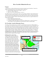
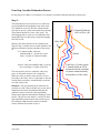
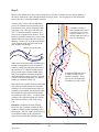
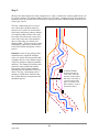
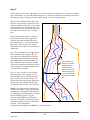
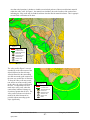
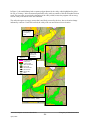
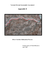
Vermont Stream Geomorphic Assessment
Appendix E
River Corridor Delineation Process
Vermont Agency of Natural Resources
April, 2004
Stream Geomorphic Assessment Handbooks
VT Agency of Natural Resources
- E0 -
April, 2004
River Corridor Delineation Process
Purpose
A stream and river corridor delineation process has been developed as part of the Phase 1 Stream Geomorphic Assessment protocol to create a map overlay area and assess:
Surficial geologic materials and soils (Steps 3.3 and 3.5)
Land cover / land use (Step 4.2)
Berms, roads, and developments (Steps 6.1 and 6.2)
The delineation process recognizes that in some cases, the geologic and land use factors influencing runoff and erosion may extend beyond the toe of the side slope in a narrow valley. The process also recognizes that in wider valleys, human structures on the valley floor do not always alter flood plain characteristics. The process attempts to define a width of land on either side of the river, together called the river
corridor, that will capture:
Factors influencing runoff and erosion;
Factors influencing flood plain function; and
A minimum width of land within the overall valley width that may be occupied by the active
stream channel, as slope and dimension remain in balance with the watershed inputs.
SGAT and the Corridor Delineation Process
The SGAT extension designed for use with GIS is a significant time-saving tool in delineating Phase 1
river corridors. For those stream reaches where you have used GIS to draw valley toe and meander center
lines, SGAT can be used to carry out the four step process described below in a matter of minutes. For
stream reaches where no valley toes and meander center lines were drawn, a default corridor of either 2.5
times the channel width (for a total of 5 channel widths) either side of the centerline or 100 ft (for a total
of 200 feet) either side of the centerline, which ever is greatest, will be drawn by SGAT. A method for
defining meander centerlines is described in Step 2 of the river corridor delineation process. A method
for defining the toes of valley walls is described below. Draw the valley toes as a polygon theme and the
meander centerlines as a line theme. See SGAT User Manual (Steps 7 and 9) for details on theme requirements and uses within the SGAT program.
Defining the Toe of the Valley:
Using soils maps and data in conjunction
with topographic maps determine the location of the toe of the right and left valley
walls. Generally, the toe of a valley wall
can be identified by looking for the break in
slope as the steeper valley wall turns into the
gentle sloped valley floor. Soils data help
with identifying changes in slope and include other soil characteristics that may indicate the need to adjust a valley wall line
one way or the other. Starting at the mouth
of the main stem and tributaries, draw right
and left valley wall toes as continuous lines
to an upstream point where distinguishing
between the valley toes and the stream line
becomes difficult (in confined valleys). Additional valley wall delineation tips and rules
of thumb are offered at the end of this Appendix.
Original valley toes drawn
based only on contour
Corrected valley toe based on soils map, showing
alluvial material beyond change in slope contours.
Stream Geomorphic Assessment Handbooks
VT Agency of Natural Resources
- E1 -
April, 2004
Original Valley Toes
Corrected Valley Toe
Contour Lines
Alluvial Material
Glacial Lake
Glacial Till
Four Step Corridor Delineation Process
For the purpose of a Phase 1 Assessment, river corridors are defined using the following 4 step process:
Step 1.
This delineation process requires the use of the most
recent orthophoto and topographic map of the reach.
The orthophoto is used to draw the corridor and the
topo map is used as a guide to determine the proximity
of the channel and the toe of the valley walls. The
ideal mapping base to work on is an orthophoto with
topographic lines overlain using a computer mapping
tool such as GIS.
Shown as the dotted red lines in the example to the
right, the Step 1 corridor lines are drawn parallel to the
stream at a distance from the centerline of the stream
of:
2.5 x channel widths, where the
bankfull width is > 40 feet (for a total
Step 1 Corridor of 5 channel widths);
5 Channel Widths or
200 ft (if Wbkf ≤40)
Valley Wall
Stream
or
100 feet, where the bankfull width is ≤ 40 feet
(for a total Step 1 Corridor of 200 feet)
The stream can be used as a centerline where it appears, as with small streams, to be a single line.
Where the valley is narrow or the stream is in close
proximity to the valley wall, it is important to draw the
corridor lines so that they extend laterally beyond the
toe of the valley walls.
Total Step 1 Corridor equals
5 channel widths or 200 ft.
measured from the centerline
of stream extended laterally
beyond the toe of the valley.
Rationale: This step identifies those land areas beyond the toe of the valley wall that, may or may not be
important to the stream for planform and slope adjustment, but involve land uses that significantly
change runoff patterns and sediment discharges to the
stream. This process also defines a corridor for those
high amplitude stream meanders that extend beyond
the 4 channel widths from the meander centerline
used to delineate the corridor in Step 2.
Stream Geomorphic Assessment Handbooks
VT Agency of Natural Resources
- E2 -
April, 2004
Step 2.
Shown as the dashed brown lines in the example below, the Step 2 corridor lines are drawn parallel to a
line that is drawn down-valley through meander crossover points. For the purposes of this delineation
process this line is called the meander centerline.
Complete Step 2 of the corridor delineation
process for streams and rivers flowing in valleys measured to be at least 4 channel widths
wide (Step 2-10: valley types NW, BD, and
VB). To draw the meander centerline, first
place crossover points on the channel. These
points are generally located in the center of the
channel where the deepest thread of water (or
thalweg) “crosses over” from the outside bank
of one meander to the opposite bank on the
next meander downstream.
A meander centerline is
drawn through points placed
as meander crossovers and
along the channel every 7-10
channel widths where there is
little or no meandering.
thalweg crossover point
Where there are no discernible meanders (in a
straight or straightened reaches of channel),
continue to add points along the centerline of
the stream at a 7-10 channel widths interval.
Draw corridor lines 4 channel widths either
side of and parallel to a meander centerline
drawn through the crossover points. The total
corridor in an unconfined valley is 8 channel
widths (as calculated in Step 2-8).
8 Channel Widths measured
4 widths on each side of a
meander centerline. These
lines do not extend laterally
beyond the toe of the valley.
Since this stream corridor delineates lands that
may influence runoff patterns and sediment
discharges, as well as planform and slope adjustments in unconfined, depositional streams,
the corridor lines should not extend laterally
beyond the toe of the valley. As shown in the
example to the right, discontinue the corridor
line where the stream is close to the valley
wall.
Rationale: In addition to lands affecting
runoff, the Step 2 corridor includes the belt
width (4-8 channel widths, depending on the
stream type). The belt width is an area critical
to unconfined streams as they adjust their
slope consistent with their sediment regime.
Stream Geomorphic Assessment Handbooks
VT Agency of Natural Resources
- E3 -
April, 2004
Step 3.
Shown as the dotted purple lines in the example below, a Step 3 corridor line is drawn parallel to the valley wall at a distance of 8 channel widths from the toe of the valley. Complete Step 3 of the corridor delineation process for streams and rivers flowing in valleys greater than 4 channel widths wide (Step 2-10:
valley types 2 and 3).
The Step 3 delineation process is necessary only in those situations where the
stream or river reach is in a broad unconfined valley and flowing within a distance
of 4 channel widths from the valley wall.
In reaches where the stream comes close
to the valley wall, draw a line parallel to
the toe of the valley at a distance of 8
channel widths. This line need not extend
longitudinally (upstream or downstream)
beyond lines drawn during Step 2 of this
process.
Rationale: In lieu of any geologic information that may explain the straighter
course of a stream, this Step assumes that
a straight reach in a wide, shallow-sloped
valley may attempt to adjust its planform
and slope. The channel will become more
sinuous to regain equilibrium with the
large supply of fine grained sediments
typically found in unconfined valley segments. The Step 3 delineation process
attempts to include those land areas into
the corridor that may be important to this
adjustment process.
8 Channel Widths
measured from the toe
of the valley, where the
proximity of the channel
and valley wall results in
a corridor (drawn using
Steps 1 & 2) that is less
than 8 channel. (Used in
unconfined valleys)
Stream Geomorphic Assessment Handbooks
VT Agency of Natural Resources
- E4 -
April, 2004
Step 4.
If more than one of the Steps 1 through 3 were required for a given reach, then you will want to complete
Step 4 of this Phase 1 river corridor delineation process. The Step 4 corridor lines encompass all corridor
lines drawn in Steps 1 through 3 to form a single stream or river corridor delineation.
Shown as the solid black lines in the example to the right, the Step 4 corridor lines follow those segments of the Step 1-3 lines that
extend laterally away from the channel. The
only corridor lines to be included outside the
toe of the valley walls are Step 1 corridor
lines.
A
In the example to the right, the corridor for
the stream reach in the valley segment labeled A, the stream corridor follows the
Step 1 corridor lines. This follows because
Step 2 and 3 lines are drawn for streams
flowing in broader valleys at least 4 channel
widths wide.
B
Step 1 and 2 corridor lines were both drawn
for the stream in valley segment B. The
Step 2 lines were followed for the final corridor delineation (solid black line) because
they extend further laterally than the Step 1
lines. Had there been an atypical meander
with a larger amplitude (not shown) the Step
1 lines may have extended beyond the Step
2 lines around the meander.
Step 1, 2, and 3 corridor lines were drawn
for the stream in valley segment C. The
Step 1 corridor line (on the right side) and
Step 3 corridor line (on the left side) were
followed from the final corridor delineation
because they extend further laterally than
any other line drawn in this valley segment.
C
River Corridor delineation is made as
continuous lines
connecting those
portions of corridor
(drawn using Steps
1-3) that extend the
most from the channel.
NOTE: The stream and river corridors delineated for the Phase 1 Stream Geomorphic
Assessment are determined for the purposes
of evaluating the possible impacts of various
factors influencing runoff (i.e., land
use/cover) and floodplain modifications.
They are not intended to empirically show
floodplains, flood prone areas, or flood hazard areas. These delineations
are determined through Phase 2 and Phase 3 field assessments.
Stream Geomorphic Assessment Handbooks
VT Agency of Natural Resources
- E5 -
April, 2004
Valley wall delineation tips and rules of thumb
The valley walls are used, in part, to help define the lateral constraints on the river. In delineating the valley walls it is important to try to establish reasonable estimates of valley toe locations. In certain valleys it
will be necessary for the user to make a reasonable best guess; erring on the side of conservative to define
wider valleys where remote sensing data presents uncertainties. The user may not delineate valley walls
in steeper, more confined valleys where it is harder to distinguish the toes of the valley from the stream
itself.
The 20 foot contour lines on topographic maps may not be detailed enough to give a clear indication of
where the toe of the valley wall may be. To assist in determining the outer limits or toes of the valley
wall, it may be valuable to use the NRCS soils in conjunction with the topographic map. The soils can be
linked in ArcView to the NRCS Top20 table; then displayed on parent material. One of the key parent
materials to look for is alluvium. Using the surficial geology maps to locate bedrock outcrops will also
provide insight into where the geology is restricting the river from moving laterally across a valley.
Once delineated as a shape file in ArcView, print out the valley walls on a topographic map and/or orthophoto, and conduct a field review of valley walls. First, field check those areas where you had questions,
then if time and funds permit review the valley walls in other reaches.
On those reaches where it is not possible to field check the location of valley walls, you may consider
completing a stereoscopic analysis of air photos, which allows the user to view the landscape in 3D. It is
possible to see rises as low as 5 to 10 feet. This process may only be necessary where there are concerns
or issues that dictate the need for more accurate valley walls and a field visit is not possible.
Guidelines
1) If SGAT is to be used; review Step 7 “Requirements for Digitizing Valley Walls” for additional
information on the data requirements for valley walls used in SGAT. (There are a few examples
below that address SGAT issues.)
2) Include all alluvial material, except unreasonable rises, as indicated by topography
3) Use the outer limits of the valley as indicated by the contour lines (where topographic map indicates a wide valley), even if the alluvial material does not fill the valley. Overlaying the topographic contours on the soils map can be a good way of reviewing both topographic features and
soils at the same time.
4) Delineate the toe of the valley wall at changes in elevation greater than 20 feet (indicated by 2 or
more contour lines within a short distance of each other), as this is a good indicator that the river
is not likely to utilize the taller, steeper feature.
5) Include alluvial fans that are within the mainstem valley
Stream Geomorphic Assessment Handbooks
VT Agency of Natural Resources
- E6 -
April, 2004
An often asked questions is whether to include or not include pockets of other (non-alluvium) material
within the valley wall? In Figure 1, the material was included, due to the location of the contour lines
indicating the valley walls may be further back then what the alluvial material indicates. This is appropriate until field verification can be done.
Figure 1
Valley Toes
Contour Lines
Alluvial Material
Dense Till
Glacial Fluvial
Glacial Lake
Glacial Till
Other
The valley wall in Figure 2 was not
extended up to the outer extent of the
alluvial depicted on the soils map.
Alluvial material in the surrounding
area did not extend up the contours in
the same way as this lobe of alluvium.
To keep the valley wall more consistent, and to not create an odd “point”
in the valley, the valley wall bisected
the lobe. A compromise was also
made in the valley wall, where the
contour lines indicated a change in
elevation of greater than 20 feet. The
valley wall was drawn to include as
much of the alluvial material as
possible without extending up the
slope significantly.
Figure 2
Valley Toes
Contour Lines
Alluvial Material
Dense Till
Glacial Fluvial
Glacial Lake
Glacial Till
Other
Stream Geomorphic Assessment Handbooks
VT Agency of Natural Resources
- E7 -
April, 2004
In Figure 3, the small tributary had a separate polygon drawn for the valley walls (highlighted in yellow
for ease of viewing). In the downstream portion the valley walls are outside of the sub-watershed for that
reach. This can cause an error in the calculation of the valley width, because the program will not recognize the valley wall outside of the sub-watershed.
The walls also appear to occupy an area that is not likely accessed by the river; due to elevation change
indicated by contours. Until field verified, the valley wall was moved into a lower elevation.
area not likely
occupied by
river
Figure 3
valley wall
outside subwaterhsed
Sub-Watershed
Valley Toes
Contour Lines
Alluvial Material
Dense Till
Glacial Fluvial
Glacial Lake
Glacial Till
Other
Corrected valley walls
Stream Geomorphic Assessment Handbooks
VT Agency of Natural Resources
- E8 -
April, 2004
Be careful with valley walls outside of the sub-watershed boundaries. In SGAT, if the valley line is outside of
the sub-watershed it will not be counted for the reach. In some cases it is not possible to contain both valley
walls within the sub-watershed for the reach; and in those cases the user will have to manually measure the
valley data for that reach (see Figure 4).
Figure 4 is an example where the
user would not be able to include
both sides of the valley (highlighted
in yellow for ease of viewing) for
one of the mainstem reaches. A
tributary enters the valley and divides the valley into “two” subwatersheds. The user will get an
error in SGAT – Step 7 that the valley information can not be calculated for this reach. The user will be
able to have SGAT skip this reach
and continue with calculating data
for the remaining reaches. Be sure
to note the reach number indicated
in the error message, then come
back and manually measure the valley information.
Reach where only one
valley wall is contained
in the sub-watershed
Valley Toes
Sub-Watershed
Figure 4
Stream Geomorphic Assessment Handbooks
VT Agency of Natural Resources
- E9 -
April, 2004