1
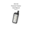
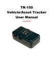
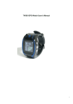
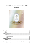
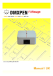
HC512 Portable Tracker
User’s Manual
Table of contents
Chapter I Preface................................................................................................................................................. 3
I. General ...................................................................................................................................................... 3
II. Notices ..................................................................................................................................................... 3
Chapter II About the Device ............................................................................................................................... 3
I. Components .............................................................................................................................................. 3
II. Product Features..................................................................................................................................... 4
III. Product Specifications .......................................................................................................................... 4
IV. LED Display Description ...................................................................................................................... 4
Chapter III Use Preparation............................................................................................................................... 5
I. Accessories ................................................................................................................................................ 5
1.1 Desktop Charger ...................................................................................................................................... 5
1.2 Car Charger (optional) ............................................................................................................................. 5
1.3 Configured Headset(optional) ................................................................................................................. 6
II. Charge the Battery ................................................................................................................................. 6
III. Installation of SIM Card ...................................................................................................................... 6
IV. Meaning of Buttons ............................................................................................................................... 6
Chapter IV Commands Corresponding to and Operation Method of Basic Functions ................................ 7
I. Power on ................................................................................................................................................... 7
II. Function and Operation ......................................................................................................................... 7
1. Location Inquiry .............................................................................................................................. 7
(1) SMS Inquiry ................................................................................................................................... 7
(2) Platform Inquiry ............................................................................................................................ 7
2. Setup of Center Number ................................................................................................................. 8
3. Bi-directional Call Function and SOS Aid Function .................................................................... 8
3. Monitoring Function ....................................................................................................................... 9
4. Automatic Data Upload Interval Setup ......................................................................................... 9
5. Restore Factory Setup ..................................................................................................................... 9
6. Set APN Command .......................................................................................................................... 9
8. Overspeed Alarm ............................................................................................................................. 9
9. Electronic Fence Function ............................................................................................................ 10
Notices: ............................................................................................................................... 错误!未定义书签。
Chapter I Preface
I. General
Welcome to use the GPS tracker. CH512 represents the perfect combination of GSM and GPS
technologies. This model, with compact dimensions, is easy to take and install. With precise dimensions and
compact appearance, expresses the advanced workmanship in the GSM and GPS field. This product can be
used for vehicle rent and logistics business management/the positioning and tracking of the outdoor machinery
and equipment, etc.
As a professional security and positioning company, we will provide you with more and better
products and services. Before use, please spend several minutes reading this user’s manual in order to
understand operation details and obtain better services.
II. Notices
1. Please read carefully this user’s manual and always use correct operation methods to prevent any possible
errors.
2. You need to choose a safe place to install your products. Some dangerous places such as car airbag, the
places easily hurting the driver and passengers and all places not suitable for the storage of this product
shall not install or store this product. Besides, in order to avoid accidents, do not operate this product while
you are driving.
3. This user’s manual is for reference only. If some contents and operation steps are inconsistent with those
for the actual product, the latter will prevail.
Chapter II About the Device
CRT99, as a personal remote positioning device made up of GPS module and GSM/GPRS module, is
compact in dimensions and has high accuracy. On the basis of GPS satellites and under dynamic conditions, it
can provide you with accurate and correct location information. You can use it for safety purpose and other
purposes, such as remote positioning to protect property safety and follow animals, etc.
I. Components
1. Inbuilt GPS Module
2. Internet positioning service
(WWW.HEACENT.COM).
center,
used
to
receive
and
send
positioning
information
II. Product Features
●
●
●
●
●
●
●
●
●
●
●
●
●
●
●
GPS individual or fleet positioning;
Universal in the world;
GSM /GPRS modem supports four frequency bands, i.e. 850/900/1800/1900MHz
High-sensitivity, new workmanship and the most advanced GPS chip;
Can accurately position even if with weak signals;
Can work effectively in limited space such as the remote and narrow places in a city;
Low energy consumption;
Fast signal capturing;
Supports single positioning and continuous tracking;
Supports alarming and remote monitoring;
Supports fast dial button;
Supports the location information inquiry by SMS and Internet
May monitor without disturbing the tracked person and realizes real-time tracking;
Can position the holder by call or mobile phone SMS;
In emergency, press the SOS button to have an accurate positioning.
III. Product Specifications
Technical Specifications
Voltage
3.4V ~ 4.5V
Working temperature
-20°~ 65°
Humidity
5% ~ 95%
Limited working temperature
-30°C~ -40°C and +80°C ~ +85°C
Storage temperature
-45°C ~ +90°C
Start time
Hot start: <1.5s
Accurate positioning
3.0 m 2D-RMS, DGPS: 2.5 m
Speed positioning
0.1m/s,DGPS:0.05m/s
Power consumption
Standby 60mA
Charging port
DC 5V 3A
Warm start: <34s
IV. LED Display Description
Red light (
) indicates the state of being charged.
State
Meaning
Normally on
being charged
Flicker every 3s
Normal start and work
0.2s on and o.2s off (fast flicker)
Start without SIM card inserted.
Green light (
) indicates GSM working state:
State
0.2s on and o.2s off (fast flicker)
0.2s on, 3s off (intermittently flicker)
Meaning
No GSM signal/initiating
GSM/GPRS works normally
Cold start: <35s(Autonomous)
Blue light (
) indicates GPS signal state:
State
Meaning
Normally off
GPS reception off
0.2s on, 3s off (intermittently flicker)
GPS works normally
Combination state
State
Power-off
Red light-power
supply
Off
Power-on, but no SIM card Fast flicker
System works normally Intermittently flicker
Charge
Call in
Normally on
Blue light-GPS
Green light-GSM
Off
Off
Off
Off
Intermittently flicker
Intermittently flicker
Intermittently
flicker Intermittently
flicker
(power-on) Off (power-off) (power-on) Off (power-off)
Red light and blue light flicker at the same time.
Chapter III Use Preparation
I. Accessories
1.1 Desktop Charger
(Figure 3)
1.2 Car Charger (optional)
(Figure 4)
Intermittently flicker
1.3 Configured Headset(optional)
II. Charge the Battery
Before the use of the tracker, please charge the battery at least 4h via the USB charging cable. For the first
charge, in order to bring the performance of the battery into full play, charge it above 12h.
III. Installation of SIM Card
There is one SIM card port on the terminal. According to the direction on the rubber plug, insert the SIM card
into the device and then restore the rubber plug.
·The type of the SIM card is GSM card (the SIM card of China Mobile is recommended).
·Make sure the SIM card has sufficient amount in order to pay the communication cost.
·Prepare one piece of SIM card for mobile phone (the SIM card of China Mobile is recommended), make sure
that card has opened such functions of Caller ID and receiving and sending messages. If necessary, use the
service platform to track the GPRS function to be opened in real time.
IV. Meaning of Buttons
Product Photograph
POWER Button (On/Off Button)
¾ In power-off state, press the Power button for three seconds and then release the button, the device will
enter the power-on state.
¾ In power-on state, press the Power button for three seconds and then release the button, the device will
enter the power-off state.
CALL Button (Dial Button)
¾ Press the Call button for two seconds and then release it, the terminal will automatically dial the preset
phone number.
¾ When there is a call coming in, press the Call button to receive it.
¾ During call conversation, press the Call button to end the call.
SOS Button (Emergency Call Button)
¾ In emergency, press the SOS button for two seconds and then release it, then the device will enter the
emergency alarming state. At the beginning, the terminal will send one piece of alarming message to the
SMS center, then dial the emergency phone numbers having been saved in the terminal in order.
Combined Use of SOS Button and Power Button
¾ During use, the product may have some failures, such as no data upload, failure to power on for many
times or halt. In such case, press the SOS button and the Power button at the same time. Please note that,
in power-off state, press the SOS button and the Power button for several seconds, then press the Power
Button again to power the device on, the device will restore normal. If the device is abnormal in the
power-on state, press the SOS button and the Power button at the same time without pressing the Power
button, then the product will restore normal.
Remarks: It is recommended not to use these buttons generally unless failures occur!
Chapter IV Commands Corresponding to and Operation Method of Basic Functions
I. Power on
In power-off state, press the Power button for three seconds and then release the button, the device will
enter the power-on state.
II. Function and Operation
1. Location Inquiry
(1) SMS Inquiry
Send the *456# command; after successful sending, the monitoring mobile phone will receive the latitude
and the longitude information.. See the flow as follows:
Remarks: In any circumstance, before the center number is set, after this command is sent to the terminal
with any mobile phone, the terminal will return the website information to the inquiring mobile phone. Please
note that, after the center number is set, only the center number can send this command to inquire the terminal
location.
In the same way:
Send *789# to inquire the base station information.
Send *ST,0000000000,S97,130305,00# command to inquire the battery power state.
(2) Platform Inquiry
Step 1: Log onto the platform;
Step 2: Click the terminal of the ward, then the map will display the location of the ward.
2. Setup of Center Number
You can send *ST,0000000000,S2,000000,134xxxxxxxx# command by the SMS control center or GPRS
center. For example:
Set the SMS center number. Before this command is sent, the terminal will respond to the command sent
by any mobile phone; after this command is sent, the terminal will respond only to the command sent by the
SMS center number. After the command is sent successfully, the config OK response message will be returned
to the sending mobile phone.
3. Bi-directional Call Function and SOS Aid Function
By means of GPRS or SMS channel, set the calls that the Call button can dial out and the alarming call by
the SOS button with the command as *ST,1234567890,S95,130305,13333333333#.
1. After the setup is successful, press the Call button, then the terminal will automatically dial this call out;
after the other party receives this call, you can communicate with him/her via headset. At the same time,
pressing the Call button can receive all incoming calls.
Note: The power allowing or not the receiving and dialing calls depends on the operator. The factory setup
is defaulted as able to receive/end calls.
2. After the setup is successful, in emergency, the ward may press the SOS button, then this terminal will
automatically send the alarming information to the SMS center and the GPRS center and automatically dial this
call at the same time.
3. Monitoring Function
The SMS may send *ST,0000000000,R8,000000,13222222222# to the positioning terminal; in such case,
the terminal will automatically call back to such number 13222222222; in such case, this number 13222222222
can hear the surroundings around the ward. Note: Before the SMS center number is set successfully, the
terminal will respond to the command sent by any mobile phone and any mobile phone can monitor this
terminal. Therefore, for purpose of security, before the use of this terminal, make sure that the SMS center
number is set.
SMS format: *ST,0000000000,R8,000000,13222222222#
4. Automatic Data Upload Interval Setup
The control center may send the command *ST,0000000000,S17,000000,30# to the positioning terminal.
In such case, the terminal uploads data to the server center with 30s interval. Changing the number 30 means
changing the upload interval of the terminal.
SMS format: *ST,0000000000,S17,000000,30#
To stop GPRS data upload, send the command *ST,0000000000,S12,000000,02#.
5. Restore Factory Setup
The control center may send the command *ST,0000000000,S25,000000# to the positioning terminal; if
this command is sent successfully, the factory setup will be restored successfully. The SMS center number is
cleared; the upload interval is changed into one minute; the alarming call is cleared and the calls by the Call
button are cancelled, etc.
SMS format: *ST,0000000000,S25,000000#
6. Set APN Command
The control center may send the command *ST,0000000000,S24,130305,0,cmnet,,# # to change the actual
APN in the application environment.
Description
M: Valid mode;
M=0: Virtual inquiry
M=1 or others: Set the name of the access point as APN.
Cmnet is the name of APN, followed by APN user name and APN password.
Remarks: Mainland China does not need to change APN and the defaulted APN is cmnet.
7. Mileage Inquiry Setup
The control center may send the command *ST,0000000000,S32,000000,M# to inquire the operation
mileage of the terminal.
M=0: Clear the mileage counter.
M=1 or others: Inquire mileage.
For example: *ST,000,S32,130305,1#
8. Overspeed Alarm
The monitoring center may send the command *ST,0000000000,S14,130305,100,10,1,3# to the terminal
to realize speed limit.
This command means that, when the terminal speed is more than 100kts or less than 10kts, the function of
speed alarming will occur. To change the overspeed limit, you need only to change the parameters of the
position of 100 and 10 into the ones you want. In this command, if the upper limit or the lower limit is set as 0,
the alarming function of the upper limit or the lower limit will be cancelled.
Remarks: 1kts=1 sea mile/h=1.852km/h
9. Electronic Fence Function
The monitoring center may send the commands
*ST,0000000000,S18,000000,5,1# and
*ST,0000000000,S21,000000,Lx,M,D,Minlatitude,Maxlatitude,G,Minlongitude,Maxlongitude# to send the
electronic fence function.
Lx: x = 1-64 fence number, x=others: forbid all fences
M: Valid conditions;
M = 0: Invalid, forbid this fence with all data following omitted.
M = 1: Activated when the GPS positioning data (A) are valid; forbid vehicles to drive out of the fence; V
means no such fence.
M = 2: Activated whether the GPS data are valid or not (A or V), forbid vehicles to drive out of the fence.
M = 3: Activated when the GPS positioning data (A) are valid; forbid vehicles to drive into the fence; V
means no such fence.
M = 4: Activated whether the GPS data are valid or not (A or V), forbid vehicles to drive into the fence.
M =5 or other numbers: Virtual setup, used to return fence information.
For example: Send one piece of confirmation message *ST,0000000000,S18,000000,5,1#, then send
*ST,2020916012,S21,130305,1,1,N,2245.318,2246.452,E,11233.232,11365.175#; after the confirmation
message is returned, it will indicate that the electronic fence is set successfully.