1
TR-150
Personal Tracker
User Manual
Version 0.1.7
Table of Content
1 Introduction and Features............................................................................................. 3
Introduction ............................................................................................................... 3
Features..................................................................................................................... 3
2 Specifications ................................................................................................................ 4
Hardware ................................................................................................................... 4
3 Start-up......................................................................................................................... 5
Accessories....................................................................................... 錯誤! 尚未定義書籤。
Install SIM card and Battery.......................................................................................... 6
Charging the battery.................................................................................................... 8
4 Hardware Overview ....................................................................................................... 9
Appearance ................................................................................................................ 9
Button description ..................................................................................................... 10
DIP switch ................................................................................................................ 11
5 TR-150 Setup and Call Center Operation ..............................................錯誤! 尚未定義書籤。
Install the USB driver......................................................................... 錯誤! 尚未定義書籤。
Install the Call Center program............................................................ 錯誤! 尚未定義書籤。
Call Center Operation ......................................................................... 錯誤! 尚未定義書籤。
6 Operating the device ................................................................................................... 12
Turn on / Turn off ...................................................................................................... 12
Tracking/Monitoring TR-150 by SMS ............................................................................. 13
SMS Report functions _ Immediate Report .................................................................... 14
SMS Report functions _ Period Report........................................................................... 15
SMS Report functions _ Stop Report ............................................................................. 16
Geofence.................................................................................................................. 17
Voice monitor function ............................................................................................... 20
The format of return SMS from TR-150 ......................................................................... 21
SOS function .................................................................................... 錯誤! 尚未定義書籤。
Configure TR-150 by SMS ........................................................................................... 22
Making a phone call ........................................................................... 錯誤! 尚未定義書籤。
Send out emergency SMS ................................................................... 錯誤! 尚未定義書籤。
11 Appendix ................................................................................................................... 23
FCC Regulations: ....................................................................................................... 23
RF Exposure Information (SAR) ................................................................................... 24
TR-150
page 2
1 Introduction and Features
Introduction
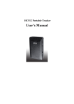
TR-150 is durable and water resistant GPS/GSM tracker. Allow a user to track his
vehicle and assets from anywhere through SMS. TR-150 is designed with high
capacity Li-ion battery for long operation time. There is one SOS button on the
TR-150 for emergency help. It is very easy to install or hide TR-150 in the car to
perform tracking. TR-150 is ideal application for vehicle tracking and
equipment/assets monitoring.
Features
z
SiRF Star III GPS chipset
z
Combination of GPS ,GSM wireless network
z
Durable and water resistant GPS tracker
z
Easy to install or hide in the car to perform tracking. No external wires needed.
z
Ideal application for vehicle tracking and equipment/assets monitoring
z
Optional external antenna for GPS reception
z
Rechargeable 2100mA high capacity Li-ion battery for long operation time
z
External DC power supply
z
Configuration can be done via SMS commands or by application software via USB
interface.SOS (emergency) button.
z
Voice monitor function to monitor the sound/conversation live.
z
Geofence function
TR-150
page 3
2 Specifications
Hardware
GSM module: Siemens GSM 900/1800
GPS Chipset: SiRF Star III
Antenna Type: GPS patch antenna
Dimension: 86.7*48.9*32.5 mm
Battery: 2100mA rechargeable Li-ion battery
LED indicator: For Charging, GPS,GSM and Status.
Interface: Mini USB port for connecting to PC
Casing: Water resistant
GPS external antenna port:
MMCX port
SOS button: SOS button
Mounting bracket with magnet:
TR-150
Optional
page 4
3 Start-up
TR-150
page 5
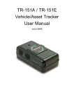
Install SIM card and Battery
z
Use a coin or screwdriver to loosen the screw on back cover.
z
Lift the back cover and remove it as the direction shown.
TR-150
page 6
z
Slide down the SIM card slot as the direction marked “OPEN” on it.
z
Slide in the SIM card with its metal contacts facing down and the cut corner at
the top left.
z
Plug the battery connector into socket. Be aware that the red wire is on the top
side when you plug in the connector.
TR-150
page 7
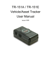
Charging the battery
Before you can use the TR-150, you must complete the following procedures:
1.
Fully charge the battery.
Before your first time using of TR-150, please connect
it with AC power adapter for battery charging under the power-off condition.
(The included battery is specially designed for TR-150. Please do not use other
type of battery; otherwise it will damage the device. If you need to change the
battery for TR-150, please contact you local dealer.)
TR-150
page 8
4 Hardware Overview
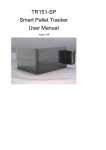
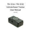
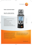
Appearance
TR-150
(1)
Power button
(2)
SOS button
(3)
Indicators
(4)
USB connector
(5)
Microphone
(6)
External antenna connector
page 9
Button description
Power button
1. Power On: Press and hold the power button for 3-4 seconds.
The status LED will flash 2 times
2. Power Off: Press and hold the power button for 3-4
seconds. The status LED will flash 1 time.
SOS button
Presses the SOS Button, the status LED will flash 3 times to
indicate the button is activated. TR-150 will immediately send
out an emergency message along with its GPS report to 3
preset phone numbers.
Indicator
1. GSM LED:
y Voice monitoring: LED steady on.
y When no SIM card inserted, network search in progress,
ongoing user authentication, or network login in
progress: LED is blinking quickly (about once per
second).
y In standby mode: LED is blinking slowly (once per 3
seconds)
2. GPS LED: The LED is steady on when it is fixing the location.
The LED will be blinking when TR-150’s location is fixed.
3. Status LED:
y When battery low: LED steady on.
y When enter setup mode: LED steady on.
y Press power button to turn on: LED will flash 2 times.
y Press power button to turn off: LED will flash 1 times.
y When SOS button is pressed: LED will flash 3 times.
y When encounter error: LED will flash 5 times.
4. Power LED: The LED will be orange when charger is plugged
for charging the battery. When the battery is been fully
charged, the LED goes off.
TR-150
page 10
USB connector
Connecting TR-150 to PC by a Mini USB cable, you can setup all
its features and functions from application software in PC.
You can also plug in USB cable for charging the battery.
Microphone
For voice monitoring use.
External
For you to connect a MMCX external GPS antenna.
antenna
connector
DIP switch
Note: The Factory default of DIP switch is set to OFF.
Switch 1 sets to ON: Enable the Auto-On feature. When external power is connected,
the device will auto-on. When remove external power, the device is off.
Switch 2 sets to ON: All LEDs (except Status LED) go off to perform secret tracking.
Status LED flashes as usual except battery low. (In another word, Status LED is not
on if battery is low.)
Switch 3 sets to ON:
For entering setting mode.
Switch 4: Reserved for future use.
TR-150
page 11
6 Operating the device
Turn on / Turn off
●
Turn on: When the device is off, press the Power button for 3 seconds to turn
on the device. When the device is on, GPS will do cold start to locate its position
for the first time with the green GPS LED on. If location is fixed, the LED will be
blinking. If the location is not fixed in 3 minutes, the GPS function goes sleep
mode for 30 minutes before its next trial. It is suggested that you stay at outer
place or near the window where it can receive the better GPS signal when you
turn on the device.
NOTICE: If it did not finish the successful fix after turned on, it may be difficult
to get fixed in the weak signal area or on the move.
●
Turn off: When the device is on, press the Power button for 3 seconds to turn
it off. When the LEDs go out, it indicates that the device is turned off for sure.
TR-150
page 12
Tracking/Monitoring TR-150 by SMS
SMS Commands for controlling TR-150
Report type
Format
Return
message
0
Immediate report
?0,IMEI,Report_Format,Return_Phone_Number!
$0,IMEI,OK!
1
Period report
?1,IMEI,Report_Interval,Number_of_Reports,
Report_Format,Return_Phone_Number!
?1,IMEI,OK!
2
Stop
?2,IMEI,Return_Phone_Number!
?2,IMEI,OK!
Geofence
?4,IMEI,{[R,longitude,latitude,longitude,latitude],
[C,longitude,latitude,radius(meter)]},In_or_Out,
Report_Interval,Number_of_Reports,Report_Format,
Return_Phone_Number!
?4,IMEI,OK!
4
?6,IMEI,Return_Phone_Number!
6
Voice monitor
Note: If return phone number is empty, TR will call back to Caller ID
Note :
1. Data Report Format:
Report_Format=0 Æ Format0
Report_Format=1 Æ Format1
Please refer to description in this chapter later.
2. Return Phone Number:
Return_Phone_Number
TR will send data report and return message back to this return phone number.
If return phone number is empty, TR will send report back to default SMS return phone number.
If default SMS return phone number is empty neither, TR will send report back to caller ID.
3. Number of Report:
Number_of_Reports=0 Æ continuous report
Number_of_Reports=X Æ X times report
4. Report Interval:
Report_Interval
Set Report Interval in seconds.
TR-150
page 13
SMS Report functions _ Immediate Report
Immediate Report: When TR150 receives the SMS command, it will return a
SMS to confirm the receipt of command. TR150 starts to get position fixed within
the Maximum GPS Fixing Time. If it can not fix the position in the period of time,
it will return the previous location. When the GPS position is fixed, it will again
return the position data.
0
Report type
Format
Return message
Immediate report
?0,IMEI,Report_Format,Return_Phone_Number!
$0,IMEI,OK!
The description of SMS
Format
Description
?0
Start sign and function code
IMEI
IMEI of TR
Report_Format
Ask TR to return message by Format0 or Format1.
(see description below)
Return_Phone_Number
The report message will be sent to the phone number.
!
End sign
Example: Require immediate report in format1 sent to 626-123456
?0,355632000166323,1,626123456!
TR-150
page 14
SMS Report functions _ Period Report
Period Report: When TR150 receives the SMS, it will return a SMS to confirm
the receipt of command. TR150 starts to get position fixed. When the GPS
position is fixed, it will again return the position data, and continue to send back
the data by the Interval Time you set. You can set the number of report in
Number of reports field. If you set “0”, it will not limit the number of report.
1
Report
type
Format
Return message
Period
report
?1,IMEI,Report_Interval,Number_of_Reports,Report_Format,
Return_Phone_Number!
?1,IMEI,OK!
The description of SMS
Format
Description
?1
Start sign and function code
IMEI
IMEI of TR
Report_Interval
Time interval of sending data report. The unit is second.
How many reports will be sent?
Number_of_Reports
Number_of_Reports=0 Æ continuous report
Number_of_Reports=X Æ X times report
Report_Format
Ask TR to return message by Format0 or Format1.
(see description below)
Return_Phone_Number
The report message will be sent to the phone number.
!
End sign
Example 1:
Require continuous 120-sec period report in format1 sent to 626123456
?1,355632000166323,120,0,1,626123456!
Example 2:
Require 10 times, 180-sec period report in format0 sent to 626123456
?1,355632000166323,180,10,0,626123456!
TR-150
page 15
SMS Report functions _ Stop Report
Stop Report: When TR150 receives the SMS, it will return a SMS to confirm the
receipt of command and stop all report modes and back to standby status.
2
Report type
Format
Return message
Stop
?2,IMEI,Return_Phone_Number!
?2,IMEI,OK!
The description of SMS
Format
Description
?2
Start sign and function code
IMEI
IMEI of TR
Return_Phone_Number
The report message will be sent to the phone number.
No report message.
!
End sign
Example:
Send Stop command to disable data report and make GPS off. Return message will be sent to 626123456
?2,355632000166323,626123456!
TR-150
page 16
Geofence
1.
Send SMS command to make TR-150 enter into Geofence mode. The content of
the SMS also includes boundary information (rectangle or circular), in or out to
send alarm, time intervals of alarm report (0 means one time report, X means
the interval is X seconds), return counts, report format and return phone
number.
2.
After the TR-150 enter into this mode, the device will start GPS fixing and the
GPS is always on. Once TR-150 detects the device in or out the boundary, the
TR-150 will send alarm message back to preset number by SMS.
4
Report type
Format
Return message
Geofence
?4,IMEI,{[R,longitude,latitude,longitude,latitude],
[C,longitude,latitude,radius(meter)]},In_or_Out,
Report_Interval,Number_of_Reports,Report_Format,
Return_Phone_Number!
?4,IMEI,OK!
The description of SMS
Format
Description
?4
Start sign and function code
IMEI
IMEI of TR
{[R,longitude,latitude,longitude,
latitude],[C,longitude,latitude,
radius(meter)]}
Boundary information:
R: rectangle Æ Follow by two longitudes, latitudes.
C: circular
Æ Follow by one longitude, latitude and one radius.
In_or_Out
In_or_Out=in
In_or_Out=out
Report_Interval
Time interval of sending data report. The unit is second.
Æ In the boundary to send alarm.
Æ Out the boundary to send alarm.
How many reports will be sent?
Number_of_Reports
Number_of_Reports=0 Æ continuous report
Number_of_Reports=X Æ X times report
Report_Format
Ask TR to return message by Format0 or Format1.
(see description below)
Return_Phone_Number
The alarm message will be sent to the phone number.
!
End sign
TR-150
page 17
Note 1:
User can set up to 10 rectangle or circular boundaries. Each SMS contains one boundary
setting. User can send numerous SMS to complete one set of settings, including numerous
rectangle or circle boundaries. For example, user want to set the boundary includes 2
rectangles and 1 circle. User has to send 3 SMS, two with rectangle information, one with
circle information.
SMS1:
?4,IMEI,R,longitude,latitude,longitude,latitude,In_or_Out,Report_Interval,
Number_of_Reports,Report_Format,Return_Phone_Number!
SMS2:
?4,IMEI,R,longitude,latitude,longitude,latitude,In_or_Out,Report_Interval,
Number_of_Reports,Report_Format,Return_Phone_Number!
SMS3:
?4,IMEI,C,longitude,latitude,radius,In_or_Out,Report_Interval,
Number_of_Reports,Report_Format,Return_Phone_Number!
If user uses numerous SMS in one setting, the IMEI, In_or_Out, Report_Interval,
Number_of_Reports, Report_Format, Return_Phone_Number must be the same between
each SMS. If above parameters are not the same between SMS, TR-150 only follows last
SMS.
Note 2:
In Boundary information
{[R,longitude,latitude,longitude,latitude],[C,longitude,latitude,radius],}
User can set
R: rectangle follows by two longitudes, latitudes.
Or
C: circular follows by one longitude, latitude and one radius.
Example:
Rectangle
R,26.00000,123.00000,27.00000,124.00000
Example:
Circle (radius is 1000 meters)
C,26.00000,123.00000,1000
TR-150
page 18
Note 3:
Example:
Send one SMS to setup Geofence.
Boundary includes one rectangle (two longitudes, latitudes Æ 24.00000,121.00000,
25.00000,122.00000)
When TR is out boundary, sending format1, 10 times , 120 sec interval, alarm message
to 626123456.
?4,355632000166323,R,24.00000,121.00000,25.00000,122.00000,out,120,10,1,616
123456!
Example:
Send three SMS to setup Geofence.
Boundary includes one rectangle (two longitudes, latitudes Æ 24.00000,121.00000,
25.00000,122.00000) and two circles (one longitude/latitude is 26.00000,123.00000,
and radius is 1000 meter ) ( the other longitude/latitude is 27.00000,124.00000, and
radius is 1500 meter)
When TR is out boundary, sending format1, 10 times, 120 sec interval, alarm message
to 626123456.
SMS1:
?4,355632000166323,R,24.00000,121.00000,25.00000,122.00000,out,120,10,1,616
123456!
SMS2:
?4,355632000166323,C,26.00000,123.00000,1000,out,120,10,1,616123456!
SMS3:
?4,355632000166323,C,27.00000,124.00000,1500,out,120,10,1,616123456!
TR-150
page 19
Voice monitor function
1.
2.
6
Send SMS with IMEI and return phone number to TR-150 to enable voice
monitor function.
Then TR-150 call back.
Return
message
Report type
Format
Voice monitor
?6,IMEI,Return_Phone_Number!
The description of SMS
Format
Description
?6
Start sign and function code
IMEI
IMEI of TR
Return_Phone_Number
TR will call back to this phone number.
!
End sign
Note: If return phone number is empty, TR will call back to Caller ID
Example:
User send voice command and make TR call back to 626123456
?6,355632000166323,626123456!
TR-150
page 20
The format of return SMS from TR-150
Data Report Format:
Report_Format=0 Æ Format0
Report_Format=1 Æ Format1
Format0:
Position report
Name
Time Date
GPS position
Fix or not
Example:
Position report
Name
2006/9/15 10:20:39
24.99653,121.48769
GPS fixed
Format1:
?IMEI,Status,GPS_Fix,Date,Time,Longitude,Latitude,Altitude,Speed,
Heading,Number_of_Satellites_in_use,HDOP!
Example:
?353857014816785,2,3,280807,035825,E12129.2616,N2459.7918,97.2,0.13,142.31,04,2
.4!
The description of Format1
Format
?
Value
?
IMEI
The number of IMEI
0
1
3
Status
Note
Command Head
0: Immediate report
1: Period report
3. Time report
1: Fix not available
2: GPS 2D Fix
3: GPS 3D Fix
GPS_Fix
1
2
3
Date
ddmmyy
Time
hhmmss
Longitude
(E or W)dddmm.mmmm
Example:
E12129.2186 Æ E 121°29.2186’
Latitude
(N or S)ddmm.mmmm
Example:
N2459.8915 Æ N 24°59.8915’
Altitude
xxxxx.x
unit: meters
Speed
xxxxx.xx
unit: knots
Heading
ddd
Number_of_Satellites_in_use
xx
HDOP
x.x
!
!
TR-150
(1knots = 1.852km)
Command End
page 21
Configure TR-150 by SMS
1. SMS default return phone number
2. MAX. GPS fixing time
3. Default report mode settings:
a. Default report mode.
b. Return phone number for default report mode.
c. Report interval time
d. Report count
e. Report format
4. SOS numbers
Report type
Format
Return message
SMS Default
Return Number
?7,IMEI,1,Enable_SMSDefaultReturnPhoneNumber,
SMSDefaultReturnPhoneNumber,Return_Phone_Number!
$7,IMEI,1,OK!
Maximum GPS
fixing time
?7,IMEI,2,Maximum_GPS_Fixing_Time,Return_Phone_Num
ber!
?7,IMEI,2,OK!
Default report
mode setting
?7,IMEI,3,Default_Report_Mode,Report_Interval,
Number_of_Reports,Report_Format,Return_Phone_Numbe
r!
?7,IMEI,3,OK!
SOS numbers
?7,IMEI,4,SOS1,SOS2,SOS3,Return_Phone_Number!
?7,IMEI,4,OK!
Enable_SMSDefaultReturnPhoneNumber: Enable SMS Default Return Phone Number, so you can set its
value.
SMSDefaultReturnPhoneNumber: set SMS Default Return Phone Number.
Return_Phone_Number: The report message will be sent to the phone number.
Maximum_GPS_Fixing_Time: If GPS is not fixed within the time, it returns previous location and close GPS.
Default_Report_Mode:
Report_Format: Ask TR to return message by Format0 or Format1.
Report_Interval: Time interval of sending data report. The unit is second.
Number_of_Reports:
Number_of_Reports=0 Æ continuous report
Number_of_Reports=X Æ X times report
TR-150
page 22
11 Appendix
FCC Regulations:
z
This mobile phone complies with part 15 of the FCC Rules. Operation is subject to the following
two conditions: (1) This device may not cause harmful interference, and (2) this device must accept
any interference received, including interference that may cause undesired operation.
z
This mobile phone has been tested and found to comply with the limits for a Class B digital device,
pursuant to Part 15 of the FCC Rules. These limits are designed to provide reasonable protection
against harmful interference in a residential installation. This equipment generates, uses and can
radiated radio frequency energy and, if not installed and used in accordance with the instructions,
may cause harmful interference to radio communications. However, there is no guarantee that
interference will not occur in a particular installation If this equipment does cause harmful
interference to radio or television reception, which can be determined by turning the equipment off
and on, the user is encouraged to try to correct the interference by one or more of the following
measures:
-
Reorient or relocate the receiving antenna.
-
Increase the separation between the equipment and receiver.
-
Connect the equipment into an outlet on a circuit different from that to which the receiver is
connected.
-
Consult the dealer or an experienced radio/TV technician for help.
Changes or modifications not expressly approved by the party responsible for compliance could void the
user‘s authority to operate the equipment.
TR-150
page 23
RF Exposure Information (SAR)
This model phone meets the government’s requirements for exposure to radio waves.
This phone is designed and manufactured not to exceed the emission limits for exposure to radio
frequency (RF) energy set by the Federal Communications Commission of the U.S. Government.
The exposure standard for wireless mobile phones employs a unit of measurement known as the
Specific Absorption Rate, or SAR.
The SAR limit set by the FCC is 1.6W/kg.
*Tests for SAR are
conducted using standard operating positions accepted by the FCC with the phone transmitting at its
highest certified power level in all tested frequency bands.
Although the SAR is determined at the
highest certified power level, the actual SAR level of the phone while operating can be well below the
maximum value.
This is because the phone is designed to operate at multiple power levels so as to use
only the poser required to reach the network.
In general, the closer you are to a wireless base station
antenna, the lower the power output.
The highest SAR value for the model phone as reported to the FCC when tested for use at the ear is
0.758 W/kg for GSM850 / 0.735 W/kg for PCS1900 and when worn on the body, as described in this
user guide, is 0.21 W/kg for GSM850 / 0.223 W/kg for PCS1900
(Body-worn measurements differ
among phone models, depending upon available enhancements and FCC requirements.)
While there may be differences between the SAR levels of various phones and at various positions, they
all meet the government requirement.
The FCC has granted an Equipment Authorization for this model phone with all reported SAR levels
evaluated as in compliance with the FCC RF exposure guidelines. SAR information on this model
phone is on file with the FCC and can be found under the Display Grant section of
http://www.fcc.gov/oet/fccid after searching on FCC ID: RID-TR101.
For body worn operation, this phone has been tested and meets the FCC RF exposure guidelines for use
with an accessory that contains no metal and the positions the handset a minimum of 1.5 cm from the
body.
Use of other enhancements may not ensure compliance with FCC RF exposure guidelines.
If
you do no t use a body-worn accessory and are not holding the phone at the ear, position the handset a
minimum of 1.5 cm from your body when the phone is switched on.
TR-150
page 24